Article

Continuous Gesture Recognition Based on Time Sequence Fusion Using MIMO Radar Sensor and Deep Learning

School of Computer Science and Engineering, Central South University, Changsha 410075, China
*
Author to whom correspondence should be addressed.
Electronics 2020, 9(5), 869; https://doi.org/10.3390/electronics9050869
Submission received: 24 April 2020 / Revised: 19 May 2020 / Accepted: 19 May 2020 / Published: 23 May 2020
(This article belongs to the Section Microwave and Wireless Communications)

Abstract

:
Gesture recognition that is based on high-resolution radar has progressively developed in human-computer interaction field. In a radar recognition-based system, it is challenging to recognize various gesture types because of the lacking of gesture transversal feature. In this paper, we propose an integrated gesture recognition system that is based on frequency modulated continuous wave MIMO radar combined with deep learning network for gesture recognition. First, a pre-processing algorithm, which consists of the windowed fast Fourier transform and the intermediate-frequency signal band-pass-filter (IF-BPF), is applied to obtain improved Range Doppler Map. A range FFT based MUSIC (RFBM) two-dimensional (2D) joint super-resolution estimation algorithm is proposed to obtain a Range Azimuth Map to obtain gesture transversal feature. Range Doppler Map and Range Azimuth Map then respectively form a Range Doppler Map Time Sequence (RDMTS) and a Range Azimuth Map Time Sequence (RAMTS) in gesture recording duration. Finally, a Dual stream three-dimensional (3D) Convolution Neural Network combined with Long Short Term Memory (DS-3DCNN-LSTM) network is designed to extract and fuse features from both RDMTS and RAMTS, and then classify gestures with radial and transversal change. The experimental results show that the proposed system could distinguish 10 types of gestures containing transversal and radial motions with an average accuracy of 97.66%.

1. Introduction

Gesture recognition has been regarded as an effective way of human-computer interaction (HCI) and it has been increasingly applied in many applications [1,2,3]. There are many researches on gesture recognition that is based on computer vision [4,5,6,7]. The Vision-based techniques study the contours, shapes, and textures of gestures. However, vision-based methods require a large amount of computational resource consumption, and they cannot work well in strong light or low light.
In recent years, radar sensor-based gesture recognition has gained a lot of attention. Radar sensors can solve the problem of low recognition accuracy of vision-based system, due to poor lighting conditions, which are ideal for in-car environments with poor lighting conditions. In addition, a radar system is able to protect the user’s privacy better than the vision-based system. Therefore, radar-based gesture recognition system has very broad application prospect and far-reaching application value in practical applications [8,9,10,11,12,13,14,15,16,17]. There are some hand gesture recognition methods that are based on Doppler radar [9,10]. However, Doppler radar can only get the Doppler information, also called velocity information, but it cannot get the range information of target. Therefore, there are some limitations of the types of gestures with Doppler radar. Frequency modulated continuous wave (FMCW) radar is a kind of radar that is capable of both range and velocity measurement, compensating for the range parameters lack of Doppler radar. In [11,12], the authors presented dynamic gesture recognition systems that are based on 77 GHz FMCW radars by while using micro Doppler features and for driving assistance. However, only the Doppler estimation was employed for recognition, and the range information was ignored. In [13], Latern, a FMCW radar-based system with range information employed, was presented for continuous gesture recognition. The difficulty of [13] lies in how to distinguish hand movement trajectory at the same range. In [14,15,16,17,18], two-dimensional-FFT (2D-FFT) was used to process signals to generate the Range–Doppler Map (RDM) containing radial range and velocity information of hand gesture. Google presented Soli, a robust, high-resolution, low-power sensing technology that is based on millimeter-wave for hand gesture recognition [14]. Wang Y et al. presented TS-I3D network to extract range and velocity information of RDM for gesture recognition [15]. In these literatures, only RDM was generated for classification and lack of angular parameter, limiting gesture types for gesture recognition. These methods gradually cannot adapt to real complex gesture recognition, including radial and transversal motions.
Gesture feature extraction and classification are also very important of hand gesture recognition. Convolutional Neural Network (CNN) was used to extract features and classification of image for gestures recognition [1,18,19,20]. Three-Dimension Convolution Neural Network (3DCNN), which was developed to extract motion features encoded in a few consecutive frames, was widely used in various types of continuous behavior recognition, including hand gesture recognition [21,22,23,24]. 3DCNN can learn temporal information of a few consecutive gesture pictures, but is too shallow to learn long term information. When compared with 3DCNN, Long Short Term Memory (LSTM) network is more suitable to learn long-term temporal information. LSTM, which is a special form of RNN network [25], is employed to learn long term information [26,27]. LSTM was employed in [16] to learn the temporal characteristics of the RDM sequences of hand gesture. However, the authors in [16] directly extract the range and Doppler features respectively rather than using deep learning network structure, ignored the joint information between range and Doppler, which makes the feature extraction incomplete.
Aiming at the problem of insufficient parameters of hand gestures recognition, we proposed a new range FFT based MUSIC (RFBM) 2D joint super-resolution estimation algorithm to generate a Range Azimuth Map (RAM) for Range and Azimuth joint Estimation, making up for the lack of lateral parameters. The RAM and RDM of each frame can form Range Doppler Map Time Sequence (RAMTS) and Range Doppler Map Time Sequence (RDMTS). RAMTS and RDMTS were combined for gesture recognition, which expands the variety of gestures for recognition. We designed a dual stream 3DCNN-LSTM (DS-3DCNN-LSTM) network to extract and fuse RDMTS and RAMTS features and classify gestures to more effectively extract gesture spatiotemporal features.
The contributions of this paper are summarized, as follows:
(1)
The development of a new system for hand-gesture recognition based on FMCW MIMO radar and deep learning.
(2)
Designing a pre-processing algorithm based on windowed Range–Doppler-FFT and intermediate-frequency signal band-pass-filter (IF-BPF) to alleviate spectrum leakage and suppress clutters in RDM.
(3)
Proposing a RFBM 2D joint super-resolution estimation algorithm to generate RAM for joint estimation of range and azimuth.
(4)
Designing a DS-3DCNN-LSTM network to extract and fuse RDMTS and RAMTS to obtain high recognition accuracy of complex gestures.
The proposed hand gesture system mainly consists of hand gesture data collection part, signal processing part, and gesture recognition part. Figure 1 shows the simplified block diagram of gesture recognition system. In gesture data collection part, the IF signal data are collected for signal processing. In signal processing part, window functions and IF-BPF are employed on IF signal to alleviate the spectrum leakage and filter background clutter. Subsequently, Range Doppler FFT is employed to obtain RDMTS. Meanwhile, the RFBM 2D joint super-resolution estimation algorithm is used to obtain RDMTS. In the recognition part, RDMTS and RAMTS are input to DS-3DCNN-LSTM and the classification results are given.

2. FMCW MIMO Radar

The employed FMCW radar is millimeter wave radar sensor with three transmitters and four receivers. We use two transmitters and four receivers to generate a virtual array of eight receiving antennas. The signals are generated by synthesizer and transmitted by two transmitters. The signal is received by four receivers after being reflected by target. The received signal is mixed with transmit signal to obtain IF signal. We used one transmitter and two receivers to show the work process of FMCW MIMO radar sensor. Figure 2 shows the simplified block diagram.
The employed radar sensor radiates sawtooth modulated waveform. The transmitted saw tooth FMCW signal consists of several frames, and each frame contains many chirps; a chirp is a sinusoid or a sin wave whose frequency increases linearly with time. The received IF signal can be expressed as
S I F ( t ) = A I F e j 2 π ( K t τ 1 2 K τ 2 ) j Δ ϕ
where K = B T is the slope of chirp, B is the bandwidth of the transmitted signal, and T is the chirp duration, A I F is amplitude of IF signal, and τ and Δ ϕ denote time delay and phase shift caused by hand, respectively.
According to Equation (1), the target range R can be calculated by
R = | f I F | × c 2 K
where c is the speed of light and f I F is the principal component of IF signal. For a frame periodicity, Δ R = v T , so the radial velocity v of object can be calculated by
v = λ Δ ϕ 4 π T = λ f d 2 T
where f d is the Doppler frequency. The range information could be obtained by performing Range-FFT along the fast time. The radial velocity information can be obtained by applying Doppler-FFT on the IF signal along the slow time.
A pair of transceiver antennas can realize the Range Doppler estimation. However, at least two receiving antennas are needed for azimuth estimation. MIMO radar with multiple TX and multiple RX antennas provides a cost-effective way to improve the radar angle resolution [28]. We used a 2T4R MIMO radar to generate a virtual array of eight RX antennas. Transmit antenna TX1 and TX3 are horizontally spaced at d = 4 d r and four receives are horizontally spaced with an interval of d r , as shown in Figure 3a. The phase difference between adjacent antennas ω is calculated by
ω = 2 π d r s i n θ λ
where θ is the angle of arrival. The unambiguous measurement of angle requires | ω | π , so d r = λ / 2 is for the largest field of view [28].
A transmission from TX1 results in a phase of [0ω 2ω 3ω] at the four RX antennas. Any signal emanating from TX3 traverses an additional path of length 4 d r sin θ when compared to TX1 because the second TX antenna (TX3) is placed a distance of 4 d r from TX1. Correspondingly, the signal at each RX antenna sees an additional phase-shift of 4ω (with regard to transmission from TX1). The phase of the signal at the four RX antennas, due to a transmission from TX3, is [4ω 5ω 6ω 7ω]. Concatenating the phase sequences at the four RX antennas obtains the sequence [0ω 2ω 3ω 4ω 5ω 6ω 7ω], as shown in Figure 3b. Thus the 2TX–4RX antenna configuration of Figure 3a synthesizes a virtual array of 8 RX antennas, as shown in Figure 3b. In this work, time division multiplexing (TDM) [29] is employed to separate different transmit signals.
According to Equation (4), θ can be calculated by
θ = sin 1 ( λ ω 2 π d r )
A virtual array of eight receive antennas is constructed and the received raw data are rearranged to conform to the data processing model of virtual array. The angle information can be obtained by using DOA estimation methods based on Equation (5). There are many DOA estimation methods [30,31,32,33,34,35,36,37], such as MUSIC [30,31,32], ESPRIT [33], and Capon [34,35]. In this paper, we design a RFBM 2D joint super-resolution algorithm to obtain information of range and azimuth. We need rearrange the received data to make it suitable for signal processing. The collected data are reshaped to a cube matrix:
s ( n , p , l ) = exp ( j 2 π [ ( 2 K R c + f d ) n 1 N T + 2 f c R c + f d p T + ( l 1 ) d r s i n θ λ ]
where n = 1 , 2 , , N ,   p = 1 , 2 , , P F , l = 1 , 2 , , L , and N are the samples within the time duration T , P is the number of consecutive chirps in one frame and F is the total frames, f c is carry frequency, and L is the number of virtual receiving antennas. In Equation (6), the three dimensions of matrix s contain information of range R , Doppler f d and azimuth θ .

3. Signal Processing

In this section, we describe the signal processing methods of FMCW MIMO radar, including the pre-processing method of improved RDM generation to obtain gesture radial information and a RFBM algorithm for RAM generation to obtain gesture lateral information.

3.1. Generate RDM

This section introduces the generation process of traditional RDM and a pre-processing method, including window functions and an IF band-pass-filter for improved RDM.

3.1.1. Generate Traditional RDM

Since the matrix s contains Range–Doppler information in all frames, the Range–Doppler-FFT is performed in each frame to reveal the change of range and velocity in time. Figure 4 shows the calculation process of Range–Doppler FFT. A range-FFT performed on each column resolves objects in range, and a Doppler-FFT along each row resolves each column (range-bin) in velocity. The Doppler-FFT is accumulated in the results of fast-time axis, so that the traditional RDM can be obtained. The RDM reflects range and velocity information of object. Figure 5a shows the obtained traditional RDM of real data after Range Doppler FFT.

3.1.2. Window Functions for Spectrum Leakage Suppression

There will be spectrum leakage when conducting FFT operation. Spectrum leakage will reduce the spectral resolution and make it hard to detect real object. We consider applying a window function before FFT operation to reduce spectrum leakage in order to solve this problem. The Hanning window [38] is able to alleviate spectrum leakage with a good frequency resolution. Therefore, Hanning is applied to window the signals of Range dimension and Doppler dimension respectively. The Hanning window calculation formula for time domain signal of Range and Doppler dimensions of the fifth frame signal is as follows
{ s r w ( N , P , f ) = s ( N , P , f ) × H a n n i n g ( N ) s d w ( N , P , f ) = s r w ( N , P , f ) × H a n n i n g ( P )
where s r w ( N , P , f ) is the result of Hanning window for s in range dimension, and s d w ( N , P , f ) is the result of Hanning window for s in Doppler dimension. Figure 5b shows the obtained RDM after windowing and Range Doppler FFT.

3.1.3. Designed IF Band-Pass-Filter (IF-BPF) for Clutter Suppression

Besides hand gesture echoes, there will be background clutters in real experimental scene. In addition, there will be interference between the antennas. These situations may cause clutters in RDM. As can be seen in Figure 5a,b, there are peaks at almost all range bins when the velocity is 0, which are caused by the interference of antennas. It can be observed that that there are peaks at range from 1.5 m to 2 m. Based on the analysis of the experimental environment, the peaks are the echo spectrum of ceiling. The motion range of gesture is approximately 0.1–0.7 m, so the targets beyond this range can be considered to be interference or clutters.
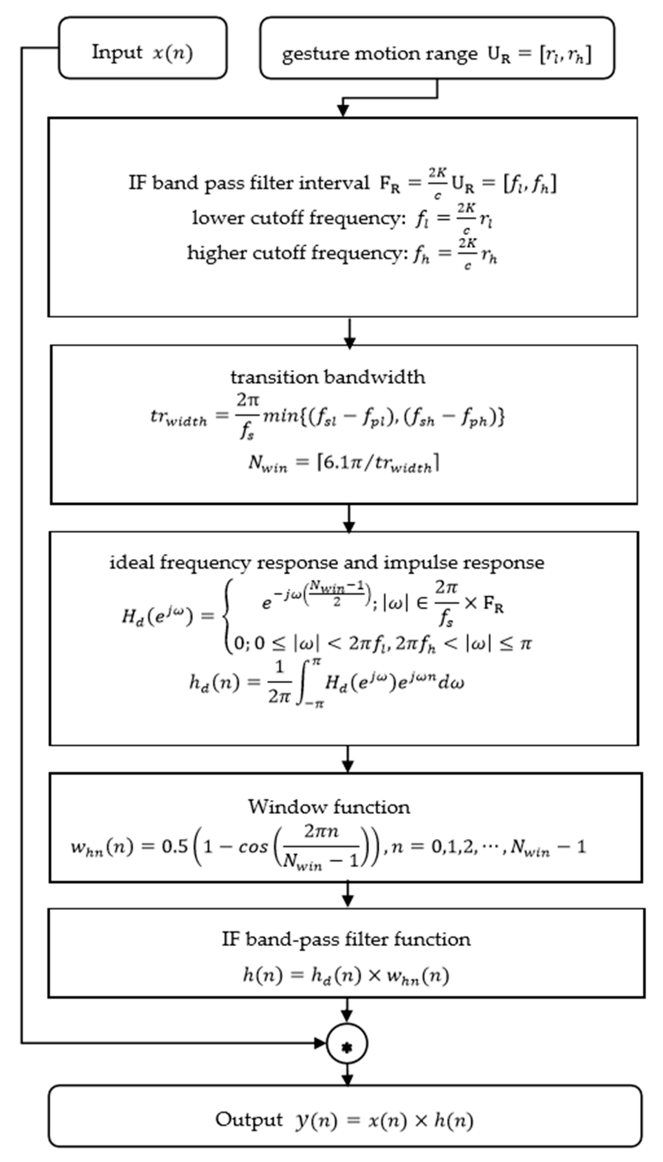
The Constant False-Alarm Rate (CFAR) detector can be employed to reduce background clutter and detect target [39]. However, for strong background clutter situation, it is easy to detect false target by CFAR, and there is incomplete feature extraction of CFAR. The motion range of gesture is approximately 0.1–0.7 m, and there are still strong peaks beyond this interval in spectrum. According to Equation (2), we know that the IF signal is proportional to range, we consider filtering clutters by filtering the low and high frequency in IF signal. Therefore, we designed an IF-BPF to filter background clutters in RDM. Figure 6 shows the block diagram of this designed IF-BPF.
Where x ( n ) = s r w ( N , p , f ) , r l , and r h are the minimum range and maximum range of gesture, respectively. For filter parameter, f l and f h are the lower passband cutoff frequency and the higher passband cutoff frequency, respectively, where f l [ f p l , f s l ] , f h [ f p h , f s h ] , and f p l , f s l , f p h , f s h are the lower passband cutoff frequency, the lower stopband cutoff frequency, the higher passband cutoff frequency, and the higher stopband cutoff frequency, respectively. Additionally, f s = N / T is the sampling frequency ( N is the samples within the time duration T ), and · denotes the ceiling function, rounding toward positive infinity. For band-pass filter function, h d ( n ) are the unit sampling response sequence, h ( n ) is the system function of band-pass filter. The output y ( n ) no longer contains the frequency components of | f | > f l or | f | < f h , but only reserves the component of | f | F R .
According to IF-BPF algorithm, most of the frequency components of background are filtered out, and the frequency components of the responding gestures are enhanced. Figure 5c shows the RDMs of IF-BPF. We can see in Figure 5 that spectrum leakage is well alleviated by windowing and the background clutter is suppressed by IF-BPF. The gesture spectrum is enhanced, which makes it obvious for identification.

3.2. Generate RAM

This section describes a Range FFT based MUSIC 2D joint super-resolution estimation Algorithm (RFBM). This algorithm can realize range and azimuth joint estimation, so as to obtain the lateral information of gesture.
The generation of RAM requires joint estimation of range and azimuth. The range azimuth dimension data of cube matrix s in Equation (6) are selected for estimation. We adopt the first chirp of each frame in order to generate a RAM for each frame signal. Algorithm 1 introduces the proposed RFBM 2D joint super-resolution estimation algorithm.
Algorithm 1 RFBM joint super-resolution estimation algorithm
Input: S 1 = s ( N , p 1 , L ) , p 1 , = P ( f 1 ) + 1 , is the first chirp of the f t h frame signal of matrix s .
Initialization: n = 1 is the number of iterations.
(1) Matrix rearrangement. Rearrange 3-D matrix S 1 to a 2-D matrix S L × N . Matrix S L × N represents N sampling points in one signal chirp of the L virtual antennas chirp.
(2) FFT. Conduct Range FFT along the fast time dimension, and get matrix S L × N .
S L × N = FFT ( S L × N )
(3) Select the n t h column of matrix S L × N .
A = S L × N ( L , n )
(4) Calculate covariance matrix.
R x x = 1 L A A H
(5) Obtain the noise subspace E N . Perform the singular value decomposition of the covariance matrix R x x and get E N .
R x x = E S Σ s E S H + E N Σ N E N H
Where E S and E N are signal subspace and noise subspace, respectively.
(6) Determine steering vectors and angle search space.
VecA = [ θ d , θ u ]
Where θ d and θ u indicate the upper and lower bounds of angular search space VecA , respectively.
Steering vectors is shown as
a ( θ i ) = [ 1 , e j 2 π d r s i n θ i / λ , , e j 2 π ( L 1 ) d r s i n θ i / λ ] , θ i VecA
(7) Calculate the MUSIC spatial spectrum.
P M U S I C ( n , θ ) = 1 a H ( θ ) E N E N H a ( θ )   , θ VecA
(8) Iteration.
n n + 1
Repeat from (3) to (7) until n > N
Output: P M U S I C ( n , θ )
The obtained spectrum P M U S I C ( n , θ ) form a 2D range-azimuth space, called Range Azimuth Map (RAM).
The RAM reflects the range and azimuth information of the real target. Figure 7 shows the RAMs of target at different angular positions. The peaks in Figure 7 are the spectrum of object, and the corresponding values of abscissa and vertical axis are the estimated azimuth and range of target. Figure 7a shows the RAM of target at about −20°. Figure 7b shows that the estimated azimuth is approximately 0°. Figure 7c shows the RAM of target at about 20°. We can see that RAM can effectively reflect the range and azimuth information of real target.
Each frame signal can generate a RDM and a RAM with the above signal processing method. The RDM and RAM of each frame signal then form a RDMTS and a RAMTS in gesture recording duration, which represent the continuous radial and transverse motion information of gesture.

4. Dual Stream 3DCNN-LSTM Networks

3DCNN can extract temporal information of a few consecutive pictures, but is not enough to learn long term information from a long picture sequence. When compared with 3DCNN, Long Short Term Memory (LSTM) network is more suitable for learning long-term temporal information. In this paper, there are 30 frames in a gesture duration and 30 consecutive RDMs and RAMs respectively. 3DCNNs are employed to extract short-term spatiotemporal features first, and then LSTMs are employed to learn long-term spatiotemporal features of RDMST and RAMTS. Deeper spatiotemporal information can be learned in this way.
Inspired by [15], we proposed a dual stream 3DCNN-LSTM networks for feature extraction. When compared to [15], we have two different points. Firstly, only RDM was obtained in [15], in this paper, we can not only obtain the RDMTS, but also get the RAMTS by proposing the RFBM algorithm. Therefore, we proposed a dual-stream concept. Dual-stream refers to the use of two-way network to extract the features of RDMTS and RAMTS separately and then merge them.
Secondly, in [15], an I3D network and LSTMs were employed to extract RDM features. In this paper, since both RDMTS and RAMTS contain spatiotemporal features of gestures, 3DCNNs are employed to extract short-term spatiotemporal features first, and then LSTMs are employed in order to learn long-term spatiotemporal features of RDMST and RAMTS. Finally, the features are fused.
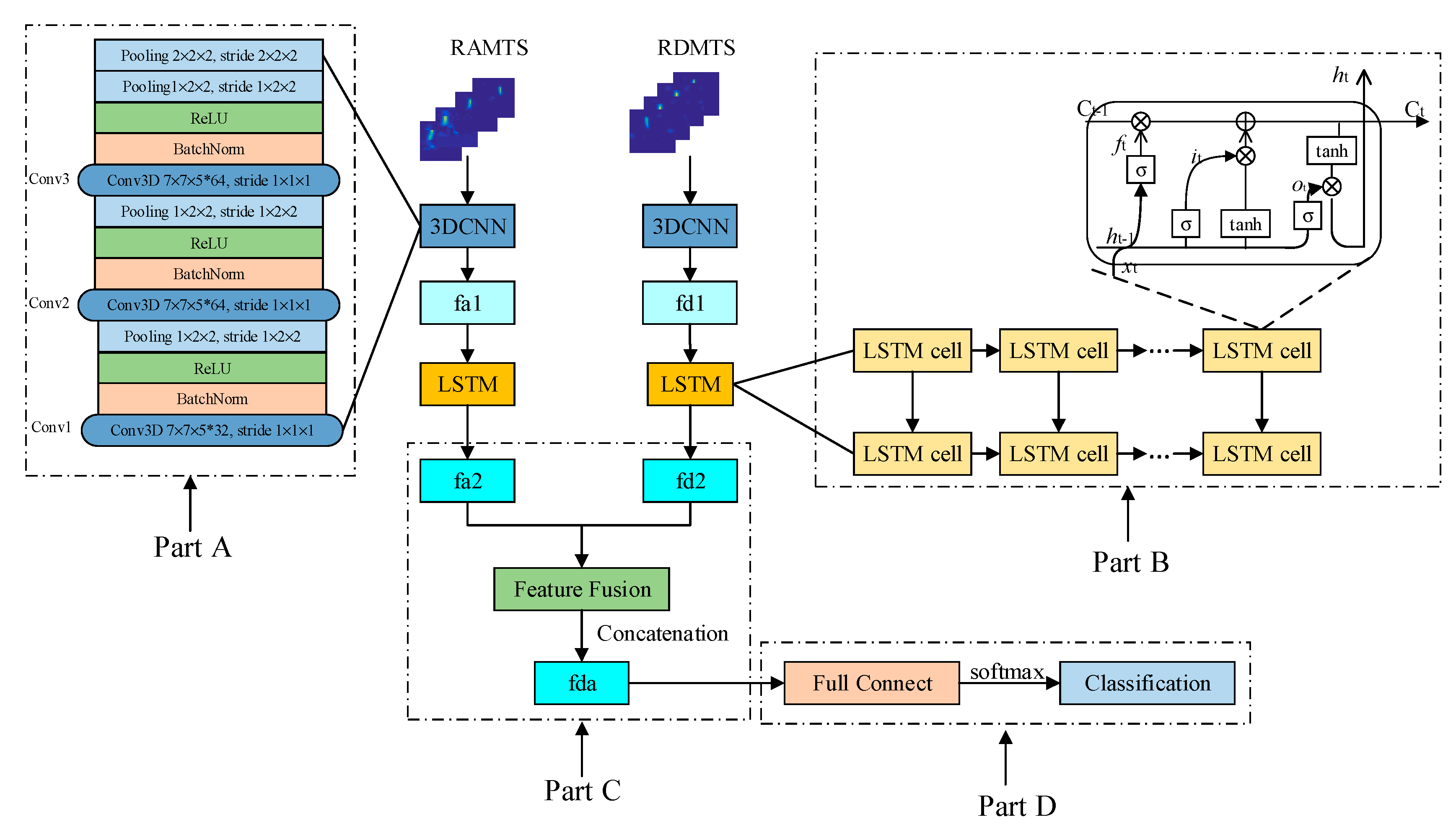
The detailed feature extraction process of proposed network contains two parts: First, two 3DCNNs are employed to learn short-term spatiotemporal features of RDMTS and RAMTS. The learned features of RDMTS and RAMTS are called f d 1 and f a 1 . Second, two LSTMs are employed to extract long-term spatiotemporal features accumulated in f d 1 and f a 1 . The extracted features of f d 1 and f a 1 by LSTMs are vectors called f d 2 and f a 2 . The f d 2 and f a 2 with size of 1600 contain radial and transversal information of gesture. After LSTMs feature extraction, the extracted features f d 2 and f a 2 are fused in order to form a fusion feature vector f d a with a 3200 size. The fusion feature f d a contains distance, velocity, and azimuth information for continuous gestures. The fusion feature f d a is input to the two-layer fully connected (FC) layers to reduce the dimensionality of features and output 10 categories. A softmax function is employed in the final FC layer for classification. Figure 8 shows an overview of proposed deep learning architecture.

4.1. 3DCNN

In this paper, 3DCNNs are employed. Since two 3DCNNs are employed to learn short-term spatiotemporal features of RDMTS and RAMTS, the employed 3DCNNs does not need to be particularly deep, different from [15], only three Conv3D layers are therefore constructed. The kernel size of each Conv3D layer is 7 × 7 × 5 with stride 1 × 1 × 1. Batch normalization [40] is utilized to accelerate the training process. The batch norm is followed by an activate function, restricted linear units (relu). The number of filters of 3DCNN are set to be 32, 64, 64, respectively. The last Conv3D layers is connected to the two-stacked pooling layers to reduce the output size of 3DCNN component. Figure 7: Part A shows the 3DCNN component of this paper.

4.2. LSTM

The output of 3DCNN reshapes the formatting of LSTM. The LSTM component of proposed architecture is displayed in Part B of Figure 7. The LSTM network is composed of LSTM cells, which contains memory cell C t , forget gate f t , input gate i t , and output gates o t . The cell stores information of previous steps and determine output of current step. Subsequently, the connection of each step is maintained. The LSTM cell can be formulated as
{ f t = σ ( W x i × X t + W h f × H t 1 + b f ) i t = σ ( W x i × X t + W h i × H t 1 + b i ) C ˜ t = t a n h ( W x C × X t + W h c × H t 1 + b C ) C ˜ t = t a n h h ( W x C × X t + W h c × H t 1 + b C o t = σ ( W x o × X t + W h o × H t 1 + b o ) H t = o t t a n h ( C t )
where denote the Hadamard product, σ = 1 1 + e x is the sigmoid function, W x ~ ,   W h ~ are 2D convolution kernels, and b i , b f , b o are the offset.
Deep LSTM structure with two LSTM layers stacked, as illustrated in Figure 7, are constructed to learn the long-term spatiotemporal features of f d 1 and f a 1 in order to better learn long-term features. Each LSTM layer is composed of 1600 cells, so the sizes of learned features are 1600. For f d 1 and f a 1 , the two LSTM structures are identical. The two learned deep spatiotemporal features by LSTMs, f d 2 and f d 2 , are concatenated to a fusion feature f d a of 3200 × 1. Two-layer FC layers are constructed in order to reduce dimensionality and map fusion features to 10 categories. A softmax function is employed in the final FC layer to output classification results.

5. Experiments and Result Analysis

The employed devices for hand gesture recognition are IWR1443millimeter wave radar sensor [41] and DCA1000 [42], a data capture adapter, made by Texas Instruments. Figure 9 shows the radar signal data acquisition module. Table 1 shows the experiments setup and parameters configuration of FMCW MIMO radar. Two stream 3DCNN and LSTM built under tensorflow are used for training and testing. The number of epochs, batch size, and learning rate are set to 20, 16, and 5 × 10 4 , respectively. The host for signal processing and deep learning training and testing is configured with the Inter i7-9700K processor and GIGABYTE-RTX2080 super graphics card.

5.1. Experimental Setup and Data Collection

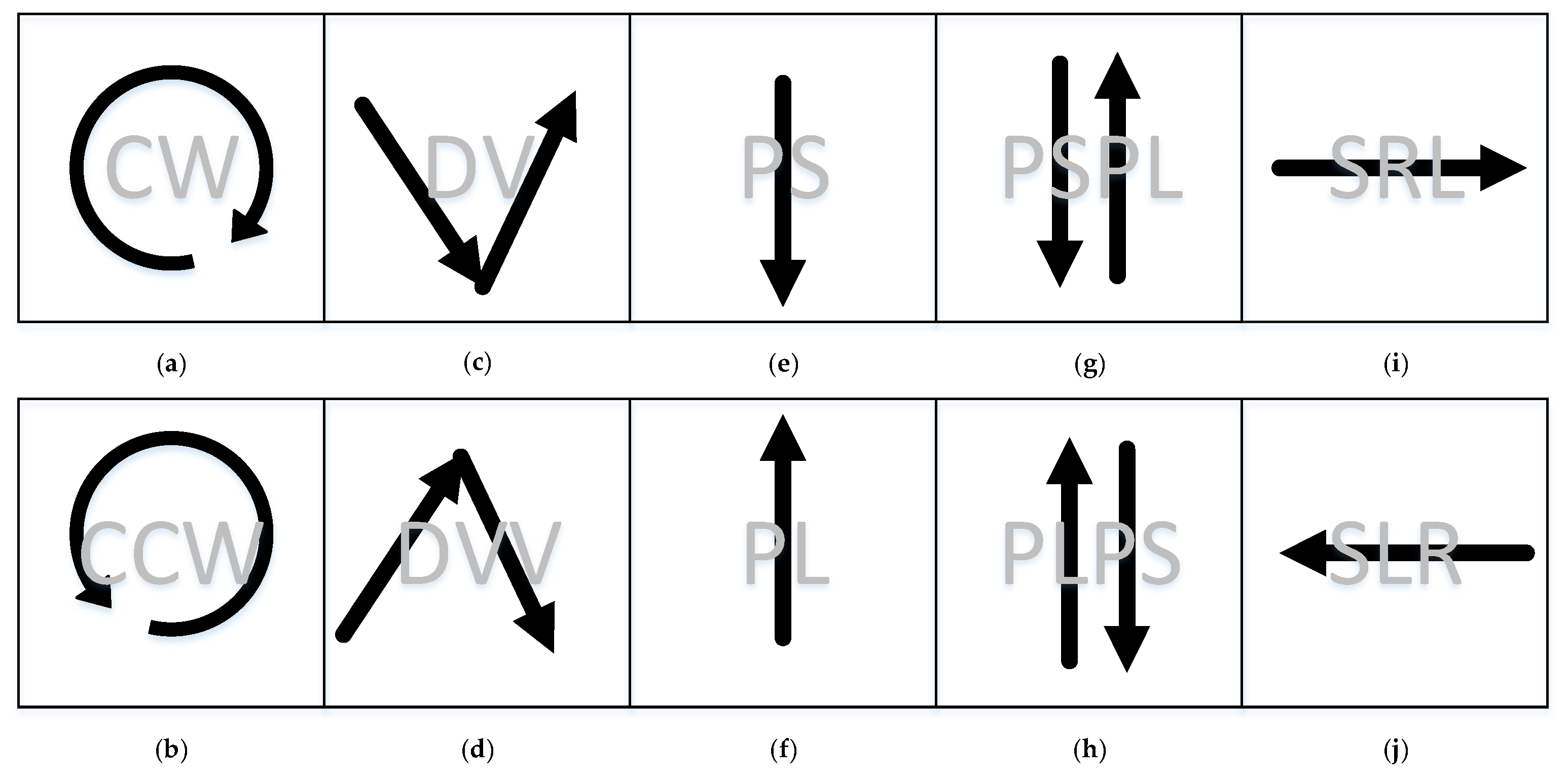
We designed 10 gestures in pairs that are easily confused in a single dimension, radial, or transversal dimension. The 10 types of hand gestures are (1) Clockwise(CW), (2) Counter Clockwise(CCW), (3) Drawing V(DV), (4) Drawing verse V(DVV), (5) Push(PS), (6) Pull(PL), (7) Push and Pull(PSPL), (8) Pull and Push(PLPS), (9) Sliding Right to Left(SRL), and (10) Sliding Left to Right(SLR), as shown in Figure 10. The above gestures can provide potential applications in many HCI applications. For instance, CW and CCW are used to turn up or turn down the volume, and SRL and SLR are able to switch channels.
The gesture data of different experimenters are collected in order to generate data set for good robustness. Five volunteers, three men and two women, were recruited to participate in the experiment. Every participant performed every gesture for 20 times, and each gesture was performed 100 times, so a total of 1000 hand gesture data sets were obtained. The data sets are divided into two parts: training set and testing set. The ratio of training set and testing set are set to be 8:2. The data sets are divided into two parts: training set and testing set. There are 800 hand gesture data sets for training and 200 hand gesture data sets for testing. Each gesture contains two sequences (RDMTS and RAMTS), so there are 1600 training sequences and 400 testing sequences. Radar sensor and data capture adapter are fixed to a table towards the ceiling in order to reduce the interference of the human body on the spectrum.

5.2. Signal Processing Results and Analysis

5.2.1. RDMTS with Windowing and IF-BPF

In this experiment, there are total 30 frames for a gesture duration. Each frame of signal will obtain a RDM; there will be 30 frames RDM to form a RDMTS. We employed 30 frames RDM to represent a gesture. Several RDMs without windowing and IF-BPF of a push gesture are obtained as an example, as shown in Figure 11. In Figure 12, there are RDMs after windowing and IF-BPF of the same push gesture. When comparing Figure 11 and Figure 12, we can find that after windowing and IF-BPF, the target in RDM is more obvious. The highlight in RDM is the gesture echo spectrum. We can learn from frame 1, frame 7, frame 12, frame 7, frame 12, frame 22, and frame 28 that the range is decreasing, which means the hand is approaching the radar. Additionally, the velocity changes from zero to negative and then becomes zeros, which is also consistent with the trend of velocity of real hand gesture.

5.2.2. RDMTS with RFBM Algorithm

According to Algorithm 1, each frame of signal will obtain a RAM, there will be 30 frames RAM to form a RAMTS. We employed 30 frames RAM to represent a gesture. There are several RAMs of different frames of a sliding left to right gesture as example, as shown in Figure 13. The RAMTS reflects hand location change relative to radar during the movement of the hand. We can see from RAMTS that the azimuth changes from about −40° to 0° and then to about 20°, reflecting the location change of the hand during the hand motion.

5.3. Classification Accuracy

Table 2 presents the confusion matrix of 10 types of hand gestures to analyze the misclassification of 10 gestures. It can be seen that the proposed system is able to recognize 10 types hand gestures with high accuracy, ranging from 85.7% to 100%. There are seven types of gestures that achieved 100% gesture recognition accuracy, and three other gestures achieved a recognition rate of 94.4%, 85.7%, and 88.9%, corresponding to three complex gestures, CW, DV, and PLPS, respectively. The recognition accuracy of the entire data set has reached 97.66%.

5.4. Impact of Signal Processing Method on Accuracy

5.4.1. Impact of RFBM Algorithm

A very important contribution of this paper is the addition of RAMTS to represent the lateral change of gestures, which is rarely involved in other papers. Several different training strategies are utilized to evaluate the combination of both RDMTS and RAMTS in order to verify the effectiveness of lateral information on the accuracy of gesture recognition.
Strategy 1: training 3DCNN-LSTM with only RDMTS. Since only RDMTS is considered in experiments, only one 3DCNN-LSTM but not DS-3DCNN-LSTM is need. There is no step of feature fusion, and the features of RDMTS are directly input to the fully connected layer for classification.
Strategy 2: training 3DCNN-LSTM with only RAMTS. As with the RAMTS training process, there is no feature fusion step. The features of RAMTS are directly input to the fully connected layer for classification.
Strategy 3: training DS-3DCNN-LSTM with RDMTS and RAMTS. RAMTS and RDMTS are input to the network at the same time, and the features after DS-3DCNN-LSTM are concatenated to the fully connected layer for classification.
Table 3 shows the recognition accuracy comparison of different training strategies. It is observed that the accuracies of Strategy 1 and Strategy 2 are lower than Strategy 3, which verifies the effectiveness of the combination of RDMTS and RAMTS.

5.4.2. Impact of Window Function and IF-BPF

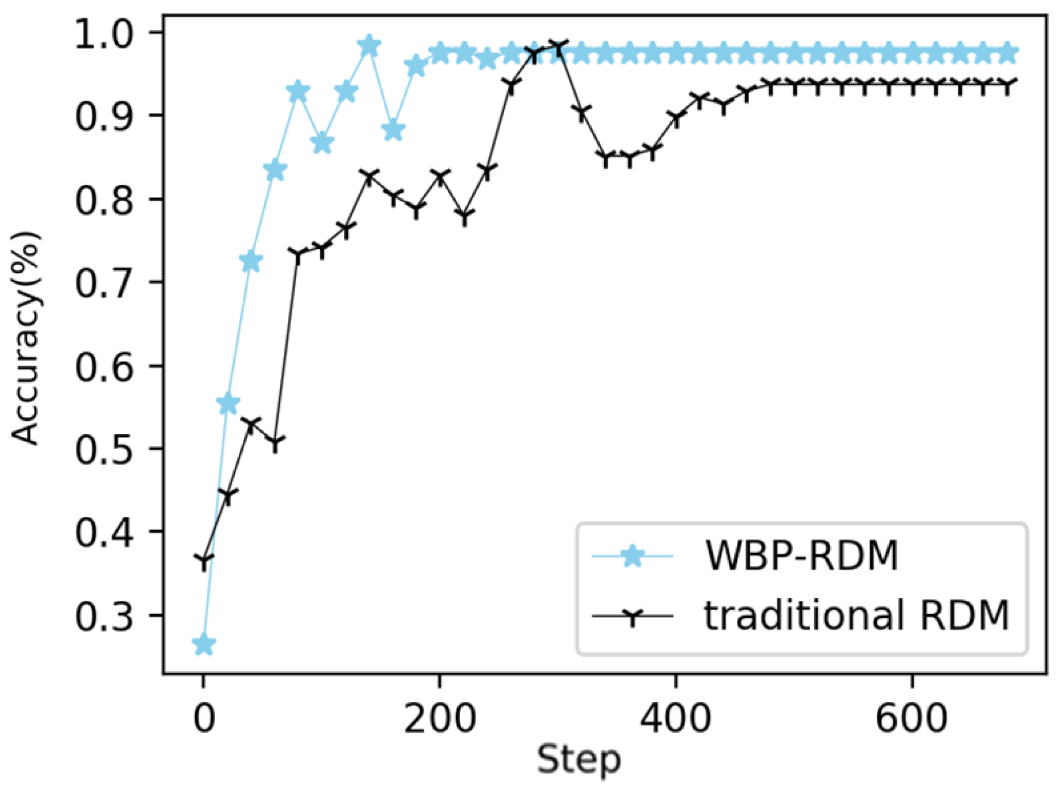
We compared the traditional RDM and improved RDM with windowing and IF-BPF (WBP-RDM) and keep other parts unchanged in order to analyze the impact of preprocessing method of windowing and IF-BPF. The same training and testing processes were carried out. Figure 14 shows the recognition results. As steps increase, both data can converge to a stable accuracy. However, the convergence speed of traditional RDM is much slower than that of WBP-RDM. It can be seen in Figure 13 that traditional RDM converge at step 400, while WBP-RDM reach convergence at step 200. In terms of final accuracy, WBP-RDM achieves an accuracy of 97.66%, showing an improvement of about 3.91% by contrast with traditional RDM with accuracy of 93.75%.

5.5. Impact of Different Networks on Accuracy

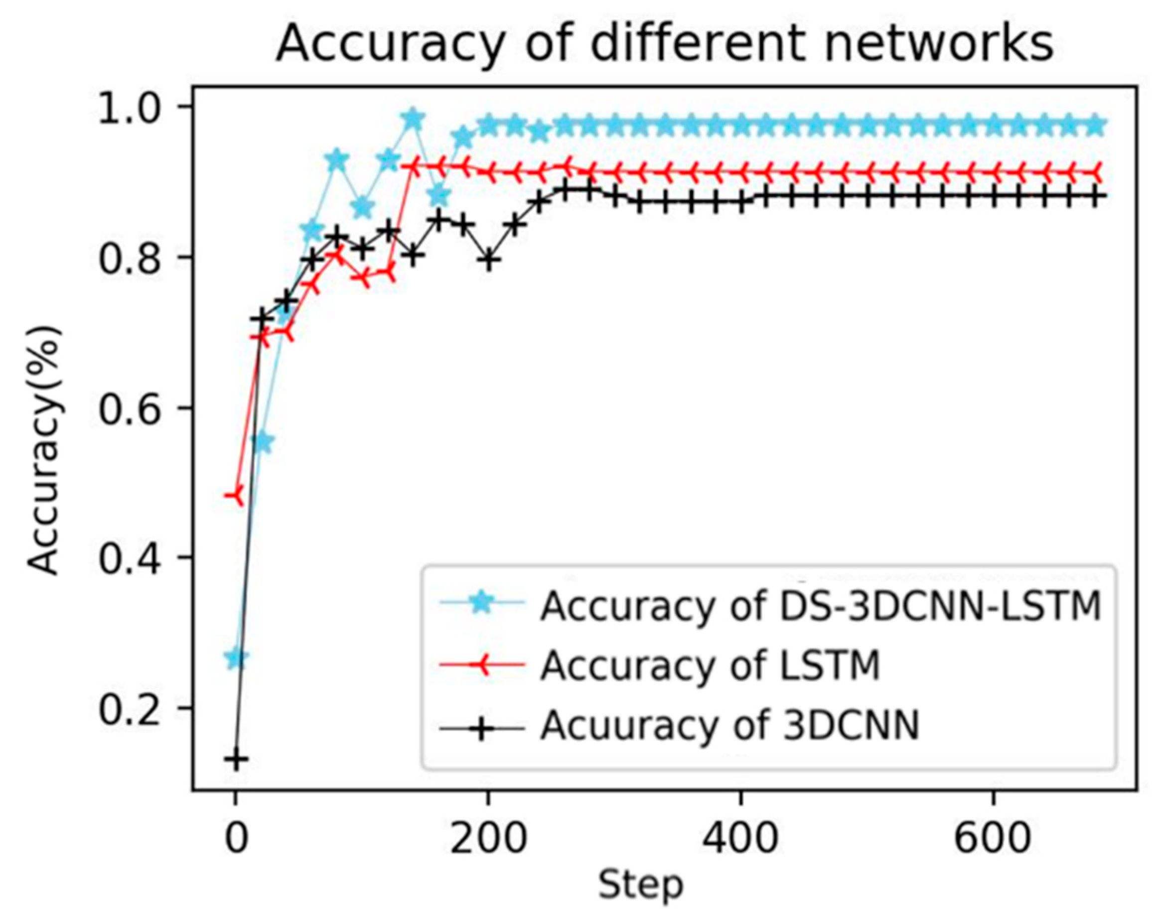
In this work, we combined 3DCNN and LSTM to extract features, and 3DCNNs are employed to learn short-term features and LSTMs are used to learn long features. We compared the accuracy of extracting features using 3DCNN-LSTM and extracting features using only 3DCNN or LSTM in order to verify the validity of the combination of 3DCNN and LSTM. For fair comparison, the structure and parameters of 3DCNN and LSTM are set to be consistent. The experiments are conducted on the same training and testing sets. Figure 15 shows the recognition results of different networks. It is observed that the recognition accuracy of the three networks improved with the increase of steps and accuracy of DS-3DCNN-LSTM is the best, higher than 3DCNN and LSTM. The final recognition accuracy of DS-3DCNN-LSTM, LSTM and 3DCNN are 97.66%, 91.41%, and 88.28%, respectively, which suggests that the combination of 3DCNN and LSTM for the extraction of both short and long term spatial-temporal features is effective for hand gesture recognition.

6. Conclusions

This work proposed a DS-3DCNN-LSTM gesture recognition system based on RDMTS and RAMTS fusion of FMCW MIMO radar. Firstly, a windowed RDM with IF-BPF was presented for hand range and velocity estimation. Secondly, a RFBM 2D joint super-resolution algorithm was proposed in order to generate RAM for range and azimuth estimation. Finally, a DS-3DCNN-LSTM network was presented for the feature extraction and fusion of RDMTS and RAMTS with gesture radial and transversal information preserved. Several comparative experiments were conducted on 10 complex gestures. The Windowed RDM with IF-BPF obtains a 3.91% improvement over traditional RDM, which verifies the effectiveness of presented signal preprocessing method. The dual-stream 3DCNN-LSTM network that is based on the feature fusion of RDMTS and RAMTS achieves better performance than single stream 3DCNN-LSTM. It improves 15.63% than single RDMTS input and 3.69% than single RAMTS input. The average recognition accuracy of the proposed method reached 97.66%, showing that the method can effectively distinguish different gestures.
Future work will consider the interference suppression of human body in more complex scenarios, and focus on the state-of-the-art deep learning network to excavate complex gestures feature.

Author Contributions

Data curation, L.X.; Funding acquisition, W.L.; Methodology, X.J.; Software, L.X., J.L. and M.X.; Supervision, F.H.; Validation, X.J.; Visualization, L.X.; Writing—original draft, X.J.; Writing—review & editing, W.L. and F.H. All authors have read and agreed to the published version of the manuscript.

Funding

This research was funded by National Key R&D Program Safety Guarantee Technology of Urban Rail System under Grant, grant number 2016YFB1200402 and 2017 Hunan-Tech & Innovation Investment Project of China under Grant, grant number 2017GK5019.

Conflicts of Interest

The authors declare no conflict of interest.

References

  1. Deng, M. Robust Human Gesture Recognition by Leveraging Multi-Scale Feature Fusion. Signal Process. Image Commun. 2019, 83, 115768. [Google Scholar] [CrossRef]
  2. John, V.; Umetsu, M.; Boyali, A.; Mita, S.; Imanishi, M.; Sanma, N.; Shibata, S. Real-Time Hand Posture and Gesture-Based Touchless Automotive User Interface Using Deep Learning. In Proceedings of the 2017 IEEE Intelligent Vehicles Symposium (IV), Redondo Beach, CA, USA, 11–14 June 2017; pp. 869–874. [Google Scholar]
  3. Li, X. Human–Robot Interaction Based on Gesture and Movement Recognition. Signal Process. Image Commun. 2020, 81, 115686. [Google Scholar] [CrossRef]
  4. Rautaray, S.S.; Agrawal, A. Vision Based Hand Gesture Recognition for Human Computer Interaction: A Survey. Artif. Intell. Rev. 2015, 43, 1–54. [Google Scholar] [CrossRef]
  5. Almasre, M.A.; Al-Nuaim, H. Recognizing Arabic Sign Language Gestures Using Depth Sensors and a KSVM Classifier. In Proceedings of the 2016 8th Computer Science and Electronic Engineering (CEEC), Colchester, UK, 28–30 September 2016; pp. 146–151. [Google Scholar]
  6. Wu, C.-H.; Lin, C.H. Depth-Based Hand Gesture Recognition for Home Appliance Control. In Proceedings of the 2013 IEEE International Symposium on Consumer Electronics (ISCE), Hsinchu, Taiwan, 3–6 June 2013; pp. 279–280. [Google Scholar]
  7. Gupta, S.; Molchanov, P.; Yang, X.; Kim, K.; Tyree, S.; Kautz, J. Towards Selecting Robust Hand Gestures for Automotive Interfaces. In Proceedings of the 2016 IEEE Intelligent Vehicles Symposium (IV), Gothenburg, Sweden, 19–22 June 2016; pp. 1350–1357. [Google Scholar]
  8. Li, G.; Zhang, R.; Ritchie, M.; Griffiths, H. Sparsity-Based Dynamic Hand Gesture Recognition Using Micro-Doppler Signatures. In Proceedings of the 2017 IEEE Radar Conference (RadarConf), Seattle, WA, USA, 8–12 May 2017; pp. 928–931. [Google Scholar]
  9. Skaria, S.; Al-Hourani, A.; Lech, M.; Evans, R.J. Hand-Gesture Recognition Using Two-Antenna Doppler Radar with Deep Convolutional Neural Networks. IEEE Sens. J. 2019, 19, 3041–3048. [Google Scholar] [CrossRef]
  10. Zhang, S.; Li, G.; Ritchie, M.; Fioranelli, F.; Griffiths, H. Dynamic Hand Gesture Classification Based on Radar Micro-Doppler Signatures. In Proceedings of the 2016 CIE International Conference on Radar (RADAR), Guangzhou, China, 10–13 October 2016; pp. 1–4. [Google Scholar]
  11. Wu, Q.; Zhao, D. Dynamic Hand Gesture Recognition Using FMCW Radar Sensor for Driving Assistance. In Proceedings of the 2018 10th International Conference on Wireless Communications and Signal Processing (WCSP), Hangzhou, China, 18–20 October 2018; pp. 1–6. [Google Scholar]
  12. Sun, Y.; Fei, T.; Schliep, F.; Pohl, N. Gesture Classification with Handcrafted Micro-Doppler Features Using a FMCW Radar. In Proceedings of the 2018 IEEE MTT-S International Conference on Microwaves for Intelligent Mobility (ICMIM), Munich, Germany, 16–17 April 2018; pp. 1–4. [Google Scholar]
  13. Zhang, Z.; Tian, Z.; Zhou, M. Latern: Dynamic Continuous Hand Gesture Recognition Using FMCW Radar Sensor. IEEE Sens. J. 2018, 18, 3278–3289. [Google Scholar] [CrossRef]
  14. Lien, J.; Gillian, N.; Karagozler, M.E.; Amihood, P.; Schwesig, C.; Olson, E.; Raja, H.; Poupyrev, I. Soli: Ubiquitous Gesture Sensing with Millimeter Wave Radar. ACM Trans. Graph. 2016, 35, 1–19. [Google Scholar] [CrossRef] [Green Version]
  15. Wang, Y.; Wang, S.; Zhou, M.; Jiang, Q.; Tian, Z. TS-I3D Based Hand Gesture Recognition Method with Radar Sensor. IEEE Access 2019, 7, 22902–22913. [Google Scholar] [CrossRef]
  16. Choi, J.-W.; Ryu, S.-J.; Kim, J.-H. Short-Range Radar Based Real-Time Hand Gesture Recognition Using LSTM Encoder. IEEE Access 2019, 7, 33610–33618. [Google Scholar] [CrossRef]
  17. Molchanov, P.; Gupta, S.; Kim, K.; Pulli, K. Short-Range FMCW Monopulse Radar for Hand-Gesture Sensing. In Proceedings of the 2015 IEEE Radar Conference (RadarCon), Washington, DC, USA, 10–15 May 2015; pp. 1491–1496. [Google Scholar]
  18. Chung, H.; Chung, Y.; Tsai, W. An Efficient Hand Gesture Recognition System Based on Deep CNN. In Proceedings of the 2019 IEEE International Conference on Industrial Technology (ICIT), Melbourne, Australia, 13–15 February 2019; pp. 853–858. [Google Scholar]
  19. Karpathy, A.; Toderici, G.; Shetty, S.; Leung, T.; Sukthankar, R.; Fei-Fei, L. Large-Scale Video Classification with Convolutional Neural Networks. In Proceedings of the IEEE conference on Computer Vision and Pattern Recognition, Columbus, OH, USA, 24–27 June 2014; pp. 1725–1732. [Google Scholar]
  20. Zhu, F.; Kong, X.; Fu, H.; Tian, Q. A Novel Two-Stream Saliency Image Fusion CNN Architecture for Person Re-Identification. Multimed. Syst. 2018, 24, 569–582. [Google Scholar] [CrossRef]
  21. Molchanov, P.; Gupta, S.; Kim, K.; Kautz, J. Hand Gesture Recognition with 3D Convolutional Neural Networks. In Proceedings of the IEEE conference on computer vision and pattern recognition workshops, Boston, MA, USA, 7–12 June 2015; pp. 1–7. [Google Scholar]
  22. Zhang, W.; Wang, J. Dynamic Hand Gesture Recognition Based on 3D Convolutional Neural Network Models. In Proceedings of the 2019 IEEE 16th International Conference on Networking, Sensing and Control (ICNSC), Banff, AB, Canada, 9–11 May 2019; pp. 224–229. [Google Scholar]
  23. Tran, D.; Bourdev, L.; Fergus, R.; Torresani, L.; Paluri, M. Learning Spatiotemporal Features with 3d Convolutional Networks. In Proceedings of the IEEE international conference on computer vision, Las Condes, San Diego, Chile, 11–18 December 2015; pp. 4489–4497. [Google Scholar]
  24. Zhang, Z.; Tian, Z.; Zhou, M. SmartFinger: A Finger-Sensing System for Mobile Interaction via MIMO FMCW Radar. In Proceedings of the 2019 IEEE Globecom Workshops, GC Wkshps 2019—Proceedings, Waikoloa, HI, USA, 9–13 December 2019; pp. 1–5. [Google Scholar]
  25. Koch, P.; Dreier, M.; Maass, M.; Böhme, M.; Phan, H.; Mertins, A. A Recurrent Neural Network for Hand Gesture Recognition Based on Accelerometer Data. In Proceedings of the 2019 41st Annual International Conference of the IEEE Engineering in Medicine and Biology Society (EMBC), Berlin, Germany, 23–27 July 2019; pp. 5088–5091. [Google Scholar]
  26. Tai, T.-M.; Jhang, Y.-J.; Liao, Z.-W.; Teng, K.-C.; Hwang, W.-J. Sensor-Based Continuous Hand Gesture Recognition by Long Short-Term Memory. IEEE Sens. Lett. 2018, 2, 1–4. [Google Scholar] [CrossRef]
  27. Jian, C.; Li, J.; Zhang, M. LSTM-Based Dynamic Probability Continuous Hand Gesture Trajectory Recognition. IET Image Process. 2019, 13, 2314–2320. [Google Scholar] [CrossRef]
  28. Hamidi, S.; Nezhad-Ahmadi, M.-R.; Safavi-Naeini, S. TDM Based Virtual FMCW MIMO Radar Imaging at 79GHz. In Proceedings of the 2018 18th International Symposium on Antenna Technology and Applied Electromagnetics (ANTEM), Waterloo, ON, Canada, 19–22 August 2018; pp. 1–2. [Google Scholar]
  29. Robey, F.C.; Coutts, S.; Weikle, D.; McHarg, J.C.; Cuomo, K. MIMO Radar Theory and Experimental Results. In Proceedings of the Conference Record of the Thirty-Eighth Asilomar Conference on Signals, Systems and Computers, Pacific Grove, CA, USA, 7–10 November 2004; Volume 1, pp. 300–304. [Google Scholar]
  30. Schmidt, R. Multiple Emitter Location and Signal Parameter Estimation. IEEE Trans. Antennas Propag. 1986, 34, 276–280. [Google Scholar] [CrossRef] [Green Version]
  31. Belfiori, F.; van Rossum, W.; Hoogeboom, P. Application of 2D MUSIC Algorithm to Range-Azimuth FMCW Radar Data. In Proceedings of the 2012 9th European Radar Conference, Amsterdam, The Netherlands, 29 October–2 November 2012; pp. 242–245. [Google Scholar]
  32. Christoph, S.; Jawad, M.; Nossek, M.; Amine, M.; Josef, A.N. DoA Estimation Performance and Computational Complexity of Subspace- and Compressed Sensing-Based Methods. In Proceedings of the 19th International ITG Workshop on Smart Antennas, Ilmenau, Germany, 3–5 March 2015. [Google Scholar]
  33. Roy, R.; Kailath, T. ESPRIT-Estimation of Signal Parameters via Rotational Invariance Techniques. IEEE Trans. Acoust. 1989, 37, 984–995. [Google Scholar] [CrossRef] [Green Version]
  34. Capon, J. High-Resolution Frequency-Wavenumber Spectrum Analysis. Proc. IEEE 1969, 57, 1408–1418. [Google Scholar] [CrossRef] [Green Version]
  35. Stoica, P.; Wang, Z.; Li, J. Robust Capon Beamforming. In Proceedings of the Conference Record of the Thirty-Sixth Asilomar Conference on Signals, Systems and Computers, Pacific Grove, CA, USA, 3–6 November 2002; Volume 1, pp. 876–880. [Google Scholar]
  36. Wang, Y.; Jiang, Z.; Gao, X.; Hwang, J.-N.; Xing, G.; Liu, H. RODNet: Object Detection under Severe Conditions Using Vision-Radio Cross-Modal Supervision. arXiv 2020, arXiv:2003.01816. [Google Scholar]
  37. Major, B.; Fontijne, D.; Ansari, A.; Sukhavasi, R.T. 2019 I. I. C. on C. V. W. In Proceedings of the Vehicle Detection With Automotive Radar Using Deep Learning on Range-Azimuth-Doppler Tensors, Seoul, Korea, 27–28 October 2019. [Google Scholar]
  38. Dongmei, L.; Peng, Z.; Yigang, H. Analysis and Comparison of Several Harmonic Detection Methods with Windowed and Interpolation FFT. Electr. Meas. Instrum. 2013, 50, 51–55. [Google Scholar]
  39. Farina, A.; Studer, F.A. A Review of CFAR Detection Techniques in Radar Systems. Microw. J. 1986, 29, 115. [Google Scholar]
  40. Ioffe, S.; Szegedy, C. Batch Normalization: Accelerating Deep Network Training by Reducing Internal Covariate Shift. arXiv 2015, arXiv:1502.03167. [Google Scholar]
  41. IWR1443 Evaluation Module (IWR1443BOOST) mmWave Sensing Solution User’s Guide. Available online: http://www.ti.com.cn/tool/cn/IWR1443BOOST/ (accessed on 6 April 2019).
  42. DCA1000EVM Data Capture Card User’s Guide. Available online: http://www.ti.com.cn/tool/cn/IWR1443BOOST/ (accessed on 6 April 2019).
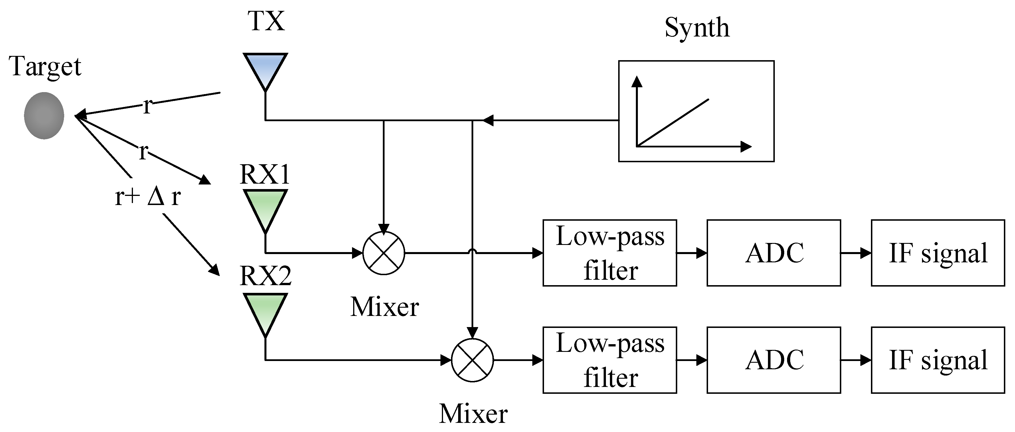
Figure 1. The overview of hand gesture recognition system.
Electronics 09 00869 g001
Figure 2. Simplified structure of radar sensor.
Electronics 09 00869 g002
Figure 3. The generation of virtual array: (a) MIMO radar with two transmit antennas and four receive antennas. (b) Virtual array of eight receive antennas.
Electronics 09 00869 g003
Figure 4. Range–Doppler FFT calculation process to generate a traditional Range–Doppler Map (RDM).
Electronics 09 00869 g004
Figure 5. RDMs of different operations: (a) traditional RDM after Range Doppler FFT; (b) RDM after Windowing; and, (c) improved RDM after windowing and IF band pass filter.
Electronics 09 00869 g005
Figure 6. Block diagram of proposed IF-BPF algorithm.
Electronics 09 00869 g006
Figure 7. Range Azimuth Maps (RAMs) of target at different angular positions: (a) RAM of target at −20°. (b) RAM of target at 0°. (c) RAM of target at 20°.
Electronics 09 00869 g007
Figure 8. An overview of DS-3DCNN-LSTM network. Part A: 3DCNN structure; Part B: Long Short Term Memory (LSTM) structure; Part C: feature fusion; Part D: classification.
Electronics 09 00869 g008
Figure 9. Radar signal data acquisition module.
Electronics 09 00869 g009
Figure 10. Gestures considered in the experiments. (a) CW: Clockwise; (b) CCW: Counter Clockwise; (c) DV: Drawing V; (d) DVV: Drawing verse V; (e) PS: Push; (f) PL: Pull; (g) PSPL: Push and Pull; (h) PLPS: Pull and Push; (i) SRL: Sliding Right to Left; and, (j) SLR: Sliding Left to Right.
Electronics 09 00869 g010
Figure 11. Traditional RDMs without windowing and IF-BPF of a push hand gesture. (a) Traditional RDM of frame 1. (b) Traditional RDM of frame 7. (c) Traditional RDM of frame 12. (d) Traditional RDM of frame 22. (e) Traditional RDM of frame 28.
Electronics 09 00869 g011
Figure 12. Improved RDMs with windowing and IF-BPF of a push hand gesture. (a) Improved RDM of frame 1. (b) Improved RDM of frame 7. (c) Improved RDM of frame 12. (d) Improved RDM of frame 22. (e) Improved RDM of frame 28.
Electronics 09 00869 g012
Figure 13. RAMs of a sliding left to right hand gesture. (a) RAM of frame 1. (b) RAM of frame 6. (c) RAM of frame 11. (d) RAM of frame 20. (e) RAM of frame 30.
Electronics 09 00869 g013
Figure 14. Accuracy of different types of RDMs.
Electronics 09 00869 g014
Figure 15. Accuracy of different networks.
Electronics 09 00869 g015
Table 1. Parameters Configuration of frequency modulated continuous wave (FMCW) radar.
ParameterSymbolValue
Carrier frequency f c 77 GHz
Bandwidth B 4 GHz
Time window T c h i r p 100 μs
Idle Time between chirps T i d l e 100 μs
Wavelength λ 3.90 mm
Transmitting antenna distance d t 7.8 mm
Receiving antenna d r 1.9 5 mm
Number of Frames F r a 30
Number of chirps in a frame C h p 128
Samples in one chirp S p 512
Frame period T p 80 ms
Table 2. Confusion matrix of 10 types of hand gesture.
GesturesCWCCWDVDVVPLPLPSPSPSPLSLRSRL
CW0.9440.000.000.000.000.000.000.000.000.056
CCW0.001.0000.000.000.000.000.000.000.000.00
DV0.000.000.8570.1430.000.000.000.000.000.00
DVV0.000.000.001.0000.000.000.000.000.000.00
PL0.000.000.000.001.0000.000.000.000.000.00
PLPS0.000.000.000.000.1110.8890.000.000.000.00
PS0.000.000.000.000.000.001.0000.000.000.00
PSPL0.000.000.000.000.000.000.001.0000.000.00
SLR0.000.000.000.000.000.000.000.001.0000.00
SRL0.000.000.000.000.000.000.000.000.001.000
Table 3. Recognition Accuracy Comparison of Different Training Strategies.
Training StrategyModalityAccuracy
Strategy 1RDMTS only82.03%
Strategy 2RAMTS only93.97%
Strategy 3RAMTS + RDMTS97.66%