Article

Design of a Projectile-Borne Data Recorder Triggered by Overload

School of Mechanical Engineering, Nanjing University of Science & Technology, Nanjing 210094, China
*
Author to whom correspondence should be addressed.
Electronics 2020, 9(5), 860; https://doi.org/10.3390/electronics9050860
Submission received: 15 February 2020 / Revised: 18 May 2020 / Accepted: 19 May 2020 / Published: 22 May 2020
(This article belongs to the Section Computer Science & Engineering)

Abstract

:
The projectile-borne data recorder is used to measure and record the position and attitude data of exterior ballistic flights, which experience high overload during the launching process. The navigation algorithm can be optimized by analyzing the data stored in the recorder. As the primary means of acquiring the navigation data, the micro inertial measurement unit (MIMU) is an inevitable part of the projectile equipment. However, its mechanical structure could hardly bear the high overload during operation. In view of the above problems, a novel projectile-borne data recorder triggered by overload is designed in this paper. The recorder could have the navigation system powered when the projectile leaves the barrel so as to activate the data recording of the high overload. Furthermore, the viability of the MIMU of the high overload is guaranteed through a specific way of system encapsulation. In the proposed design, the overload switch redundancy and the power supply redundancy were adopted to improve reliability. The proposed design is tested with practical experiments, and the results show that the proposed recorder could be effectively triggered by overloading, and the supply voltage is stable, which helps record reliable data for the projectile.

1. Introduction

The intelligent projectile is amongst the guided weapons that are fired by an artillery and strike the target accurately through searching, guidance and control during flight [1]. In flight, it is crucial to measure the attitude angles, namely the heading, pitching, rolling, in real time. Use in the EX-171 extended range guided munition [2], the combination of the micro inertial measurement unit (MIMU) and GPS, is a popular scheme for attitude measurement and control [2,3], where the MIMU constituting of the tri-axial accelerometers and gyroscopes, is a sensor unit for measuring acceleration, tilt, impact, vibration, rotation.
As micromechanical inertial sensor has etch-moveable structures on silicon wafers, working in the impact environment is great challenge for the MIMU [4]. In particular, the spacing of the comb tooth structure is very small (about 10 µm) in the high-precision micro electro-mechanical systems (MEMS) gyroscope, and there would be resonant vibration with high frequency and large amplitude (1–3 µm) in the comb tooth structure when the power is on, so the device is more likely to fail under great impact [5]. For the projectile, the impact acceleration is large, with an intensity of more than 15,000 g and a duration of more than 10 ms during the launch phase [6]. In this circumstance, there are two outstanding problems, one is that the MIMU is easy to be damaged under the big impact, resulting in incapability of the inertial sensors; the other one is that the experimental data is needed for postanalysis and system improvement on the basis of the proper operation of the sensors. In order to ensure the working reliability of the MIMU, researchers and engineers all over world have completed various studies to solve the above-mentioned two issues. For the first issue, it can be improved through the optimal design of the gyro structure [7,8,9,10,11], like the optimal design of the folding beam [9,10] and the limit structure design of the mass block [8], etc. Such measures can only ensure its reliable operation in the state of no power, and cannot guarantee the normal operation of the device in the case of power [10]. For the second issue, there are three main methods to obtain the flight data of the projectile. One is the external measurement method [12,13], which measures the projectile speed with the external equipment of the projectile, such as a high-speed camera [12], Doppler radar [13] and so on. Since the external measurement method relies on the external equipment of the shooting range, and the rotational speed is also calculated off the projectile, it cannot implement the autonomous measurement or guidance for the projectile. The second method is the telemetry [14], which refers to the installation of a rate sensor on the projectile, and the flight speed information is sent to the ground station over transmission. The problem with telemetry [14] is the great cost of the equipment installation and debugging and transmission. The third method is to equip a recorder in the projectile. Compared with external measurement and the telemetry, the flight recorder [15,16,17,18,19,20] uses the onboard sensor to measure the flight data instead of external equipment, which is a direct and low-cost way to obtain real-time data.
This paper aims to design a flight recorder for the projectile, to not only record the miniature inertial measurement unit (MEMS-IMU) data in real time, but also protect the MEMS-IMU from being damaged under the great impact. The proposed design is a FLASH-based recording device which is enabled by overload so as to delay power-on of the MIMU and avoid the impact damage on the sensors. Furthermore, the proposed recorder is marked with redundancy design in improving the system reliability. On one hand, a power supply scheme of a redundant parallel farad capacitor for dual lithium batteries is designed to guarantee the delayed power-on function and to alleviate the dropping of the power supply voltage of lithium battery issues in the projectile firing stage. One the other hand, as the delayed power-on function of the recorder is dependent on the detection of the overload, the record is redundant with two overload detection schemes, namely, the mechanical switching mode, and the electronic switching mode based on the accelerometer to enhance the overload-detecting reliability. In addition, in order to further protect the system, the strength is increased by means of epoxy resin sealing. Finally, the function of the proposed design is verified by laboratory experiments and practical projectile tests.
The organization of this paper is as follows. The overall design scheme is given in Section 2. Then, Section 3 presents the detail of the hardware, including the data recording module, the impact detection module, the power supply module, etc. The laboratory experiments on the recorder’s functions and the projectile tests with a detailed analysis are presented in Section 4. Section 5 concludes the paper.

2. Design Scheme

The block diagram of the designed recorder is shown in Figure 1. It is mainly consisted of three modules, the overload detection module, the recording module and the power supply module. The performance of the recorder is verified by the MIMU. The working process among modules is detailed below.
(1)
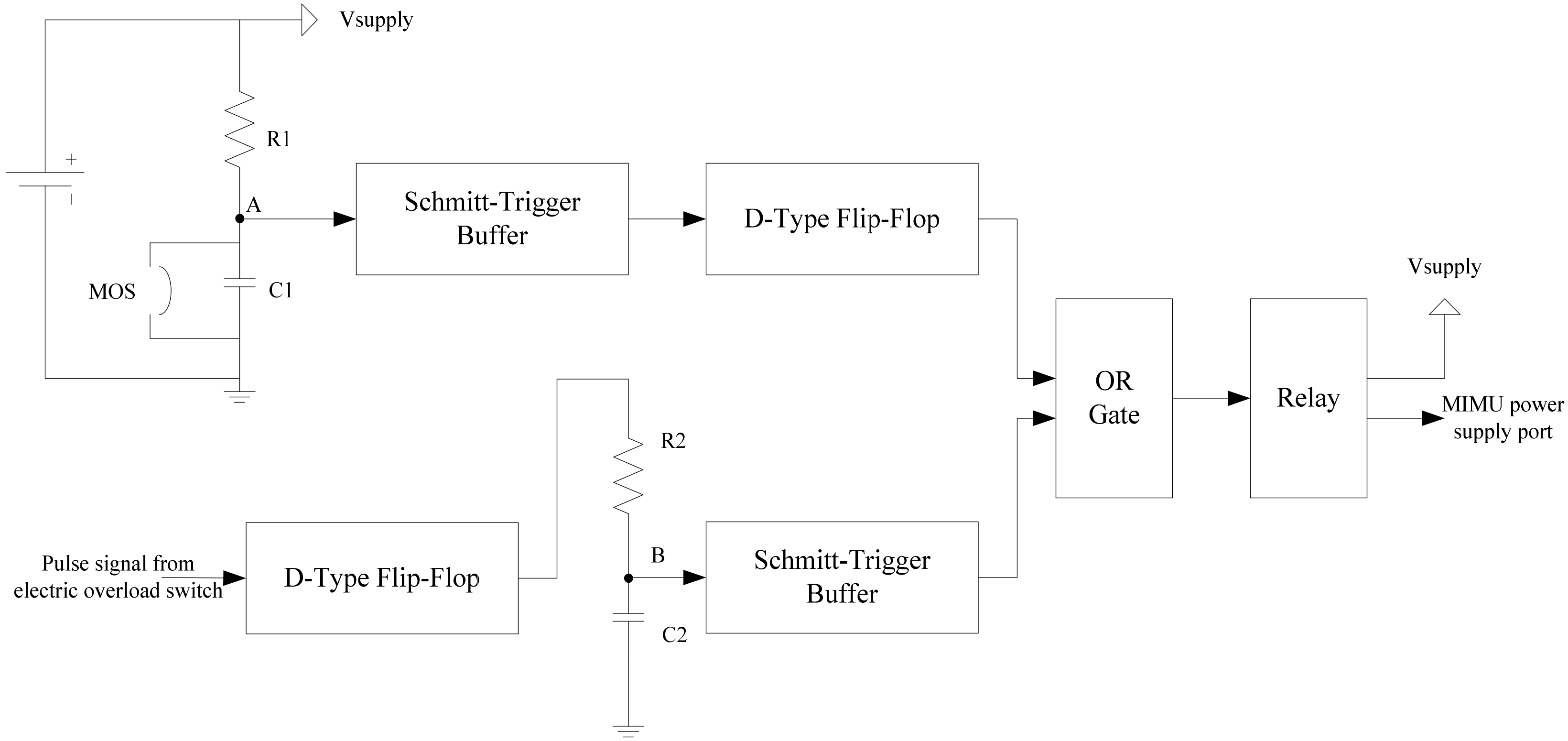
The power supply module only supplies the overload detection module and the recording module at the beginning. If an impact acceleration of certain magnitude is detected in the overload detection module, a trigger signal is created and goes through the delay circuit to relay and supply power to the MIMU. The delay time is determined based on specific requirements.
(2)
The data recording module constitutes of the data interface unit, the processor and the nonvolatile data storage unit. The data interface receives the MIMU measurement through RS422, and sends data to the processor via bus. The processor records the sensor data into the nonvolatile storage unit through serial peripheral interface (SPI) bus.
(3)
After the experiment, the experimental data is read back from the nonvolatile memory of the processor, and sent to the computer through RS422.

3. Hardware Design

3.1. Data Recording Module

3.1.1. Processor STM32

As the core of the projectile-borne recorder, the processor is responsible for data storage and reading. Considering the performance and programming simplicity of the processor, STM32F411 is selected as the main control unit [21,22]. The processor has the following characteristics:
  • It uses ARM’s 32-bit Cortex™-M4 core, which has better performance than other processor chips;
  • The working frequency is up to 168 MHz, and the processing speed is fast;
  • Floating-point calculation can be carried out;
  • Internal integrated digital signal processing (DSP) instruction set, and the development speed is fast;
  • Large storage space, and strong expansion of storage space;
  • Rich peripherals, with no separate design of external drive;
  • Internal integrated hardware debugging function, so it is convenient to check the internal status during debugging;
  • Cyclic redundancy check (CRC) computing unit, power monitoring controller, watchdog timer, clock controller and other highly integrated.

3.1.2. Nonvolatile Storage Unit

The memory module is mainly used to record all kinds of parameters in the process of projectile flight [23,24,25,26,27,28,29,30], which requires large storage, fast storing speed and stable performance, and as such, Nor Flash is selected for storage. Compared with the parallel interface Nor Flash, SPI interface Nor Flash has the advantages of small size, simple interface and ease of use, making it especially suitable for a compact application environment. In this research, the Micron Technology Inc’s Nor Flash—N25Q00AA is employed, with the Flash of 1 Gb storage capacity, and it is supported by SPI serial port communication as fast as 108 MHz. Furthermore, it can read/be written per page at 256 bytes in 0.5–5 ms.

3.1.3. Data Storage Operation

The data storage module reads the data from MIMU and sends it to the nonvolatile storage unit. For the 32 bytes data of 1 kHz output rate, the storage of 1 Gb capacity can store about 70 min of the experimental data. That is to say, in 1 ms, the processor needs to read 32 bytes data via RS422 and store them in one page of Flash. If rate of RS422 is 460,800 bps, the read time of 32 bytes data is about 0.7 ms, and the time to store one page in Flash is 0.5 ms. It will be over 1 ms for an update within the serial operation which would result in chaos of the data storing. Regarding this problem, the interrupt receiver using the serial port direct memory access (DMA) and “ping pong” storage have been adopted in this paper.
On one hand, the microcontroller is set to the serial DMA interrupt mode. When the serial port receives 32 bytes data, an overflow interrupt is generated, and the microcontroller is transferred to the interrupt program for processing. On the other hand, two data cache areas with 256 bytes are created, namely buffer A and the buffer B, respectively. When the serial port receives the data, it is firstly stored in buffer A. When buffer A is full, the microcontroller sends the data to buffer B. Flash receives data from SPI and writes it to page one. This approach greatly reduces the use of the CPU, allowing it to complete some additional calculations, which is also an improvement in the Flash storage unit utilization.

3.2. Impact Detection Module

In this paper, two sensors are used to detect the impact acceleration. One is the mechanical overload switch that uses the inertia of the mass block to cut off the wire during impact and create an on/off signal; the other one is the electronic overload switch with a wide-range acceleration sensor, which is used when the output of the acceleration sensor exceeds a designed threshold to give an on/off signal.

3.2.1. Mechanical Overload Switch

The mechanical overload switch adopts a typical “spring-mass” structure, which is composed of mass block, spring, guide sleeve, driving mechanism, contacting mechanism and so on. If the mass block detects an acceleration overload, by acceleration overload, the mass block makes a movement to generate a displacement and inertia force (F = ma), to compress the spring, overcome the friction force, and reverse the force of the contacting mechanism. The structure of the contacting mechanism is pushed to complete the conversion of the output of the overload signal. The structure of the mechanical overload switch is shown in Figure 2.
In Figure 3, the shell and the central cylindrical structure act as the guide sleeve, which plays the role of concentrating the impact overload in one direction. The pushing mechanism adopts the shear pin structure. The output mechanism is a metal wire fixed at both ends. In the normal state, the metal wire is conducting. Under the impact of the overload, the pin will be cut off and disconnected. According to the mechanical analysis, the shear force is proportional to the mass of the block and the tensile strength of the spring. The metal wire is the resistance of the system, and all of the mechanisms work together to ensure the overload switch avoids a false alarm of small impact conditions. In this research, the mass block of the mechanical overload switch is 12 g, the spring has a wire diameter of 1 mm, an outer diameter 8 mm, 15 turns, and a height of 35 mm. The spring is made of 65 Mn steel and the elastic coefficient k is about 2200 N/m. The wire for output is made of AWG20 copper with a 0.52 mm inner diameter. The overall view of the mechanical overload switch is shown in Figure 3.
In brief, the mechanical overload switch would make a state transition from “on” to “off” if an impact was detected.

3.2.2. Electronic Overload Switch

The electronic overload switch senses the impact acceleration with the accelerometer, and compares the value with threshold. It gives the high level if the detected impact acceleration exceeds the threshold, otherwise it gives a low-level signal. In this paper, ADXL1004 of ADI is employed as the acceleration sensor, whose range is −500–500 g. It can survive within as much as 10,000 g impact. When the detected impact acceleration exceeds 1000 g, it outputs a high level, otherwise it outputs a low level. Furthermore, due to possible larger impact, a protective case of stainless steel was designed, and vacuum sealing is operated for the system because the sealing adhesive has certain elasticity that could act as a buffer to alleviate the impact on the accelerometer.
To sum up, if an impact was detected, the electronic overload switch would output a pulse signal, whose width is the period when the impact is greater than 1000 g.

3.2.3. Signal Conditioner

For the two means of detecting impact as mentioned above, the difference lies in that the mechanical overload switch provides on/off signals, while the electronic overload switch gives a pulse signal. For which, a signal conditioning circuit is needed and designed to transform the pulse signal to control the signal for the relay. The relay stays disconnected if impact was not detected, and vice versa.
Figure 4 shows the circuit diagram of the signal conditioner. The upper part is the diagram of the mechanical overload conditioning circuit, and lower one is the electronic overload conditioning circuit. For the upper part, MOS is short for mechanical overload switch, and when no overload is detected, it outputs a low-level signal at point A. Otherwise, the overload impact cuts the lead, Vsuppy powers C1 through R1, and the voltage at point A varies from low to high. Then the Schmitt trigger reshapes the shifted signal by converting it to a digital signal, which formulates the mechanical overload switch trigger signal after D flip-flop. For the lower part, when the overload is detected, the switch outputs a high-level signal, which works to charge C2 through R2. At point B, the signal shifts from low level to high level. The shaped signal is reshaped by the Schmitt trigger as the output signal of the electronic overload switch. Following this, the two reshaped signals go through the “or” and create the control signal of the relay. The relay is closed, and the MIMU is powered by Vsupply.
The RC delay circuit is composed of same resistors and capacitors in both upper and lower circuits. The delay time is related to the values of resistance and capacitance. To improve the detection capability of the overload, an “or” logical operator is used to deal with the two indicating signals, that is, if an overload has been detected in any of the two switches, the relay would be closed and the MIMU powered.

3.3. Power Module

Lithium battery has the advantages of high energy density, small volume, high-rated voltage and low self-discharge rate, which is suitable for limited volume applications. We have chosen the square lithium-ion polymer rechargeable cell to supply power for the recorder. The lithium-ion battery is of 3.7 V voltage, 4.2 V maximum charge voltage, and 1800 mAh nominal capacity. When the MIMU is powered, the supply current is about 500 mA, which means that a lithium battery can supply 3.6 h of power. Of course, the capacity of the battery can supply a reliable power within the long enough duration for the experiment. Nowadays, some researches have been carried out on the performance variation of lithium batteries under impact condition. The research results show that the stability of the long and wide surface of the lithium battery is worse than that of the long and high surface when it is impinged. Therefore, the height direction of the lithium battery is set to be opposite to the impinged direction during installation. Besides, considering the voltage drop of the lithium battery under impact, a redundancy design with two sets of lithium batteries is adopted in this paper.
Furthermore, the voltage of charging the farad capacitor is less affected by the impact, and has low energy density, and as such, in the lithium battery redundancy design, a farad capacitor is connected in parallel. When the lithium battery voltage decreases, the farad capacitor discharges to supply for the overload detection module and the signal conditioning module in the case of a voltage deficiency emergency. The farad capacitance selected in this design is 5 F. The diagram of redundancy design of the battery pack is shown in Figure 5.
As shown in Figure 5, the lithium battery Li1, Li2 and C are powered in parallel, and the Schottky diodes D1, D2 and D3 are used to avoid the back-charging current if damage occurs to the lithium battery under impact. R is the charging-current limiting resistance of the farad capacitor. In addition, two sets of lithium batteries are equipped with charging chips respectively, to make the recorder reusable. Vsupply is connected to the supply port through a relay, which is controlled by the overload detection module. In order to adapt to the various supply voltage of MIMU, an AD–DC conversion module with adjustable output voltage is added between the supply port and MIMU.

3.4. Vacuum Sealing

To further protect the assemble recorder from great impact, vacuum sealing with epoxy resin adhesive is poured to the system [31,32,33], as the cavities in the system might result in the failure of devices like falling off, collision, fracture, shear under great impact. The vacuum sealing process is as follows: After the screening of the systems, the selected systems are placed in the designed cases of stainless steel, the up direction of lithium batteries is aligned with the impact direction, the cavity of the cased is filled with epoxy resin adhesive, and the vacuum operation is carried out to avoid the bubbles. Practical tests demonstrate that the vacuum sealing can effectively protect the circuit and battery from being damaged in the process of impact.

4. Experiments and Results

In this paper, the laboratory experiments and practical projectile test are carried out to verify the performance of the designed recorder. Firstly, the Machete hammer is used in the laboratory to generate the impact acceleration so as to simulate the projectile launching circumstance, in which, the supply stability of the power supply module, the reliability of the impact detection and the effectiveness of the recording function are validated. On this basis, it is proved that the overload delay electrifying can effectively protect the MIMU from being damaged by impact. Secondly, the designed recorder was installed in a projectile and tested in a physical launching process, the recorded flight data of the projectile demonstrates the success of the proposed design.

4.1. The Machete Hammer Experiment

The Machete hammer is a device to simulate the gun-launched process and produce a large impact [34]. The device is mainly composed of the hammer, handle, auxiliary tools, frame and other parts. Because the structure of Machete hammer is specially designed, the impact acceleration of Machete hammer relates to the number of teeth on the Machete hammer, so that the acceleration value at trike can be calculated by the number of teeth on the hammer. This method is easy to operate and has a low cost [34]. The Machete hammer used in the test is shown in Figure 6.

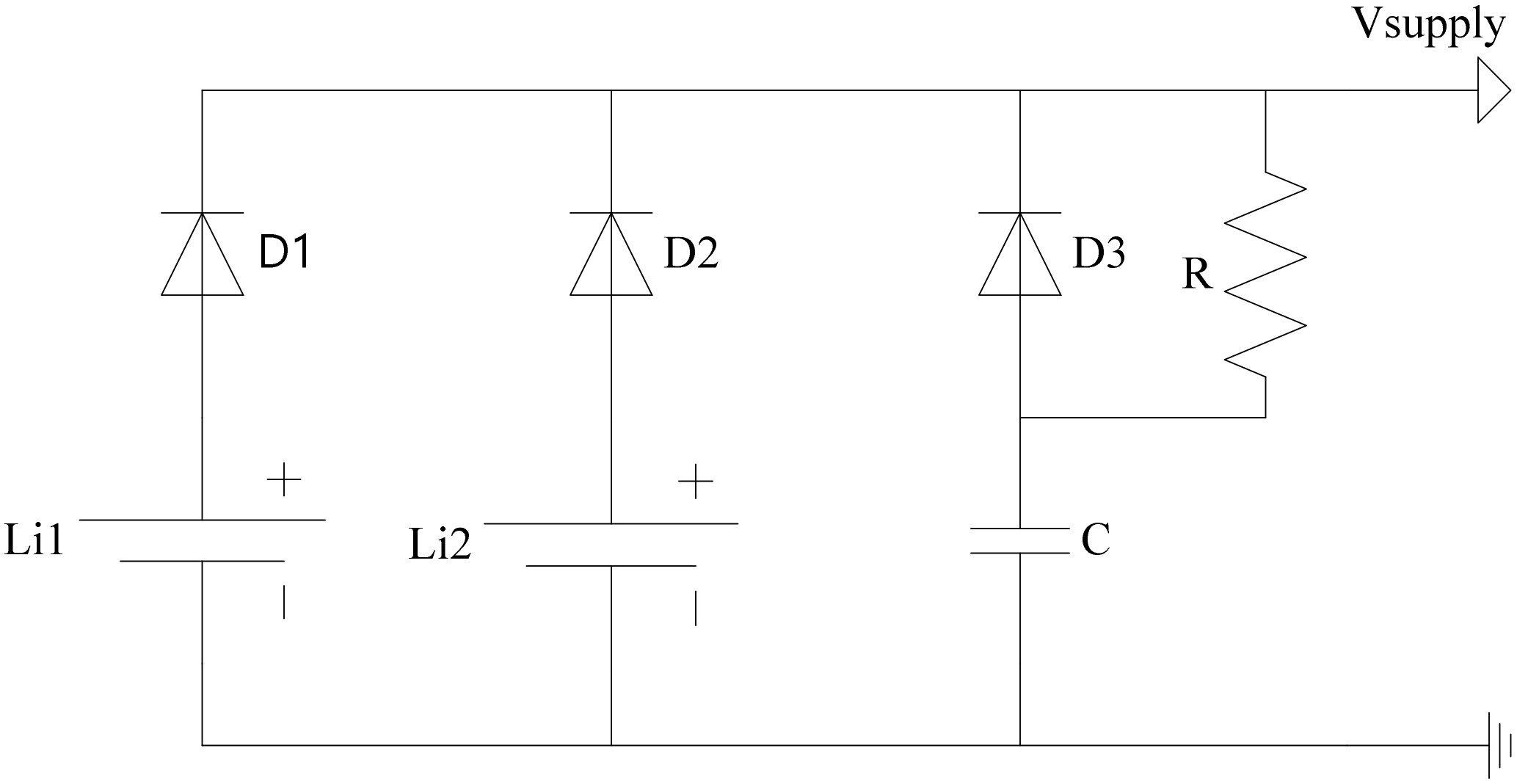
4.1.1. Power Parallel Scheme Verification

The power supply system was manually powered on in the laboratory, and the Machete hammer test was carried out under the conditions of large capacitance disconnected and connected, respectively. In this test, the parallel capacitor is a farad capacitor with a capacitance of 5 F. When the farad capacitor is disconnected, the parallel voltage of the two lithium batteries falls down to 2.5 V from 4.1 V within the impact produced by the Machete hammer. The waveform was more stable after the capacitor was connected, and the falling voltage is only 0.2 V. Because of the trigger circuit, the delay circuit and the accelerometer circuit mention-above are all powered by the parallel circuit. If the impact causes a great large voltage falling, the switch may fail to function. The test results show that the scheme of parallel connection of the lithium battery and capacitor can maintain a stable voltage and guarantee the reliability of power supply under a high overload.

4.1.2. Reliability Verification of the Overload Switch

In this experiment, the status of the mechanical switch and the accelerometer switch are evaluated under different impact conditions induced by the Machete hammer. Different tooth numbers of the Machete hammer correspond to different impact strength. In the projectile-launch test, the overload is about 15,000 g. In the design of the overload switch, the overload trigger thresholds of the accelerometer switch and mechanical switch are about 10,000 g and 13,500 g, respectively. To facilitate the observation and recording, an LED lamp was added in the circuit to identify whether the overload switch is laid on. Table 1 presents the closure condition of the overload switch under different tooth numbers. As shown in Table 1, the accelerometer switch is easier to be turned on than the mechanical switch. The two type of switch cannot be triggered when the impact acceleration is less than 9500 g. This illustrates that the storage system would not be accidentally triggered by turbulences in transportation and redundant design of two-type switches increases the reliability. Through comparable data analysis, the reliability of the overload switch design is verified.

4.1.3. Integrated Test

In the integrated test, two sets of MIMU were tested, set one was equipped with the proposed design, and the other set was not. The necessity of the overload trigger is verified through the outputs of the MIMUs.
In set one, a sealed MIMU was directly fixed on the Machete hammer. At the starts of the test, the MIMU was powered on. With the increasing teeth number of the Machete hammer, the impact grows. It was found that the impact of a Machete hammer with 15 teeth would cause the abnormal output of the MIMU and even caused the uniaxial gyro to break. This test proved that the enabled MIMU could not survive the high overload after electrification, and also proved the necessity of delayed electrification.
In the other set, the tested MIMU is connected with the proposed data recorder, to test the delayed power-on function of the MIMU. The delay time is set to 1 s through the RC circuit. Furthermore, in order to quantitatively describe the impact magnitude, a charge-type impact sensor was installed on the Machete hammer together with an MIMU and data recorder. Its analogous output was collected through a high-speed data acquisition card in 500 kHz. The sample time of the card and the storage system was synchronous through a sync signal. Figure 7 shows the impact curve with 17 Machete hammer teeth. It can be observed that the width of the impact pulse was 500 μs, and the maximum impact was as high as 30,000 g.
Figure 8 shows the synchronization between the NI acquisition card and the data record. It can be seen that the data recorder began to collect the output of the MIMU about 0.95 s after the impact was detected, and that the pulse collected by the impact sensor indicates the occurrence of the impact. The recorder recorded the data of the MIMU sensor under the impact condition, which proved that the delayed power-on was effective. Furthermore, as shown in Table 2, the MIMU’s performance before and after the impact were compared. It can be seen that the MIMU’s outputs did not have a significant difference before and after the impact, and this phenomenon illustrates the necessity of power-on delay.

4.2. Launch Test

Finally, we completed a practical test with a projectile launch to test the proposed design. The procedures were:
  • Before the test, the MIMU and the data recorder were fixed and sealed in the stainless-steel case, against the high overload. Then, the case was installed in the fuse chamber of the experimental projectile.
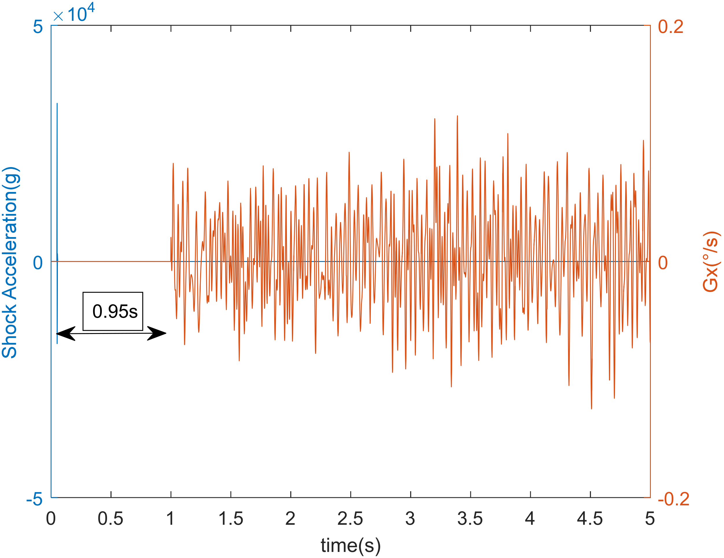
  • Before the launch, the overload-triggering circuit and the delay circuit were enabled, but not the MIMU—that is, the overload detection was initiated.
  • The projectile was launched. The designed recorder was supposed to have the MIMU powered for 1 s after the projectile left the barrel and collect the MIMU’s output in its storage.
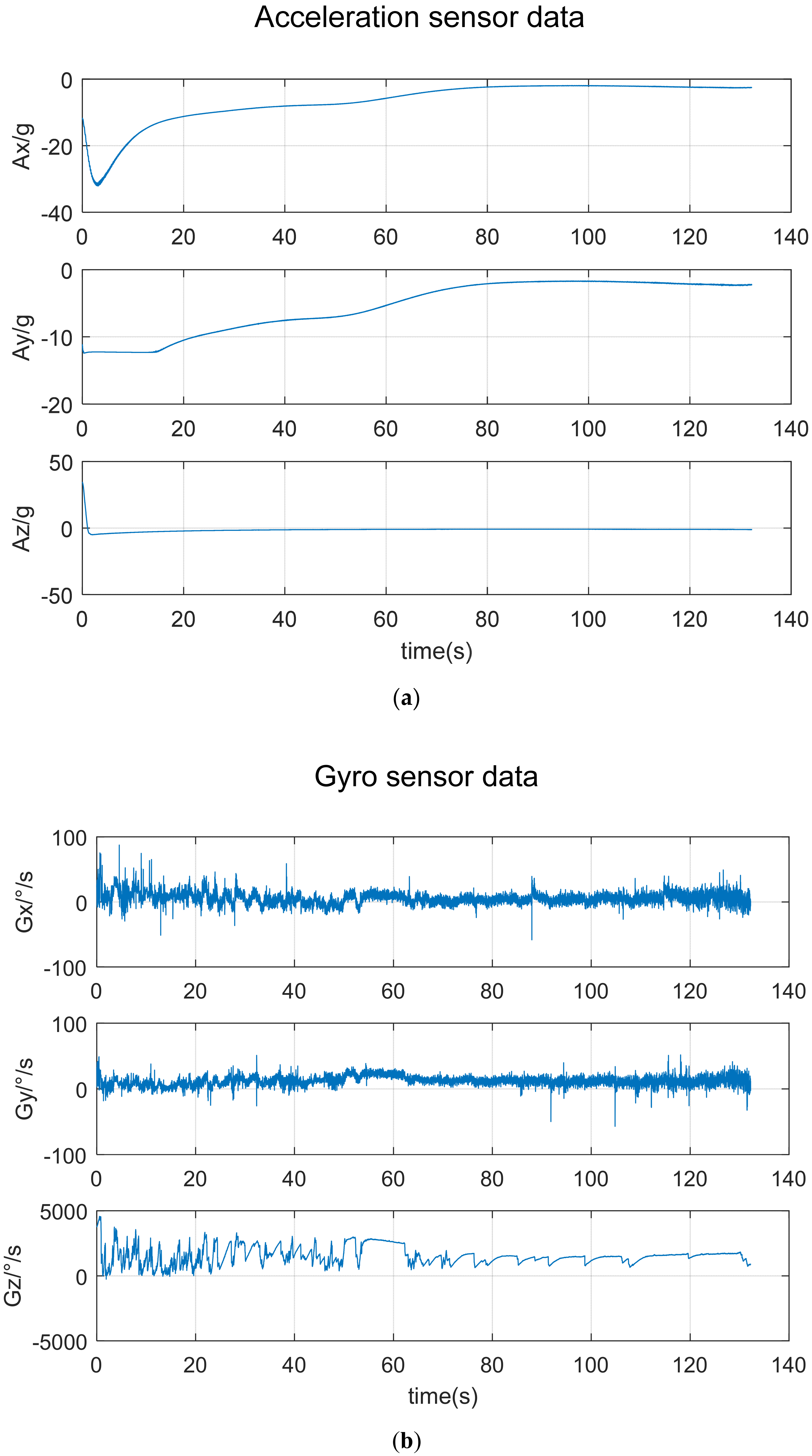
  • The landed projectile was found and the data from the recorder was read.
Figure 9 shows the recorded data of the three-axis gyros and accelerometers from the FLASH.
During the launch, the barrel pressure was 375.1 Mpa, and the overload was about 16,000 g. As shown in Figure 9b, the output of the z-axis gyro Gz reached 5000 °/s after launch, demonstrating the high-speed rotation of the projectile. In addition, the signal curves in Figure 9b reveal the irregular periodic characteristic on three-axial gyro-outputs, which is the typical nutation feature of the projectile flight. From the recorded data, the effectiveness and superiority of the proposed high overload data recorder have been fully validated.

5. Conclusions

This paper presents a projectile-borne data recorder that is triggered by overload. This design makes use of the mechanical switch and the accelerometer switch, to enable the MIMU after the projectiles leaves the barrel, so as to protect the inertial sensors. The scheme of parallel connection of the lithium battery and large capacitance ensures the reliability of power supply voltage for the system. The reliability of the overload switch and accuracy of the projectile-borne recorder are eventually verified through the Machete hammer test and projectile launch test. The available recorded data demonstrates that the design could successfully record the output of the MIMU in a high overload environment. With the recorded inertial data of gyros and accelerometers, the dynamic motion and attitudes of in-flight projectiles could be analyzed to provide instructions for guidance and system optimization.

Author Contributions

Z.W. and Y.W. put forward the method of power on overloading, designed the overload switch and circuit, and compiled the whole program; Z.W., Y.W. and F.Y. conducted simulation, experimental verification and the subsequent data analysis and review; Z.W. and L.Z. wrote the whole paper; Z.W. and L.Z. reviewed and edited the paper. All authors have read and agreed to the published version of the manuscript.

Funding

This work is supported by National Natural Science Foundation of China, No. 61803203.

Conflicts of Interest

The authors declare that they have no conflicts of interest to report regarding the present study.

References

  1. Shang, J.Y.; Deng, Z.H.; Fu, M.Y.; Wang, S.T. Advance and Perspective on Spin Rate Measurement Technology for Guided Projectile. Acta Autom. Sin. 2016, 42, 1620–1630. [Google Scholar]
  2. Dowdle, J.R.; Thorvaldsen, T.P.; Kourepenis, A.S. A GPS/INS guidance system for Navy 5-in projectiles. In Proceedings of the Guidance, Navigation, & Control Conference, Chicago, IL, USA, 11–13 August 1997. [Google Scholar]
  3. Pamadi, K.; Ohlmeyer, E.; Pepitone, T. Assessment of a GPS Guided Spinning Projectile Using an Accelerometer-Only IMU. In Proceedings of the AIAA Guidance, Navigation, and Control Conference and Exhibit, Providence, RI, USA, 16–19 August 2004. [Google Scholar]
  4. Lin, Y.W.; Efimovskaya, A.; Shkel, A.M. Study of Environmental Survivability and Stability of Folded MEMS IMU. In Proceedings of the 2017 IEEE International Symposium on Inertial Sensors and System, Kauai, HI, USA, 28–30 March 2017. [Google Scholar]
  5. Heinz, D.B.; Hong, V.A.; Yang, Y.S. High-G (>20,000 g) inertial shock survivability of epitaxially encapsulated silicon MEMS devices. In Proceedings of the 2017 IEEE 30th International Conference on Micro Electro Mechanical Systems (MEMS), Las Vegas, NV, USA, 22–26 January 2017. [Google Scholar]
  6. Whelan, A.J. The Development of a Warhead Into an Integrated Weapon System to Provide an Advanced Battlefield Capability. Master’s Thesis, University College London, London, UK, 2011. [Google Scholar]
  7. Lu, Y.; Wu, X.; Zhang, W.; Chen, W.; Cui, F.; Liu, W. Optimization and analysis of novel piezoelectric solid micro-gyroscope with high resistance to shock. Microsyst. Technol. 2010, 16, 571–584. [Google Scholar] [CrossRef]
  8. Yoon, S.; Park, U.; Rhim, J.; Yang, S.S. Tactical grade MEMS vibrating ring gyroscope with high shock reliability. Microelectron. Eng. 2015, 142, 22–29. [Google Scholar] [CrossRef]
  9. Nesterenko, T.G.; Koleda, A.N.; Barbin, E.S. Integrated microelectromechanical gyroscope under shock loads. IOP Conf. Ser. Mater. Sci. Eng. 2018, 289, 12003. [Google Scholar] [CrossRef]
  10. Zhou, J.; Jiang, T.; Jiao, J.-W.; Wu, M. Design and fabrication of a micromachined gyroscope with high shock resistance. Microsyst. Technol. 2014, 20, 137–144. [Google Scholar] [CrossRef]
  11. Cao, H.; Zhang, Y.; Kou, Z.; Shi, Y.; Tang, J.; Liu, J. Summary of research on high overload resistance micromechanical gyroscope. J. Hebei Univ. Sci. Technol. 2018, 39, 289–298. [Google Scholar]
  12. Xu, M.; Bu, X.; Yu, J.; He, Z. Spinning projectile’s attitude measurement with lw infrared radiation under sea-sky background. Infrared Phys. Technol. 2018, 90, 214–220. [Google Scholar] [CrossRef]
  13. Zhao, Y.N.; Leng, X.B. Spin-rate measurement of terminal homing projectile based on micro-Doppler analysis. J. Proj. Rocket. Missiles Guid. 2015, 35, 159–161. [Google Scholar]
  14. Davis, B.; Malejko, G.; Dohrn, R.; Owens, S.; Harkins, T.; Bischer, G. Addressing the challenges of a thruster-based precision guided mortar munition with the use of embedded telemetry instrumentation. ITEA J. 2009, 30, 117–125. [Google Scholar]
  15. Tanno, H.; Komuro, T.; Sato, K.; Itoh, K. Free-flight aerodynamic test with projectile-onboard data recorder in a ballistic range. In Proceedings of the AIAA Aerospace Sciences Meeting Including the New Horizons Forum & Aerospace Exposition, Grapevine, TX, USA, 7–10 January 2013. [Google Scholar]
  16. Zhu, P.G.; Zhang, X.L. Design of Recorder for Projectile Attitude Measurement and Date Based on ARM. Ship Electron. Eng. 2015, 35, 150–153. [Google Scholar]
  17. Fresconi, F.; Harkins, T. Experimental flight characterization of asymmetric and maneuvering projectiles from elevated gun firings. J. Spacecr. Rocket. 2012, 49, 1120–1130. [Google Scholar] [CrossRef]
  18. Liang, Y. Design and Implementation of Dual Backup Solid State Memory for a Telemetry System. Master’s Thesis, North University of China, Taiyuan, China, 2014. [Google Scholar]
  19. Ma, Q.; Xu, X.; Kong, Y.; Guo, T. Analysis and design of high overload resistance of missile-borne recorder. J. Proj. Rock. Miss. Guid. 2015, 35, 15–18. [Google Scholar]
  20. Li, C.; Sun, P. The research and implementation of airborne flight data recorder based on STM32. In Proceedings of the International Industrial Informatics & Computer Engineering Conference, Shaanxi, China, 10–11 January 2015. [Google Scholar]
  21. Liu, Q. Research on Functional Magnetic Stimulation Therapeutic Apparatus Based on STM32F4. Master’s Thesis, Dalian University of Technology, Dalian, China, 2018. [Google Scholar]
  22. Navuri, K.; Prakash, D.; Mani, P.B.; Kumar, A.E. Shock Response Analysis of Mechanical Hardware of Flight Data Recorder. Mater. Today Proc. 2017, 4, 8000–8009. [Google Scholar] [CrossRef]
  23. Hill-Lindsay, J.W.; Yuen, J. High G Impact Resistant Digital Data Recorder for Missile Flight Testing. In Proceedings of the Nonvolatile Memory Technology Review IEEE, Linthicum Heights, MD, USA, 22–24 June 1993. [Google Scholar]
  24. Zhou, T.; Lian, B.; Yang, S.; Zhang, Y.; Liu, Y. Improved GNSS Cooperation Positioning Algorithm for Indoor Localization. Comput. Mater. Contin. 2018, 56, 225–245. [Google Scholar]
  25. Xiao, C.J. Design of Missile-Borne Data Recorder Based on SOC. Master’s Thesis, Xidian University, Xi’an, China, 2014. [Google Scholar]
  26. Wang, S.; Zhang, Y.; Zhang, L.; Cao, N.; Pang, C. An Improved Memory Cache Management Study Based on Spark. Comput. Mater. Contin. 2018, 56, 415–431. [Google Scholar]
  27. Wang, B.; Kong, W.; Guan, H.; Neal, N.X. Air Quality Forecasting based on Gated Recurrent Long Short-Term Memory Model in Internet of Things, Computers, Networks & Communications. IEEE Access 2019, 7, 69524–69534. [Google Scholar]
  28. Huang, J.; Gou, T.; Li, X. Research on acceleration detection method of overload switch action. Electromech. Compon. 2019, 39, 48–50. [Google Scholar]
  29. Sun, J.L. Development of Small High Reliable Overload Switch. Master’s Thesis, Harbin Institute of Technology, Harbin, China, 2015. [Google Scholar]
  30. Cheng, X.; Zhao, H.; Jiao, M. Dynamic response characteristics of missile-borne recorder protection system under high impact load. Exp. Shock Wave 2019, 39, 117–125. [Google Scholar]
  31. Wang, C.; Chen, G.Y.; Deng, K.J. Design of a portable high g value impact test device. J. Vib. Shock 2010, 29, 227–229. [Google Scholar]
  32. Li, S.L. Study on Overload Characteristics and Simulation Test Method of Projectile Launching and Landing. Master’s Thesis, Nanjing University of Science and Technology, Nanjing, China, 2008. [Google Scholar]
  33. Qi, M.; Sun, L. Analysis of polyurethane cushioning performance based on machete hammer test. Packag. Eng. 2016, 37, 108–110. [Google Scholar]
  34. Kang, F.; Ma, S.; Ma, Q. Study on the characteristics of reserve lithium battery under high overload. J. Detect. Control 2007, 29, 39. [Google Scholar]
Figure 1. The block diagram of recorder system.
Electronics 09 00860 g001
Figure 2. Schematic diagram of the structure.
Electronics 09 00860 g002
Figure 3. Photo of Mechanical overload switch.
Electronics 09 00860 g003
Figure 4. Schematic diagram of signal conditioning circuit.
Electronics 09 00860 g004
Figure 5. Schematic diagram of power module.
Electronics 09 00860 g005
Figure 6. Machete hammer.
Electronics 09 00860 g006
Figure 7. 17-teeth impact curve.
Electronics 09 00860 g007
Figure 8. Delay time between recording and impact detecting.
Electronics 09 00860 g008
Figure 9. Delay time between recording and impact detecting. (a) Three-axis accelerometer data; (b) Three-axis gyro data.
Electronics 09 00860 g009
Table 1. Closure of overload switch with different teeth numbers.
Tooth NumbergMechanical Switch StatusAccelerometer Switch Status
139500××
1411,000×
1513,000×
1620,000
1730,000
Table 2. Comparison of the micro inertial measurement unit (MIMU)’s performance before and after the impact.
Test ScenariosGyroscopesAccelerometers
Bias (°/h)Scale (ppm)Bias Stability (mg)Scale (ppm)
GxGyGzGxGyGzAxAyAzAxAyAz
Before
Impact
159.3−111.1−84.2166.6182.3114.51.401.500.94119.7126.2127.9
After
Impact
186.2−90.8−100.6172.5205.0125.31.751.260.89152.398.7120.6
Change26.920.3−16.45.922.710.80.35−0.24−0.0532.6−27.5−7.3

