Nonlinear Voltage Control for Three-Phase DC-AC Converters in Hybrid Systems: An Application of the PI-PBC Method

 ,
, 
 ,
,  and
and 
Abstract
1. Introduction
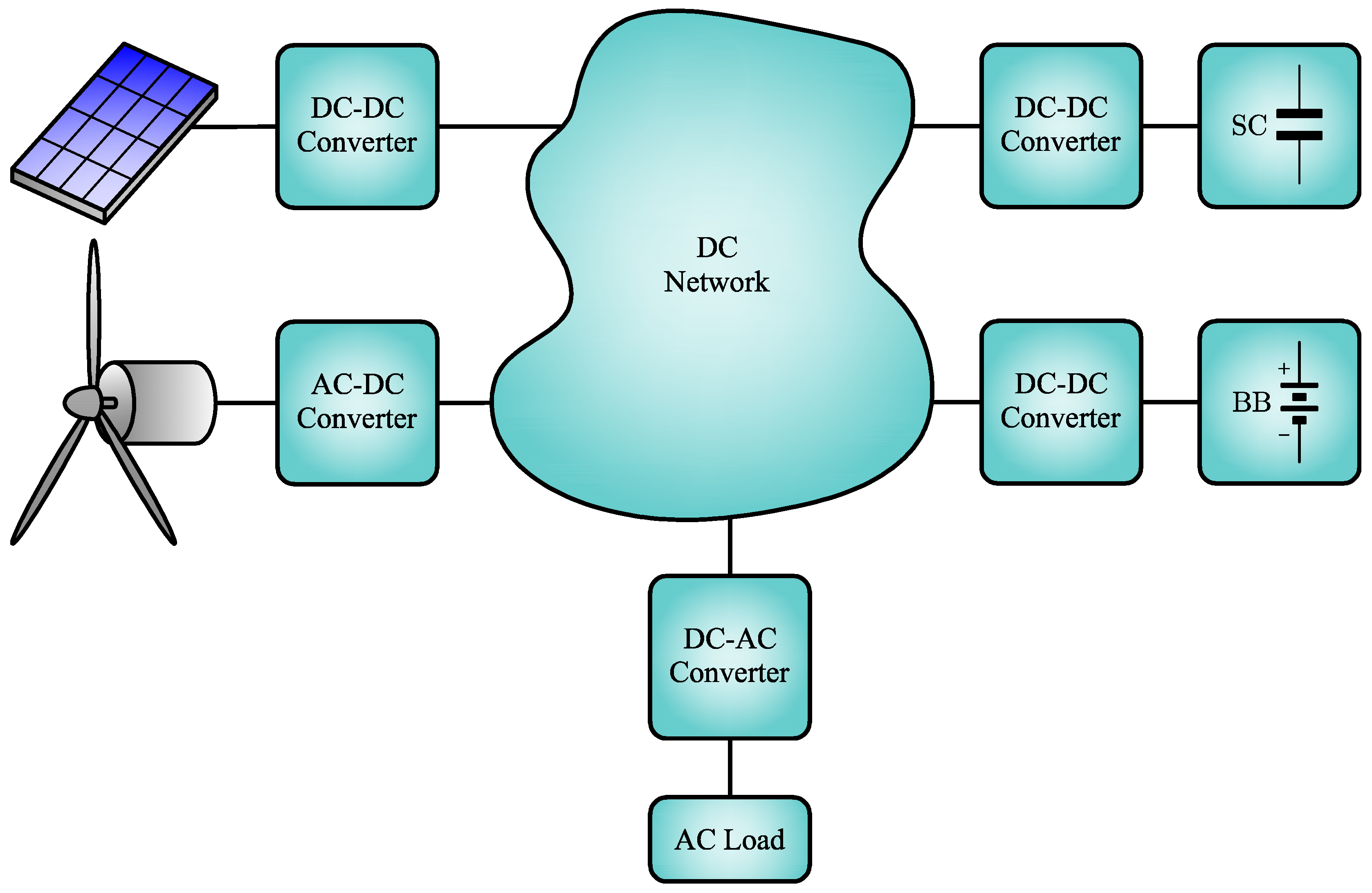
1.1. General Context
1.2. Motivation
1.3. Brief State-of-the-Art
1.4. Contribution and Scope
- ✓
- A passivity-based control design that is easily implementable with the main advantages of the classical PI controllers that allows tracking a sinusoidal trajectory by transforming this into a regulation problem. The proposed PI-PBC design also allows guaranteeing stability conditions based on the Lyapunov theory by applying the properties of the Hamiltonian energy models.
- ✓
- The proposed controller can maintain objective controls, which are to regulate constant voltage amplitude and constant frequency although the test system feeds a non-linear load, demonstrating the generation of a robust three-phase balanced signal. This is achieved by avoiding the use of classical phase-locked loops embedded in virtual synchronous emulations that emulates inertia properties in converters.
- ✓
- The experimental validation in a laboratory prototype with a realistic model of the system include switching effects, losses, and a detailed transistor model to feed passive loads and nonlinear ones.
1.5. Organization of the Document
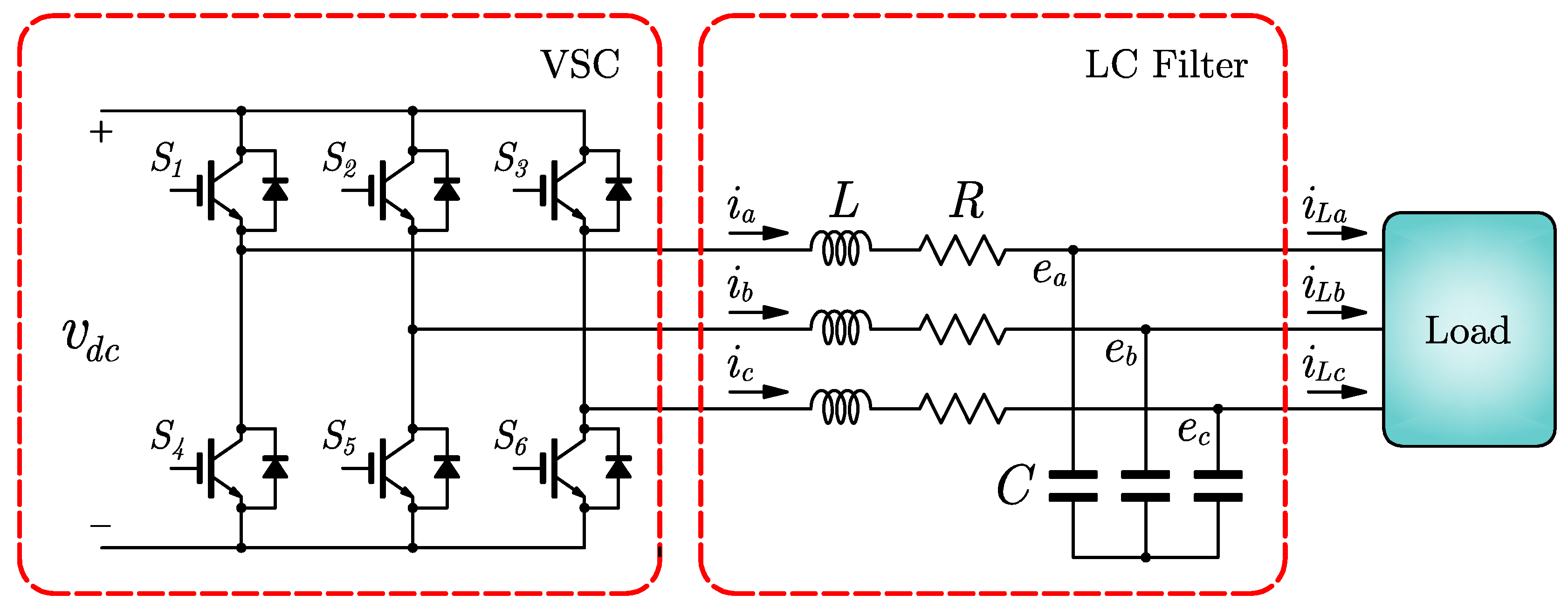
2. System Configuration and Dynamical Model
Dynamical Model
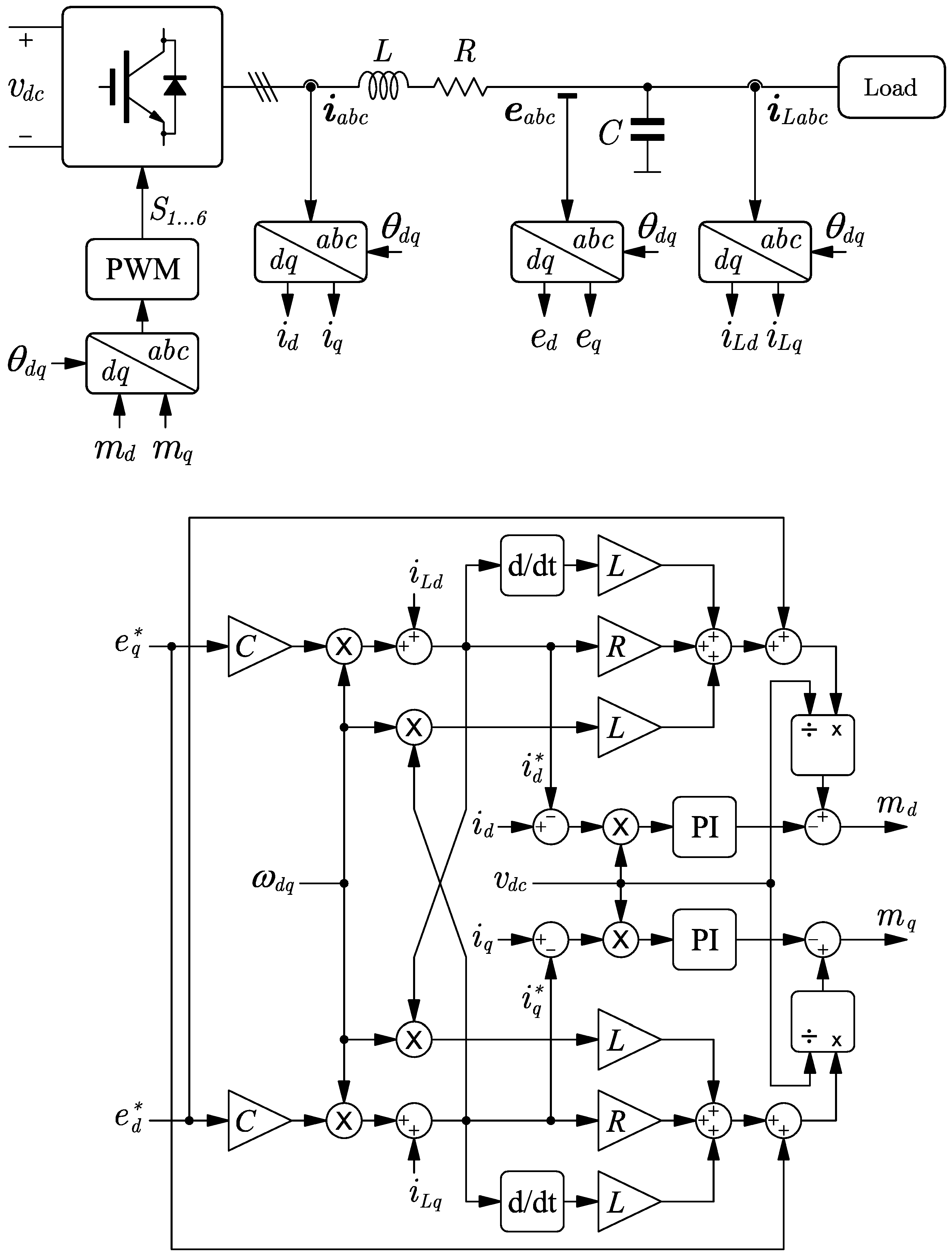
3. PI-PBC Approach
3.1. Control Design
3.2. Control Objective
3.3. Stability Analysis
- ✓
- If there is a Lyapunov candidate function that is positive definite for all , and zero only for , i.e., ,
- ✓
- and the derivative of the Lyapunov function with respect to the time is negative semidefinite, i.e., .
- The PI-PBC design can guarantee stability independently of the value of the parameters of the filter LC since its demonstration is based on the positive definiteness of the matrix in Equation (14) [13]. This matrix is constant and contains at its diagonal the parameters of the filter, which of course are positive in real physical systems. This implies that if there exists variations between the parameters assigned to the controller and the real parameters, it will not compromise the stability of the system in closed-loop [32].
- The control gains assigned to the PI-PBC controller plays an important role in the stability analysis [33]; nevertheless, these need to fulfill an important condition related to the positiveness of their values. Since these are design parameters, we can ensure that they will be positive and the system will remain stable during the closed-loop operation.
- Some unmodeled dynamics such as parasitic resistances in the capacitors connected in parallel to the load or power losses in the converter will help the stable behavior of the system since these parameters introduce additional dampings in the dynamical response of the physical system that we no longer observe in the simulation environment [53].
4. Results
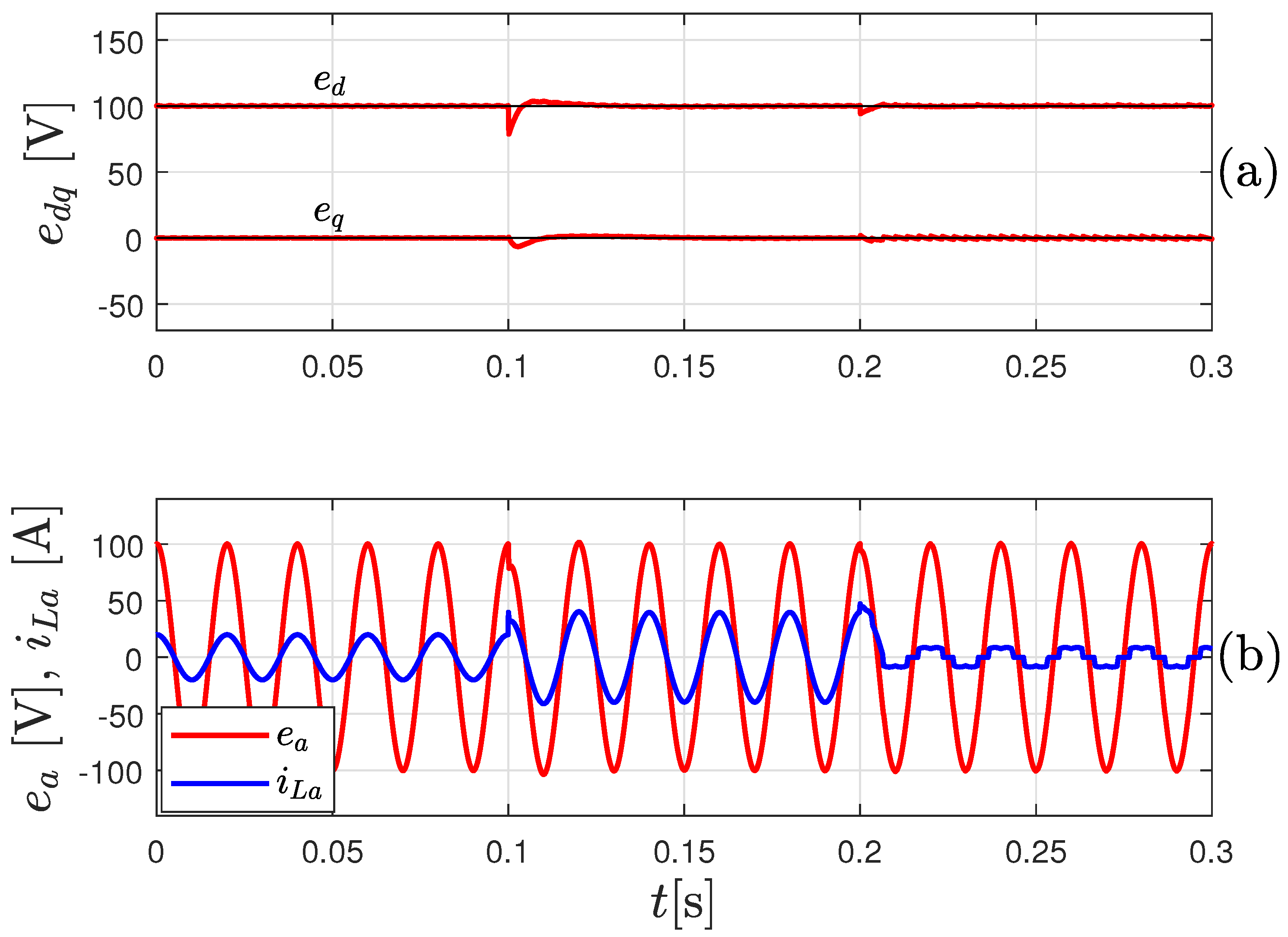
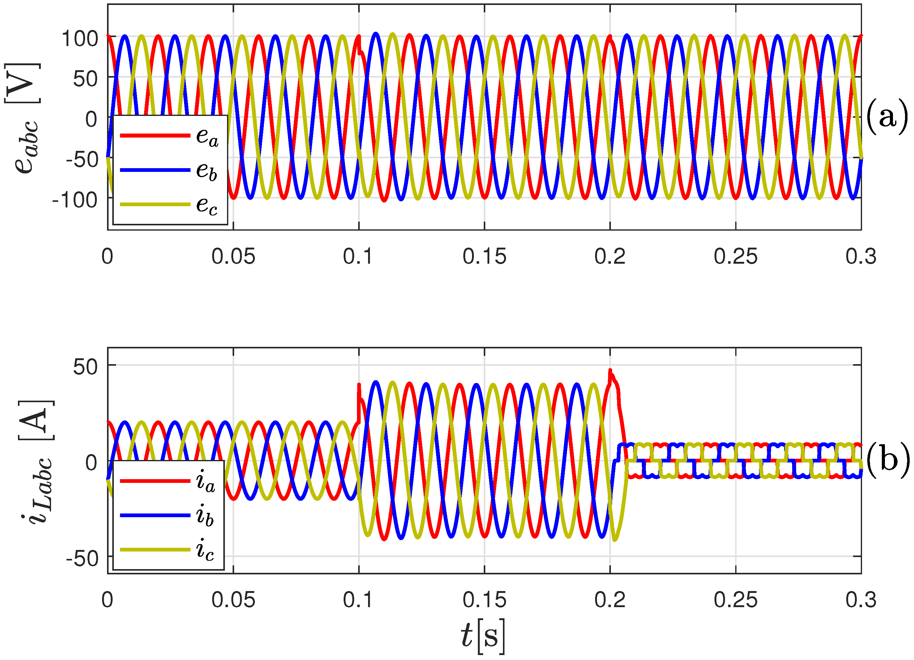
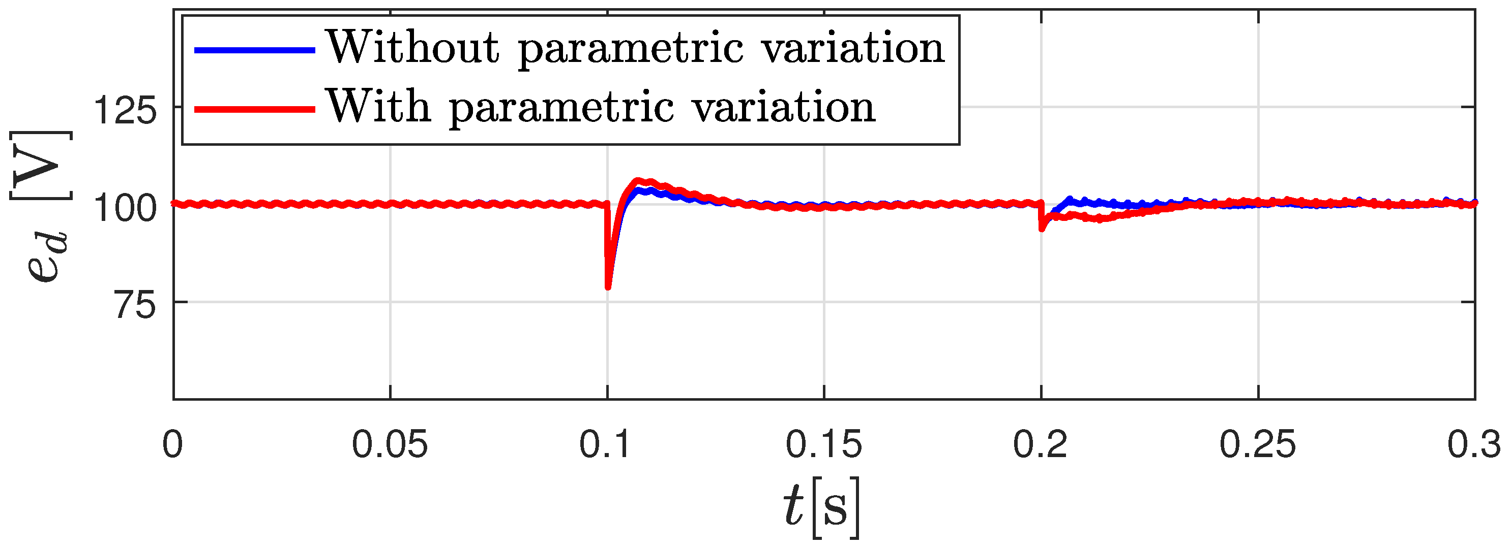
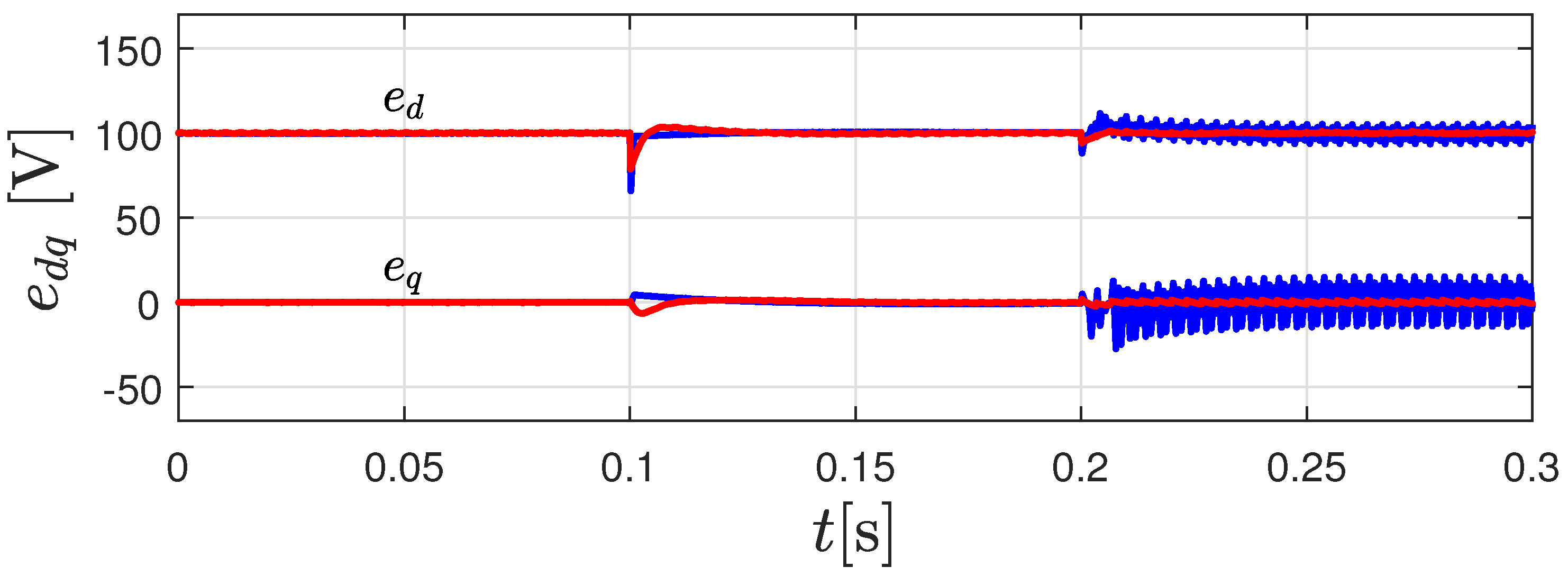
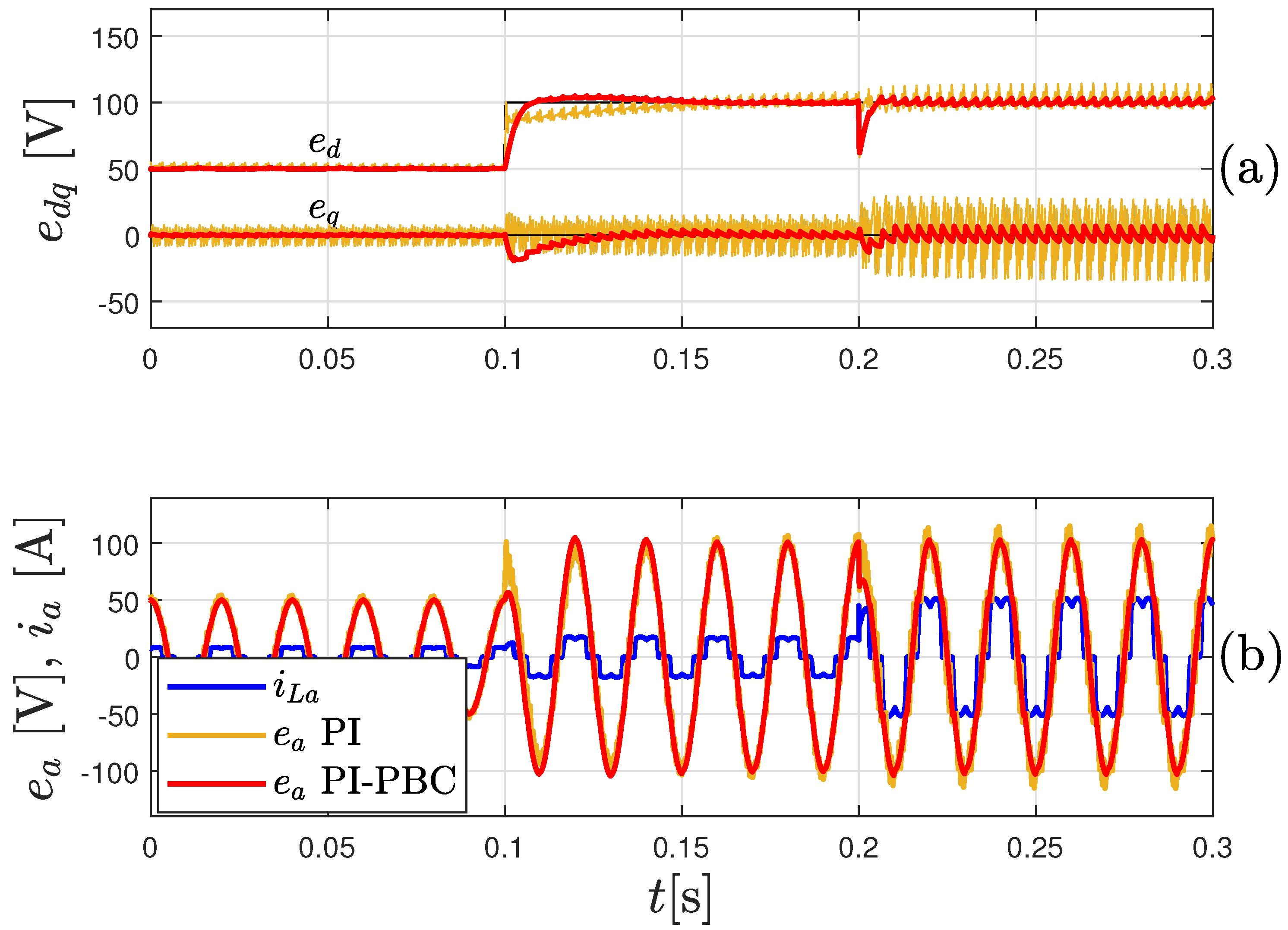
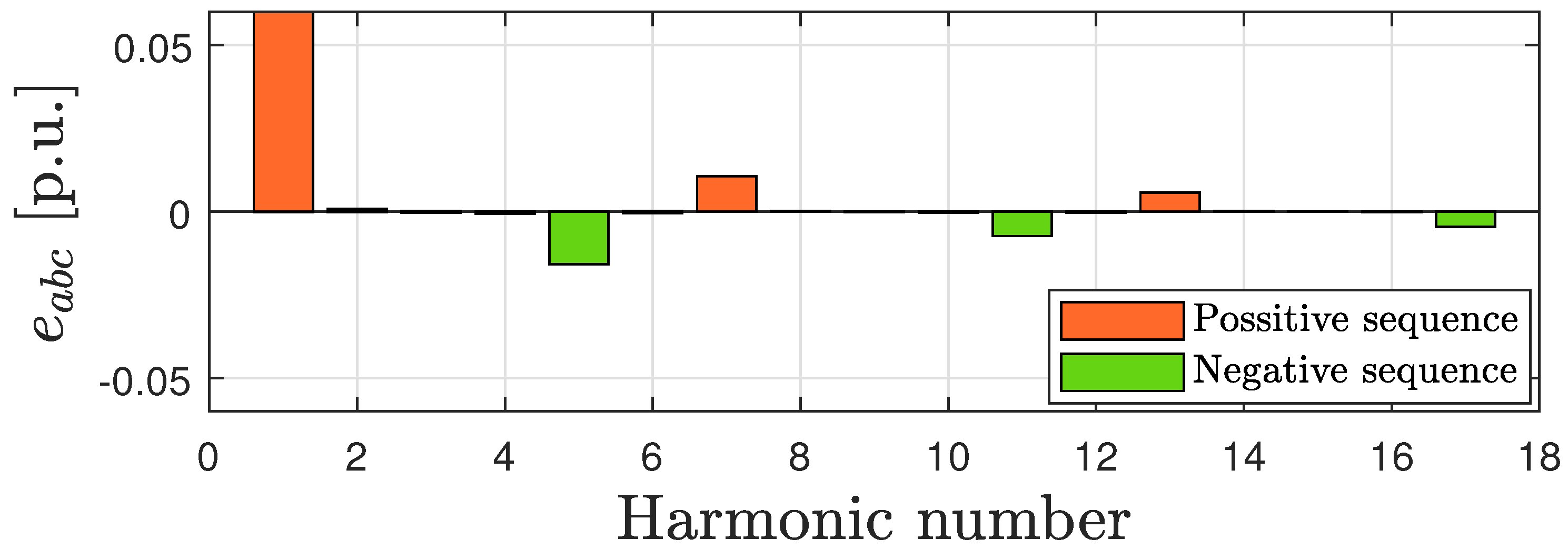
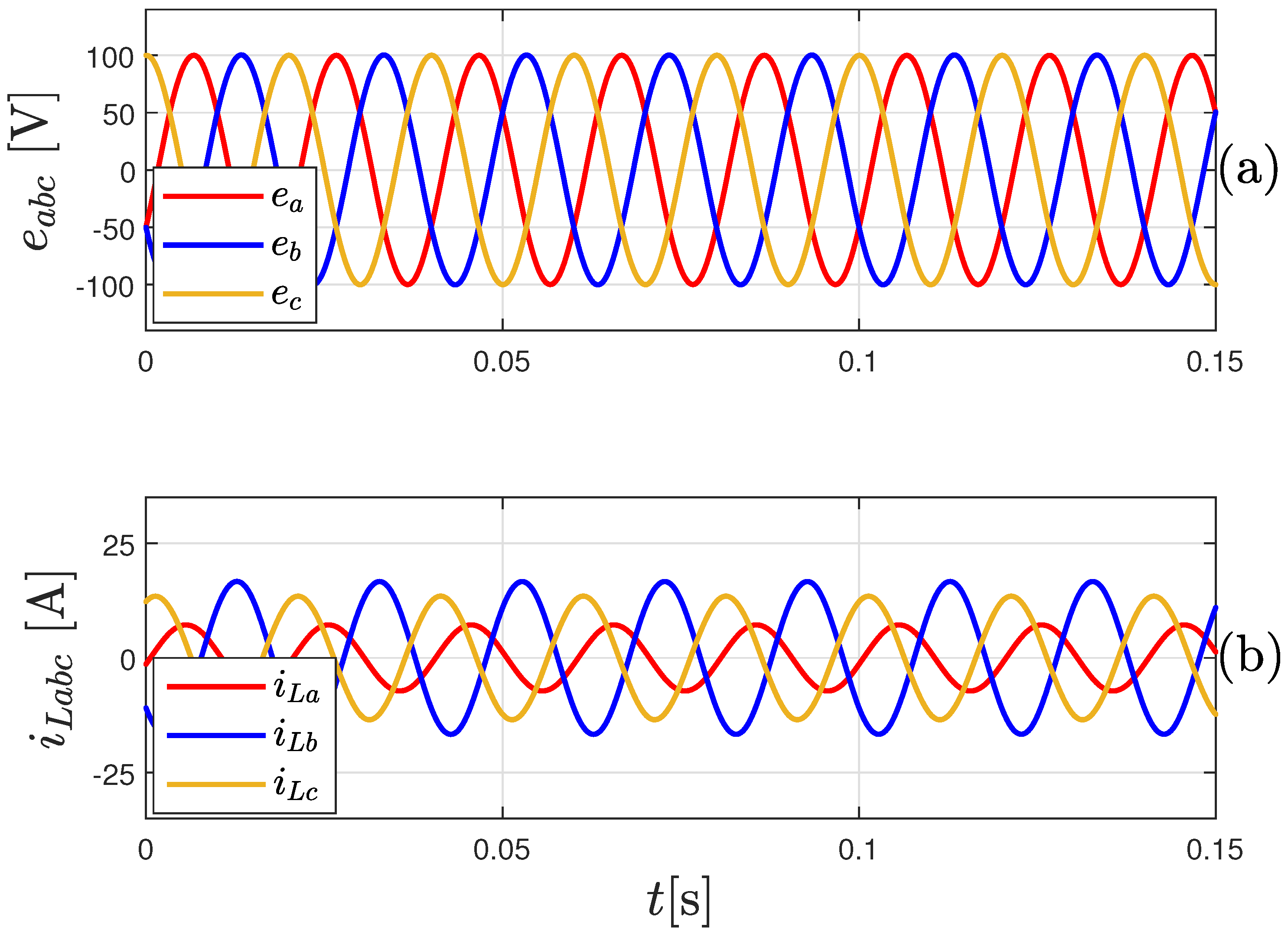
4.1. Simulation Results
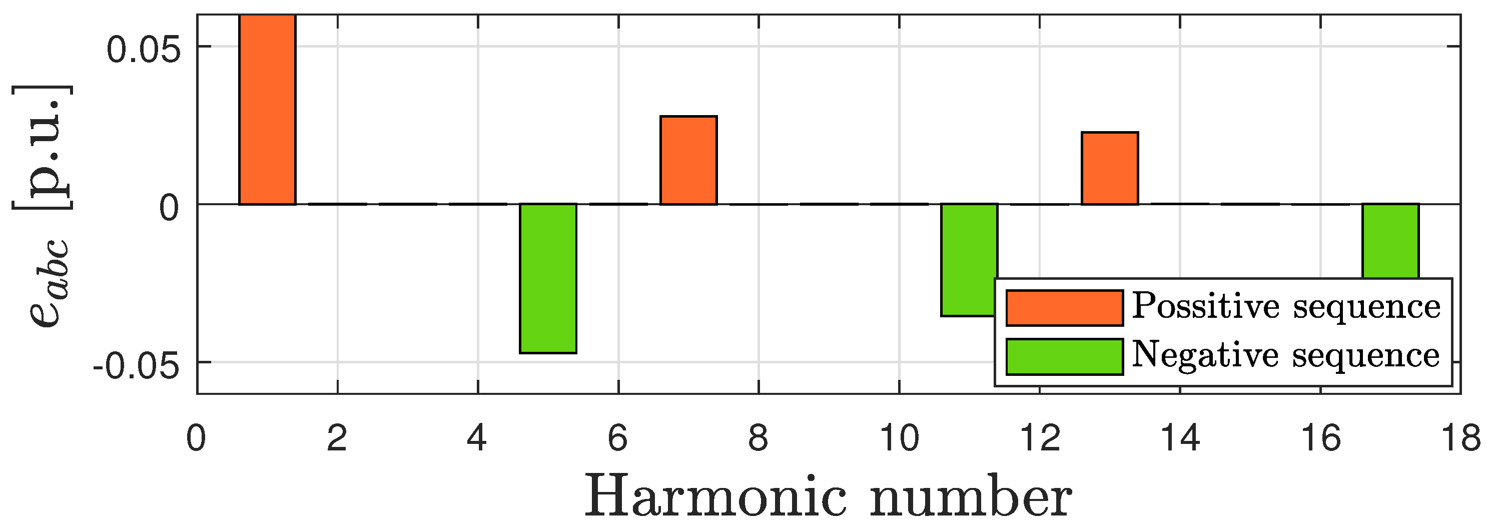
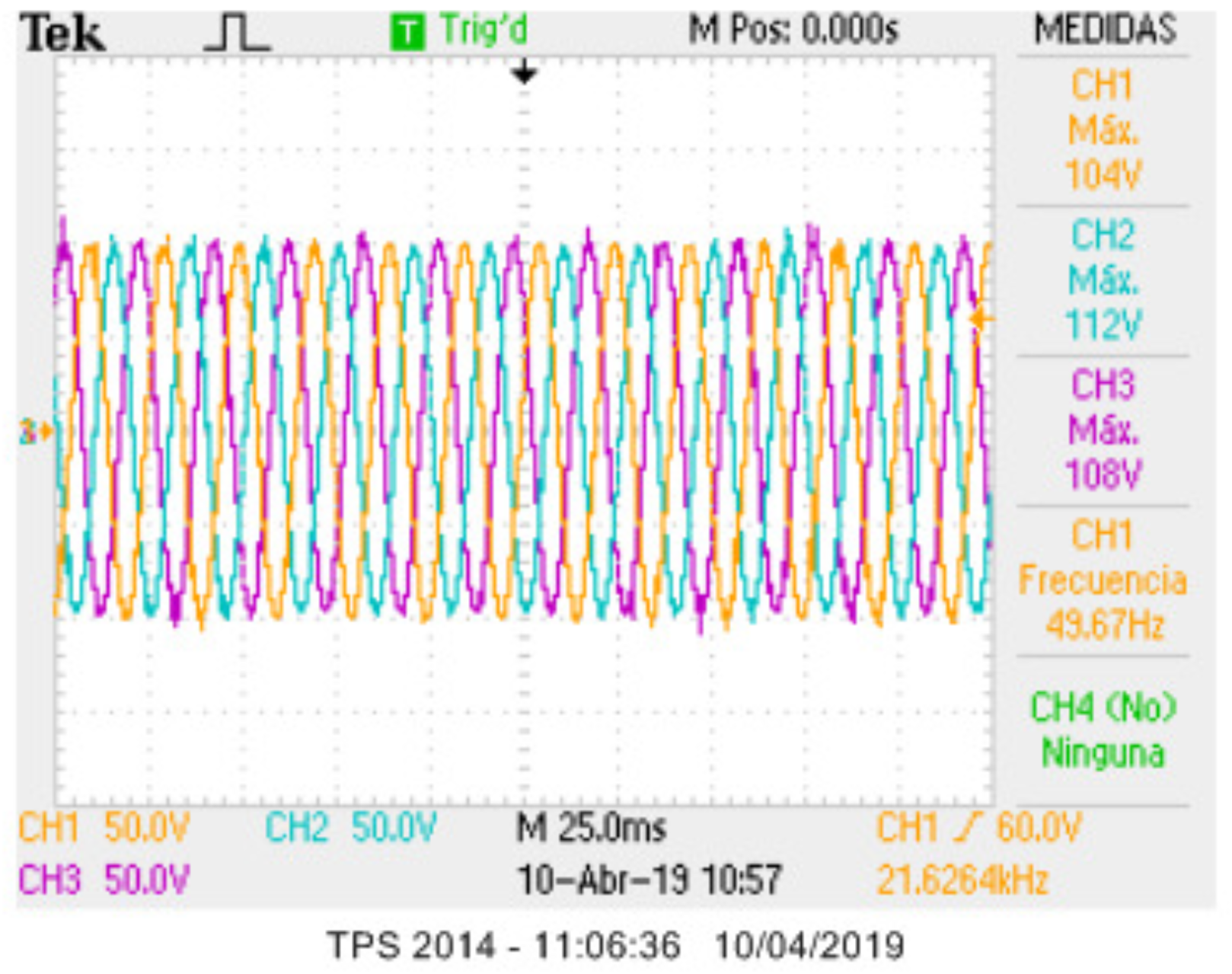
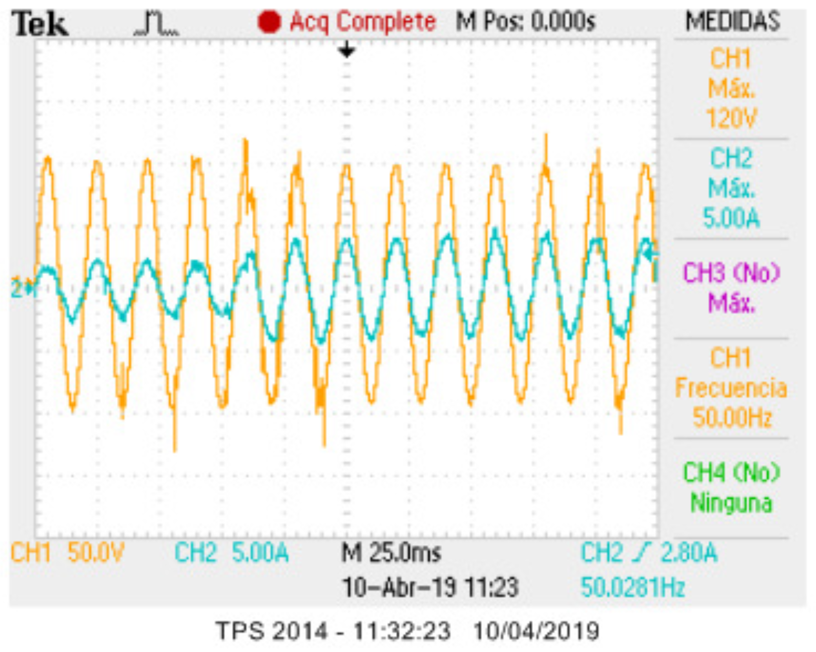
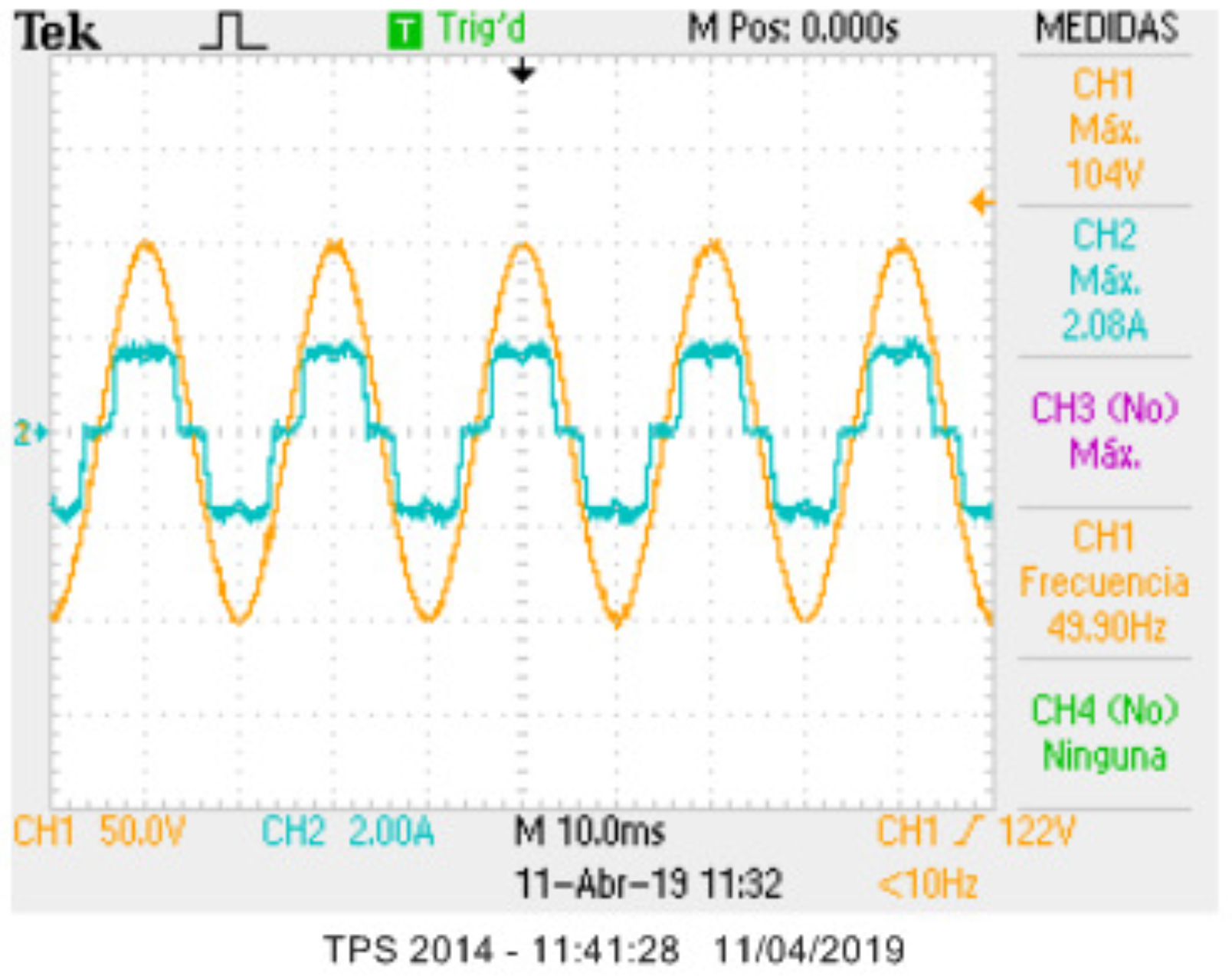
4.2. Experimental Results
5. Conclusions
Author Contributions
Funding
Acknowledgments
Conflicts of Interest
Abbreviations
| Acronyms | |
| AC | Alternating current |
| BB | Battery |
| IDA-PBC | Interconnection and damping assignment passivity-based controller |
| pH | port-Hamiltonian |
| PI-PBC | Proportional-integral passivity-based controller |
| DC | Direct current |
| SC | Supercapacitor |
| RHS | Renewable-based hybrid systems |
| Subscripts and superscripts | |
| * | Admissible trajectory |
| Direct-quadrature reference frame | |
| Parameters | |
| R | Resistance filter |
| L | Inductance filter |
| C | Capacitance filter |
| Variables | |
| Output currents of VSC in the frame | |
| Load currents in the frame | |
| Output voltages of VSC in the frame | |
| modulation indexes in the frame | |
| State vector | |
| State vector with incremental variables | |
| Control input vector | |
| auxiliary variable vector | |
| Inertia matrix | |
| Damping matrix | |
| Interconnection matrix | |
| Input matrix | |
| Energy storage function | |
| Candidate Lyapunov function | |
| Proportional gain matrix | |
| Integral gain matrix | |
References
- Ellabban, O.; Abu-Rub, H.; Blaabjerg, F. Renewable energy resources: Current status, future prospects and their enabling technology. Renew. Sustain. Energy Rev. 2014, 39, 748–764. [Google Scholar] [CrossRef]
- Bueno-Lopez, M.; Lemos, S.G. Electrification in non-interconnected areas: Towards a new vision of rurality in Colombia. IEEE Technol. Soc. Mag. 2017, 36, 73–79. [Google Scholar] [CrossRef]
- Montoya, O.D.; Garcés, A.; Serra, F.M. DERs integration in microgrids using VSCs via proportional feedback linearization control: Supercapacitors and distributed generators. J. Energy Storage 2018, 16, 250–258. [Google Scholar] [CrossRef]
- Zou, P.; Chen, Q.; Xia, Q.; He, G.; Kang, C. Evaluating the Contribution of Energy Storages to Support Large-Scale Renewable Generation in Joint Energy and Ancillary Service Markets. IEEE Trans. Sustain. Energy 2016, 7, 808–818. [Google Scholar] [CrossRef]
- Justo, J.J.; Mwasilu, F.; Lee, J.; Jung, J.W. AC-microgrids versus DC-microgrids with distributed energy resources: A review. Renew. Sustain. Energy Rev. 2013, 24, 387–405. [Google Scholar] [CrossRef]
- Kumar, D.; Zare, F.; Ghosh, A. DC Microgrid Technology: System Architectures, AC Grid Interfaces, Grounding Schemes, Power Quality, Communication Networks, Applications, and Standardizations Aspects. IEEE Access 2017, 5, 12230–12256. [Google Scholar] [CrossRef]
- Gavriluta, C.; Candela, I.; Citro, C.; Luna, A.; Rodriguez, P. Design considerations for primary control in multi-terminal VSC-HVDC grids. Electr. Power Syst. Res. 2015, 122, 33–41. [Google Scholar] [CrossRef]
- Gil-González, W.; Montoya, O.D.; Garces, A. Direct power control for VSC-HVDC systems: An application of the global tracking passivity-based PI approach. Int. J. Electr. Power Energy Syst. 2019, 110, 588–597. [Google Scholar] [CrossRef]
- Ornelas-Tellez, F.; Rico-Melgoza, J.J.; Espinosa-Juarez, E.; Sanchez, E.N. Optimal and Robust Control in DC Microgrids. IEEE Trans. Smart Grid 2018, 9, 5543–5553. [Google Scholar] [CrossRef]
- Roy, T.K.; Mahmud, M.A.; Oo, A.M.T.; Haque, M.E.; Muttaqi, K.M.; Mendis, N. Nonlinear Adaptive Backstepping Controller Design for Islanded DC Microgrids. IEEE Trans. Ind. Appl. 2018, 54, 2857–2873. [Google Scholar] [CrossRef]
- Garces, A. Uniqueness of the power flow solutions in low voltage direct current grids. Electr. Power Syst. Res. 2017, 151, 149–153. [Google Scholar] [CrossRef]
- Opiyo, N.N. A comparison of DC- versus AC-based minigrids for cost-effective electrification of rural developing communities. Energy Rep. 2019, 5, 398–408. [Google Scholar] [CrossRef]
- Serra, F.M.; Angelo, C.H.D. IDA-PBC controller design for grid connected Front End Converters under non-ideal grid conditions. Electr. Power Syst. Res. 2017, 142, 12–19. [Google Scholar] [CrossRef]
- Montoya, O.D.; Gil-González, W.; Serra, F.M. PBC Approach for SMES Devices in Electric Distribution Networks. IEEE Trans. Circuits Syst. II 2018, 65, 2003–2007. [Google Scholar] [CrossRef]
- Han, J.; Liu, Z.; Liang, N.; Song, Q.; Li, P. An Autonomous Power-Frequency Control Strategy Based on Load Virtual Synchronous Generator. Processes 2020, 8, 433. [Google Scholar] [CrossRef]
- Serra, F.M.; Angelo, C.H.D.; Forchetti, D.G. IDA-PBC control of a DC–AC converter for sinusoidal three-phase voltage generation. Int. J. Electron. 2017, 104, 93–110. [Google Scholar] [CrossRef]
- Ye, Y.; Zhou, K.; Zhang, B.; Wang, D.; Wang, J. High-Performance Repetitive Control of PWM DC-AC Converters With Real-Time Phase-Lead FIR Filter. IEEE Trans. Circuits Syst. II 2006, 53, 768–772. [Google Scholar] [CrossRef]
- Khefifi, N.; Houari, A.; Machmoum, M.; Ghanes, M.; Ait-Ahmed, M. Control of grid forming inverter based on robust IDA-PBC for power quality enhancement. Sustain. Energy Grids Netw. 2019, 20, 100276. [Google Scholar] [CrossRef]
- Amin, W.T.; Montoya, O.D.; Garrido, V.M.; Gil-González, W.; Garces, A. Voltage and Frequency Regulation on Isolated AC Three-phase Microgrids via s-DERs. In Proceedings of the 2019 IEEE Green Technologies Conference (GreenTech), Lafayette, LA, USA, 3–6 April 2019; pp. 1–6. [Google Scholar]
- Huang, X.; Wang, K.; Li, G.; Zhang, H. Virtual Inertia-Based Control Strategy of Two-Stage Photovoltaic Inverters for Frequency Support in Islanded Micro-Grid. Electronics 2018, 7, 340. [Google Scholar] [CrossRef]
- Fang, J.; Lin, P.; Li, H.; Yang, Y.; Tang, Y. An Improved Virtual Inertia Control for Three-Phase Voltage Source Converters Connected to a Weak Grid. IEEE Trans. Power Electron. 2019, 34, 8660–8670. [Google Scholar] [CrossRef]
- Haque, M.E.; Negnevitsky, M.; Muttaqi, K.M. A Novel Control Strategy for a Variable-Speed Wind Turbine With a Permanent-Magnet Synchronous Generator. IEEE Trans. Ind. Appl. 2010, 46, 331–339. [Google Scholar] [CrossRef]
- Kim, D.; Lee, D. Feedback Linearization Control of Three-Phase UPS Inverter Systems. IEEE Trans. Ind. Electron. 2010, 57, 963–968. [Google Scholar] [CrossRef]
- Loh, P.C.; Newman, M.J.; Zmood, D.N.; Holmes, D.G. A comparative analysis of multiloop voltage regulation strategies for single and three-phase UPS systems. IEEE Trans. Power Electron. 2003, 18, 1176–1185. [Google Scholar] [CrossRef]
- Mattavelli, P. Synchronous-frame harmonic control for high-performance AC power supplies. IEEE Trans. Ind. Appl. 2001, 37, 864–872. [Google Scholar] [CrossRef]
- Lidozzi, A.; Calzo, G.L.; Solero, L.; Crescimbini, F. Integral-resonant control for stand-alone voltage source inverters. IET Power Electron. 2013, 7, 271–278. [Google Scholar] [CrossRef]
- Mohamed, I.S.; Zaid, S.A.; Elsayed, H.M.; Abu-Elyazeed, M. Three-phase inverter with output LC filter using predictive control for UPS applications. In Proceedings of the 2013 International Conference on Control, Decision and Information Technologies (CoDIT), Hammamet, Tunisia, 6–8 May 2013; IEEE: Piscataway, NJ, USA, 2013; pp. 489–494. [Google Scholar]
- Talbi, B.; Krim, F.; Laib, A.; Sahli, A. Model predictive voltage control of a single-phase inverter with output LC filter for stand-alone renewable energy systems. Electr. Eng. 2020. [Google Scholar] [CrossRef]
- Valderrama, G.E.; Stankovic, A.M.; Mattavelli, P. Dissipativity-based adaptive and robust control of UPS in unbalanced operation. IEEE Trans. Power Electron. 2003, 18, 1056–1062. [Google Scholar] [CrossRef]
- Ortega, R.; van der Schaft, A.; Maschke, B.; Escobar, G. Interconnection and damping assignment passivity-based control of port-controlled Hamiltonian systems. Automatica 2002, 38, 585–596. [Google Scholar] [CrossRef]
- Perez, M.; Ortega, R.; Espinoza, J.R. Passivity-based PI control of switched power converters. IEEE Trans. Control Syst. Technol. 2004, 12, 881–890. [Google Scholar] [CrossRef]
- Cisneros, R.; Pirro, M.; Bergna, G.; Ortega, R.; Ippoliti, G.; Molinas, M. Global tracking passivity-based PI control of bilinear systems: Application to the interleaved boost and modular multilevel converters. Control Eng. Pract. 2015, 43, 109–119. [Google Scholar] [CrossRef]
- Gil-González, W.; Montoya, O.D.; Garces, A. Control of a SMES for mitigating subsynchronous oscillations in power systems: A PBC-PI approach. J. Energy Storage 2018, 20, 163–172. [Google Scholar] [CrossRef]
- Cisneros, R.; Mancilla-David, F.; Ortega, R. Passivity-Based Control of a Grid-Connected Small-Scale Windmill With Limited Control Authority. IEEE J. Emerg. Sel. Top. Power Electron. 2013, 1, 247–259. [Google Scholar] [CrossRef]
- Montoya, O.D.; Gil-González, W.; Garces, A. Distributed energy resources integration in single-phase microgrids: An application of IDA-PBC and PI-PBC approaches. Int. J. Electr. Power Energy Syst. 2019, 112, 221–231. [Google Scholar] [CrossRef]
- Montoya, O.D.; Gil-González, W.; Avila-Becerril, S.; Garces, A.; Espinosa-Pérez, G. Integración de REDs en Redes AC: Una Familia de Controladores Basados en Pasividad. Revista Iberoamericana De Automática E Informática Industrial 2019, 16, 212. [Google Scholar] [CrossRef]
- Montoya, O.D.; Garces, A.; Avila-Becerril, S.; Espinosa-Pérez, G.; Serra, F.M. Stability Analysis of Single-Phase Low-Voltage AC Microgrids With Constant Power Terminals. IEEE Trans. Circuits Syst. II Express Briefs 2019, 66, 1212–1216. [Google Scholar] [CrossRef]
- Luyben, W.L. Tuning Proportional-Integral-Derivative Controllers for Integrator/Deadtime Processes. Ind. Eng. Chem. Res. 1996, 35, 3480–3483. [Google Scholar] [CrossRef]
- Ruz, M.; Garrido, J.; Vazquez, F.; Morilla, F. Interactive Tuning Tool of Proportional-Integral Controllers for First Order Plus Time Delay Processes. Symmetry 2018, 10, 569. [Google Scholar] [CrossRef]
- Ahamad, A.; Yadav, C.; Ahuja, S.; Nema, S.; Padhy, P.K. PID tuning procedure based on simplified single parameter optimization. In Proceedings of the 2013 International Conference on Control, Automation, Robotics and Embedded Systems (CARE), Jabalpur, India, 16–18 December 2013; pp. 1–5. [Google Scholar]
- Sanchis, R.; Romero, J.A.; Balaguer, P. Tuning of PID controllers based on simplified single parameter optimisation. Int. J. Control 2010, 83, 1785–1798. [Google Scholar] [CrossRef]
- Irshad, M.; Ali, A. Optimal tuning rules for PI/PID controllers for inverse response processes. IFAC-PapersOnLine 2018, 51, 413–418. [Google Scholar] [CrossRef]
- Pradhan, R.; Majhi, S.K.; Pradhan, J.K.; Pati, B.B. Antlion optimizer tuned PID controller based on Bode ideal transfer function for automobile cruise control system. J. Ind. Inf. Integr. 2018, 9, 45–52. [Google Scholar] [CrossRef]
- Meena, D.C.; Devanshu, A. Genetic algorithm tuned PID controller for process control. In Proceedings of the 2017 International Conference on Inventive Systems and Control (ICISC), Coimbatore, India, 19–20 January 2017; pp. 1–6. [Google Scholar]
- Barisal, A. Comparative performance analysis of teaching learning based optimization for automatic load frequency control of multi-source power systems. Int. J. Electr. Power Energy Syst. 2015, 66, 67–77. [Google Scholar] [CrossRef]
- Ab. Talib, M.H.; Mat Darns, I.Z. Self-tuning PID controller for active suspension system with hydraulic actuator. In Proceedings of the 2013 IEEE Symposium on Computers Informatics (ISCI), Langkawi, Malaysia, 7–9 April 2013; pp. 86–91. [Google Scholar]
- Tejado, I.; Vinagre, B.; Traver, J.; Prieto-Arranz, J.; Nuevo-Gallardo, C. Back to Basics: Meaning of the Parameters of Fractional Order PID Controllers. Mathematics 2019, 7, 530. [Google Scholar] [CrossRef]
- Komurcugil, H. Steady-State Analysis and Passivity-Based Control of Single-Phase PWM Current-Source Inverters. IEEE Trans. Ind. Electron. 2010, 57, 1026–1030. [Google Scholar] [CrossRef]
- He, J.; Li, Y.W. Generalized Closed-Loop Control Schemes with Embedded Virtual Impedances for Voltage Source Converters with LC or LCL Filters. IEEE Trans. Power Electron. 2012, 27, 1850–1861. [Google Scholar] [CrossRef]
- Peña-Asensio, A.; Arnaltes-Gómez, S.; Rodriguez-Amenedo, J.L.; García-Plaza, M.; Carrasco, J.E.G.; de las Morenas, J.M.A.M. A Voltage and Frequency Control Strategy for Stand-Alone Full Converter Wind Energy Conversion Systems. Energies 2018, 11, 474. [Google Scholar] [CrossRef]
- Sivadas, D.; Vasudevan, K. Stability Analysis of Three-Loop Control for Three-Phase Voltage Source Inverter Interfaced to the Grid Based on State Variable Estimation. IEEE Trans. Ind. Appl. 2018, 54, 6508–6518. [Google Scholar] [CrossRef]
- Gil-González, W.; Serra, F.M.; Montoya, O.D.; Ramírez, C.A.; Orozco-Henao, C. Direct Power Compensation in AC Distribution Networks with SCES Systems via PI-PBC Approach. Symmetry 2020, 12, 666. [Google Scholar] [CrossRef]
- Zahid, Z.U.; Lai, J.J.; Huang, X.K.; Madiwale, S.; Hou, J. Damping impact on dynamic analysis of LLC resonant converter. In Proceedings of the 2014 IEEE Applied Power Electronics Conference and Exposition—APEC 2014, Fort Worth, TX, USA, 16–20 March 2014; pp. 2834–2841. [Google Scholar]
- Serra, F.M.; Angelo, C.H.D.; Forchetti, D.G. Interconnection and damping assignment control of a three-phase front end converter. Int. J. Electr. Power Energy Syst. 2014, 60, 317–324. [Google Scholar] [CrossRef]


| Parameter | Value | Unit | Parameter | Value | Unit |
|---|---|---|---|---|---|
| Inductance (L) | 1.25 | mH | Switching frequency () | 20 | kHz |
| Resistance (R) | 0.2 | Output frequency (f) | 50 | Hz | |
| Capacitance (C) | 45 | F | DC-link voltage () | 311 | V |
| Internal IGBT resistance () | 10 | m | DC-link capacitance () | 5400 | F |
© 2020 by the authors. Licensee MDPI, Basel, Switzerland. This article is an open access article distributed under the terms and conditions of the Creative Commons Attribution (CC BY) license (http://creativecommons.org/licenses/by/4.0/).
Share and Cite
Serra, F.M.; Fernández, L.M.; Montoya, O.D.; Gil-González, W.; Hernández, J.C. Nonlinear Voltage Control for Three-Phase DC-AC Converters in Hybrid Systems: An Application of the PI-PBC Method. Electronics 2020, 9, 847. https://doi.org/10.3390/electronics9050847
Serra FM, Fernández LM, Montoya OD, Gil-González W, Hernández JC. Nonlinear Voltage Control for Three-Phase DC-AC Converters in Hybrid Systems: An Application of the PI-PBC Method. Electronics. 2020; 9(5):847. https://doi.org/10.3390/electronics9050847
Chicago/Turabian StyleSerra, Federico M., Lucas M. Fernández, Oscar D. Montoya, Walter Gil-González, and Jesus C. Hernández. 2020. "Nonlinear Voltage Control for Three-Phase DC-AC Converters in Hybrid Systems: An Application of the PI-PBC Method" Electronics 9, no. 5: 847. https://doi.org/10.3390/electronics9050847
APA StyleSerra, F. M., Fernández, L. M., Montoya, O. D., Gil-González, W., & Hernández, J. C. (2020). Nonlinear Voltage Control for Three-Phase DC-AC Converters in Hybrid Systems: An Application of the PI-PBC Method. Electronics, 9(5), 847. https://doi.org/10.3390/electronics9050847