Review

Foreign Object Detection for Electric Vehicle Wireless Charging

1
State Key Laboratory of Automotive Simulation and Control, Jilin University, Jilin 130025, China
2
Department of Electrical Engineering, Kunming University of Science and Technology, Kunming 650500, China
3
Department of Electrical Engineering, University of Cadiz, EPS Algeciras, Avda. Ramón Puyol, s/n 11202 Algeciras, Cadiz, Spain
*
Authors to whom correspondence should be addressed.
Electronics 2020, 9(5), 805; https://doi.org/10.3390/electronics9050805
Submission received: 29 March 2020 / Revised: 4 May 2020 / Accepted: 8 May 2020 / Published: 14 May 2020
(This article belongs to the Special Issue Emerging Technologies for Wireless Power Transfer in Transportation)

Abstract

:
Wireless power transfer technology is being widely used in electric vehicle wireless-charging applications, and foreign object detection (FOD) is an important module that is needed to satisfy the transmission and safety requirements. FOD mostly includes two key parts: metal object detection (MOD) and living object detection (LOD), which should be implemented during the charging process. In this paper, equivalent circuit models of a metal object and a living object are proposed, and the FOD methods are reviewed and analyzed within a unified framework based on the proposed FOD models. A comparison of these detection methods and future challenges is also discussed. Based on these analyses, detection methods that employ an additional circuit for detection are recommended for FOD in electric vehicle wireless-charging applications.

1. Introduction

Electric vehicles (EV) are expected to be a promising alternative to vehicles powered by fossil fuels and to reduce emissions from the transportation sector. However, short driving ranges and long charging times substantially hinder consumers from selecting EVs. Currently, EV charging is mainly based on conductive charging, in which plugs and cables affect the user’s charging experience. Additionally, potential risks exist, such as electric shock due to bad weather and damaged or stolen plugs and cables. Battery swapping is fast and convenient, but the large investment required for battery packs and the standardization problem are obstacles to the large-scale promotion of this technology. With the successful demonstration of 60 W power transmission over a distance of 2 m from the Massachusetts Institute of Technology (MIT) in 2007 [1], wireless charging is being widely studied in the automotive industry. Since charging plugs and cables are eliminated, wireless charging is safe, convenient, and reliable [2]. In recent years, wireless-charging products for EVs have been released by companies such as Qualcomm Halo, Plugless Power, OLEV, Bombardier Primove, WiTricity, Momentum Dynamics and Conductix-Wampfler [3,4].
Modern inductive wireless power transfer (WPT) still uses the principle of conventional transformers, but because the primary coil and secondary coil are loosely coupled (the coupling coefficient is usually in the range of 0.1–0.3 [5]), additional magnetic resonant coupling circuits are needed to improve the transfer power and efficiency. The resonant coupling circuit could be a four-coil system with a symmetric or asymmetric structure [1,6,7] or a three-coil system [8,9]. To achieve circuit resonance, compensation circuits are needed. A series-series (SS) circuit is a typical compensation circuit topology [10], which can improve the active power transfer capability. In recent years, inductance-capacitance-capacitance (LCC) compensation circuits have been proposed for automotive applications. With more freedom in the parameter design than in SS circuits, zero-phase-angle, zero-voltage switching and constant voltage/current outputs can be realized by an appropriate parameter design [11,12,13]. Extensive studies of WPT systems have focused on efficiency optimization, including system parameter design [14,15], coil structure design [16,17,18], power electronics design [19], closed-loop control [20], and center frequency selection [21]. Another active area of WPT system research aims to improve the system tolerance to coil misalignments, where a coil misalignment could have a significant influence on the power transfer efficiency [22]. A tuning method [23], a coil array [24] and a mechanical method [25] have been proposed to reduce the impact of misalignment. Just like the magnetic field that is used in inductive power-transfer systems, an electric field can also be used for WPT, which is called capacitive power transfer. Capacitive power transfer does not require ferrites, has better tolerance to misalignment and eliminates the need for high-voltage capacitors [26]. However, the coupling capacitance is usually very small and, therefore, the system requires much higher operating frequencies [27]. To fully use the inductive and capacitive components, a combined inductive and capacitive WPT system was also proposed in [5], and the system performance in the case of a misalignment was improved. In-motion charging, which is also called dynamic charging, is another active area in WPT research. Because an EV is powered directly from the road while driving with in-motion charging, the on-board energy storage system of the EV can be reduced, and therefore, the initial purchase cost will be reduced, and the overall energy and economic performance during operation will be further improved [28,29,30,31,32]. The results in [33] showed that up to 99.3% of drive cycles can be satisfied by having an on-board battery with a 25 mile range and utilizing 50 kW in-motion charging. There are mainly two major kinds of primary magnetic couplers used in inductive dynamic charging: long track couplers and pad arrays. A long track coupler uses a primary cable along an entire portion of a route, and a pad array sequentially energizes track segments [34]. The receiving coil of the long track coupler covers only a small portion of the track, which results in a high leakage electromagnetic field (EMF). The pad array approach significantly reduces the leakage EMF. However, the segment switching circuit is complex and costly and causes output power fluctuations. Reference [35] proposed a multiparalleled LCC reactive power compensation network structure to realize automatic power distribution in segments by a sole inverter, and by optimizing the receiver size, the output power pulsation was reduced in [36].
One of the most limiting factors of EV wireless charging is safety problems, and EMF exposure is a major concern. EMF exposure needs to be rigorously analyzed to ensure that is within acceptable levels [37]. Standards for human exposure to EMFs were specified. The guidelines published by the International Commission on Non-Ionizing Radiation Protection (ICNIRP) [38] and Institute of Electrical and Electronics Engineers (IEEE) Std. C95.1-2005 [39] presented by the IEEE International Committee on Electromagnetic Safety are the most referenced standards. There are also standards specified for WPT: Society of Automotive Engineers (SAE) J2954 [40] and International Electrotechnical Commission (IEC) 61,980 [41], which were published by the SAE in 2016 and the IEC in 2015, respectively. The ICNIRP standard limitation levels were adopted in SAE J2954. These EMF regulations are widely discussed, and corresponding tests have been reported [42,43]. It has been shown that the leakage EMF may exceed human safety constraints without a properly designed shielding system [44], and shielding is necessary to control the EMF for a WPT system in high-power applications [30]. Further studies analyzed the internal electric field induced in tissues of the human body, which was investigated in anatomically based human models [45]. To reduce the leakage EMF, ferrite was used to optimize the magnetic path, and the pulse width of an inverter was adjusted to reduce the harmonics of the EMF [46]. A multimodular WPT system with opposite phase adjacent modules was introduced to cancel the leakage electromagnetic emissions in both an inductive WPT system [47] and a capacitive WPT system [48]. In these structures, the radiated electromagnetic emissions were canceled from each channel.
A further concern regarding the safety of EMF exposure is foreign object detection (FOD). Generally, FOD includes metal object detection (MOD) and living object detection (LOD) [49,50]. The insertion of a metal object in a WPT system can induce an eddy current in the object, which may change the power transmission efficiency or further cause a fire [37,51]. On the other hand, living objects such as cats, dogs or humans may move or even remain close to the transmitting coil of the WPT system, which may also cause serious safety problems. The corresponding standards, such as SAE J2954, require sensors to protect against hazardous FOD conditions. In SAE J2954, both MOD and LOD are required. For non-living objects (metal objects), 13 sample objects with different configurations and sizes are identified in testing, including ignition tests and temperature increase tests. For living objects, a product is validated to be suitable in two phases. The first phase measures the system shutdown from the point of detection of a living object and the subsequent decay time of the magnetic field after the detection sensor has been triggered, and the second phase verifies the suitable detection of living objects moving into the space [40]. With the release of corresponding standards and the development of WPT products, the FOD technique has received increasing attention.
There have been several previous reviews of WPT, covering different aspects such as efficiency, power, safety, and economics [4,28,52,53,54], but few reviews have focused on FOD. This paper studies the FOD technique in EV wireless charging by investigating recent research on the detection methods for metal objects and living objects. MOD and LOD methods are always proposed based on the different aspects of the effect of the foreign object. To analyze the detection theory of these methods, equivalent circuit models of a metal object and a living object are proposed in this paper. Based on the proposed models, the FOD methods are reviewed and analyzed within a unified framework. The characteristics of these methods are comparatively studied with respect to cost, space, sensitivity and complexity, and suitable detection methods are introduced in this paper.
The structure of this paper is as follows: in Section 2, a typical WPT system is introduced, and general circuit models of a metal object and a living object in a WPT system are proposed for the analysis and review of FOD methods. The major FOD methods are introduced and analyzed within a unified framework based on the proposed model in Section 3. The advantages and disadvantages of the FOD methods and future challenges of FOD applications are analyzed in Section 4.

2. Foreign Object Models

This section discusses the equivalent circuit model of a foreign object in a WPT system. First, the basic configuration and operating principle of a typical WPT system are provided as the basis for the future review and analysis of FOD methods. Then, general circuit models of a metal object and a living object in a WPT system are proposed and analyzed.

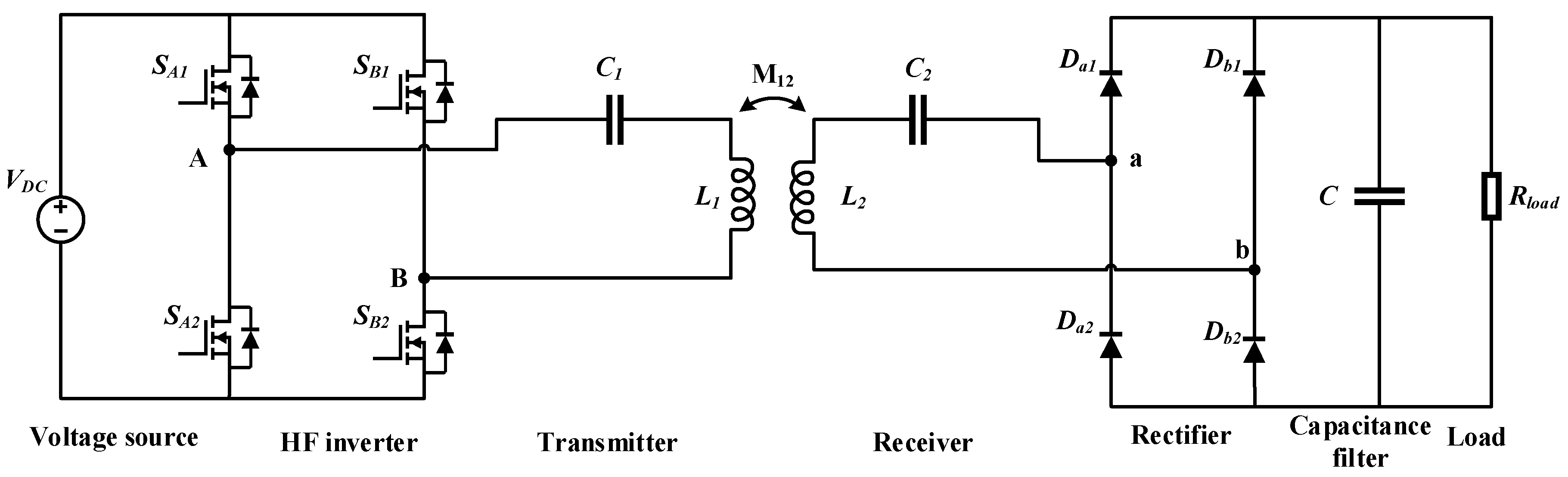
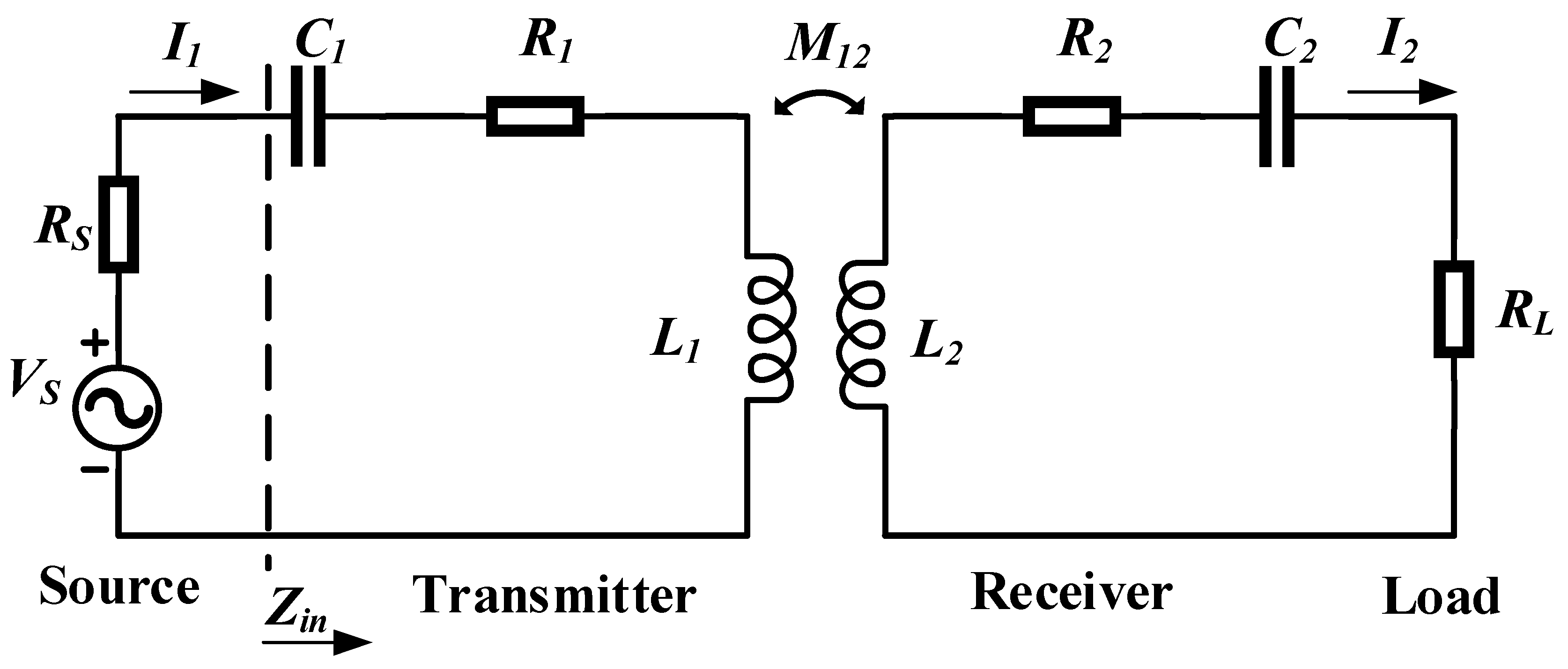
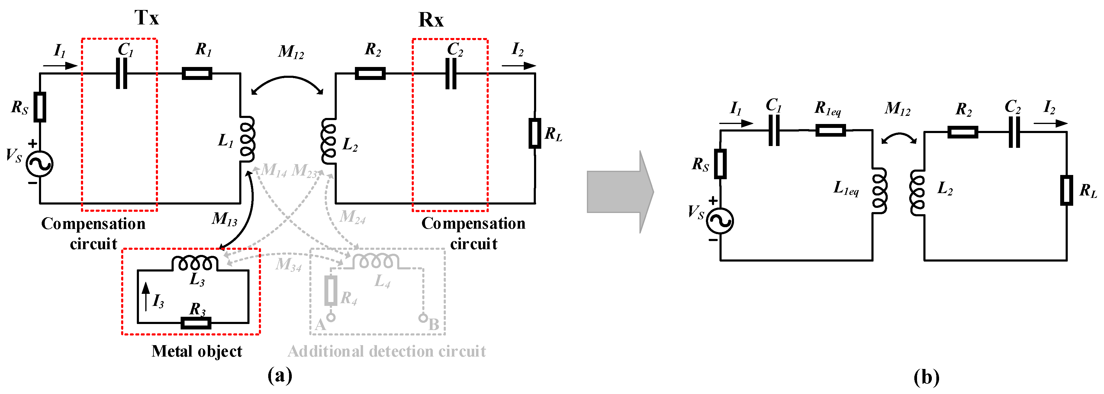
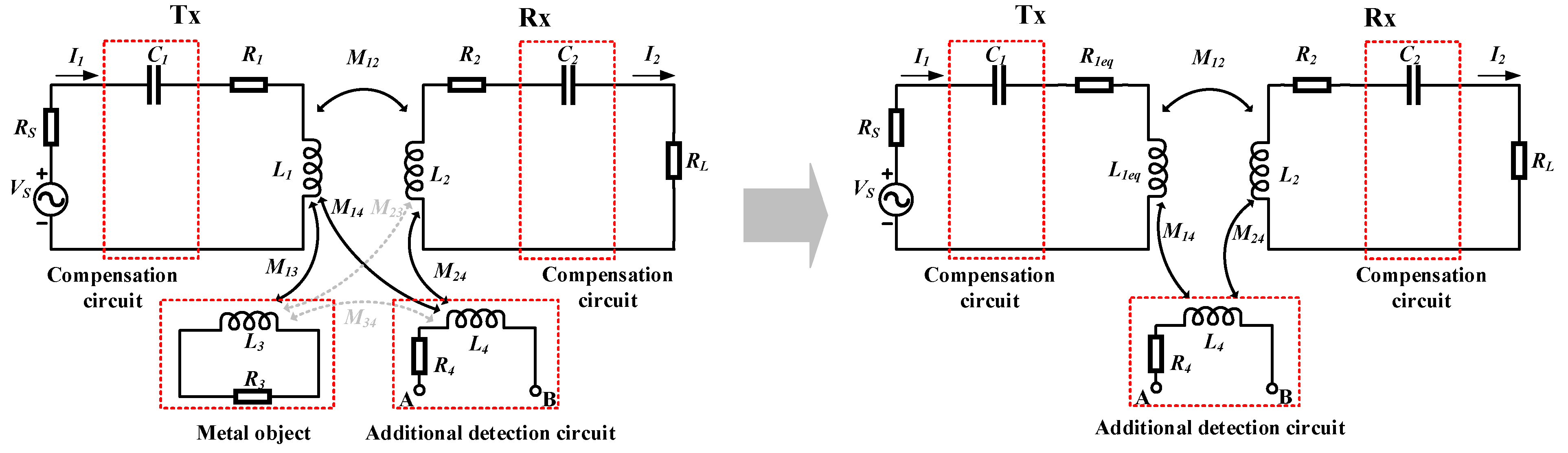
2.1. Typical WPT System

As shown in Figure 1, a typical WPT system always contains two parts: The primary side and the secondary side. The primary side always includes a direct current (DC) voltage source, a high-frequency (HF) inverter, a transmitting coil and its compensation circuit. The secondary side always includes a receiving coil and its compensation circuit, rectifier, filter and load. The compensation circuit can improve the transmission efficiency [1], and there are many structures, such as SS, series-parallel (SP), parallel-series (PS), and parallel-parallel (PP) structures [13]. Without loss of generality, the commonly used resonant SS circuit is used in the following analysis [2,55,56,57], but other topologies can be analyzed in the same way.
Using the fundamental harmonic approximation (FHA) method to analyze the circuit, a simplified equivalent circuit is shown in Figure 2. The square wave voltage provided by the HF inverter is approximated by a fundamental-harmonic pure sinusoidal input voltage source, and the high-order harmonics are neglected. The rectifier and load R l o a d can be seen as an equivalent alternating current (AC) load resistor R L , where R L = R l o a d × 8 / π 2 [53].
In Figure 2, V S , R S , and R L represent the source voltage, internal resistance of the power source and equivalent AC load resistance, respectively; L 1 , L 2 , R 1 and R 2 represent the inductances and resistances of the transmitting and receiving coils, respectively; C 1 and C 2 represent the compensated capacitances of the primary and secondary sides, respectively; M 12 represents the mutual inductance between the transmission coils, and I 1 and I 2 represent the currents flowing through transmitting and receiving coils, respectively.
With the system resonance frequency ω, the circuit equation of Figure 2 can be expressed as:
{ V ˙ S = ( R S + R 1 + j ω L 1 + 1 j ω C 1 ) I ˙ 1 j ω M 12 I ˙ 2 j ω M 12 I ˙ 1 = ( R 2 + R L + j ω L 2 + 1 j ω C 2 ) I ˙ 2
where “·” indicates a phasor when the system operates at the resonance frequency
ω 0 = 1 L 1 C 1 = 1 L 2 C 2
The input impedance of the circuit can be expressed as:
Z i n = R 1 + ω 0 2 M 12 2 R 2 + R L
Therefore, the reflection of the secondary side to the primary side in the resonant case can be seen as a variation of the internal resistance of the transmitting coil.
Q is defined as the quality factor of the circuit or circuit component, which can be expressed as Q = ω L / R . Q 1 , Q 2 and Q C represent the quality factors of the transmitting coil, receiving coil and the system circuit, respectively:
Q 1 = ω 0 L 1 / R 1
Q 2 = ω 0 L 2 / R 2
Q C = ω 0 L 1 / Z i n
The output power to the load and the transmission efficiency at the resonance frequency can be expressed as:
P o u t = ω 0 2 M 12 2 V S 2 R L [ ( R S + R 1 ) ( R 2 + R L ) + ω 0 2 M 12 2 ] 2
η = ω 0 2 M 12 2 R L ( R S + R 1 ) ( R 2 + R L ) 2 + ω 0 2 M 12 2 ( R 2 + R L )
The maximum transmission efficiency of the WPT system can be expressed as [53]:
η max = k 2 Q 1 Q 2 ( 1 + 1 + k 2 Q 1 Q 2 ) 2
where,
k = M 12 / L 1 L 2
As described above, the maximum transmission efficiency is correlated with the coupling coefficient k and the quality factor of the transmission coils, where the coupling coefficient k is related to the mutual inductance and self-inductance and the quality factor is related to the self-inductance, internal resistance and resonance frequency. With changes in the magnetic field coupling structure and energy flow, the coupling effect, resonance frequency and quality factor change correspondingly, leading to a change in the transferred power and transmission efficiency. Therefore, changes that can affect the magnetic field coupling structure and energy flow may affect the transmission performance of the WPT system.

2.2. Foreign Object Models

Foreign objects in a WPT system include metal objects and living objects. A metal object may absorb energy from the EMF and disturb the transmission performance of the WPT system, and a living object exposed to a strong EMF may result in a serious safety problem. To analyze the effect of a foreign object and propose a detection approach, circuit models of the foreign object are needed. In this part, general circuit models of a metal object and a living object based on a typical WPT system are proposed and analyzed within a unified framework.

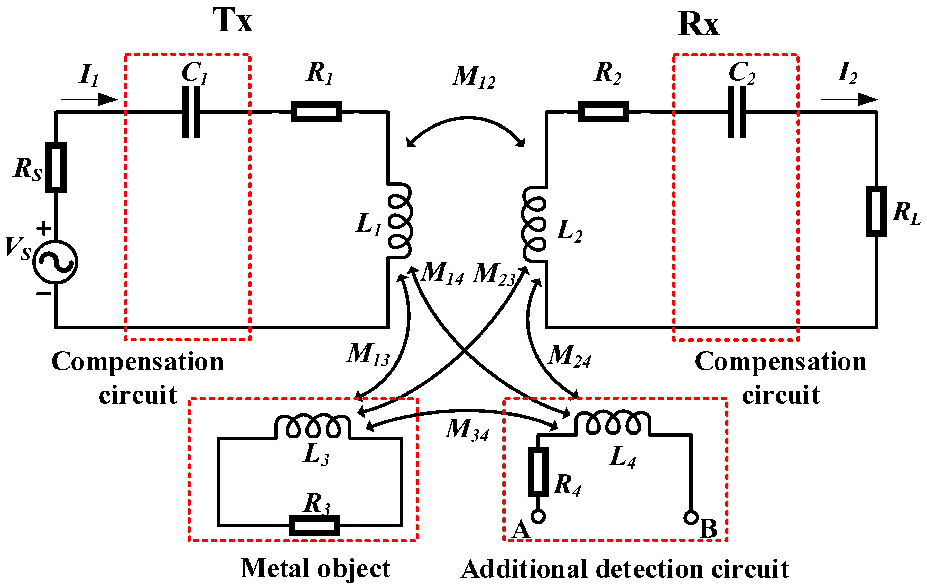
2.2.1. Metal Object Model

The metal object considered here can be any metallic object, even sliced paper with foil, which may have different influences on the WPT system depending on the object. The metal object can be described by a general circuit model, as shown in Figure 3.
This model consists of an original WPT system, a metal object and an additional detection circuit, where the additional detection circuit is optional. The original WPT system is the same as that in the circuit introduced in Section 2. However, the compensation circuit in the transmitter (Tx) and receiver (Rx) can be of different topology. The metal object, which tends to couple with the transmission coils due to the eddy current effect, is modeled as an equivalent LR circuit, where the mutual inductances ( M 13 and M 23 ) and self-inductance ( L 3 ) correspond to the EMF coupled to the metal object, and the resistance ( R 3 ) corresponds to the eddy current losses of the metal object. The capacitance effects of the metal object are always neglected according to references [55,58,59,60]. If an additional detection circuit which always uses the detection coils as the detection equipment exists, a similar EMF coupling effect occurs and the additional detection circuit can be represented by an opened LR circuit. The EMF coupling effect of the detection circuit is represented by L 4 , M 14 , M 24 and M 34 , and the power loss of the detection circuit corresponds to the resistance R 4 . Since the proposed model is only a circuit representation of electromagnetic coupling effects and losses, it is suitable for all metal objects in a WPT system with different coil structures and resonance circuits or different sizes, shapes or positions of metal objects.

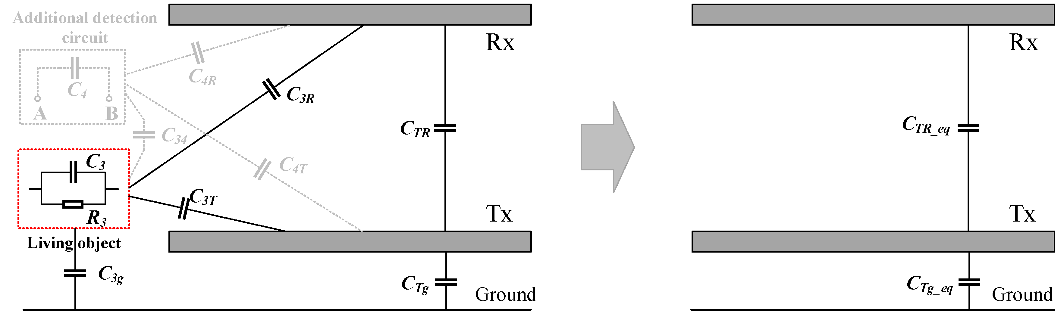
2.2.2. Living Object Model

The living object considered here includes human beings and animals, which always present capacitive characteristics due to the lipid layer in the cellular membrane and the components of the body [61]. When a living object approaches a WPT system, it tends to couple with the transmission pads by capacitive coupling. A general circuit model of the living object is shown in Figure 4.
This model consists of an original WPT system, a living object and an additional optional detection circuit. The original WPT system is demonstrated by the transmission pads, and the transmitting and receiving circuits are not shown in this model. The living object is modeled as a CR circuit, where the mutual capacitances ( C 3 R and C 3 T ) correspond to the electric field coupled to the living object, the mutual capacitance ( C 3 g ) corresponds to the ground effect of the living object, and the internal capacitance ( C 3 ) and resistance ( R 3 ) of the living object are always relatively small and can be neglected according to references [61,62,63,64,65]. If an additional detection circuit exists, a similar electric field coupling effect can be represented by C 34 , C 4 R and C 4 T . The ground effect of the additional detection circuit is neglected in this model due to the location of the detection circuit is always on the surface of Tx pad. Mutual capacitances ( C T R and C T g ) always occur between the transmission pads and the Tx pad to the ground. Considering the long distance between Tx and Rx, the ground effect of Rx is neglected in this model. Since the proposed model is only a circuit representation of the electric field coupling effect and ground effect, it is suitable for all living objects in WPT systems with different coil structures and resonance circuits or different sizes, shapes or positions of living objects.
The model proposed in this section describes the interaction of the WPT system, the foreign object and the additional detection circuit, which can be used to analyze a detection approach for the foreign object in the WPT system.

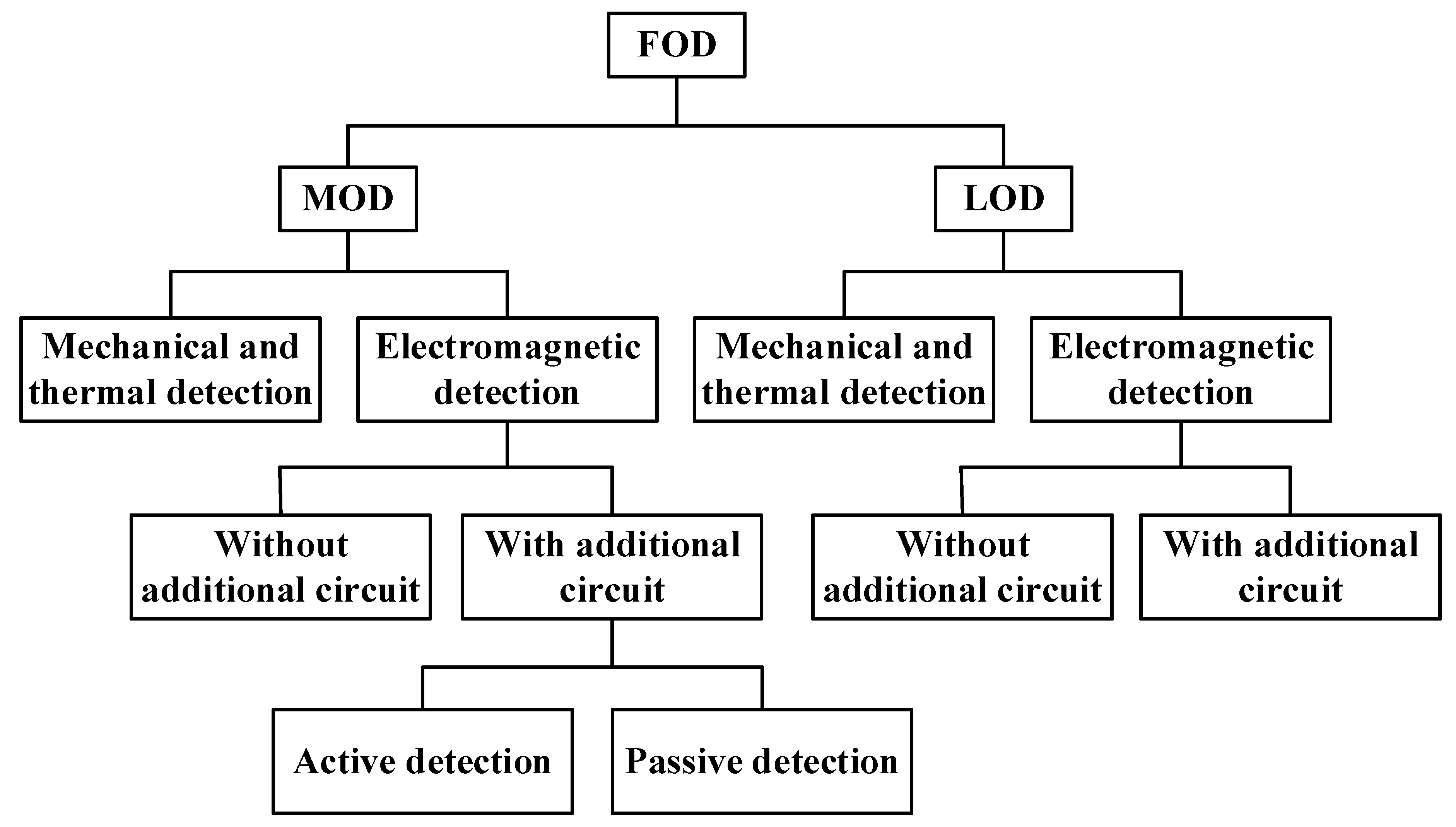
3. Foreign Object Detection Methods

This section discusses the state-of-the-art FOD methods for an EV wireless charging system based on the proposed foreign object models. According to the differences in the foreign object types and detection principles, FOD methods can be classified into several categories, as shown in Figure 5.
FOD methods can be divided into MOD and LOD methods according to type of foreign object. The detection methods include mechanical and thermal methods and electromagnetic methods, where the former methods focus on non-electromagnetic characteristics and the latter methods focus on the electromagnetic characteristics. According to whether an additional detection circuit is utilized, electromagnetic methods can be classified into two categories: methods with and without an additional circuit. Depending on whether the detection circuit is driven by a power source, the methods involving an additional circuit can be divided into active detection and passive detection methods.

3.1. Metal Object Detection Methods

Metal objects of different types and sizes can approach a WPT system, and their influences on the system are always different. Detection can be achieved based on the mechanical and thermal characteristics of the metal object, which lead to variations in space and temperature, or the electromagnetic characteristics of the metal object and the WPT system, which produce variations in the transmission performance. Therefore, MOD methods can be classified into two categories: mechanical and thermal detection methods and electromagnetic detection methods.
Mechanical and thermal detection methods focus on the variation of the whole framework of the WPT system, where the existence of a metal object always occupies the space and provides an independent heat source. Therefore, the light sensors [66], image processing [67,68], temperature sensors [69], and radar or sonar sensors [66,70] are always utilized in these methods to detect the mechanical and thermal signatures of the metal object, such as size, shape, temperature, and distance [56,66]. The metal object then can be validated by the output values of the detection sensor. These methods can be operated at all times, regardless of whether there is a receiving coil. However, the methods are mainly dependent on relative detection sensors and have been described in [66] and [71], and therefore, they will not be described in detail in this paper.
Electromagnetic detection methods focus on the electromagnetic effect of a metal object, where the existence of a metal object in a variable magnetic field will result in a power loss and a redistributed magnetic field, and the operating performance of the WPT system will change correspondingly. The metal object can, therefore, be detected from a changed system parameter or a changed EMF. According to whether an additional detection circuit is utilized, electromagnetic detection methods can be classified into two categories: methods with and without an additional circuit. Because the common metal objects are non-ferromagnetic, without loss of generality, we first assume the metal objects are non-ferromagnetic. The detection methods for ferromagnetic metal objects will be discussed later.

3.1.1. Detection Methods Without an Additional Circuit

Detection methods without an additional circuit utilize the main WPT system as the detection target, and a variation in the system parameters can be used to validate the existence of metal objects. For such methods, the detection theory can be analyzed through the proposed metal object model described in Section 2. The equivalent circuit of the metal object in a WPT system can be obtained as shown in Figure 6. The gray dashed line means that there is no additional detection circuit. When a metal object approaches a WPT system, it tends to couple with the transmission coils. In reality, the transmitter pad is always mounted under the ground, and the metal object tends to appear on the surface of the transmitting pad. Considering a large distance between the transmission coils, we assume that the metal object only affects the Tx coil and has no effect on the Rx coil. Therefore, the mutual inductance M23 can be neglected in the model and the effect of the metal object can be reflected to the transmitting coil as the variation of the internal resistance and inductance of the transmitting coil. R1eq and L1eq in Figure 6b represent the equivalent internal resistance and inductance of the transmitting coil considering the effect of the metal object. Moreover, the mutual inductance M12 may have a small variation with a variation of internal inductance of the transmitting coil. To simplify the analysis, we assume that the mutual inductance between the transmission coils does not change.
Assuming that the system operating frequency is ω, the circuit equation of Figure 6a can be expressed as:
{ V ˙ S = ( R S + R 1 + j ω L 1 + 1 j ω C 1 ) I ˙ 1 j ω M 12 I ˙ 2 j ω M 13 I ˙ 3 j ω M 12 I ˙ 1 = ( R 2 + R L + j ω L 2 + 1 j ω C 2 ) I ˙ 2 j ω M 13 I ˙ 1 = ( R 3 + j ω L 3 ) I ˙ 3
Considering the effect of the metal object on the Tx coil, the equivalent circuit equation of Figure 6b can be expressed as:
{ V ˙ S = ( R S + R 1 e q + j ω L 1 e q + 1 j ω C 1 ) I ˙ 1 j ω M 12 I ˙ 2 j ω M 12 I ˙ 1 = ( R 2 + R L + j ω L 2 + 1 j ω C 2 ) I ˙ 2
where,
{ R 1 e q = R 1 + ω 2 M 13 2 R 3 R 3 2 + ω 2 L 3 2 L 1 e q = L 1 ω 2 M 13 2 L 3 R 3 2 + ω 2 L 3 2
From Equations (11), (12) and (13), the effect of the metal object can be seen as an increase in the internal resistance and a decrease in the self-inductance of the Tx coil. The original system parameters then change correspondingly with the appearance of the metal object.
(a) Detection method based on an impedance deviation
From Equations (12) and (13), the input impedance of the WPT system can be expressed as:
Z i n = R 1 e q + ω 2 M 12 2 ( R 2 + R L ) ( R 2 + R L ) 2 + ( ω L 2 1 ω C 2 ) 2 + j ω ( L 1 e q ω M 12 2 ( ω L 2 1 ω C 2 ) ( R 2 + R L ) 2 + ( ω L 2 1 ω C 2 ) 2 ) + 1 j ω C 1
Therefore, the real and imaginary parts of the input impedance change due to the effect of the metal object, which provides an approach for metal object detection. In [72], an impedance deviation detection method was proposed, which utilized the deviation of the real impedance of the transmitting coil to validate the existence of a metal object. In this method, only voltage and current sensors within the WPT system are needed: no other sensors are needed.
(b) Detection method based on a voltage and current deviation
When the input impedance is affected by a metal object, the system voltage and current change correspondingly, which can act as detection parameters for MOD. With the reflection of the metal object and receiver to the transmitter, the equivalent circuit in Figure 6 can be simplified as shown in Figure 7.
From Equations (12), (13) and (14), the simplified circuit equation of Figure 7b can be expressed as:
V ˙ S = ( R S + R 1 e q _ a l l + j ω L 1 e q _ a l l + 1 j ω C 1 ) I ˙ 1
where,
{ L 1 e q _ a l l = L 1 ω M 12 2 ( ω L 2 1 ω C 2 ) ( R 2 + R L ) 2 + ( ω L 2 1 ω C 2 ) 2 ω 2 M 13 2 L 3 R 3 2 + ω 2 L 3 2 R 1 e q _ a l l = R 1 + ω 2 M 12 2 ( R 2 + R L ) ( R 2 + R L ) 2 + ( ω L 2 1 ω C 2 ) 2 + ω 2 M 13 2 R 3 R 3 2 + ω 2 L 3 2
From Equations (15) and (16), the current and voltage of the transmitting coil can be expressed as:
I ˙ 1 = V ˙ S R S + R 1 e q _ a l l + j ω L 1 e q _ a l l + 1 j ω C 1
V ˙ 1 = ( R 1 e q _ a l l + j ω L 1 e q _ a l l ) I ˙ 1
Therefore, the system voltage and current are affected by the metal object. In [73], a MOD method of monitoring and analyzing the working space of the supply current and transmitting coil voltage was proposed. When a large metal object appears and leads the voltage and current over a threshold value, the system then enters a fault mode and is shut down immediately. In addition, the drain waveform of the power switches also changes due to the inductive characteristics of the metallic object, where untuned metal objects may cause a different response in the drain waveform than the tuned receiver. Thus, the drain waveform deviation of power switches was measured in [74] to validate the existence of metal objects.
(c) Detection method based on a phase shift
From Equation (15), the phase between the voltage and current of the transmitting coil can be expressed as:
θ = arctan ω L 1 e q _ a l l 1 ω C 1 R S + R 1 e q _ a l l
When the voltage and current of the transmitter vary due to the presence of a metal object, a phase shift will always occur between them. Therefore, a phase shift detection method was proposed in [75], which tracked the voltage and current of the transmitting coil and calculated the corresponding phase shift. If the measured value exceeds a predetermined threshold, the existence of the metal object can be determined, and the system will be adjusted to a safe operating condition. The experimental results presented in [75] showed that a phase shift of 7°, 10° and 15° can be obtained when a can, iron bottle and pot object is placed on the transmitting coil separately.
(d) Detection method based on a resonance frequency deviation
From Equations (15), the resonance frequency of the WPT system with the effect of a metal object can be expressed as:
f r = 1 2 π L 1 e q _ a l l C 1
We can know from Equation (16) that the equivalent internal inductance of transmitting coil L 1 e q _ a l l tends to decrease with the effect of a metal object. Therefore, the resonance frequency tends to increase and can be used to detect the metal object. In [76] and [56,77,78], resonance frequency deviation detection methods were proposed that involved monitoring and measuring the resonance frequency of the transmitting coil. In [76], the frequency tracking power was utilized to make the system operate in the resonant state, and the resonance frequency was calculated through a single-chip detection system. In [56,77,78], a self-tuning controller was utilized to synchronize the switching power converter with the resonant current and measure the resonance frequency. By comparing the measured value with the normal value, the existence of a metal object can then be determined when the resonance frequency deviation exceeds a threshold, and the switching signal can then be disabled.
(e) Detection method based on a Q factor deterioration
From Equations (4), (5) and (6), the quality factor varies with changes in the input impedance and resonance frequency, which can be used to reveal the appearance of metal objects. In [79], a Q factor deterioration detection method was proposed, where the Q factor of the receiving coil was measured to validate nearby metal objects. The equivalent circuit is shown in Figure 8.
In Figure 8, v c 1 and v c 2 represent the voltage on both side of resonance capacitance C 2 . L 2 e q and R 2 e q represent the equivalent self-inductance and internal resistance of the receiving coil considering the reflected metal object, which can be expressed as:
{ R 2 e q = R 2 + R 3 ω 2 M 23 2 R 3 2 + ω 2 L 3 2 L 2 e q = L 2 L 3 ω 2 M 23 2 R 3 2 + ω 2 L 3 2
From Equations (2), (5) and (21), the resonance angular frequency ω r and Q factor of the receiving coil can be expressed as:
ω r = 1 L 2 e q C 2
Q = ω r L 2 e q R 2 e q = 1 R 2 e q L 2 e q C 2 = 1 R 2 + R 3 ω r 2 M 23 2 R 3 2 + ω r 2 L 3 2 L 2 L 3 ω r 2 M 23 2 R 3 2 + ω r 2 L 3 2 C 2
It can be seen from Equation (21) that under the effect of the metal object, the equivalent internal inductance decreases while internal resistance increases. Therefore, the resonance frequency tends to increase while the Q factor decreases, and the Q factor can be used as a detection parameter. In [79], the Q factor of the receiving coil was monitored by measuring the voltage on both sides of the resonance capacitance. The receiver acts as an LC high-pass filter, and the Q factor can be expressed as the peak level of ( v c 2 v c 1 ) / v c 1 , where,
v c 2 v c 1 v c 1 = s 2 s 2 + s ω Q + ω 2
When ω is equal to the resonance frequency ω r , Equation (24) can be written as:
| v c 2 v c 1 v c 1 | = | v c 2 v c 1 | | v c 1 | = Q
By varying the frequency of the power source, the peak level of | v c 2 v c 1 | / | v c 1 | can be searched, which is known as the Q factor. The metal object can thus be determined by comparing the measured Q factor with the original value without the metal object.
(f) Detection method based on a power loss and transmission efficiency deterioration
As described above, the existence of a metal object will cause a power loss due to the eddy current induced inside the object. Moreover, the changed input impedance, voltage, current, phase shift, resonance frequency and quality factor will lead to impedance mismatching, which may greatly decrease the transmission efficiency of the WPT system. As a result, the transmitter tends to deliver more power to sustain the intended power of the receiver. Therefore, the power loss and transmission efficiency can be used to detect the metal object. In [80], a power loss detection method was proposed for MOD in a low-power WPT system, which is also suitable for a high-power system. This method uses mathematical regression analysis to find the relationship between the system parameters and the power loss in the WPT system. By calculating the power loss and comparing it with the measured input and output powers, the presence of metal objects then be determined by the discrepancy in the power. In [55], a detection method based on a transmission efficiency deterioration was proposed that involved measuring the frequency characteristics of the transmission performance of a four-coil WPT system. With this method, as a metal object approaches the transmission coils, the transmission characteristics change, where the frequencies of the minimized reflection of the transmission coils increase and the number of such frequencies changes. By measuring the value and number of such frequencies, the existence of the metal object can then be determined.
In conclusion, detection methods without an additional circuit focus on variations in the original system performance due to the metal object, where the changed system parameters, including the input impedance, voltage, current, phase shift, resonance frequency, Q factor, power loss and transmission efficiency, act as detection parameters. Apart from this method, the other way to detect a metal object is to employ a detection method that utilizes an additional detection circuit to detect the electromagnetic effect of the metal object.

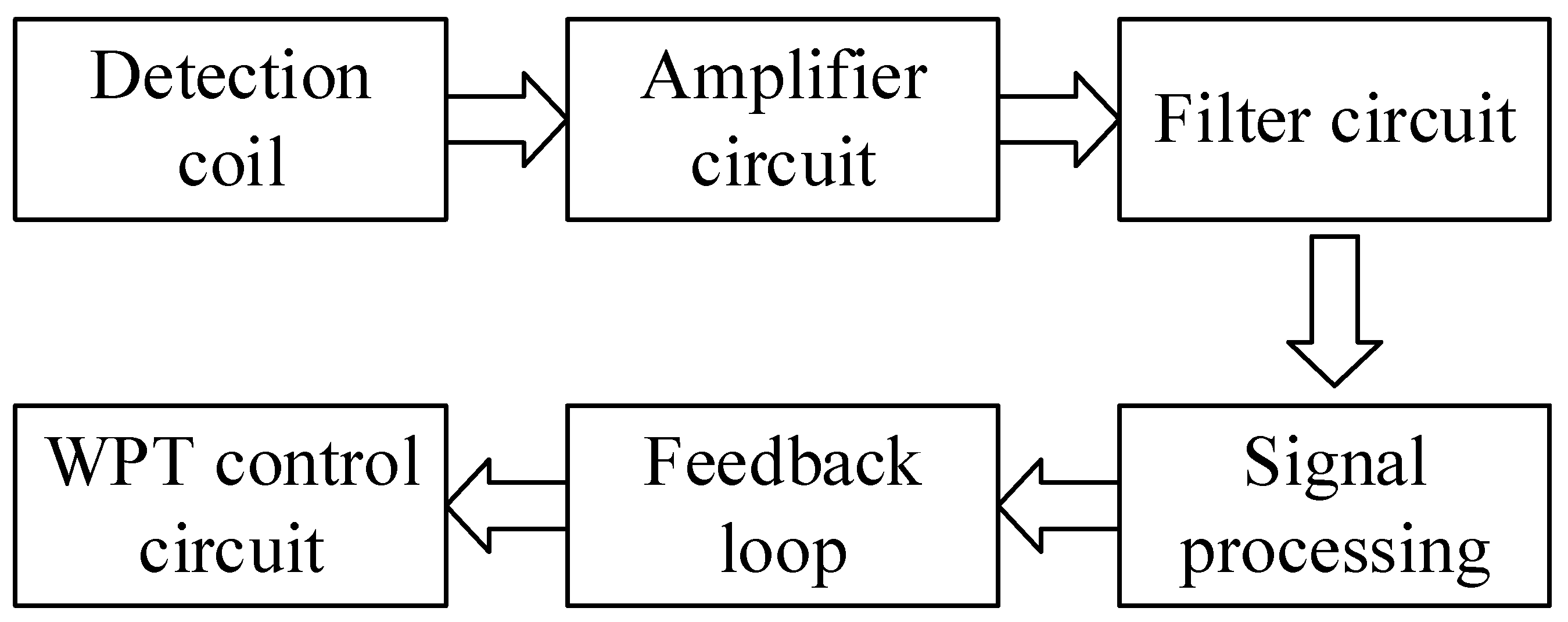
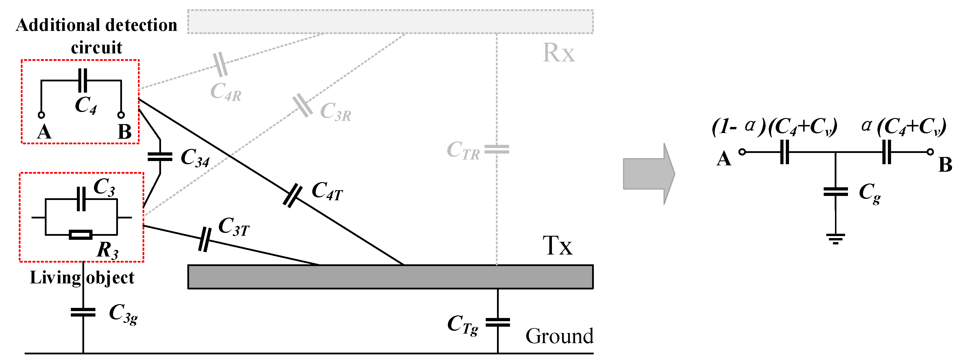
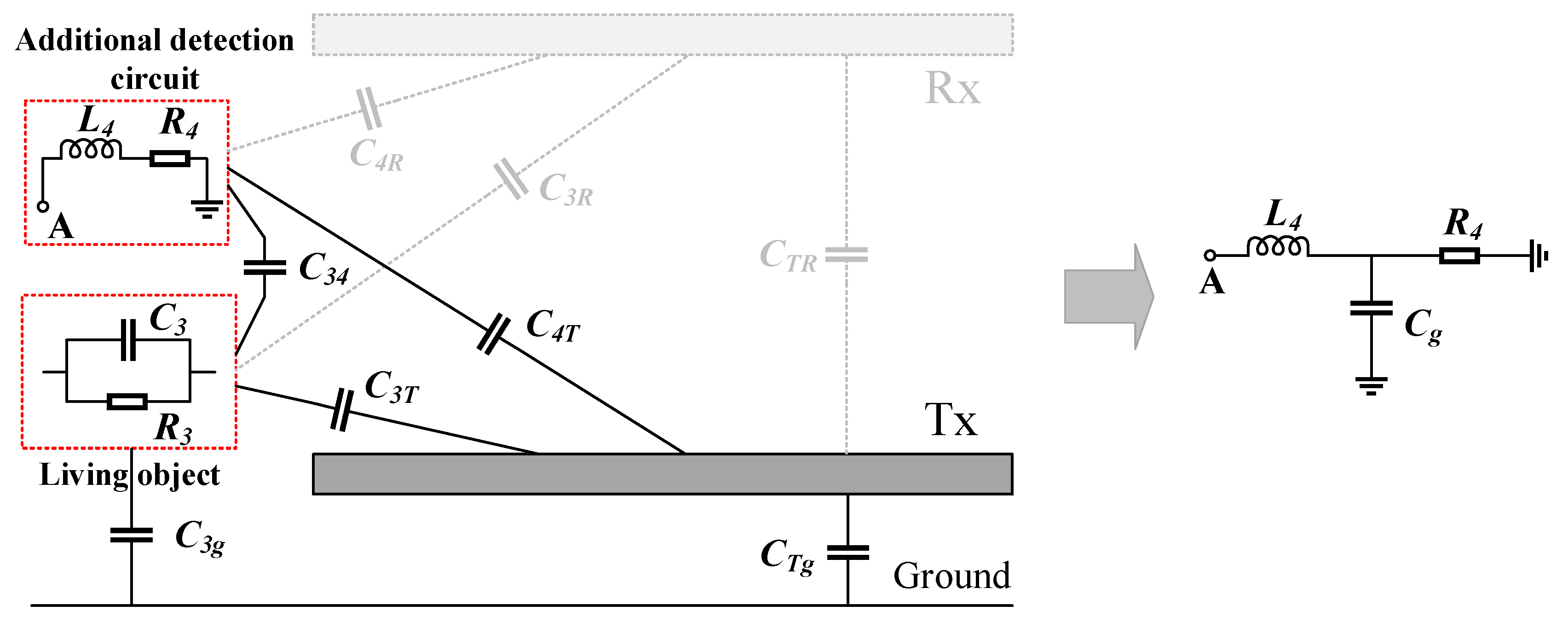
3.1.2. Detection Methods with An Additional Circuit

Detection methods with an additional circuit focus on the EMF coupling effect of the metal object, where a metal object in a variable magnetic field tends to couple with the field-generating coil and disturb the magnetic field [55,76,81,82]. In this method, an additional inductive circuit is always utilized as an auxiliary detection sensor, which can couple with the metal object or measure the changed EMF between the transmission coils. Depending on whether the magnetic field is generated by the additional detection circuit or the transmission coils, detection methods with an additional circuit can be classified into active and passive detection methods.
In active detection methods, the additional detection circuit is always driven by a power source, which can generate a magnetic field and couple with the metal object. As described above, the metal object may affect the circuit impedance and absorb energy from the magnetic field. Therefore, the metal object can be detected by a deviation in the circuit impedance or transferred power. Unlike active detection methods, passive detection methods utilize an additional detection circuit without a power source to measure the change in the EMF between the transmission coils, where the existence of the metal object induces a voltage deviation. Therefore, a metal object can be detected by deviations in the active impedance, active power and passive induced voltage.
(a) Detection method based on an active impedance deviation
When a metal object is present in the magnetic field generated by the additional detection circuit, a magnetic coupling effect occurs. The effect of the metal object can be seen as a variation in the equivalent internal resistance and self-inductance of the detection circuit [83,84]. The equivalent circuit is shown in Figure 9.
With the operating frequency ω, the equivalent internal resistance and self-inductance can be expressed as:
{ R 4 e q = R 4 + R 3 ω 2 M 34 2 R 3 2 + ω 2 L 3 2 L 4 e q = L 4 L 3 ω 2 M 34 2 R 3 2 + ω 2 L 3 2
It can be seen from Equation (26) that the equivalent internal resistance increases due to the presence of the metal object, while the self-inductance decreases. The metal object can then be detected from the circuit impedance deviation. In [83] and [84], a detection method based on a coil impedance deviation was proposed, which utilized the variation in the self-inductance of a sensing circuit mounted on the Tx pad to realize the metal object detection. The sensing pattern consisted of multiple loop coil sets, with each loop coil set containing two coils connected in series with opposite polarities to cancel the induced voltage inside the coil set generated by the transmission coils. In this method, the sensing pattern involves a parallel resonant circuit driven by a current source and employs a mistuned operating frequency near the −3 dB point to increase the detection sensitivity. If a metal object is present, the object will tend to couple with the sensing pattern, and the self-inductance of the sensing pattern will decrease, leading to a decrease in the output voltage of the parallel resonant circuit. By measuring the output voltage, the existence of the metal object can be validated.
(b) Detection method based on an active power deviation
In addition to the circuit impedance, the transferred power of the coil can also be used to detect a metal object. In [74], the transmission power of the additional detection circuit was monitored to indicate the existence of metal objects. The additional detection coil was always utilized and placed near the transmitting coil, which was driven at a frequency slightly different from the system resonance frequency. In this case, when a metal object appears, the object tends to absorb energy from the magnetic field generated by the detection coil, which leads to a variation in the transferred power of the coil. Therefore, the metal object can be detected by monitoring the power transmitted from the additional detection coil.
(c) Detection method based on a passive induced voltage deviation
The detection method based on a passive induced voltage deviation focuses on the electromagnetic coupling effect of the metal object, where the change in the EMF causes an induced voltage deviation of the additional detection coil [58,59,60,85,86,87,88,89,90,91,92] or the tunable magnetoresistive (TMR) sensor [57]. The equivalent circuit is shown in Figure 10.
In [58,59,60,85,86,87,88,89,90,91,92], the induced voltage deviation of the additional detection coil was always utilized to verify the distorted EMF between the transmission coils in the presence of metal objects. The detection coil was always located on the transmitting pad and contained two reverse direction or symmetric direction coil loops to cancel the induced voltage generated by the transmitting coil. When a metal object was present, the redistributed magnetic flux passing through the coil loops would cause an induced voltage deviation, thus constituting an approach for MOD. However, the coil structures in these references were different. In [85], multiple open-circuited, single-turn sensing coils placed above the Tx worked as the detection coil. In [86], a group of two divided coil loops or two reverse-direction overlapped coil loops acted as the detection coil, while in [59,60,87,88], many pairs of non-overlapped coil loops were installed in parallel as the detection coil, with each pair of coil loops having two reverse-direction symmetric coils that could be divided or connected in reverse. The integrated non-overlapped coil structure is proposed in [89] and the statistical model of induced voltage in detection coils are used for MOD. These detection coils can be fabricated on the printed circuit board (PCB) layer. The overlapped coil structure requires at least two layers, while the non-overlapped coil structure requires only one layer. The detection coil proposed in [58] consisted of many turns of two parallel symmetrical half-circle coils overlapping with reverse directions. The symmetrical configurations of the square coils connected in reverse direction are proposed in [90,91,92], where a double-layer balanced configuration is used in [90], a two-layer centrosymmetric configuration is used in [91], a single layer symmetrical configuration with a non-symmetrical center to eliminate the blind zones is proposed in [92].
In addition to the detection coil, a TMR sensor matrix was proposed to measure the change in the EMF in reference [57]. The sensor matrix was mounted below the receiving coil, and the magnetic flux density distribution of the whole flux plane was measured. The existence of a metal object can then be distinguished by the DC magnetic field offset caused by the distorted magnetic flux, and the location can be obtained by analyzing the voltage output of the sensor matrix.
In conclusion, detection methods with the additional circuit focus on the coupling effect of the metal object on the additional detection circuit or the WPT system. The detection circuit is always followed by an amplifier circuit, a filter circuit, a signal-processing circuit and a feedback loop to the WPT control system. These circuits always have a high input impedance to reduce the detection circuit current and prevent an impact on the transmission coils. The block diagram of the additional detection system is shown in Figure 11.
For the ferromagnetic metal object, it can be regarded as a ferrite. When the metal object gets close to the transmission coils, the equivalent internal inductance of the coils may be increased due to permeability and conductivity of the metal object, and the equivalent internal resistance increased due to the eddy current inside the metal object. Then the coil impedance may be changed, which leads to a variation of coil voltage and current, and a phase shift between them. The quality factor of the coil and the system resonant frequency also changes. All of these would cause a mistuning and decrease the transmission efficiency. The magnetic field also can be distributed by the high permeability of the ferromagnetic metal objects. Therefore, the detection methods that applied for non-ferromagnetic metal objects can also be used for ferromagnetic metal object.
The effect of a metal object on the WPT system depends on the size, shape, material and location of the metal object, which have been researched. In [93], the effect of the metal object size on the WPT system was studied. It shows that increasing the size of the metal object significantly increases the foreign object impact. In [94], the effects of different types of metal objects on a WPT system with different locations were studied comparatively. It is shown that non-ferromagnetic metals always lead to a high frequency shift and a lower resistive loss, while ferromagnetic metals always produce a low frequency shift and a high eddy current loss. The influence of the metal object location on the self-inductance, mutual inductance and resonance frequency of the WPT system was researched in [56,82], where the variation increased as the metal object became closer to the coil, and the maximum variation always occurred on the coil but not on the exact center because the flux density in the center may cancel it out. All these results show that the impact of a metal object in a WPT system is extremely sensitive to the characteristics of the metal object. Therefore, the effective conditions of different MOD methods must be carefully evaluated at specific cases.
General MOD methods are summarized in Table 1.
The operating time of the detection methods also needs to be considered. If the detection method can be implemented before charging, the metal object can then be found and removed before the object absorbs energy from the WPT system. However, only the methods with an additional driving system can be implemented before charging, such as the mechanical and thermal detection methods [66,67,68,69,70], active detection methods [74,83,84] and resonance frequency detection method [56]. The other detection methods, which correlate with the charging state of the WPT system, can only be implemented while charging. To avoid a threat associated with the metal object while charging, the detection methods need to operate during the whole charging process.

3.2. Lving Object Detection Methods

A living object that is exposed to the strong EMF generated by the transmission coils of a WPT system may exhibit symptoms such as body heating, blood pressure changes, whirling, nausea and fatigue [62,95,96,97]. At the same time, the transmission performance of the WPT system may be affected by the existence of the living object. Therefore, living objects should be detected during wireless charging. Living objects can be detected based on the mechanical and thermal characteristics or the electromagnetic characteristics of the living object. LOD methods can thus be classified into two categories: mechanical and thermal detection methods and electromagnetic detection methods.

3.2.1. Mechanical and Thermal Detection Methods

The mechanical and thermal detection methods used for MOD are also suitable for LOD, where the light sensors [66], imaging processing [67,68], temperature sensors [66], and radar or sonar sensors [66,70,98,99] are always utilized to validate the presence of a living object based on size, shape, temperature and distance. These methods focus on variations in the space occupied by the living object and the temperature associated with the living object. These methods can be implemented before or during charging, and the detection results mainly rely on relative detection sensors. Such methods have been proposed in [66] and [71] but are not described in detail in this paper.

3.2.2. Electromagnetic Detection Methods

Electromagnetic detection methods focus on the electric coupling effect of the living object, where capacitive coupling always occurs due to the capacitive characteristic of the living object. This detection method can be demonstrated and analyzed by the living object model proposed in Section 2. Depending on whether an additional detection circuit exists, the electromagnetic detection methods can be classified into two categories: methods with and without an additional circuit.
(a) Detection methods without an additional circuit
As shown in Figure 12, the grey dashed line means there is no additional detection circuit. When a living object that is capacitive and not tuned to the resonance frequency approaches the transmission coils, capacitive coupling always occurs, which leads to a change in the drain waveform of the power switches relative to that of a tuned receiver. Therefore, the drain waveform of the power switches can be used to detect nearby living objects.
In Figure 12, C T R _ e q and C T g _ e q represent the equivalent mutual capacitance between the transmission coils and the ground effect of the Tx pad considering the existence of the living object. In [74], the drain waveform of the power switches was measured and compared with the original waveform, and the living object could then be verified from the deviation in the drain waveform.
(b) Detection methods with an additional circuit
Detection methods with an additional circuit focus on the mutual capacitance between the living object and the additional detection circuit, where a detection capacitor [62,69,100] or detection coil [101] is always utilized. When a living object is in the vicinity of the detection circuit, the coupling effect always produces a variation in the circuit impedance. The living object can then be detected from such impedance deviations.
In [62,69,100], a capacitor with a special shape was utilized as the additional detection sensor. In [69], a length of wire was employed as the capacitive element to measure the capacitance deviation with or without the living object. In [62,100], a comb pattern capacitor was used as the sensing pattern, which was mounted on the transmitting pad and driven by a power source. With this approach, when a living object approaches the sensing pattern, a mutual capacitance occurs that always produces a capacitance deviation. Considering the mutual capacitance between the living object and the ground, the equivalent circuit is shown in Figure 13 [62,102].
C v represents the capacitance variation of the sensing pattern in the presence of a living object. C g represents the mutual capacitance between the sensing pattern and the ground, which can be negligible when the living object appears on the surface of the transmitting pad. α represents the difference coefficient of the sensor electrodes, which is always 0.5 [64,103]. To measure the capacitance variation, a single comb pattern capacitor and an active RC integrator were utilized in [62] to detect the minimal capacitance change. A multiple comb pattern capacitor and a parallel resonant circuit were utilized in [100] to improve the detection sensitivity. The living object could then be determined by the impedance deviation of the detection circuit.
In addition to the detection capacitor, a detection coil can also be used for LOD. In [101], a detection coil was used as the capacitive sensor, which was mounted on the Tx pad and driven by a power source. The detection coil tends to couple with the living object by the mutual capacitance, producing a variation in the circuit impedance. Considering the ground effect of the living object, the equivalent circuit is shown in Figure 14. By measuring the impedance variation of the detection coil, the presence of a living object can then be validated
In conclusion, the presence of a living object close to a WPT system can be verified based on the physical and thermal characteristics of the living object or the electric field coupling effect of the living object on the WPT system or the additional detection circuit. General LOD methods are summarized in Table 2.
The operating time of a LOD method also needs to be considered. To prevent the living object from experiencing harmful effects due to the strong EMF, the detection method should be implemented before charging, as with the mechanical and thermal detection methods [66,67,70,98,99] and detection methods with an additional circuit [62,69,100,101]. Considering that a living object may approach the transmission coils while charging, all the detection methods should be implemented during the whole charging process.

3.3. Conclusions

Metal and living objects that approach a WPT system and are exposed to a strong EMF may produce changes in the transmission performance and cause safety problems, which should be forbidden in EV wireless charging. In addition, the detection method should be implemented during the whole charging process. The discussed MOD and LOD methods can be achieved based on the mechanical and thermal characteristics or electromagnetic characteristics of the foreign object. The mechanical and thermal detection methods focus on the volume and temperature associated with the foreign object. These methods are suitable for both MOD and LOD and can be implemented before or during charging. The electromagnetic detection methods focus on the inductive or capacitive coupling effect of the foreign object on the WPT system or the additional detection circuit and can be categorized based on whether an additional circuit is employed. The detection methods without an additional circuit utilize changes in system parameters, such as impedance, voltage, current, phase shift, resonance frequency, Q factor, power loss and transmission efficiency, to validate the existence of the foreign object. The detection methods with the additional circuit include active and passive detection methods. The active detection methods utilize detection coils or detection capacitors driven by a power source to couple with the foreign object and validate the existence of the foreign object based on the variation of the detection circuit. The passive detection methods always utilize detection coils to measure the change in the EMF between the transmission coils due to a metal object. By implementing these detection methods before or during charging, a foreign object can then be detected.

4. Conclusions and Future Challenges

This paper reviews the major MOD and LOD methods and analyzes the methods within a unified framework based on the proposed metal object and living object models. This section discusses the advantages and disadvantages of FOD methods in terms of cost, occupied space, sensitivity and complexity. The future challenges of FOD in EV wireless charging are also analyzed.
The FOD methods described above contain mechanical and thermal detection methods and detection methods with and without an additional circuit. The mechanical and thermal detection methods focus on the mechanical and thermal signatures of foreign objects and need detection sensors. These methods are independent of the WPT system and the type of foreign object. However, the detection sensor is always relatively expensive and requires additional working space, and the detection sensitivity is always affected by the environment.
The detection methods without an additional circuit, which focus on the variation of system parameters affected by foreign objects, have mostly been proposed for MOD and implemented during charging. These methods are always cost-effective and easy to implement. However, the state variation is always relatively weak compared to that of a high-power WPT system, and the methods are not always sensitive to small objects. Moreover, the detection results are always affected by the misalignment of the receiver coil and the load condition, which can also cause changes in the system parameters.
The detection methods with an additional circuit, which are the most popular, focus on the EMF coupling effect of foreign objects and a detection coil or capacitor are always utilized as the detection equipment. These methods have a relatively higher detection sensitivity than the other two detection methods, and both the detection coil and capacitor are easy to mount. Among them the active detection methods are suitable for both MOD and LOD and can be implemented before or during charging. The passive detection methods are only suitable for MOD and can only be implemented during charging. In addition, these methods always require a signal-processing circuit, and the active detection methods always require an extra driving circuit, which increases the complexity of the WPT system and may be affected by the strong EMF. Moreover, although the sensitivity is relatively higher than that of the other methods, the detection accuracy needs to be improved for small objects.
The characteristics of the major FOD methods are shown in Table 3, and the suitable foreign object types and operating times of the major FOD methods are shown in Table 4.
Comprehensively considering the cost, occupied space, sensitivity and complexity, the detection methods that employ the additional circuit are recommended for EV wireless charging. The active detection methods are recommended, because they are suitable for both MOD and LOD, and can be operated before or during charging. The detection signal variation can be 40% for MOD [83,84] and 30% for LOD [62,100], which are large enough for FOD. However, the active methods always require an extra driving circuit. Considering the cost and complexity, a combination of active and passive detection methods may be a future development direction of the FOD technology.
Although various detection methods have been proposed, there are also some challenges for FOD in EV wireless charging.
First, the recent FOD methods have mainly been proposed for inductive power transfer (IPT) systems rather than capacitive power transfer (CPT) applications. With the increase in applications of the CPT system in EV wireless charging, FOD in the CPT system needs to be studied. For the CPT system, a strong electric field is generated between the transmission metal plates, which may be separated by a long distance. When a foreign object is present, the capacitive coupling and transmission performance of the CPT system will be affected. Moreover, when a living object approaches the transmission plates, it will experience a strong electric field, and if the living object touches a metal plate with a high voltage, a current will flow inside the living body to the ground [104,105,106,107,108]. Therefore, to maintain the transmission performance and prevent safety problems, FOD in the CPT system needs to be considered in the future.
Second, the evaluation of the FOD methods needs to be researched in the future. Currently, it is difficult to compare the performance of different FOD studies fairly, because foreign objects have different properties, such as size, shape, and location, which may lead to quite different results. A universal metric to evaluate the capability of FOD methods would greatly promote the development of this technology, and standardized specific test scenarios would also be extremely helpful.
Finally, the detection sensitivity and accuracy should be improved in the future. For example, increasing the detection sensitivity of the detection methods without an additional circuit and improving the detection accuracy of the detection methods with the additional circuit would be worthwhile. With a compromise between cost, occupied space and complexity, the detection sensitivity and accuracy should be improved as much as possible, which would eventually promote the application of this technology.

Author Contributions

Article outline, S.L. (Siqi Li), conceptualization and methodology, J.X., X.Y. and J.L.; investigation, J.X., X.Y. and X.C.; formal analysis and writing—original draft preparation, J.X. and X.Y.; writing—review and polish, S.L. (Sizhao Lu) and L.M.F.-R. All authors have read and agreed to the published version of the manuscript.

Funding

This work was supported in part by the National Natural Science Foundation of China under Grant No. 51607081.

Conflicts of Interest

The authors declare no conflict of interest.

References

  1. Kurs, A.; Karalis, A.; Moffatt, R.; Joannopoulos, J.D.; Fisher, P.; Soljačić, M. Wireless power transfer via strongly coupled magnetic resonances. Science 2007, 317, 83–86. [Google Scholar] [CrossRef] [PubMed] [Green Version]
  2. Yang, Y.; El Baghdadi, M.; Lan, Y.; Benomar, Y.; Van Mierlo, J.; Hegazy, O. Design methodology, modeling, and comparative study of wireless power transfer systems for electric vehicles. Energies 2018, 11, 1716. [Google Scholar] [CrossRef] [Green Version]
  3. Dobrzan´ ski, D. Overview of currently used wireless electrical vehicle charging solutions. Inform. Autom. Pomiary Gospod. Ochr. Środowiska 2018, 8, 47–50. [Google Scholar] [CrossRef]
  4. Patil, D.; McDonough, M.K.; Miller, J.M.; Fahimi, B.; Balsara, P.T. Wireless power transfer for vehicular applications: Overview and challenges. IEEE Trans. Transp. Electrif. 2018, 4, 3–37. [Google Scholar] [CrossRef]
  5. Lu, F.; Zhang, H.; Hofmann, H.; Mi, C.C. An inductive and capacitive combined wireless power transfer system with LC-compensated topology. IEEE Trans. Power Electron. 2016, 31, 8471–8482. [Google Scholar] [CrossRef]
  6. Tran, D.H.; Vu, V.B.; Choi, W. Design of a high-efficiency wireless power transfer system with intermediate coils for the on-board chargers of electric vehicles. IEEE Trans. Power Electron. 2018, 33, 175–187. [Google Scholar] [CrossRef]
  7. Moon, S.; Moon, G. Wireless power transfer system with an asymmetric four-coil resonator for electric vehicle battery chargers. IEEE Trans. Power Electron. 2016, 31, 6844–6854. [Google Scholar]
  8. Moon, S.; Kim, B.C.; Cho, S.Y.; Ahn, C.H.; Moon, G.W. Analysis and design of a wireless power transfer system with an intermediate coil for high efficiency. IEEE Trans. Ind. Electron. 2014, 61, 5861–5870. [Google Scholar] [CrossRef]
  9. Zhang, J.; Yuan, X.; Wang, C.; He, Y. Comparative analysis of two-coil and three-coil structures for wireless power transfer. IEEE Trans. Power Electron. 2017, 32, 341–352. [Google Scholar] [CrossRef]
  10. Del Toro García, X.; Vázquez, J.; Roncero-Sánchez, P. Design, implementation issues and performance of an inductive power transfer system for electric vehicle chargers with series–series compensation. IET Power Electron. 2015, 8, 1920–1930. [Google Scholar] [CrossRef]
  11. Li, W.; Zhao, H.; Li, S.; Deng, J.; Kan, T.; Mi, C.C. Integrated LCC compensation topology for wireless charger in electric and plug-in electric vehicles. IEEE Trans. Ind. Electron. 2015, 62, 4215–4225. [Google Scholar] [CrossRef]
  12. Li, S.; Li, W.; Deng, J.; Nguyen, T.D.; Mi, C.C. A double-sided LCC compensation network and its tuning method for wireless power transfer. IEEE Trans. Veh. Technol. 2015, 64, 2261–2273. [Google Scholar] [CrossRef]
  13. Zhang, W.; Mi, C.C. Compensation topologies of high-power wireless power transfer systems. IEEE Trans. Veh. Technol. 2016, 65, 4768–4778. [Google Scholar] [CrossRef]
  14. Bosshard, R.; Kolar, J.W.; Mühlethaler, J.; Stevanovic´, I.; Wunsch, B.; Canales, F. Modeling and η-α-pareto optimization of inductive power transfer coils for electric vehicles. IEEE J. Emerg. Sel. Top. Power Electron. 2015, 3, 50–64. [Google Scholar] [CrossRef]
  15. Miller, J.M.; Daga, A. Elements of wireless power transfer essential to high power charging of heavy duty vehicles. IEEE Trans. Transp. Electrif. 2015, 1, 26–39. [Google Scholar] [CrossRef]
  16. Kan, T.; Nguyen, T.; White, J.C.; Malhan, R.K.; Mi, C.C. A new integration method for an electric vehicle wireless charging system using LCC compensation topology: Analysis and design. IEEE Trans. Power Electron. 2017, 32, 1638–1650. [Google Scholar] [CrossRef]
  17. Chen, W.; Liu, C.; Lee, C.H.; Shan, Z. Cost-effectiveness comparison of coupler designs of wireless power transfer for electric vehicle dynamic charging. Energies 2016, 9, 906. [Google Scholar] [CrossRef] [Green Version]
  18. Luo, Z.; Wei, X. Analysis of square and circular planar spiral coils in wireless power transfer system for electric vehicles. IEEE Trans. Ind. Electron. 2018, 65, 331–341. [Google Scholar] [CrossRef]
  19. Hsieh, Y.; Lin, Z.; Chen, M.; Hsieh, H.; Liu, Y.; Chiu, H. High-efficiency wireless power transfer system for electric vehicle applications. IEEE Trans. Circuits Syst. II-Express Briefs 2017, 64, 942–946. [Google Scholar] [CrossRef]
  20. Li, H.; Li, J.; Wang, K.; Chen, W.; Yang, X. A maximum efficiency point tracking control scheme for wireless power transfer systems using magnetic resonant coupling. IEEE Trans. Power Electron. 2015, 30, 3998–4008. [Google Scholar] [CrossRef]
  21. Miller, J.M.; Onar, O.C.; Chinthavali, M. Primary-side power flow control of wireless power transfer for electric vehicle charging. IEEE J. Emerg. Sel. Top. Power Electron. 2015, 3, 147–162. [Google Scholar] [CrossRef]
  22. Gao, Y.; Ginart, A.; Farley, K.B.; Tse, Z.T.H. Misalignment effect on efficiency of wireless power transfer for electric vehicles. In Proceedings of the 2016 IEEE Applied Power Electronics Conference and Exposition (APEC), Long Beach, CA, USA, 20–24 March 2016; pp. 3526–3528. [Google Scholar]
  23. Aldhaher, S.; Luk, P.C.; Whidborne, J.F. Electronic tuning of misaligned coils in wireless power transfer systems. IEEE Trans. Power Electron. 2014, 29, 5975–5982. [Google Scholar] [CrossRef] [Green Version]
  24. Mou, X.; Groling, O.; Sun, H. Energy-efficient and adaptive design for wireless power transfer in electric vehicles. IEEE Trans. Ind. Electron. 2017, 64, 7250–7260. [Google Scholar] [CrossRef] [Green Version]
  25. Karakitsios, I.; Karfopoulos, E.; Madjarov, N.; Bustillo, A.; Ponsar, M.; Del Pozo, D.; Marengo, L. An integrated approach for dynamic charging of electric vehicles by wireless power transfer-lessons learned from real-life implementation. SAE Int. J. Altern. Powertrains 2017, 6, 15–24. [Google Scholar] [CrossRef] [Green Version]
  26. Regensburger, B.; Kumar, A.; Sinha, S.; Doubleday, K.; Pervaiz, S.; Popovic, Z.; Afridi, K. High-performance large air-gap capacitive wireless power transfer system for electric vehicle charging. In Proceedings of the 2017 IEEE Transportation Electrification Conference and Expo (ITEC), Chicago, IL, USA, 22–24 June 2017; pp. 638–643. [Google Scholar]
  27. Li, S.; Liu, Z.; Zhao, H.; Zhu, L.; Shuai, C.; Chen, Z. Wireless Power Transfer by Electric Field Resonance and Its Application in Dynamic Charging. IEEE Trans. Ind. Electron. 2016, 63, 6602–6612. [Google Scholar] [CrossRef]
  28. Bi, Z.; Kan, T.; Mi, C.C.; Zhang, Y.; Zhao, Z.; Keoleian, G.A. A review of wireless power transfer for electric vehicles: Prospects to enhance sustainable mobility. Appl. Energy 2016, 179, 413–425. [Google Scholar] [CrossRef] [Green Version]
  29. Mi, C.C.; Buja, G.; Choi, S.Y.; Rim, C.T. Modern advances in wireless power transfer systems for roadway powered electric vehicles. IEEE Trans. Ind. Electron. 2016, 63, 6533–6545. [Google Scholar] [CrossRef]
  30. Shin, J.; Shin, S.; Kim, Y.; Ahn, S.; Lee, S.; Jung, G.; Jeon, S.J.; Cho, D.H. Design and implementation of shaped magnetic-resonance-based wireless power transfer system for roadway-powered moving electric vehicles. IEEE Trans. Ind. Electron. 2014, 61, 1179–1192. [Google Scholar] [CrossRef]
  31. Buja, G.; Bertoluzzo, M.; Dashora, H.K. Lumped track layout design for dynamic wireless charging of electric vehicles. IEEE Trans. Ind. Electron. 2016, 63, 6631–6640. [Google Scholar] [CrossRef]
  32. Tavakoli, R.; Pantic, Z. Analysis, design, and demonstration of a 25-kW dynamic wireless charging system for roadway electric vehicles. IEEE J. Emerg. Sel. Top. Power Electron. 2018, 6, 1378–1393. [Google Scholar] [CrossRef]
  33. Limb, B.J.; Bradley, T.H.; Crabb, B.; Zane, R.; McGinty, C.; Quinn, J.C. Economic and environmental feasibility, architecture optimization, and grid impact of dynamic charging of electric vehicles using wireless power transfer. In Proceedings of the 6th Hybrid and Electric Vehicles Conference (HEVC 2016), London, UK, 2–3 November 2016; pp. 1–6. [Google Scholar]
  34. Miller, J.M.; Jones, P.T.; Li, J.; Onar, O.C. ORNL experience and challenges facing dynamic wireless power charging of ev’s. IEEE Circuits Syst. Mag. 2015, 15, 40–53. [Google Scholar] [CrossRef]
  35. Zhou, S.; Mi, C.C. Multi-paralleled LCC reactive power compensation networks and their tuning method for electric vehicle dynamic wireless charging. IEEE Trans. Ind. Electron. 2016, 63, 6546–6556. [Google Scholar] [CrossRef]
  36. Lu, F.; Zhang, H.; Hofmann, H.; Mi, C.C. A dynamic charging system with reduced output power pulsation for electric vehicles. IEEE Trans. Ind. Electron. 2016, 63, 6580–6590. [Google Scholar] [CrossRef]
  37. Jiang, H.; Brazis, P.; Tabaddor, M.; Bablo, J. Safety considerations of wireless charger for electric vehicles—A review paper. In Proceedings of the 2012 IEEE Symposium on Product Compliance Engineering Proceedings, Portland, OR, USA, 5–7 November 2012; pp. 1–6. [Google Scholar]
  38. International Commission on Non-Ionizing Radiation Protection. Guidelines for limiting exposure to time-varying electric and magnetic fields (1 Hz to 100 kHz). Health Phys. 2010, 99, 818–836. [Google Scholar]
  39. IEEE Standards Coordinating Committee. IEEE Standard for Safety Levels with Respect to Human Exposure to Radio Frequency Electromagnetic Fields, 3 kHz to 300 GHz; Institute of Electrical and Electonics Engineers, Incorporated: Piscataway, NJ, USA, 1992. [Google Scholar]
  40. Schneider, J. Wireless Power Transfer for Light-duty Plug-in/electric Vehicles and Alignment Methodology; SAE International J2954 Taskforce: Warrendale, PA, USA; Available online: https://www.sae.org/standards/content/j2954_201605/ (accessed on 1 April 2019).
  41. Commission, I.E. Electric Vehicle Wireless Power Transfer (WPT) Systems—Part 1: General Requirements; International Standard: IEC: Geneva, Switzerland, 2015; pp. 61980–61981. [Google Scholar]
  42. Simon, O.; Mahlein, J.; Turki, F.; Dörflinger, D.; Hoppe, A. Field test results of interoperable electric vehicle wireless power transfer. In Proceedings of the 2016 18th European Conference on Power Electronics and Applications (EPE’16 ECCE Europe), Karlsruhe, Germany, 5–9 September 2016; pp. 1–10. [Google Scholar]
  43. Bohn, T.; Glenn, H. A real world technology testbed for electric vehicle smart charging systems and PEV-EVSE interoperability evaluation. In Proceedings of the 2016 IEEE Energy Conversion Congress and Exposition (ECCE), Milwaukee, WI, USA, 18–22 September 2016; pp. 1–8. [Google Scholar]
  44. De Santis, V.; Campi, T.; Cruciani, S.; Laakso, I.; Feliziani, M. Assessment of the induced electric fields in a carbon-fiber electrical vehicle equipped with a wireless power transfer system. Energies 2018, 11, 684. [Google Scholar] [CrossRef] [Green Version]
  45. Shimamoto, T.; Laakso, I.; Hirata, A. Internal electric field in pregnant-woman model for wireless power transfer systems in electric vehicles. Electron. Lett. 2015, 51, 2136–2137. [Google Scholar] [CrossRef]
  46. Jo, M.; Sato, Y.; Kaneko, Y.; Abe, S. Methods for reducing leakage electric field of a wireless power transfer system for electric vehicles. In Proceedings of the 2014 IEEE Energy Conversion Congress and Exposition (ECCE), Pittsburgh, PA, USA, 14–18 September 2014; pp. 1762–1769. [Google Scholar]
  47. Shijo, T.; Ogawa, K.; Suzuki, M.; Kanekiyo, Y.; Ishida, M.; Obayashi, S. EMI reduction technology in 85 kHz band 44 kW wireless power transfer system for rapid contactless charging of electric bus. In Proceedings of the 2016 IEEE Energy Conversion Congress and Exposition (ECCE), Milwaukee, WI, USA, 18–22 September 2016; pp. 1–6. [Google Scholar]
  48. Regensburger, B.; Sinha, S.; Kumar, A.; Vance, J.; Popovic, Z.; Afridi, K.K. Kilowatt-scale large air-gap multi-modular capacitive wireless power transfer system for electric vehicle charging. In Proceedings of the 2018 IEEE Applied Power Electronics Conference and Exposition (APEC), San Antonio, TX, USA, 4–8 March 2018; pp. 666–671. [Google Scholar]
  49. Ombach, G. Design and safety considerations of interoperable wireless charging system for automotive. In Proceedings of the 2014 Ninth International Conference on Ecological Vehicles and Renewable Energies (EVER), Monte-Carlo, Monaco, 25–27 March 2014; pp. 1–4. [Google Scholar]
  50. Ombach, G. Design considerations for wireless charging system for electric and plug-in hybrid vehicles. In Proceedings of the ET Hybrid and Electric Vehicles Conference 2013 (HEVC 2013), London, UK, 6–7 November 2013; pp. 1–4. [Google Scholar]
  51. Cirimele, V.; Rosu, S.G.; Guglielmi, P.; Freschi, F. Performance evaluation of wireless power transfer systems for electric vehicles using the opposition method. In Proceedings of the 2015 IEEE 1st International Forum on Research and Technologies for Society and Industry Leveraging a better tomorrow (RTSI), Turin, Italy, 16–18 September 2015; pp. 546–550. [Google Scholar]
  52. Musavi, F.; Eberle, W. Overview of wireless power transfer technologies for electric vehicle battery charging. IET Power Electron. 2014, 7, 60–66. [Google Scholar] [CrossRef]
  53. Li, S.; Mi, C.C. Wireless power transfer for electric vehicle applications. IEEE J. Emerg. Sel. Top. Power Electron. 2015, 3, 4–17. [Google Scholar]
  54. Kalwar, K.A.; Aamir, M.; Mekhilef, S. Inductively coupled power transfer (ICPT) for electric vehicle charging—A review. Renew. Sustain. Energy Rev. 2015, 47, 462–475. [Google Scholar]
  55. Kudo, H.; Ogawa, K.; Oodachi, N.; Deguchi, N.; Shoki, H. Detection of a metal obstacle in wireless power transfer via magnetic resonance. In Proceedings of the 2011 IEEE 33rd International Telecommunications Energy Conference (INTELEC), Amsterdam, The Netherlands, 9–13 October 2011; pp. 1–6. [Google Scholar]
  56. Moghaddami, M.; Sarwat, A.I. A sensorless conductive foreign object detection for inductive electric vehicle charging systems based on resonance frequency deviation. In Proceedings of the 2018 IEEE Industry Applications Society Annual Meeting (IAS), Portland, OR, USA, 23–27 September 2018; pp. 1–6. [Google Scholar]
  57. Liu, X.; Liu, C.; Han, W.; Pong, P.W.T. Design and implementation of a multi-purpose TMR sensor matrix for wireless electric vehicle charging. IEEE Sens. J. 2018, 19, 1683–1692. [Google Scholar] [CrossRef]
  58. Zhou, B.; Liu, Z.Z.; Chen, H.X.; Zeng, H.; Hei, T. A new metal detection method based on balanced coil for mobile phone wireless charging system. IOP Conf. Ser. Earth Environ. Sci. 2016, 40, 012029. [Google Scholar] [CrossRef] [Green Version]
  59. Sonapreetha, M.R.; Jeong, S.Y.; Choi, S.Y.; Rim, C.T. Dual-purpose non-overlapped coil sets as foreign object and vehicle location detections for wireless stationary EV chargers. In Proceedings of the 2015 IEEE PELS Workshop on Emerging Technologies: Wireless Power (2015 WoW), Daejeon, Korea, 5–6 June 2015; pp. 1–7. [Google Scholar]
  60. Jeong, S.Y.; Kwak, H.G.; Jang, G.C.; Choi, S.Y.; Rim, C.T. Dual-purpose nonoverlapping coil sets as metal object and vehicle position detections for wireless stationary EV chargers. IEEE Trans. Power Electron. 2018, 33, 7387–7397. [Google Scholar] [CrossRef]
  61. Abad, D.G. Development of a Capacitive Bioimpedance Measurement System. Master’s Thesis, RWTH Aachen University, Aachen, Germany, 2009. [Google Scholar]
  62. Jeong, S.Y.; Kwak, H.G.; Jang, G.C.; Rim, C.T. Living object detection system based on comb pattern capacitive sensor for wireless EV chargers. In Proceedings of the 2016 IEEE 2nd Annual Southern Power Electronics Conference (SPEC), Auckland, New Zealand, 5–8 December 2016; pp. 1–6. [Google Scholar]
  63. Aliau-Bonet, C.; Pallas-Areny, R. A novel method to estimate body capacitance to ground at mid frequencies. IEEE Trans. Instrum. Meas. 2013, 62, 2519–2525. [Google Scholar] [CrossRef]
  64. Aliau-Bonet, C.; Pallas-Areny, R. Effects of stray capacitance to ground in bipolar material impedance measurements based on direct-contact electrodes. IEEE Trans. Instrum. Meas. 2014, 63, 2414–2421. [Google Scholar] [CrossRef]
  65. Santis, V.D.; Beeckman, P.A.; Lampasi, D.A.; Feliziani, M. Assessment of human body impedance for safety requirements against contact currents for frequencies up to 110 MHz. IEEE Trans. Biomed. Eng. 2011, 58, 390–396. [Google Scholar] [CrossRef] [PubMed]
  66. Jeong, J.; Ryu, S.; Lee, B.; Kim, H. Tech tree study on foreign object detection technology in wireless charging system for electric vehicles. In Proceedings of the 2015 IEEE International Telecommunications Energy Conference (INTELEC), Osaka, Japan, 18–22 October 2015; pp. 1–4. [Google Scholar]
  67. Hoffman, P.F.; Boyer, R.J.; Henderson, R.A. Foreign Object Detection System and Method Suitable for Source Resonator of Wireless Energy Transfer System. U.S. Patent 9,304,042, 2016. [Google Scholar]
  68. Sonnenberg, T.; Stevens, A.; Dayerizadeh, A.; Lukic, S. Combined Foreign Object Detection and Live Object Protection in Wireless Power Transfer Systems via Real-Time Thermal Camera Analysis. In Proceedings of the 2019 IEEE Applied Power Electronics Conference and Exposition (APEC), Anaheim, CA, USA, 17–21 March 2019; pp. 1547–1552. [Google Scholar]
  69. Roy, A.M.; Katz, N.; Kurs, A.B.; Buenrostro, C.; Verghese, S.; Kesler, M.P.; Hall, K.L.; Lou, H.T. Foreign Object Detection in Wireless Energy Transfer Systems. U.S. Patent 9,404,954, 2016. [Google Scholar]
  70. Widmer, H.; Sieber, L.; Daetwyler, A.; Bittner, M. Systems, Methods, and Apparatus for Radar-Based Detection of Objects in a Predetermined Space. U.S. Patent 9,772,401, 2017. [Google Scholar]
  71. Zhang, Y.; Yan, Z.; Zhu, J.; Li, S.; Mi, C. A review of foreign object detection (FOD) for inductive power transfer systems. eTransportation 2019, 1, 100002. [Google Scholar] [CrossRef]
  72. Wang, Y.C.; Chiang, C.W. Foreign metal detection by coil impedance for EV wireless charging system. In Proceedings of the EVS28 International Electric Vehicle Symposium Exhibition, KINTEX, Goyang, Korea, 3–6 May 2015; pp. 3–6. [Google Scholar]
  73. Low, Z.N.; Casanova, J.J.; Maier, P.H.; Taylor, J.A.; Chinga, R.A.; Lin, J. Method of load/fault detection for loosely coupled planar wireless power transfer system with power delivery tracking. IEEE Trans. Ind. Electron. 2010, 57, 1478–1486. [Google Scholar]
  74. Lan, L.; Ting, N.M.; Aldhaher, S.; Kkelis, G.; Kwan, C.H.; Arteaga, J.M.; Yates, D.C.; Mitcheson, P.D. Foreign object detection for wireless power transfer. In Proceedings of the 2018 2nd URSI Atlantic Radio Science Meeting (AT-RASC), Meloneras, Spain, 28 May–1 June 2018; pp. 1–2. [Google Scholar]
  75. Huang, S.; Su, J.; Dai, S.; Tai, C.; Lee, T. Enhancement of wireless power transmission with foreign-object detection considerations. In Proceedings of the 2017 IEEE 6th Global Conference on Consumer Electronics (GCCE), Nagoya, Japan, 24–27 October 2017; pp. 1–2. [Google Scholar]
  76. Zhang, X.; Jin, Y.; Yang, Q.; Yuan, Z.; Meng, H.; Wang, Z. Detection of metal obstacles in wireless charging system of electric vehicle. In Proceedings of the 2017 IEEE PELS Workshop on Emerging Technologies: Wireless Power Transfer (WoW), Chongqing, China, 20–22 May 2017; pp. 89–92. [Google Scholar]
  77. Jafari, H.; Moghaddami, M.; Sarwat, A.I. Foreign Object Detection in Inductive Charging Systems Based on Primary Side Measurements. IEEE Trans. Ind. Electron. 2019, 55, 6466–6475. [Google Scholar] [CrossRef]
  78. Jafari, H.; Olowu, T.O.; Moghaddami, M.; Sarwat, A. High-performance large air-gap capacitive wireless power transfer system for electric vehicle charging. In Proceedings of the 2019 IEEE Transportation Electrification Conference and Expo (ITEC), Detroit, MI, USA, 19–21 June 2019; pp. 1–6. [Google Scholar]
  79. Fukuda, S.; Nakano, H.; Murayama, Y.; Murakami, T.; Kozakai, O.; Fujimaki, K. A novel metal detector using the quality factor of the secondary coil for wireless power transfer systems. In Proceedings of the 2012 IEEE MTT-S International Microwave Workshop Series on Innovative Wireless Power Transmission: Technologies, Systems, and Applications, Kyoto, Japan, 10–11 May 2012; pp. 241–244. [Google Scholar]
  80. Kuyvenhoven, N.; Dean, C.; Melton, J.; Schwannecke, J.; Umenei, A.E. Development of a foreign object detection and analysis method for wireless power systems. In Proceedings of the 2011 IEEE Symposium on Product Compliance Engineering Proceedings, San Diego, CA, USA, 10–12 October 2011; pp. 1–6. [Google Scholar]
  81. Kikuchi, H. Metal-loop effects in wireless power transfer systems analyzed by simulation and theory. In Proceedings of the 2013 IEEE Electrical Design of Advanced Packaging Systems Symposium (EDAPS), Nara, Japan, 12–15 December 2013; pp. 201–204. [Google Scholar]
  82. Zhang, H.; Ma, D.; Lai, X.; Yang, X.; Tang, H. The optimization of auxiliary detection coil for metal object detection in wireless power transfer. In Proceedings of the 2018 IEEE PELS Workshop on Emerging Technologies: Wireless Power Transfer (Wow), Montréal, QC, Canada, 3–7 June 2018; pp. 1–6. [Google Scholar]
  83. Jeong, S.Y.; Thai, V.X.; Park, J.H.; Rim, C.T. Self-inductance based metal object detection with mistuned resonant circuits and nullifying induced voltage for wireless EV chargers. IEEE Trans. Power Electron. 2019, 34, 748–758. [Google Scholar] [CrossRef]
  84. Jeong, S.Y.; Thai, V.X.; Park, J.H.; Rim, C.T. Metal object detection system with parallel-mistuned resonant circuits and nullifying induced voltage for wireless EV chargers. In Proceedings of the 2018 International Power Electronics Conference (IPEC-Niigata 2018 -ECCE Asia), Niigata, Japan, 20–24 May 2018; pp. 2564–2568. [Google Scholar]
  85. Chu, S.Y.; Avestruz, A. Electromagnetic Model-Based Foreign Object Detection for Wireless Power Transfer. In Proceedings of the 2019 20th Workshop on Control and Modeling for Power Electronics (COMPEL), Toronto, ON, Canada, 17–20 June 2019; pp. 1–8. [Google Scholar]
  86. Verghese, S.; Kesler, M.P.; Hall, K.L.; Lou, H.T. Foreign Object Detection in Wireless Energy Transfer Systems. US Patent 9,442,172, 2016. [Google Scholar]
  87. Rim, C.T.; Mi, C. Foreign Object Detection. In Wireless Power Transfer for Electric Vehicles and Mobile Devices; John Wiley & Sons: Hoboken, NJ, USA, 2017; pp. 457–469. [Google Scholar]
  88. Jang, G.C.; Jeong, S.Y.; Kwak, H.G.; Rim, C.T. Metal object detection circuit with non-overlapped coils for wireless EV chargers. In Proceedings of the 2016 IEEE 2nd Annual Southern Power Electronics Conference (SPEC), Auckland, New Zealand, 5–8 December 2016; pp. 1–6. [Google Scholar]
  89. Gan, K.; Zhang, H.; Yao, C.; Lai, X.; Jin, N.; Tang, H. Statistical Model of Foreign Object Detection for Wireless EV Charger. In Proceedings of the 2019 IEEE PELS Workshop on Emerging Technologies: Wireless Power (2019 WoW), London, UK, 18–21 June 2019; pp. 71–74. [Google Scholar]
  90. Qi, C.; Lin, T.; Wang, Z.; Li, D.; Sun, T. Research on metal object detection of MCR-WPT system that allows transmisson coils to be misaligned. In Proceedings of the IECON 2019—45th Annual Conference of the IEEE Industrial Electronics Society, Lisbon, Portugal, 14–17 October 2019; pp. 4642–4647. [Google Scholar]
  91. Xiang, L.; Zhu, Z.; Tian, J.; Tian, Y. Foreign Object Detection in a Wireless Power Transfer System Using Symmetrical Coil Sets. IEEE Access. 2019, 7, 44622–44631. [Google Scholar] [CrossRef]
  92. Thai, V.X.; Jang, G.C.; Jeong, S.Y.; Park, J.H.; Kim, Y.; Rim, C.T. Symmetric Sensing Coil Design for the Blind-Zone Free Metal Object Detection of a Stationary Wireless Electric Vehicles Charger. IEEE Trans. Power Electron. 2019, 35, 3466–3477. [Google Scholar] [CrossRef]
  93. Xinzhi, S.; Chang, Q..; Shuangli, Y. Effects of obstacle sizes on wireless power transfer via magnetic resonance coupling. In Proceedings of the 2015 IEEE PELS Workshop on Emerging Technologies: Wireless Power (2015 WoW), Daejeon, Korea, 5–6 June 2015; 2015; pp. 1–5. [Google Scholar]
  94. Zhang, P.; Yang, Q.; Zhang, X.; Li, Y.; Li, Y. Comparative study of metal obstacle variations in disturbing wireless power transmission system. IEEE Trans. Magn. 2017, 53, 1–4. [Google Scholar] [CrossRef]
  95. Bali, R.; Awasthi, U. Effect of a magnetic field on the resistance to blood flow through stenotic artery. Appl. Math. Comput. 2007, 188, 1635–1641. [Google Scholar] [CrossRef]
  96. Haik, Y.; Pai, V.; Chen, C.J. Apparent viscosity of human blood in a high static magnetic field. J. Magn. Magn. Mater. 2001, 225, 180–186. [Google Scholar] [CrossRef]
  97. Zhang, W.; White, J.C.; Abraham, A.M.; Mi, C.C. Loosely coupled transformer structure and interoperability study for EV wireless charging systems. IEEE Trans. Power Electron. 2015, 30, 6356–6367. [Google Scholar] [CrossRef]
  98. Poguntke, T.; Schumann, P.; Ochs, K. Radar-based living object protection for inductive charging of electric vehicles using two-dimensional signal processing. Wirel. Power Transf. 2017, 4, 88–97. [Google Scholar] [CrossRef] [Green Version]
  99. Strandberg, P.; Tageman, K. Detection of Foreign Objects in Close Proximity to an Inductive Charger. Master’s Thesis, Chalmers University of Technology, Göteborg, Sweden, 2017. [Google Scholar]
  100. Thai, V.X.; Park, J.H.; Jeong, S.Y.; Rim, C.T. Multiple comb pattern based living object detection with enhanced resolution design for wireless electric vehicle chargers. In Proceedings of the PCIM Europe 2018; International Exhibition and Conference for Power Electronics, Intelligent Motion, Renewable Energy and Energy Management, Nuremberg, Germany, 5–7 June 2018; pp. 1–6. [Google Scholar]
  101. Chunsen, T.; Lliangliang, Z.; Xin’gang, W.; Bingke, S.; Mingxiang, Z. Foreign objects detection method based on impedance characteristics for EV wireless charging systems. Electr. Eng. 2018, 6, 15. [Google Scholar]
  102. Aliau-Bonet, C.; Pallas-Areny, R. A fast method to estimate body capacitance to ground at mid frequencies. J. Electr. Bioimpedance 2015, 6, 33–36. [Google Scholar] [CrossRef] [Green Version]
  103. Aliau-Bonet, C.; Pallas-Areny, R. On the effect of body capacitance to ground in tetrapolar bioimpedance measurements. IEEE Trans. Biomed. Eng. 2012, 59, 3405–3411. [Google Scholar] [CrossRef]
  104. Lu, F.; Zhang, H.; Hofmann, H.; Mi, C.C. A double-sided LC-compensation circuit for loosely coupled capacitive power transfer. IEEE Trans. Power Electron. 2018, 33, 1633–1643. [Google Scholar] [CrossRef]
  105. Lu, F. High Power Capacitive Power Transfer for Electric Vehicle Charging Applications. Ph.D. Thesis, University of Michigan, Ann Arbor, MI, USA, 2017. [Google Scholar]
  106. Mi, C. High power capacitive power transfer for electric vehicle charging applications. In Proceedings of the 2015 6th International Conference on Power Electronics Systems and Applications (PESA), Hong Kong, China, 15–17 December 2015; pp. 1–4. [Google Scholar]
  107. Lu, F.; Zhang, H.; Mi, C. A review on the recent development of capacitive wireless power transfer technology. Energies 2017, 10, 1752. [Google Scholar] [CrossRef] [Green Version]
  108. Jeong, C.; La, P.; Choi, S.; Choi, H. A novel target detection algorithm for capacitive power transfer systems. In Proceedings of the 2018 IEEE Applied Power Electronics Conference and Exposition (APEC), San Antonio, TX, USA, 4–8 March 2018; pp. 3174–3177. [Google Scholar]
Figure 1. Typical wireless power transfer (WPT) system with a series-series (SS) compensation topology.
Electronics 09 00805 g001
Figure 2. Simplified equivalent circuit of the WPT system with the SS compensation topology.
Electronics 09 00805 g002
Figure 3. Equivalent circuit model of a metal object in a WPT system.
Electronics 09 00805 g003
Figure 4. Equivalent circuit model of a living object in a WPT system.
Electronics 09 00805 g004
Figure 5. Categories of foreign object detection (FOD) methods.
Electronics 09 00805 g005
Figure 6. (a) complete circuit, (b) equivalent circuit of the WPT system considering the effect of a metal object.
Electronics 09 00805 g006
Figure 7. (a) Complete circuit, (b) simplified equivalent circuit of the WPT system with the reflected metal object and receiver.
Electronics 09 00805 g007
Figure 8. Equivalent circuit of the receiving-side Q factor detection method.
Electronics 09 00805 g008
Figure 9. Equivalent circuit of the active detection method.
Electronics 09 00805 g009
Figure 10. Equivalent circuit of the passive detection method.
Electronics 09 00805 g010
Figure 11. Block diagram of the detection system with an additional circuit.
Electronics 09 00805 g011
Figure 12. Equivalent circuit of the drain waveform detection method.
Electronics 09 00805 g012
Figure 13. Equivalent circuit of the sensing pattern considering the effect of a living object.
Electronics 09 00805 g013
Figure 14. Equivalent circuit of a detection coil considering the effect of a living object.
Electronics 09 00805 g014
Table 1. Metal object detection (MOD) methods.
MOD MethodSensorDetection Parameter
Mechanical and thermal methodsLight sensor,
image processing, temperature sensor, radar/sonar sensor
Size, shape [66,67],
Temperature [68,69],
Distance [66,70]
Electromagnetic methodsWithout additional circuitMain WPT systemImpedance [72],
current, voltage [73,74],
phase shift [75],
resonant frequency [56,77,78],
Q factor [79], power loss [80], transmission efficiency [55]
With additional circuitActive detectionDetection coil with a power sourceCoil impedance [83,84],
Coil transferred power [74]
Passive detectionDetection coil without a power source, tunable magnetoresistive (TMR) sensorChanged electromagnetic field (EMF) [57,58,59,60,85,86,87,88,89,90,91,92]
Table 2. Living object detection (LOD) methods.
LOD MethodSensorDetection Parameter
Mechanical and thermal methodsLight sensor,
image processing, temperature sensor, radar/sonar sensor
Size, shape, [66,67]
temperature [66,68],
distance [66,70,98,99]
Electromagnetic methodsWithout additional circuitMain WPT systemDrain voltage deviation of the power switches [74]
With additional circuitDetecting capacitor, detection coilImpedance deviation [62,69,100,101]
Table 3. Characteristics of the major FOD methods.
Detection MethodAdvantagesDisadvantages
Mechanical and thermal methodsIndependent of the WPT system and foreign object typeHigh cost,
requires additional space,
affected by the environment
Electromagnetic methodsWithout additional circuitNo extra equipment,
cost-effective,
easy to implement
Low sensitivity, affected by misalignment and the load condition
With additional circuitActive detectionRelatively high sensitivity,
easy to mount
Requires an extra driven circuit,
requires signal-processing circuit
Passive detectionNeeds signal-processing circuit
Table 4. Suitable foreign object types and operating times of the major FOD methods.
Detection MethodMODLODBefore ChargingDuring Charging
Mechanical and thermal methods
Electromagnetic methodsWithout additional circuitDrain waveform deviation of the power switches [74]
Resonance frequency deviation [56]
Others detection methods
With additional circuitActive detection
Passive detection

