Article

Test Case Generation Method for Increasing Software Reliability in Safety-Critical Embedded Systems

1
Agency for Defense Development, Daejeon 34186, Korea
2
Computer Engineering Department, Chungnam National University, Daejeon 34134, Korea
*
Author to whom correspondence should be addressed.
Electronics 2020, 9(5), 797; https://doi.org/10.3390/electronics9050797
Submission received: 14 April 2020 / Revised: 2 May 2020 / Accepted: 8 May 2020 / Published: 12 May 2020
(This article belongs to the Special Issue Applications of Embedded Systems)

Abstract

:
Finite-state machines (FSMs) and the W method have been widely used in software testing. However, the W method fails to detect post-processing errors in the implementation under test (IUT) because it ends testing when it encounters a previously visited state. To alleviate this issue, we propose an enhanced fault-detection W method. The proposed method does not stop the test, even if it has reached a previously visited state; it continues to test and check the points that the W method misses. Through various case studies, we demonstrated software testing using the W method and the proposed method. From the results, it can be inferred that the proposed method can more explicitly determine the consistency between design and implementation, and it is a better option for testing larger software. Unfortunately, the testing time of the proposed method is approximately 1.4 times longer than that of the W method because of the added paths. However, our method is more appropriate than the W method for software testing in safety-critical systems, even if this method is time consuming. This is because the error-free characteristics of a safety-critical system are more important than anything else. As a result, our method can be used to increase software reliability in safety-critical embedded systems.

1. Introduction

In recent decades, because of the groundbreaking development of computer engineering technology, automatic control systems have gradually substituted for humans. Initially, this change depended on the capability of hardware systems. However, with the growth of the semiconductor industry, better central processing units (CPUs) for computers were developed, and software became a more important part of such systems.
Accordingly, detecting a malfunction in software before its release has also become an increasingly important part of its development. This is particularly true for safety-critical systems, such as those in airplanes, trains, nuclear power plants, autonomous driving cars, and defense systems. This has led to the increasing need for software testing.
Among numerous testing methods, finite-state machine (FSM) has been widely applied in various fields. D. Lee and M. Yannakakis defined five fundamental problems in using FSM [1]. These are homing/synchronizing sequence, state identification, state verification, machine verification/fault detection/conformance testing, and machine identification. Conformance testing checks the equivalence between the FSM specification and the implementation under test (IUT). In other words, the state diagram of the FSM specification can be compared with the behavior of an implementation to verify whether the IUT is equivalent to the FSM specification in the conformance testing.
This conformance testing is often used to test software. Numerous studies have been conducted in this field. Some studies involved reducing the testing size (length) [2,3,4,5,6], modeling FSM in various ways [7,8,9,10,11,12,13,14,15,16,17], and establishing a test criterion [18].
In this paper, we aim to reinforce the checking of the equivalence between the FSM specification and the IUT. We propose an enhanced fault-detection W method to generate test suites (sequences), analyze the testing time, and apply the method to case studies. Through testing time analysis and case studies, we demonstrate that system checking through the W method is not up to par with our method, even if our method is time consuming. This indicates that the consistency between design and implementation can be verified explicitly by our method, and our method is more appropriate than the W method in safety-critical systems where the error-free characteristic is more important than anything else. Moreover, we show that the difference in the number of errors captured by the two methods increases as the software becomes larger and more complex. This result indicates that our method is a better option for testing larger software. As a result, our method can be used to increase software reliability in safety-critical embedded systems.

2. Background

FSM and W method are widely used to test software. In this section, we briefly discuss the UML (Unified Modeling Language) [19,20], FSM, and W method as background techniques.

2.1. UML State Machine

An FSM can be represented by a state transition diagram. State-based languages, such as Statecharts [21], SDL (Specification and Description Language) [22], and UML are used for state transition diagrams. In this study, the UML state machine is used to represent FSM.
Definition:
The dynamic behavior of a component is represented by a state machine SM = (S, s0, SΨ, I, O, σ)
  • S: Non-empty set
  • s0: Initial state, the element of the set “S”
  • SΨ: Final state, the element of the set “S”
  • I: The set of input event
  • O: The set of output event
  • σ: S × IO × S′; transition function between two states
An example of a state machine is shown in Figure 1. This state machine has two states and a transition function. The set of the states is S = {IDLE, PWR ON} and the transition function is σ = {{IDLE, PwrOn, Waiting (20), PWR ON}}. The initial state is s0 = IDLE. The final state is SΨ = PWR ON. The input is I = {PwrOn}, and the output is O = {Waiting (20)}. The input in IDLE state is PwrOn. If PwrOn is entered, the state becomes PWR ON state after 20 s.

2.2. FSM and W Method

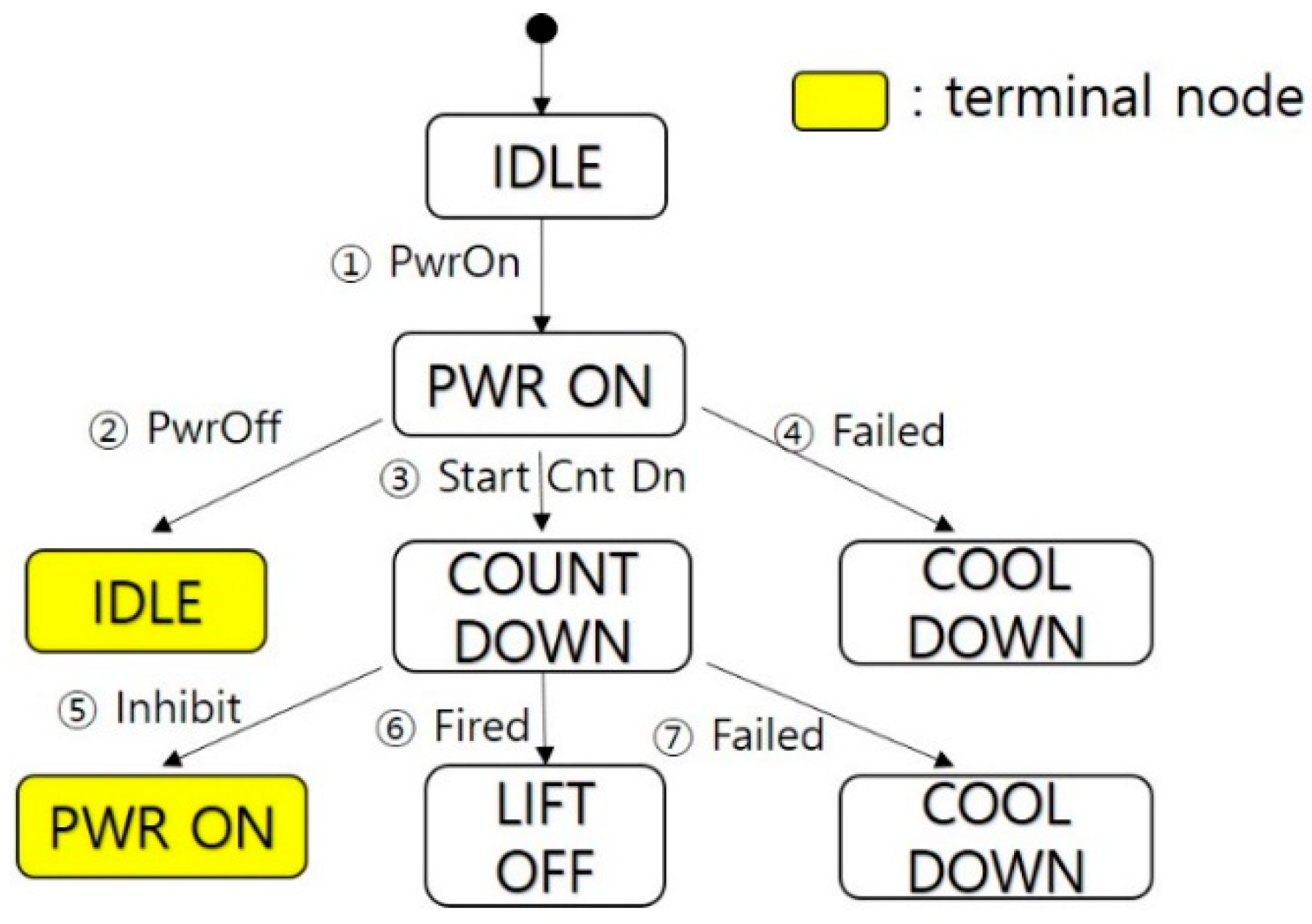
Here, we briefly describe the construction of an FSM from a specification and the generation of a test suite using the W method. For an equipment with the following requirement specification, the corresponding FSM is illustrated in Figure 2.
  • Req 1: Power Control, Power on, and off control
  • Req 2: Countdown Control, Countdown start, and lift-off detection
  • Req 3: Cool Down, Emergency cool down sequence
  • Req 4: Ready Monitoring, Take-off ready status monitoring
  • Req 5: Countdown Monitoring, Countdown status
This FSM consists of six inputs, I = {Pwr On, Pwr Off, Start Cnt Dn, Inhibit, Fired, Failed}, and five states, S = {IDLE, PWR ON, COUNT DOWN, LIFTOFF, COOLDOWN}.
From the above FSM, the W method derives a tree “T” via breadth-first search or depth-first search as follows:
  • Set the root of “T” with the initial state of the FSM, “IDLE”. This is level 1 of “T”.
  • Suppose we have already built “T” to a level “k”. The “(k + 1)”th level is built by examining nodes transferable from the “k”th-level nodes. A node at the “k”th level is terminated if it is the same as a non-terminal at some level “j”, j ≤ k. Otherwise, we attach a successor node to the “k”th-level node.
In the process of making a tree in Figure 3, if one state was already visited or a final state was encountered, the state will be a terminal node.
Five test sequences in Table 1 can be generated from the tree.

3. Proposed Method

In this section, we propose a modified method to supplement the W method. Moreover, we theoretically analyze the testing time of the two methods to determine the feasibility of the proposed method in real testing.
The terminologies used in this paper are defined as follows.
  • Node: It is used as the corresponding expression of the “state” in the tree, i.e., a “node” is used in the tree as a “state” is used in the FSM.
  • Terminal node: This is present in W method. If one state has already been visited, the state becomes a “terminal node”. The final state is also a “terminal node”.
  • Initial entry status: This is the status of the state when it has been entered for the first time.
  • Re-entry status: This is the status of the state when it is re-entered after entering another state.
  • Post-processing: This is the processing that makes the re-entry status equal to the initial entry status.
  • Post-processing error(s): These error(s) are occurred by the reasons why post-processing is incorrect.
  • Test case: This has the same meaning as “test sequence”.
  • Test set: This is the collection of test cases (sequences). It has the same meaning as “test suite”.

3.1. Algorithm

The W method ceases to make a test sequence when it encounters a previously visited state. This mechanism fails to detect post-processing errors in the IUT. To illustrate, given a state A, let Ai be the initial entry status of A and Ar be the re-entry status of A. When a software is implemented, there are many cases in which Ai is not equal to Ar. This is because of the mistakes in post-processing such as memory allocation faults and faults for initializing variables. The mechanism of the W method does not test this point, which means that it fails to check the equivalence between an FSM specification and an IUT.
Based on the foregoing, we propose a modified method to improve the W method. The proposed method adds test paths from a terminal node to a specified final state. The added paths check whether the behavior of the software is the same in the initial entry and the re-entry, i.e., the deficiency of the W method. The algorithm of the proposed method is presented below.
/// Algorithm of the proposed method ///
1: input:
2: SM: state machine, s’: a specified final state
3: output:
4: TS: Test set
5: begin
6: TS = {}, Tree Tr = {init node n0, node set N = {n0}, edge set E = {}}
7: n0 is a node corresponding to the initial state s0SM
8: for each non-terminal leaf node nTr
9:  begin
10:  for each outbound transition t of the state corresponding to n
11:   begin
12:   st = a target state of t
13:   for each input iIt
14:    begin
15:    n’ = a node corresponding to st, N = N ∪ {n’}
16:    e = an edge {n ⨯ { i } → Otn’}, E = E ∪ {e}
17:   end for
18:   if st is already represented by another node then
19:    Tr = Tr ∪ shortest path from the node n’ corresponding to st to a     node
corresponding to s’, st = s’
20:   end if
21:   if st is a final state then
22:    set n’ is terminal node
23:   end if
24:  end for
25: end for
26: for each event sequence TC from n0Tr to a terminal node nTr
27: begin
28: TS = TSTC
29: end for
///end ///
In the above algorithm, lines 6 and 7 initialize the test set and the tree. The tree, Tr, consists of the root(init) node “n0”, node set “N” corresponding to the state, and edge set “E” corresponding to the transition.
Lines 8 to 25 are the main body of the algorithm. Among these, lines 10 to 24 add child nodes and edges for transitions. Lines 18 to 20 are the novel addition which enhances the algorithm. These lines add the shortest path from the terminal node in the W method to the specified final state. Lines 21 to 23 set the node as the terminal node in the proposed method if the added child node corresponds to a specified final node. Lines 26 to 29 collect all the sequences from the initial node to the terminal node in the proposed method and make a test set (suite).
Using the new algorithm, Figure 3 becomes the tree in Figure 4.
The modified test sequences are shown in Table 2.

3.2. Testing Time Analysis

The proposed method returns a longer test suite (sequences) than the W method. To compare the testing time of the two methods, theoretical analysis is performed.
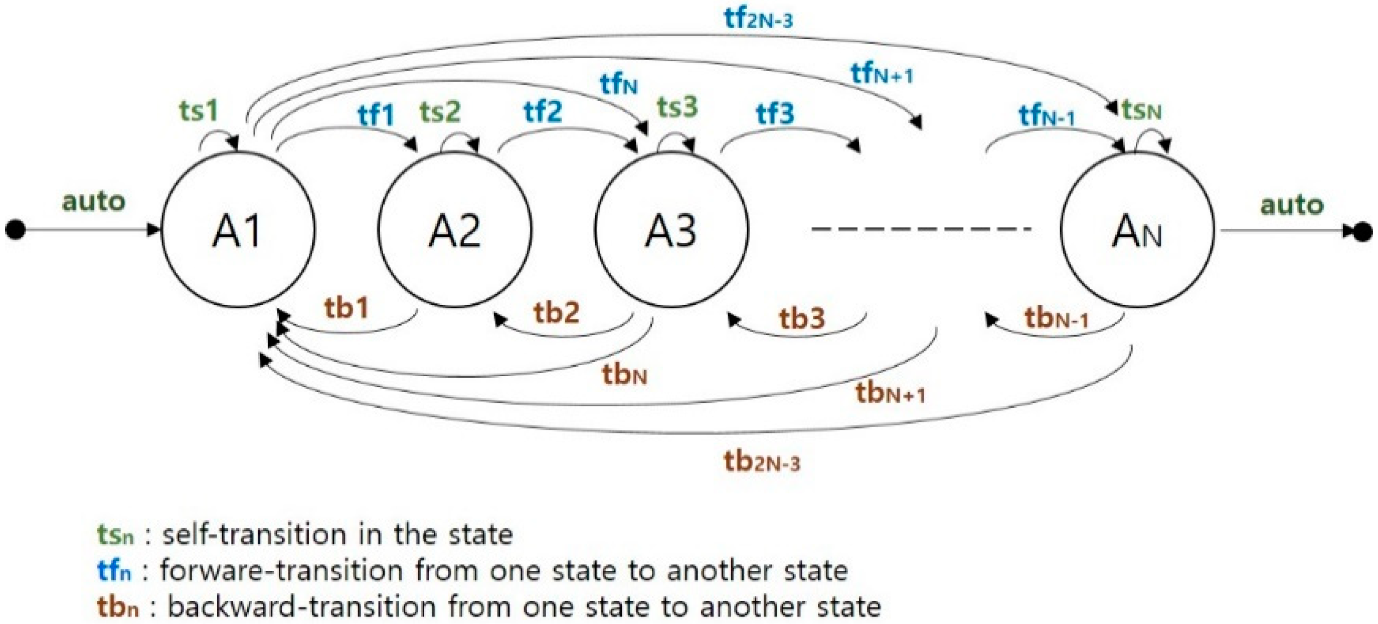
Suppose we have an FSM as in Figure 5.
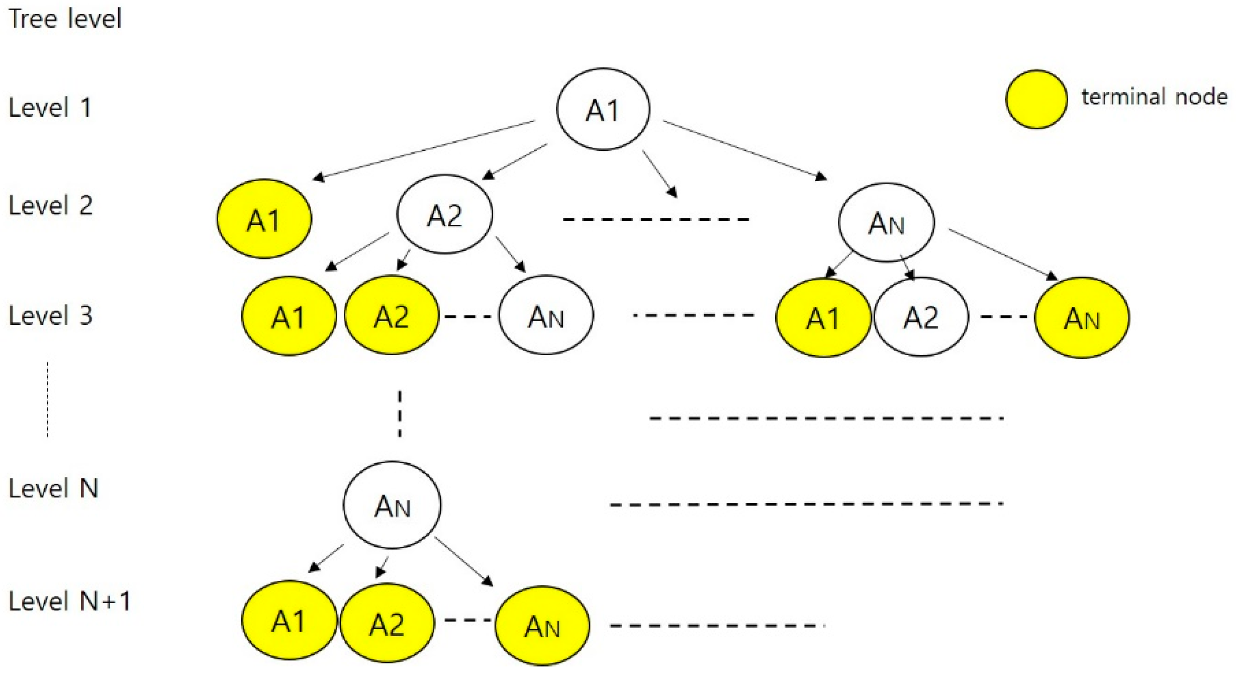
The tree derived using W method is illustrated in Figure 6.
In Figure 6, each state is denoted as “An” where “n” is varied from 1 to N. The level of the tree is denoted as “l” and is varied from 1 to N + 1.
To determine the testing time, we sum the tested nodes. In W method, the number of tested nodes, Tw, is given by the following equation.
Tw = 0 × 1 + 1 × 2 + 2 ( N 1 ) × 3 + 3 ( N 1 ) ( N 2 ) × 4 + + ( l 1 ) ( N 1 ) ! / ( N ( l 1 ) ) ! × l = l = 2 N + 1 l ( l 1 ) ( N 1 ) ! / ( N l + 1 ) !
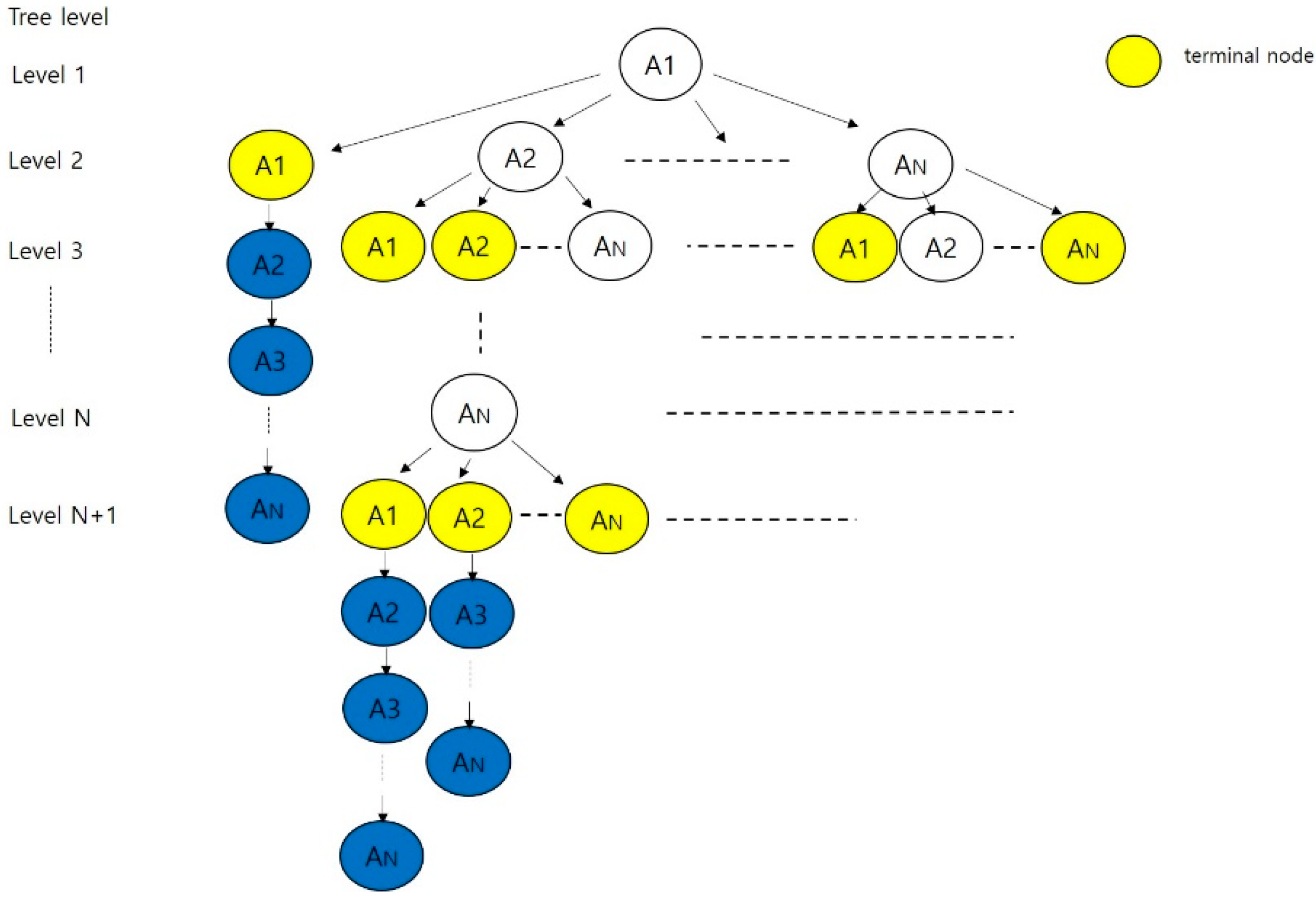
The tree derived using the proposed method is shown in Figure 7.
In the proposed method, testing time is calculated using a different approach.
In case of “An” terminal nodes:
  • The number of test nodes for a “An” in each level, Tpn(An, l), is the sum of the test nodes in W method and the added nodes in the proposed method.
  • If the number of “An”s in each level is Nt(An, l), the number of test nodes for “An”s in each level, Tpn(An, l), is Tpn(An, l) × Nt(An, l),.
  • The number of test nodes for “An”s in the tree, Tp(An), is the sum of Tp(An, l) where l is from 1 to N + 1.
As a result, the testing time of the proposed method, Tp, is the sum of Tp(An) and is given by the following equation.
T p = n = 1 N T p ( A n )
To obtain Tp(An) from Figure 7, we start with “A1” terminal nodes as follows.
  • Level 1: Tpn(A1, 1) = 1, Nt(A1, 1) = 0, Tp(A1,1) = 0
  • Level 2: Tpn(A1, 2) = N + 1, Nt(A1, 2) = 1, Tp(A1,2) = N + 1
  • Level 3: Tpn(A1, 3) = N + 2, Nt(A1, 3) = N − 1, Tp(A1,3) = (N + 2) × (N − 1)
  • Level 4: Tpn(A1, 4) = N + 3, Nt(A1, 4) = (N − 1)(N − 2), Tp(A1,4) = (N + 3) × (N − 1)(N − 2)
……
5.
Level N + 1: Tpn(A1, N + 1) = 2N, Nt(A1, N + 1) = (N − 1)!), Tp(A1,N + 1) = 2N × (N − 1)!
According to the above results,
T p ( A 1 ) = l = 2 N + 1 ( N + l 1 ) ( N 1 ) ! / ( N l + 1 ) !
In the same manner,
T p ( A 2 ) = l = 2 N + 1 ( N + l 2 ) ( l 2 ) ( N 2 ) ! / ( N l + 1 ) !
T p ( A N ) = l = 2 N + 1 l ( l 2 ) ( N 2 ) ! / ( N l + 1 ) !
Therefore,
T p = n = 1 N T p ( A n ) = l = 2 N + 1 [ { ( N 1 ) ! ( 2 l 2 + ( N 4 ) l + 2 ) } / 2 ( N l + 1 ) ! ]  
Using Equations (1) and (6), we get the following results in Table 3 and Figure 8.
From the above, we know that the proposed method takes about 1.4 times longer than the W method. Nevertheless, the proposed method remains acceptable considering the enhanced effectiveness of the testing, especially in the safety-critical system.

4. Case Study

Four case studies are performed with the software of the safety-critical system. These are console software of the army missile defense system, a console software of the navy missile defense system, a satellite operation software, and a radar operation software. Among these, only the first case study is described in detail. The other case studies are briefly summarized.

4.1. Methodology

Case studies were performed through the following methodology.
  • Construct an FSM specification from the requirement specification.
  • Derive a tree and generate test suites using the W method and the proposed method.
  • Test the implementation of the two test suites and compare the results. This step is repeated to check the reproducibility of the test.
The basic information of the case studies is shown in Table 4.

4.2. Constructing FSM

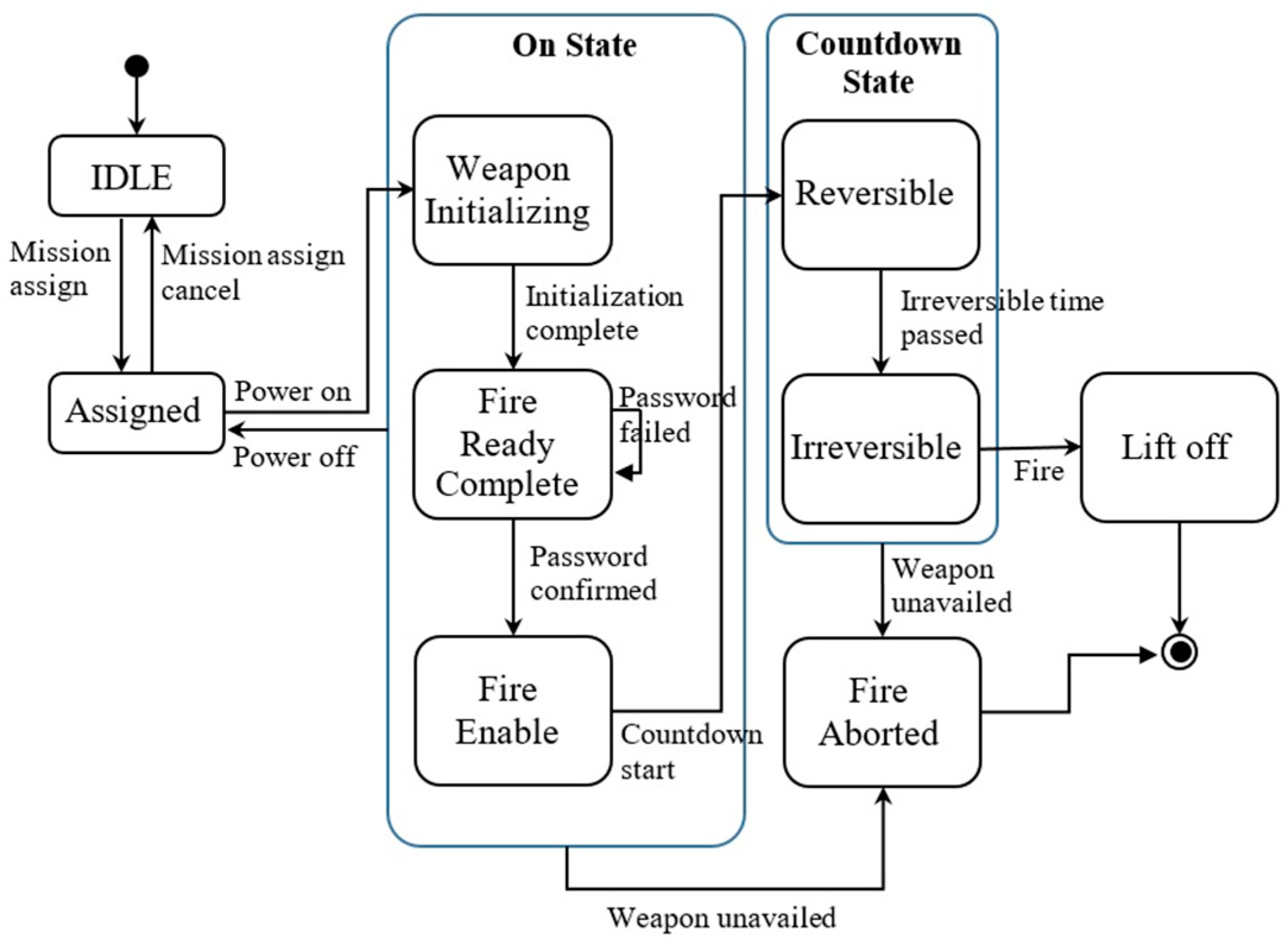
In this section, we show the FSM specification from the requirements specification. The requirements of the army missile console software are as follows.
  • Req 1: Mission Assign, Mission assignment, or cancel
  • Req 2: Password Control, Input password, and confirm
  • Req 3: Power Control, Power on, and off control
  • Req 4: Mission Process Control, Mission Processing after Power on
  • Req 5: Countdown Control, Countdown start, and lift-off detection
  • Req 6: Fire Aborted (Cool down), Emergency cool down sequence execution
  • Req 7: Ready Monitoring, Firing Ready status monitoring
  • Req 8: Countdown Monitoring, Countdown status monitoring
The constructed FSM is shown in Figure 9.

4.3. Deriving Tree and Generating Test Suite

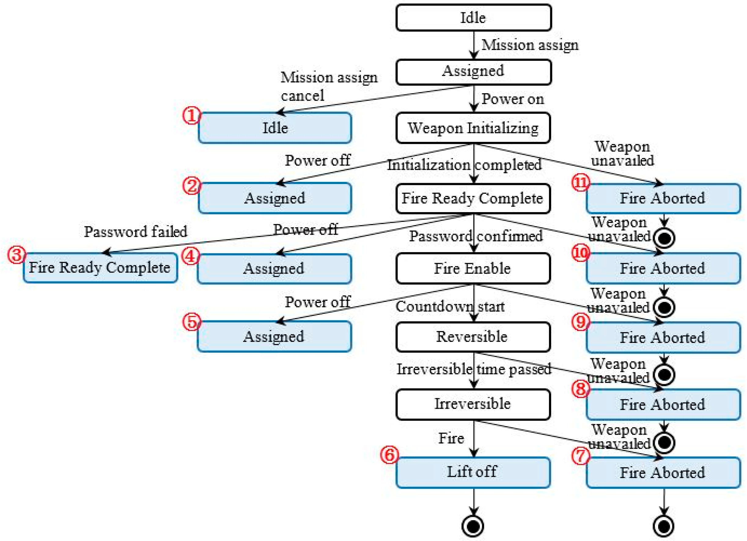
Two trees were derived from the above FSM. Figure 10 shows the tree using W method.
Figure 11 shows the tree using the proposed method.
Two test suites were generated from the above trees as shown in Table 5 and Table 6.
Table 7 shows the requirements covered by the two test suites.

4.4. Test and Results

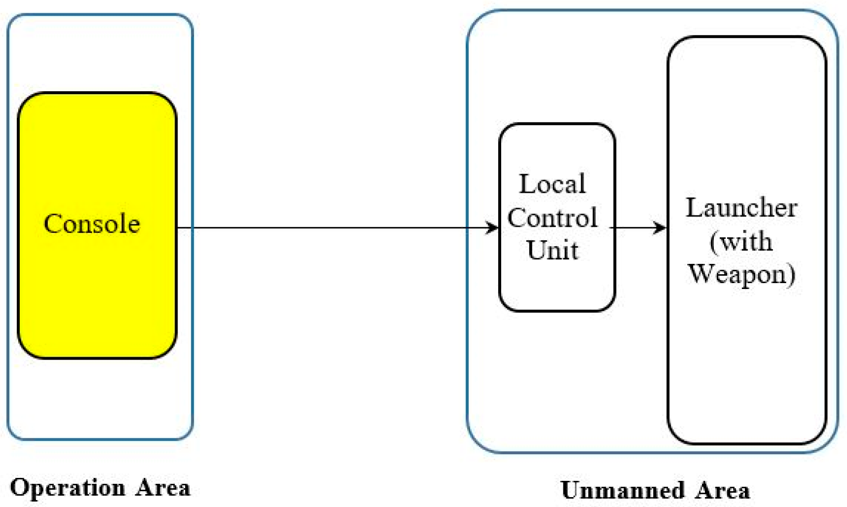
The configuration of the missile defense system is shown in Figure 12, which was used as the test configuration. The equipment used for testing were the real equipment, except for the launcher (with weapon), which was substituted with a simulator. While the test was processed, we checked the results through the graphic user interface(GUI) screen of the console.
The test results from the two suites are shown in Table 8.
The proposed method detected two errors more than that of the W method.
One error was detected in test sequence no. 1 [Idle → Assigned → Idle → Assigned → …]. The original sequence of W method is [Idle → Assigned → Idle]. The error is that the weapon (missile) was not assigned in the re-entry to the “Assigned” state. In the initial entry, missile assignment was performed successfully, but in the re-entry after cancelling the assignment, missile reassignment failed. This error is a fatal error resulting in the mission not being performed.
The other error was detected in test sequences no. 5 […→Assigned→…→Fire Enable→Assigned→ …→Fire Enable→…→Lift off]. The original sequence of W method is […→Assigned→Weapon Initializing→Fire Ready Complete→ …]. The error is that the firing authority was permitted without checking for a password. In the initial entry to the “Fire Enable” state, password checking was performed successfully, but in the re-entry, the firing authority was given without checking for a password. This error is also a fatal error in that a missile can be fired by a person who does not have the authority. These errors appeared repeatedly when the same software is used without debugging the errors.
This case study indicates that our proposed method can more properly check the equivalence between the FSM specification and the IUT.
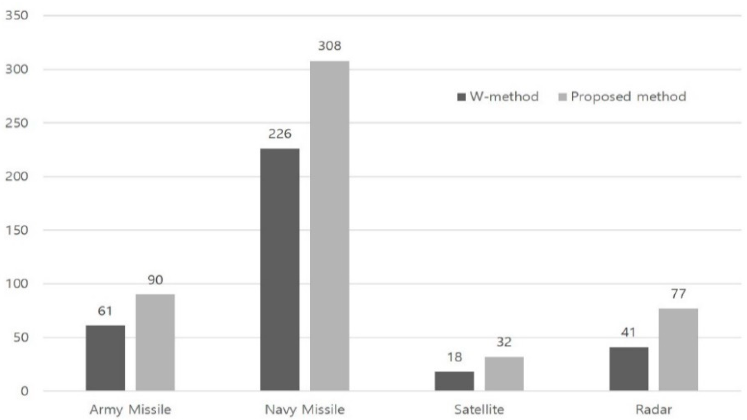
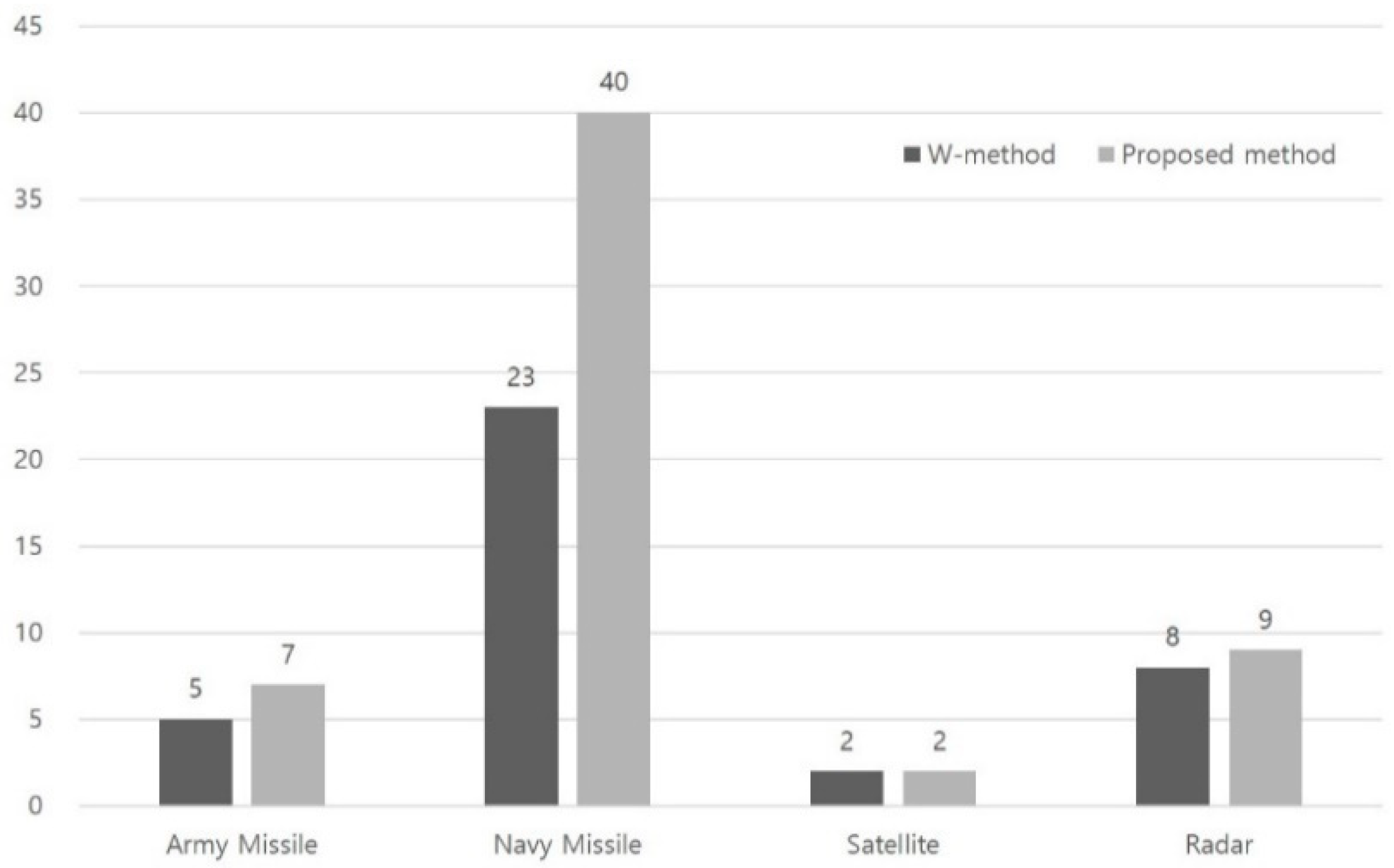
Other case studies were performed in the same manner. The test summary is shown in Table 9, Figure 13 and Figure 14.
From Table 4 and Table 9, we observed that the difference in the number of errors found by the two methods increases as the software becomes longer and more complex. This means that there are more post-processing errors, and our method becomes a better option for testing as the software becomes longer and more complex.

5. Conclusions

Testing is the most important part of software development, especially in safety-critical systems. Among numerous testing methods, FSM and the W method have been widely used.
However, the W method fails to detect post-processing errors in the IUT. To correct this deficiency, we proposed an enhanced fault-detection W method to generate test suites (sequences), analyzed the testing time, and applied the method to case studies. Through testing time analysis and case studies, we demonstrated that system checking through the W method is not up to par with our method, even if our method is time consuming. This indicates that the consistency between design and implementation can be verified explicitly by using our method. Furthermore, our method is more appropriate than the W method for software testing in safety-critical systems where the error-free characteristic is more important than anything else.
Moreover, we showed that the difference in the number of errors captured by the two methods increases as the software becomes larger and more complex. This result inferred that our method is a better option for testing larger software. Thus, our method can be used to increase software reliability in safety-critical embedded systems.
In future studies, the proposed method will be applied to more case studies for further modification and generalization.

Author Contributions

Conceptualization, B.K. and J.B.; methodology, B.K.; software, S.K. and K.P.; validation, B.K. and J.B.; formal analysis, B.K.; investigation, J.B.; writing—original draft preparation, B.K.; writing—review and editing, H.K. All authors have read and agreed to the published version of the manuscript.

Funding

This research received no external funding.

Conflicts of Interest

The authors declare no conflict of interest.

References

  1. Lee, D.; Yannakakis, M. Principles and Methods of Testing Finite State Machines―A survey. Proc. IEEE 1996, 84, 1090–1123. [Google Scholar] [CrossRef] [Green Version]
  2. Chow, T.S. Testing software design modeled by finite-state machines. IEEE Trans. Softw. Eng. 1978, 4, 178–187. [Google Scholar] [CrossRef]
  3. Dorofeeva, M.; Koufareva, I. Novel modification of the W-method. Jt. NCC IIS Bull. Comp. Sci. 2002, 18, 69–80. [Google Scholar]
  4. Fujiwara, S.; Bochmann, G.; Khendek, F.; Amalou, M.; Ghedamsi, A. Test selection based on finite state models. IEEE Trans. Softw. Eng. 1991, 6, 591–603. [Google Scholar] [CrossRef]
  5. Petrenko, A.; Yevtushenko, N.; Bochmann, G.V. Testing deterministic implementations from their nondeterministic specifications. In Proceedings of the Testing of Communicating Systems: Proceedings IFIP 9th Intern Workshop of Protocol Test Systems, Darmstadt, Germany, 9–11 September 1996. [Google Scholar]
  6. Cutigi, J.F.; Simao, A.; Souza, S.R.S. Reducing FSM-Based Test Suites with Guaranteed Fault Coverage. Comput. J. 2016, 5, 1129–1143. [Google Scholar] [CrossRef]
  7. Florentin, I.; Logica, B. W-method for Hierarchical and Communicating Finite State Machines. In Proceedings of the 2007 5th IEEE International Conference on Industrial Informatics, Vienna, Austria, 23–27 June 2007. [Google Scholar]
  8. Liang, H.; Dingel, J.; Diskin, Z. A Comparative Survey of Scenario-Based to State-Based Model Synthesis Approaches. In Proceedings of the International Workshop on Scenarios and State Machines: Models, Algorithms, and Tools, Shanghai, China, 27 May 2006. [Google Scholar]
  9. Whittle, J.; Schumann, J. Generating Statechart Designs from Scenarios. In Proceedings of the International Conference on Software Engineering, Limerick, Ireland, 4–11 June 2000. [Google Scholar]
  10. Sun, J.; Dong, J.S. Extracting FSMs from Object-Z Specifications with History Invariants. In Proceedings of the International Conference on Engineering of Complex Computer Systems, Shanghai, China, 16–20 June 2005. [Google Scholar]
  11. Dick, J.; Faivre, A. Automating the Generation and Sequencing of Test Cases from Model Based Specifications. In Proceedings of the FME’93: Industrial-Strength Formal Methods, Fifth International Symposium Formal Methods Europe, Odense, Denmark, 19–23 April 1993. [Google Scholar]
  12. Carrington, D.; MacColl, I.; McDonald, J.; Murray, L.; Strooper, P. From Object-Z Specifications to ClassBench Test Suites. Softw. Test. Verif. Reliab. 2000, 10, 111–137. [Google Scholar] [CrossRef] [Green Version]
  13. Hierons, R.M. Testing from a Z Specification. Softw. Test. Verif. Reliab. 1997, 7, 19–33. [Google Scholar] [CrossRef]
  14. Weißleder, S. Simulated Satisfaction of Coverage Criteria on UML State Machines. In Proceedings of the IEEE International Conference on Software Testing, Verification and Validation, Paris, France, 6–9 April 2010. [Google Scholar]
  15. Friske, M.; Schelingloff, B.H. Improving Test Coverage for UML State Machines using Transition Instrumentation. In Proceedings of the International Conference on Computer Safety, Reliability, and Security, Nuremberg, Germany, 18–21 September 2007; pp. 301–314. [Google Scholar]
  16. Rajan, A.; Whalen, M.W.; Heimdahl, M.P.E. The Effect of Proagram and Model Structure on MC/DC Test Adequacy Coverage. In Proceedings of the International Conference on Software Engineering, Leipzig, Germany, 10–18 May 2008. [Google Scholar]
  17. Aleksandr, S.T.; Maxim, L.G.; Nina, V.Y. Testing systems of Interacting Timed Finite State Machines with the Guaranteed Fault Coverage. In Proceedings of the 17th International Conference of Young Specialists on Micro/Nanotechnologies and Electron Devices(EDM), Erlagol, Russia, 30 June–4 July 2016. [Google Scholar]
  18. Hoda, K. Finite State Machine Testing Complete Round-trip Versus Transition Trees. In Proceedings of the IEEE 28th International Symposium on Software Reliability Engineering Workshops, Toulouse, France, 23–26 October 2017. [Google Scholar]
  19. Booch, G.; Rumbaugh, J.; Jacobson, I. Unified Modelling Language User Guide, 2nd ed.; Addison-Wesley Longman Publishing Co., Inc.: Boston, MA, USA, 2005. [Google Scholar]
  20. UML. Available online: http://www.omg.org/spec/UML (accessed on 18 December 2019).
  21. Harel, D.; Politi, M. Modeling Reactive Systems with Statecharts: The STATEMATE Approach; McGraw-Hill: New York, NY, USA, 1998. [Google Scholar]
  22. ITU-T. Recommendation Z.100 Specification and Description Language (SDL).; International Telecommunications Union: Geneva, Switzerland, 1999. [Google Scholar]
Figure 1. An example of state machine.
Electronics 09 00797 g001
Figure 2. State machine of a sample system.
Electronics 09 00797 g002
Figure 3. Tree of the sample system by W method.
Electronics 09 00797 g003
Figure 4. Tree of the sample system using the proposed method.
Electronics 09 00797 g004
Figure 5. Sample FSM for testing time analysis.
Electronics 09 00797 g005
Figure 6. Tree using W method.
Electronics 09 00797 g006
Figure 7. Tree using the proposed method.
Electronics 09 00797 g007
Figure 8. Testing time of two methods and testing time increasing rate of Tp by number of states.
Electronics 09 00797 g008
Figure 9. FSM of the army missile console software.
Electronics 09 00797 g009
Figure 10. Tree derived using W method.
Electronics 09 00797 g010
Figure 11. Tree derived using the propose method.
Electronics 09 00797 g011
Figure 12. Configuration of the army missile defense system.
Electronics 09 00797 g012
Figure 13. Total testing Length of case studies.
Electronics 09 00797 g013
Figure 14. No. of Errors of case studies.
Electronics 09 00797 g014
Table 1. Test suite by W method.
No. of
Test Sequence
Test SequenceCovered
Requirements
1Idle → Pwr on →IdleReq. 1, 4
2Idle → Pwr on →Count down→Pwr onReq. 2, 5
3Idle → Pwr on →Count down→Lift offReq. 2, 3, 5
4Idle → Pwr on →Cool downReq. 1, 4
5Idle → Pwr on →Count down→Cool downReq. 2, 3, 5
Table 2. Test suite by the proposed method.
No. of
Test Sequence
Test SequenceCovered
Requirements
1Idle → Pwr on →Idle→ Pwr on →Count down→
Lift off
Req. 1, 2, 3, 4, 5
2Idle → Pwr on →Count down→Pwr on→
Count down→Lift off
Req. 1, 2, 3, 4, 5
3Idle → Pwr on →Count down→Lift offReq. 2, 3, 5
4Idle → Pwr on →Cool downReq. 1, 4
5Idle → Pwr on →Count down→Cool downReq. 2, 3, 5
Table 3. Results of Tw and Tp.
No. of States (N)TwTpTp/Tw
338511.34
42122931.38
5137019241.40
610,11214,3521.42
784,158120,3651.43
8780,9081,123,4111.44
98,000,88211,562,9181.44
Table 4. Software information of the case studies.
Army MissileNavy MissileSatelliteRadar
No. of Modules997268492774
Lines of Code74,122220,153520760,389
McCabe’s Cyclomatic Complexity788125,7015126358
Table 5. Test suite using W method.
No. of
Test Sequence
Test Sequence
1Idle→Assigned→Idle
2Idle→Assigned→Weapon Initializing → Assigned
3Idle→Assigned→Weapon Initializing →Fire Ready Complete→ Fire Ready Complete
4Idle→Assigned→Weapon Initializing →Fire Ready Complete→ Assigned
5Idle→Assigned→Weapon Initializing →Fire Ready Complete→ Fire Enable→
Assigned
6Idle→Assigned→Weapon Initializing →Fire Ready Complete→ Fire Enable →
Reversible→ Irreversible→Lift off
7Idle→Assigned→Weapon Initializing →Fire Ready Complete→ Fire Enable →
Reversible→ Irreversible→Fire Aborted
8Idle→Assigned→Weapon Initializing →Fire Ready Complete→ Fire Enable →
Reversible→ Fire Aborted
9Idle→Assigned→Weapon Initializing →Fire Ready Complete→ Fire Enable →
Fire Aborted
10Idle→Assigned→Weapon Initializing →Fire Ready Complete→ Fire Aborted
11Idle→Assigned→Weapon Initializing → Fire Aborted
Table 6. Test suite using the proposed method.
No. of
Test Sequence
Test Sequence
1Idle→Assigned→Idle→Assigned→Weapon Initializing →Fire Ready Complete→
Fire Enable →Reversible→ Irreversible→Lift off
2Idle→Assigned→Weapon Initializing → Assigned→Weapon Initializing →Fire Ready Complete→Fire Enable →Reversible→ Irreversible→Lift off
3Idle→Assigned→Weapon Initializing →Fire Ready Complete→ Fire Ready Complete
→Fire Enable →Reversible→ Irreversible→Lift off
4Idle→Assigned→Weapon Initializing →Fire Ready Complete→ Assigned→Weapon Initializing →Fire Ready Complete→Fire Enable →Reversible→ Irreversible→Lift off
5Idle→Assigned→Weapon Initializing →Fire Ready Complete→ Fire Enable→
Assigned→Weapon Initializing→Fire Ready Complete→Fire Enable →Reversible→ Irreversible→Lift off
6Idle→Assigned→Weapon Initializing →Fire Ready Complete→ Fire Enable →
Reversible→ Irreversible→Lift off
7Idle→Assigned→Weapon Initializing →Fire Ready Complete→ Fire Enable →
Reversible→ Irreversible→Fire Aborted
8Idle→Assigned→Weapon Initializing →Fire Ready Complete→ Fire Enable →
Reversible→ Fire Aborted
9Idle→Assigned→Weapon Initializing →Fire Ready Complete→ Fire Enable →
Fire Aborted
10Idle→Assigned→Weapon Initializing →Fire Ready Complete→ Fire Aborted
11Idle→Assigned→Weapon Initializing → Fire Aborted
Table 7. Covered Requirements.
No. of
Test Sequence
W MethodProposed Method
1Req. 1Req. 1, 2, 3, 4, 5, 6, 7, 8
2Req. 1, 3, 4Req. 1, 2, 3, 4, 5, 6, 7, 8
3Req. 1, 2, 3, 4, 7Req. 1, 2, 3, 4, 5, 6, 7, 8
4Req. 1, 3, 4, 7Req. 1, 2, 3, 4, 5, 6, 7, 8
5Req. 1, 2, 3, 4, 7Req. 1, 2, 3, 4, 5, 6, 7, 8
6Req. 1, 2, 3, 4, 5, 7, 8Req. 1, 2, 3, 4, 5, 7, 8
7Req. 1, 2, 3, 4, 5, 6, 7, 8Req. 1, 2, 3, 4, 5, 6, 7, 8
8Req. 1, 2, 3, 4, 5, 6, 7, 8Req. 1, 2, 3, 4, 5, 6, 7, 8
9Req. 1, 2, 3, 4, 6, 7Req. 1, 2, 3, 4, 6, 7
10Req. 1, 3, 4, 6, 7Req. 1, 3, 4, 6, 7
11Req. 1, 3, 4, 6Req. 1, 3, 4, 6
Table 8. Test results.
Test SuiteTotal Length
(Test Nodes)
No. of Errors
(Founded)
W method615
Proposed method907
Table 9. Results of case studies.
Case Study No.SystemTotal Testing Length
(W/Proposed)
No. of Errors
(W/Proposed)
1Army Missile61/905/7
2Navy Missile226/30823/40
3Satellite18/322/2
4Radar41/778/9