Review

A Survey on LiDAR Scanning Mechanisms

Department of Electrical, Electronic and Systems Engineering, Faculty of Engineering and Built Environment, The National University of Malaysia, Bangi, Selangor 43600, Malaysia
*
Authors to whom correspondence should be addressed.
Electronics 2020, 9(5), 741; https://doi.org/10.3390/electronics9050741
Submission received: 30 March 2020 / Revised: 14 April 2020 / Accepted: 22 April 2020 / Published: 30 April 2020
(This article belongs to the Section Microwave and Wireless Communications)

Abstract

:
In recent years, light detection and ranging (LiDAR) technology has gained huge popularity in various applications such as navigation, robotics, remote sensing, and advanced driving assistance systems (ADAS). This popularity is mainly due to the improvements in LiDAR performance in terms of range detection, accuracy, power consumption, as well as physical features such as dimension and weight. Although a number of literatures on LiDAR technology have been published earlier, not many has been reported on the state-of-the-art LiDAR scanning mechanisms. The aim of this article is to review the scanning mechanisms employed in LiDAR technology from past research works to the current commercial products. The review highlights four commonly used mechanisms in LiDAR systems: Opto-mechanical, electromechanical, micro-electromechanical systems (MEMS), and solid-state scanning. The study reveals that electro-mechanical scanning is the most prominent technology in use today. The commercially available 1D time of flight (TOF) LiDAR instrument is currently the most attractive option for conversion from 1D to 3D LiDAR system, provided that low scanning rate is not an issue. As for applications with low size, weight, and power (SWaP) requirements, MEMS scanning is found to be the better alternative. MEMS scanning is by far the more matured technology compared to solid-state scanning and is currently given great emphasis to increase its robustness for fulfilling the requirements of ADAS applications. Finally, solid-state LiDAR systems are expected to fill in the gap in ADAS applications despite the low technology readiness in comparison to MEMS scanners. However, since solid-state scanning is believed to have superior robustness, field of view (FOV), and scanning rate potential, great efforts are given by both academics and industries to further develop this technology.

1. Introduction

In recent years, light detection and ranging (LiDAR) technology has been deployed in a myriad of applications. Over the years, the LiDAR system design has improved considerably, resulting in a design with remarkably low cost, size, weight, and power (SWaP) requirements. Being light and energy saving, the role of LiDAR in aerial and mobile platforms has increased to facilitate mapping and obstacle avoidance which were traditionally thought to be challenging. As stated by Liner. J, “A lean system is more desirable in the current social, economic, political, and global environments” [1].
The classification of LiDAR instruments can be broad and subjective, depending upon the context of application. Nonetheless, this instrument is commonly classified using the three types of information-capturing functionality it offers namely spatial, spectral, and temporal. Spatial information-capturing is a fundamental functionality of every LiDAR instrument. This information is typically obtained using the time of flight (TOF) measurement. LiDAR systems that are able to gather spatial information are available in three varieties: one-dimensional (1D), two-dimensional (2D), three-dimensional (3D), with the 2D and 3D spatial information gathering achieved with the aid of optical deflecting systems. The spatial information is essential for constructing an accurate 3D map of the environment. However, spatial information alone is not sufficient for application requiring object detection. The second class of LiDAR instruments are capable of measuring the spectral information of a material such as the laser return intensity (LRI). LRI refers to the reflectance because of the interaction between the wavelength of the transmitted pulse from the LiDAR instrument and the targeted material. Since the LRI is characteristic to a specific material type, it is potentially useful for identification of surface properties of a target material. However, to avoid ambiguities in LRI readings, at least two wavelengths of laser are required. On top of that, some application requires temporal information gathering functionality in addition to spatial and spectral information. This can be achieved by using the repeated LiDAR technique. Repeated LiDAR is a process of collecting temporal data of a target environment over a finite period of time [2]. Temporal information is essential for understanding dynamic processes such as plant growth and soil erosion [3].
Numerous reviews on LiDAR technologies geared toward specific applications have been published in the past [3,4,5], ([6], p. 3), [7,8,9,10,11,12]. It was observed that the major portion of the literature is dedicated for theoretical analysis of LiDAR principle [4,5,6,7]. The understanding of LiDAR principle helps the designer to select an appropriate technique for his application of interest. Besides that, conceptual frameworks were introduced in the past to describe the LiDAR architectures. The LiDAR instrument is a composition of multiple subsystems such as power supply, range finding, control, and beam deflection. As mentioned earlier, the low SWaP specifications have significantly influenced the improvement of selected subsystems, especially the power supply and range finding. This serves as a guideline for the design and development of LiDAR systems at the component level.
Albeit the number of review articles published in the past, there is still a lack of review articles dedicated specifically to the scanning mechanisms of LiDAR instruments. Consequently, the LiDAR beam scanning literature continues to expand in different focus areas without appropriate organization. Being an integral component of the 2D and 3D LiDAR architecture, the scanning mechanism is an important feature because it influences the SWaP specifications of the overall design. Furthermore, there is a need for the designer to be aware of state-of-the-arts scanning mechanisms as the trends of LiDAR instruments in the market are changing rapidly. Hence, the aim of this paper is to provide a comprehensive survey of LiDAR scanning mechanisms by reviewing past research works as well as commercial datasheets. We propose a classification scheme for various LiDAR scanning mechanisms into four main classes: (i) opto-mechanical, (ii) electro-mechanical (iii) MEMS, (IV) solid-state based. Subsequently, the performance, SWaP specifications, as well as the technology readiness level for each class has been examined critically.
The study reveals that mechanical scanning has achieved high maturity level compared to the rest. Commercially available 1D TOF LiDAR modules in combination with mechanical stages have been the preferred combination for the development of 2D or 3D LiDAR systems. Next on the list, MEMS scanning has also achieved a remarkable technological readiness level for manufacturing. It is widely considered for applications requiring low SWaP requirements.
The rest of this paper is arranged as follows. Section 2 introduces the LiDAR architecture and specifications relevant to beam scanning. In Section 3, the classification of beam deflection mechanism is presented. In Section 4, discussion on latest trends in LiDAR design is presented. Finally, there is a brief conclusion in the last section.

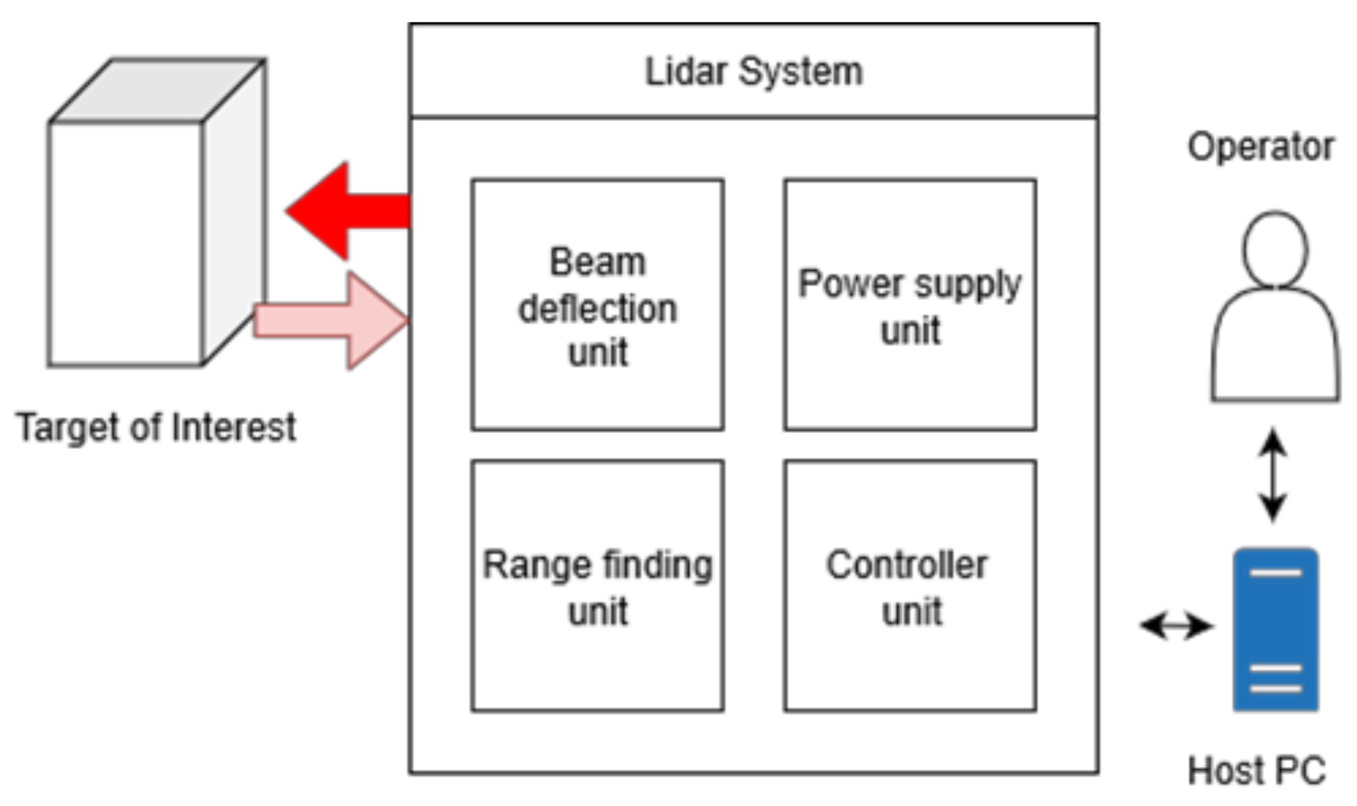
2. LiDAR Architecture Overview

The LiDAR architecture is defined as “the art of LiDAR instrumentation concerning LiDAR hardware and software” [13,14,15,16]. A fully functional LiDAR system is made of four major subsystems namely laser rangefinder, beam deflection, power management, and master controller units, as depicted in Figure 1. These basic blocks are equally mandatory whereby a failure in any of these subsystems may lead to a loss in functionality of the LiDAR system. However, in the absence of the beam deflection subsystem, the LiDAR could still function as a 1D LiDAR, which is commonly known as a laser range finder (LRF).
The range finding unit is the core of the LiDAR system, within which are present the components required to generate, transmit, and receive short laser pulses. Laser diode, photo diode, transimpedance amplifier (TIA), and time to digital converter (TDC) are the commonly found components in the range finding unit. Optical components such as collimating lens and focusing lens are also employed in the range finding units to respectively reduce the divergence of the transmitted beam, and focus the received laser beam into the detector. The control unit handles basic signal processing, control signal generation, and communication with the host PC. The final subsystem is the power supply unit, which is responsible for producing necessary power required by the LiDAR system. The design of this unit is subjective, depending upon the voltage and current requirements of the beam sub units in the LiDAR system. Typically, direct current (DC) machines such as servo motors and stepper motors consume 5 to 12 V and 1.0 A, while the microcontroller requires 3.3 V to 5 V to operate. Hence, the power supply units incorporate regulators that are capable of handling multiple voltage requirements. Finally, the beam deflection unit which is an integral part of the LiDAR system is responsible for acquiring spatial information in 2-or 3-dimensional scans. Currently, there are numerous mechanisms to implement this unit. The following section is geared toward an extensive review on the beam deflection mechanisms for a LiDAR system.

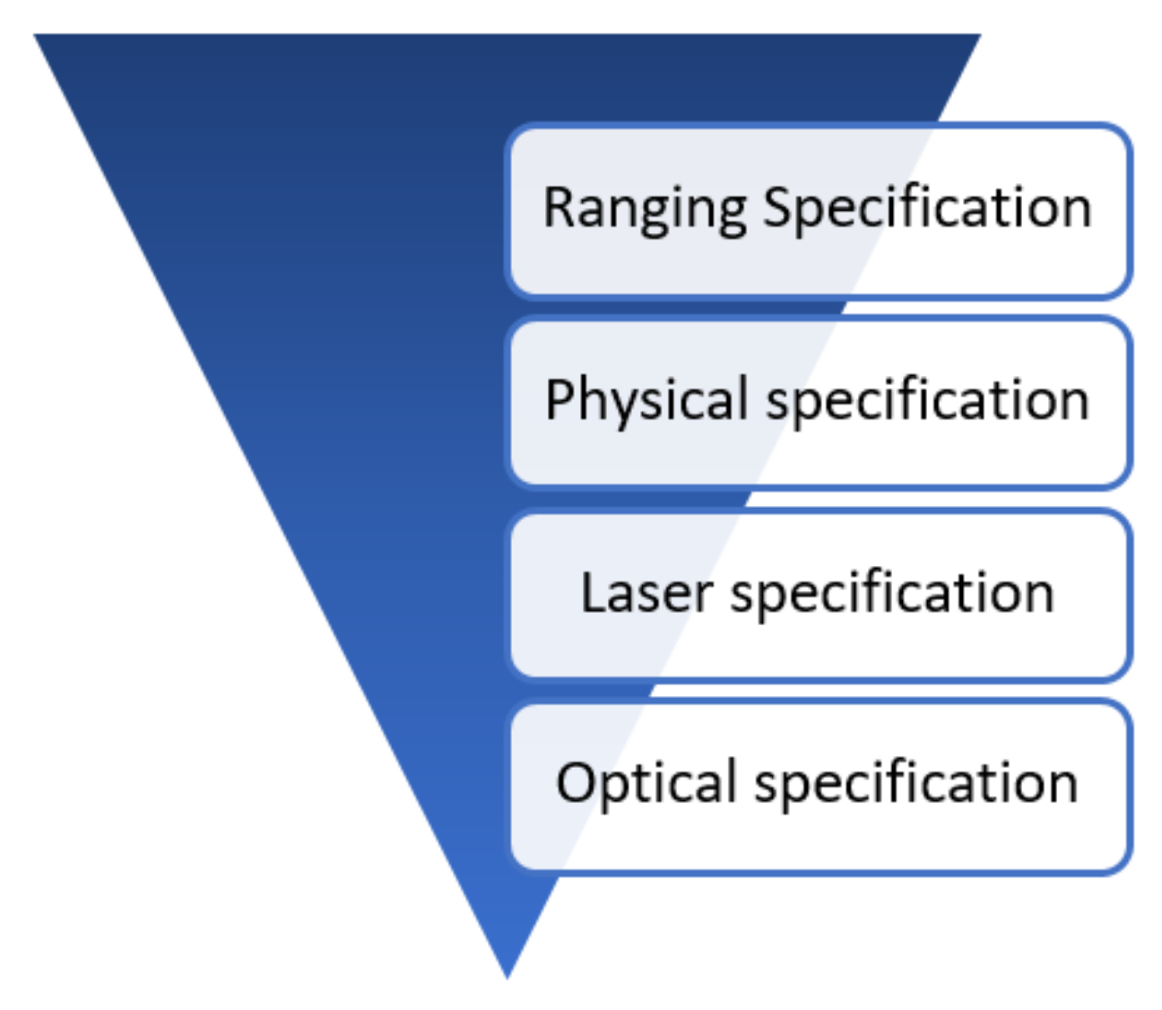
2.1. LiDAR Specifications

The LiDAR scanner specifications are essential information for a developer to select an optimal product that best suits his application. It can be broken down to four levels as depicted in Figure 2. The first specifications in the hierarchy include information related to ranging such as maximum and minimum detection range, resolution, accuracy, update frequency. Second specifications in the hierarchy are related to physical parameters such as size, weight, power consumption which can be found in a product manual. These specifications are important for applications involving mobile or aerial platforms where the size, weight, and power may be a constraint. Since LiDAR employs lasers, information related to that such as wavelength, power emitted, and class of laser is included in the specifications as a part of safety compliance. Some manufacturers even disclose specifications related to the optics of the LiDAR as shown in the bottom of Figure 2. Example of optical specifications commonly found in product manual includes focal length of lens and beam divergence. The specifications described thus far only best describes a characteristics of 1D LIDAR. In the case of scanning LiDAR additional specifications related to motion of the beam deflection is required. This specification includes parameters like field of view (FOV), angular resolution, response time (Tresp) and number of scan points (N). The details of scanner specifications are discussed in the next section.

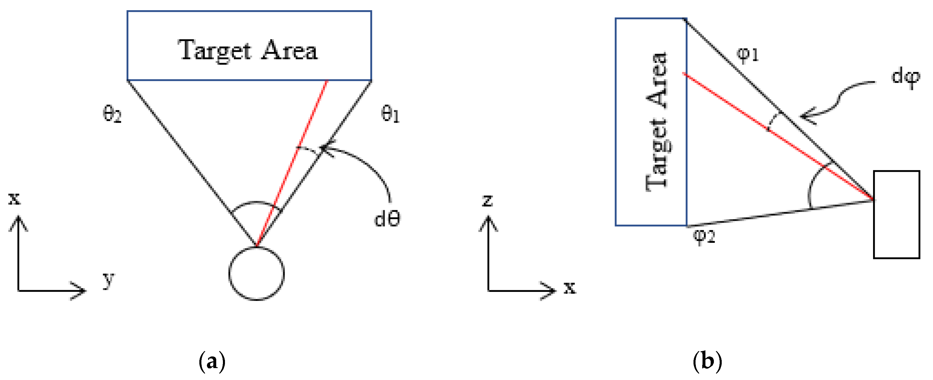
2.2. Beam Scanner Specifications

This section presents specifications related to motion of LiDAR beam. First the FOV is one of the primary specifications that falls under this list. FOV is the span of area that can be observed by a scanning LiDAR. Typically the unit for FOV is represented in degrees. For 2D LiDAR the FOV is only limited to horizontal plane, while for 3D scanner it involves both horizontal and vertical planes as depicted in Figure 3. The computation of horizontal FOV (FOVH) is shown in Equation (1). Similarly, the computation for vertical FOV (FOVV) is shown in Equation (2).
Next, angular resolution is the second most important specification of scanning LiDAR. In contrast to the range resolution, angular resolution describes the smallest possible step that can be moved in axis of rotation of the laser beam as shown in Figure 3. Based on the literature; there is no standard unit for representing angular resolution. Similar with the specifications of stepper motor, some manufacturers and researchers use degrees while others use total number of steps to represent the angular resolution. The relationship between these two units is described in Equations (3) and (4). The representation of angular resolution in terms of number of steps offer several advantages as it helps to derive further performance parameters such as line scan time (TLine), angular axis rate (A), and total number of scan points (N). The angular resolution is mainly influenced by the motor and encoder employed in the design. High resolution metal disc (4 inch) encoders are capable of providing angular resolution up to 0.072° degrees. The resolution of the encoder disc is directly proportional to its diameter. Hence, there is a tradeoff between resolution and diameter of encoder disc when a low SWaP design is desired.
Angular rate is another specification used to describe the frequency of LiDAR beam motion. For 2D LiDAR the time taken for one complete sweep in the FOVH is called the line scan time (TLine). This parameter is a product of horizontal resolution (Hres) and response time (Tresp) as shown in Equation (5). Furthermore, the angular rate for horizontal axis (AH) is computed by taking the reciprocal of line scan time (TLine) as shown in Equation (6). The unit for horizontal axis rate (AH) is measured in Hertz. Unlike the computation of horizontal axis rate, the vertical axis (AV) rate requires derivation of extra parameters before it can be computed. The total number of scan points (N) is one such parameter. It is a product of horizontal resolution (Hres) and vertical resolution (Vres) as shown in Equation (7). Later, the time taken for a complete frame (Tframe) is computed as shown in Equation (8). Lastly, the vertical axis rate (AV) is computed by taking the reciprocal of frame time (Tframe). The angular rates can be also expressed in terms of degrees per second as shown in Equation (10).
FOVH = θ2θ1
where θ1 is the minimum azimuth angle, θ2 maximum azimuth angle.
FOVV = φ2φ1
where φ1 is the minimum elevation angle and φ2 maximum angle measured clockwise direction with respect to y axis.
Hres = FOVH/dθ
where dθ is the azimuthal angular resolution in degrees
Vres = FOVV/dφ
where dφ is the elevation angle resolution in degrees
TLine = Hres × Tresp
where Hres is the angular resolution in steps and Tresp is the response time of LiDAR to collect data from a point.
AH = 1/TLine
where TLine is the time taken for 2D sweep
N = Hres × Vres
where Hres and Vres are the angular resolution in steps for horizontal and vertical planes respectively.
Tframe = N × Tresp
where N is the total number of scan points measured from the scene and Tresp is the response time of LiDAR to collect data from a point.
AV = 1/Tframe
where Tframe is the time required for 1 complete area scan
D = A × FOV
where A is the axis rate in Herts and FOV is the Field of view in degrees.

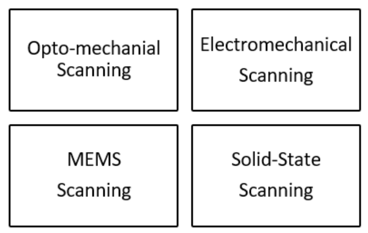
3. Beam Deflection Mechanisms

As stated earlier, a LiDAR instrument without the beam deflection subsystem is often called an LRF. This instrument is only suitable for collecting spatial information from one point to another. In order to obtain the 2D or 3D spatial information from the environment, the laser beam transmitted by the LRF must be deflected. There are several beam deflection mechanisms (often referred to as scanning methods) being employed. They are broadly clustered into four categories: Opto-mechanical, electromechanical, MEMS, and solid-state scanning methods, as shown in Figure 4. In the following subsection, each beam deflection method will be discussed in detail.

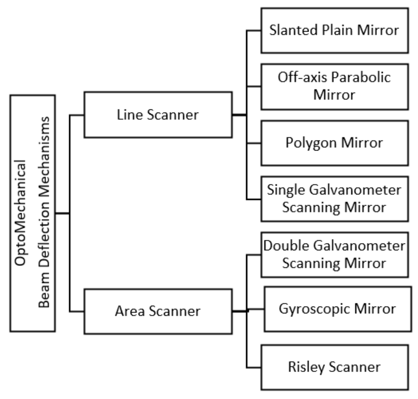
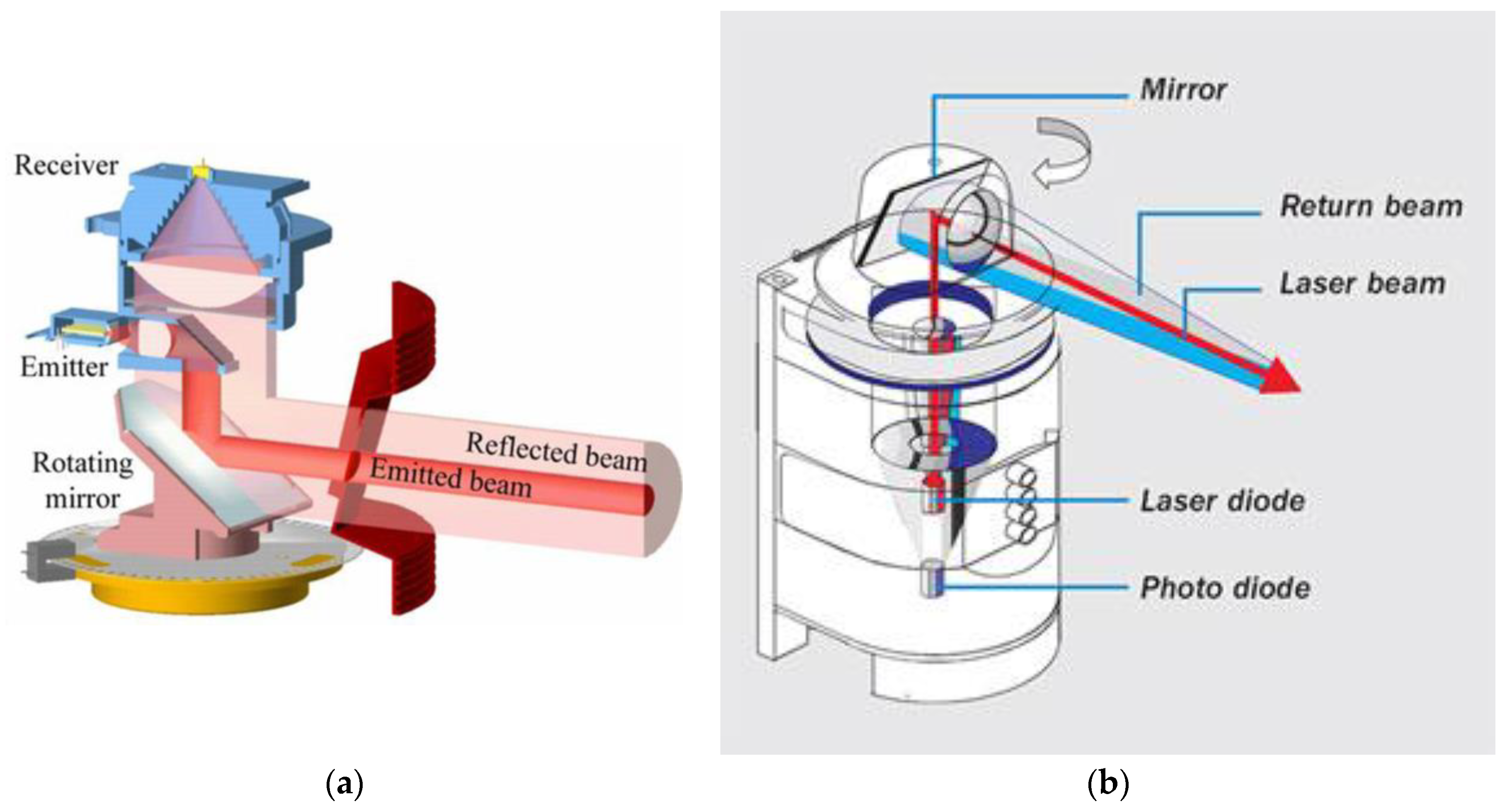
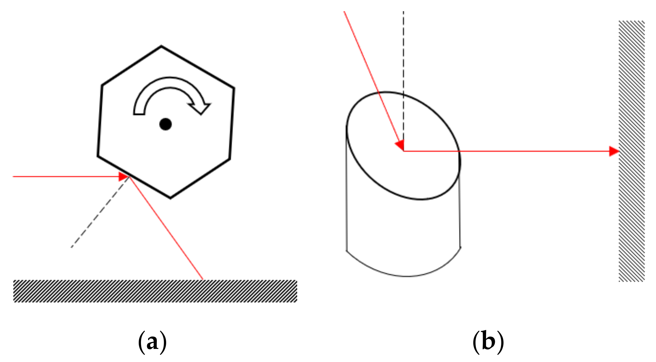
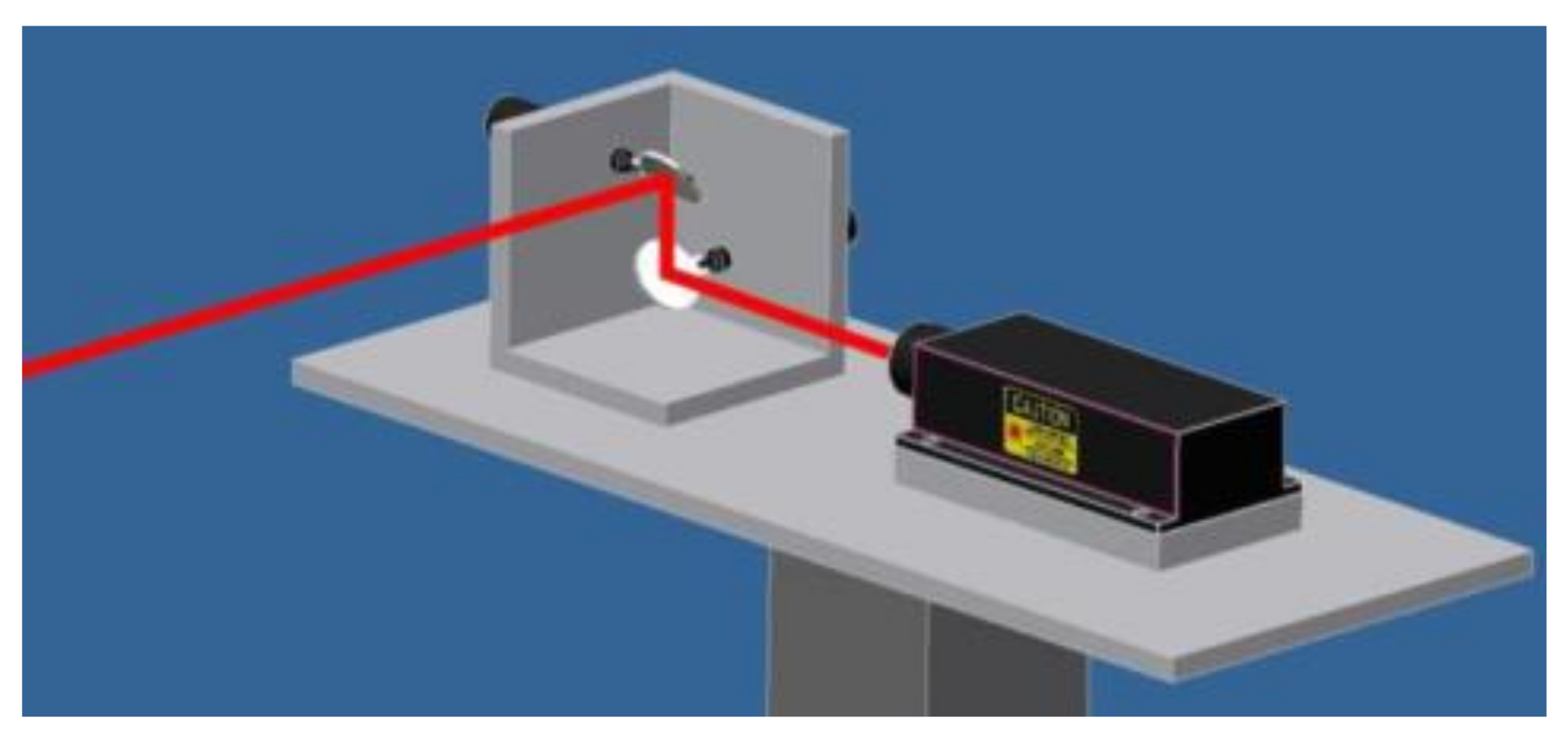
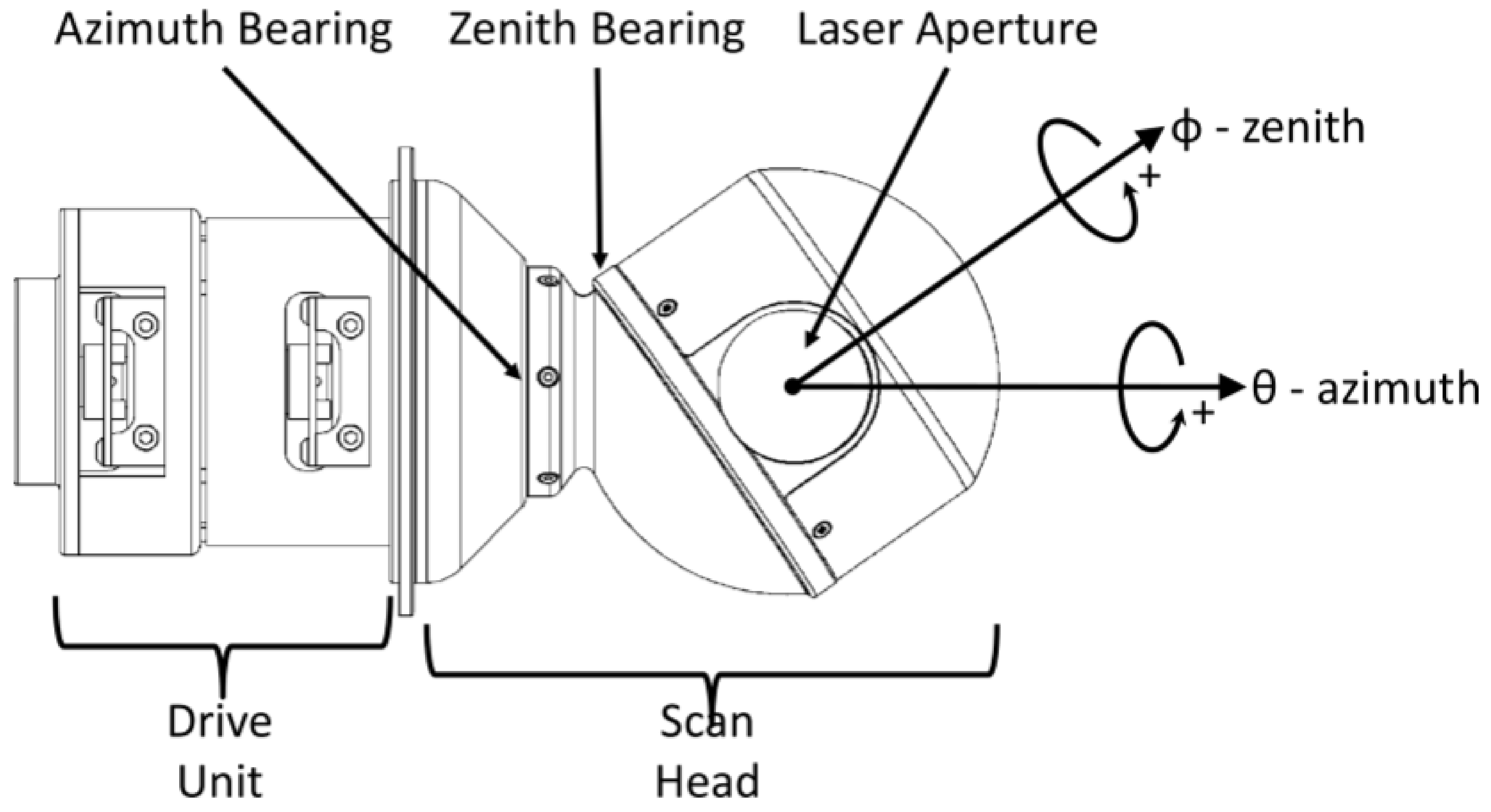
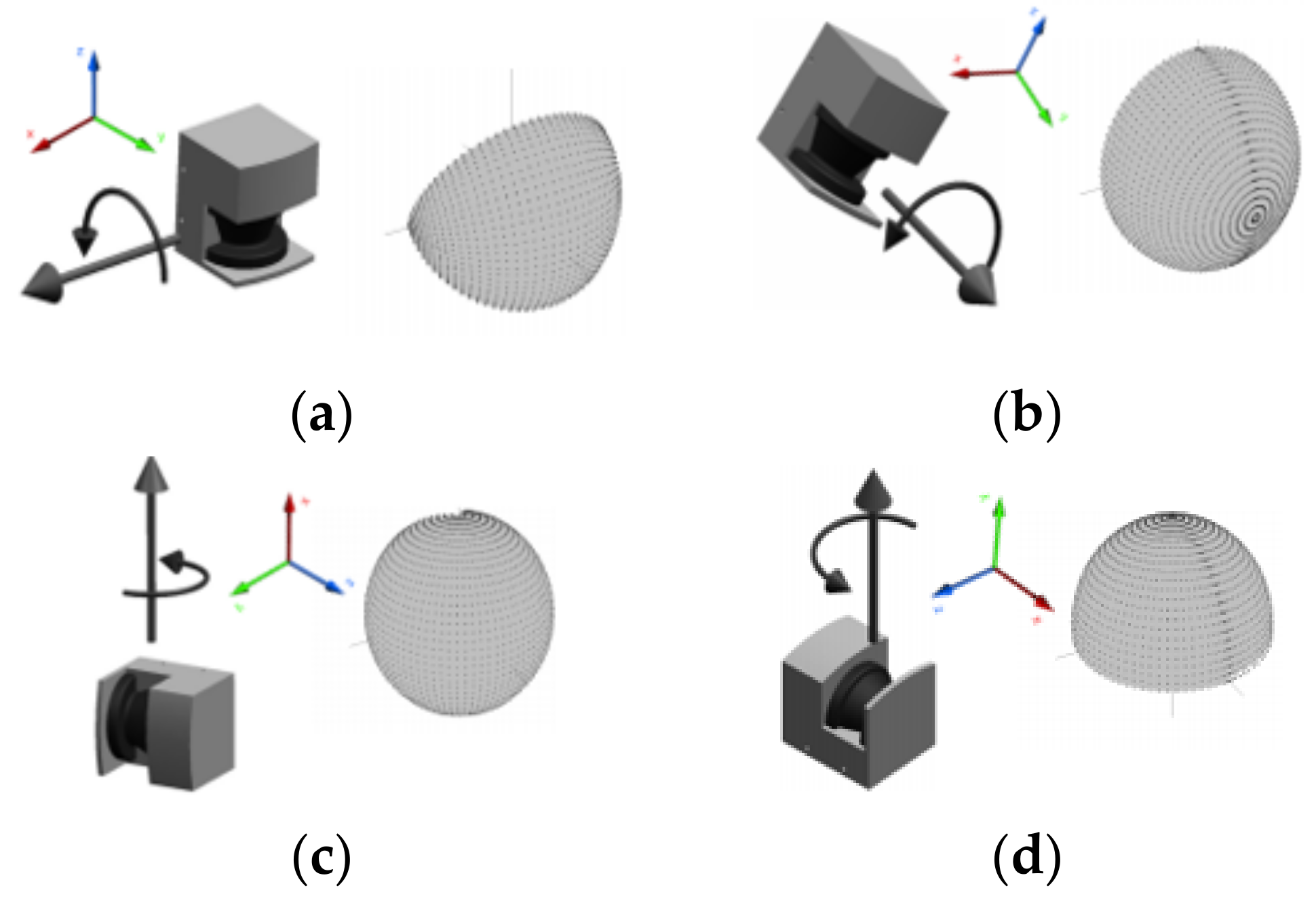
3.1. Optomechanical Scanning

Opto-mechanical scanning refers to the usage of optical components such as mirrors and prisms in aiding the beam deflection. Classifications of commonly employed optomechanical scanning mechanisms in terrestrial LiDAR instruments are presented in Figure 5. The mechanisms are broadly classified into two groups based on the dimension of the measurement. In early days, opto-mechanical scanning is widely preferred because of the fact that LiDAR modules are heavy and bulky. Thus, physically moving the LiDAR increases the system dynamics and creates undesirable effects such as vibrations. Moreover, turning high inertial mass also requires high torque requirements for the motor.
Figure 6a illustrates an opto-mechanical scanning method implemented in a SICK 2D LiDAR instrument. In this instrument, a single mirror mounted at 45 degrees is employed for deflecting the laser beam. This mirror is driven by an electric motor installed at the bottom of the device. This arrangement reduces the design complexity. The laser diode and photodiode utilize the same mirror to transmit and receive laser pulses consecutively, and is thus known as the coaxial type, where both the receiver and transmitter share the same path [15]. FOV of this instrument is limited to 180 degrees. Hence, it is not suitable for applications that require omni-directional scan.
To extend the FOV of the 2D LiDAR instrument, various design strategies were investigated in the past. Figure 6b shows a variation of the SICK LiDAR instrument for the purpose of extending the FOV. In this design, the components are rearranged to achieve an FOV of 360 degrees. Particularly, the mirror is placed on top of the device in contrast to its counterpart shown in Figure 6a. Additionally, the position of the laser diode and photodiode are no longer orthogonal to each other but are located coaxially in a single axis.
Although the FOV of the LiDAR scanner shown in Figure 6b is superior to its counterpart, this design employs a much higher complexity. First, it requires a complex mechanism to drive the mirror. The type of motor employed in these devices is usually tailor-made by manufacturers and thus are not easy to be sourced. Another reason for the complexity is that the scanner utilizes advanced optical apparatus, such as lenses and beam splitters, to focus and guide the laser beam. Therefore, this method is not as feasible to be employed as lab-scale prototypes, despite its omnidirectional scanning capabilities.
Besides the usage of flat mirrors, there are also other types of mirrors, such as polygon and parabolic mirrors, as reported in past literature [17]. An illustration of the scanning mechanism using polygon and parabolic mirrors is presented in Figure 7. One of the disadvantages of using a polygon mirror is that it has limited FOV. Thus, these mechanisms are mostly suitable for applications that require a region scanning, whereby information limited to a rectangular region is required. On the other hand, off-axis parabolic mirrors can scan with a greater FOV in contrast to polygon mirrors. It is most suitable for either bounded or full field scanning in the azimuth plane. Although 2D scanning mechanism using a galvanometer head mirror is possible, there is inadequate information regarding this design in the literature. It is believed that galvanometer scanning mirrors are not popular because of the high initial investment required for its development. Second, the galvanometer scanning mirror have a limited FOV because of the small size of the mirror.
The ability to scan a 3D environment is accomplished by using two mirrors mounted orthogonally to each other. A low-cost 3D LiDAR instrument utilizing galvanometer scan head mirrors was demonstrated by [18] and is illustrated in Figure 8. The major drawback of this method is that the scanner is only capable of scanning a rectangular-shaped FOV. Because of the fact that mirrors are dictated by the law of reflection, the angle of incident ray from normal to the mirror has to be acute. Typically, a 10-mm mirror has an optical angle of ± 20 degrees [18]. In addition, galvanometer scanners are bulky and power consuming. They require a dedicated space to place the bulky driver as well as the stable power supply. Despite their weaknesses, galvanometer scanners offer a simple and flexible solution, especially in the early stage of a prototype design. Once configured, the galvanometer scanner becomes an independent subsystem. Consequently, the laser ranging unit can be easily manipulated without disturbing the scanning subsystem.
Another approach for realizing a 3D scan using gyroscopic mirror is shown in Figure 9 [19]. This design is unique in a way it can function independently from the transceiver unit. The gyroscopic frame of the mirror is controlled by a pair of coaxial gear drive mechanism. Despite the complexity of the driving mechanism, this scanner is capable of operating in three modes: full scan, rectangular scan, and bounded elevation scan. Most recently, a similar concept with different design has been demonstrated by [20]. This design employed two optical components: a mirror and a wedge prism. The rotation of the prism controls the elevation scan while the rotation of the mirror controls the azimuthal scan. As a result, this design offers improved coverage compared to commercial LiDAR Velodyne VLP-16.
Finally, there is a simple yet powerful 2D opto-mechanical beam scanning called Risley scanner, as investigated by [21]. Risley scanner, which is based on Risley optics, is made of a pair of cascaded prisms which can revolve around an optical axis independently. The angle of collimated light entering the prism is refracted by its refractive index. By controlling the angular velocity of the cascaded prisms, a Lissajous scanning pattern is obtained. The major disadvantage for this type of scanner is that the distribution of scanning point is not uniform along the FOV. The density is higher near the center of rotation and drops as it moves away from the origin. A comparison of performance and SWaP specifications for selected optical mechanical LIDAR scanners are presented in Table 1.

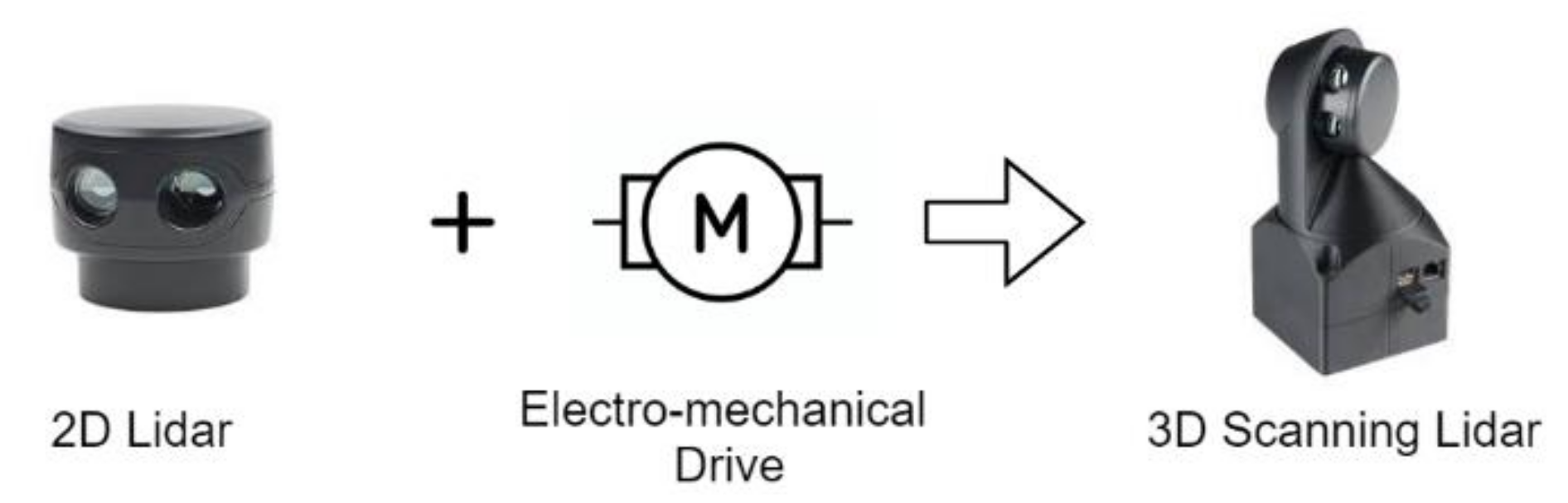
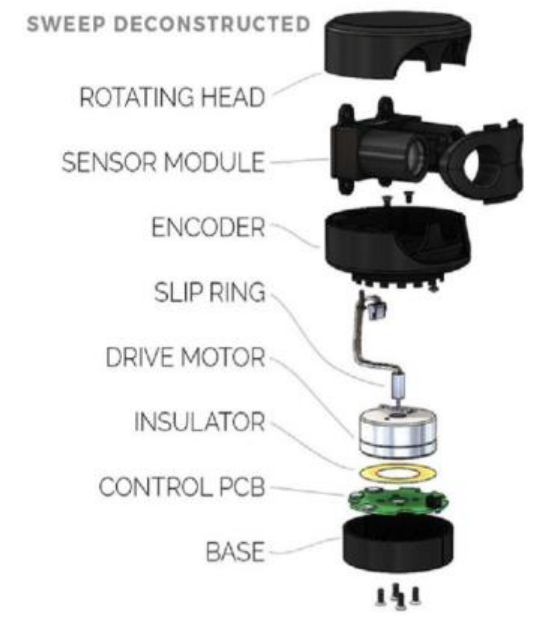
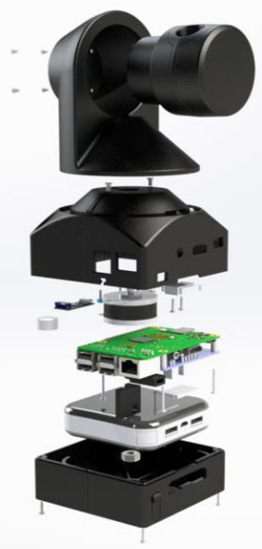
3.2. Electromechanical Scanning

In the beginning of the 21st century, SICK LMS 200/291 [22] and Schemerack LSS 300 [23] were the two competing 2D LiDAR instruments in the market with reasonable price and good performance [24]. A complete teardown of the SICK LMS 291 LiDAR instrument manufactured in the year 2001 was demonstrated by [25]. The SICK LiDAR instrument has influenced researchers to initiate a new era of 3D LiDAR system research. This was the period when electromechanical scanning gained its popularity. Electromechanical scanning refers to the use of electric motors with a mechanical stage to extend the dimensionality of the 2D LiDAR system. To the best of our knowledge, Surmann and coworkers [24] were the first group of researchers to build a low cost 3D LiDAR instrument on the base of a 2D LiDAR system by an extension of a standard servo. In the following years, researchers in [24,26,27,28,29,30,31,32,33,34,35,36,37,38,39,40,41] have adopted this method to design 3D LiDAR systems for various applications.
The 2D LiDAR instrument and electric motors can be orientated and mounted in different possible combinations to obtain a 3D scan. Four of these combinations, namely pitching, rolling, yawing, and top yawing scans are shown in Figure 10. These naming conventions were first coined by Wulf [26] in 2003. The same figure reveals that the FOV and measurement point density is influenced by the orientation of the scanner with respect to the rotation axis. Therefore, it is essential to optimize the orientation of the scanner based on the needs of the application. The first two scanning setups have an FOV of 180 degrees in both scanning axes. Hence, they are suitable for applications requiring region scanning. The remaining two setups are capable of performing a 360-degree scan on the azimuthal axis. However, the setup has an extra advantage where it can perform a bounded scan on the elevation axis.
Thus far, all the scanning schemes discussed above fall under the restricted motion category. In this context, a restricted motion is defined as a periodic oscillation about a fixed starting and ending point as opposed to a continuous motion. The type of motion is dictated by the choice of electric motor, where the motion of a servo motor is limited to 180 degrees while a stepper motor can make a full 360-degree rotation. Nevertheless, it is believed that servo motors were used in the past to avoid design complexity. Without a doubt, the use of servo motors solves the issues of cable connection for the data and power supply to the 2D LiDAR. Because of the restricted motion of the servo motor, there will be no problem of cable entanglement within the arrangement. In addition to that, the closed loop characteristic of a servo motor avoids the need for an external control system.
Although the servo motor offers some advantages, the restricted motion causes undesired effects such as non-uniform acceleration and vibration. At high speed operation, these effects become amplified and cause problems to the performance of the LiDAR instrument. To mitigate the effect of non-uniform acceleration, Wulf et al. [26] has proposed a continuously moving servo drive. By utilizing a continuous drive, a constant velocity is achieved. The cable connections are replaced with slip rings to enable full rotation without wire entanglement. However, the use of slip rings limits the speed of the scanning mechanism and necessitates regular maintenance as they wear out quickly. A comparison of performance and SWaP specifications for selected electromechanical LIDAR scanners are presented in Table 2.

3.3. MEMS Scanning

Micro electromechanical system (MEMS) mirrors offer an alternative solution to optomechanical scanning. These devices are small and light in weight. Numerous works [46,47,48,49,50,51,52,53,54,55,56,57], ([58], p. 1, [59], p. 2), [60,61,62,63,64,65,66] have demonstrated the design of a MEMS LiDAR prototype for robotic and advanced driving assistance systems (ADAS) applications. In 2007, [48] has reported that a MEMS scan module was reduced down to a small volume of 90 mm × 60 mm × 40 mm, weighing less than 40 g and consuming less than 750 mW in power. The low SWaP design of the MEMS mirrors has enabled new applications for autonomous unmanned aerial (UAV) platforms. A more recent publication in 2018 reveals that the size of MEMS scanners has achieved a remarkable form factor of only 4 mm × 4.5 mm × 1.6 mm, and weighs only 16 mg [57].
Albeit the merits of MEMS scanners, there exist several issues that prevent it from being used in UAV and ADAS applications. In previous works, authors have highlighted the fundamental problems of MEMS mirrors. They can attribute to low FOV, low scanning speed, and lack of robustness in control stability. In addition to that, the fabrication and assembly of MEMS mirrors are also ascertained to be cumbersome [53]. FOV of the MEMS scanners remains as one of the unsolved issues. The FOV is often limited to acute angles and may not be suitable for 3D scanning applications. The extension of the scanning angle of MEMS scanners was investigated by [46,48,59,60] using optical methods. To this day, an FOV of 40° × 40° with small spot size for the target at a distance of about 100 m has been reported by [65]. The readers are encouraged to refer to [66] for a more extensive review on MEMS mirrors. A comparison of performance and SWaP specifications for selected MEMS LIDAR scanners are presented in Table 3.

3.4. Solid-State Scanning

The origin of solid-state scanning dates back to the Defense Advanced Research Projects Agency (DARPA) grand challenge between the year 2004 and 2007 where the goal was to navigate a car autonomously in a desert without human intervention. One of the key elements used for object detection and obstacle avoidance is the LiDAR system. However, the LiDAR system requires high scanning rates to be able to perform obstacle detection for navigation purposes. During that time, the average scanning rate reported by [24,26,27] was 9583 points/s, 12,960 points/s, and 24,000 points/s respectively. These values reveal that LiDAR technology at that time was not the best candidate for real-time obstacle detection. Nonetheless, this futuristic competition has prodded researchers and industries to come up with innovative scanning technologies. Based on the lessons learned from the DARPA grand challenge, Velodyne Inc. in 2005 [67] designed a real-time 3D LiDAR system [68] with a scanning rate of 1,300,000 points/s.
The secret behind the extraordinary scanning rate achieved by [68] lies in the technology used for scanning. Unlike the scanning methods presented earlier, the Velodyne LiDAR [68] employed 64 channels (64 laser transceivers) for scanning. This approach is equivalent to theoretically stacking 64 modules of 1D LiDAR instrument all together in one vertical direction. Each channel is separated by an angular displacement of 0.4 degrees, thus giving a total 26.8 degrees FOV in the vertical direction [68]. When these channels are swept 360 degrees in a horizontal direction, a high scanning rate was achieved. It is thus evident that the use of multi-channels for vertical scanning eliminates the need for rotating mechanism. The downside of using multiple channels for scanning is the cost that it entails. Unfortunately, the high cost of the device prevents the public from utilizing the technology. Although Google ADAS research team has demonstrated autonomous cars, the cost of LiDAR systems is still one of the biggest concerns for automobile industries to adapt to this technology.

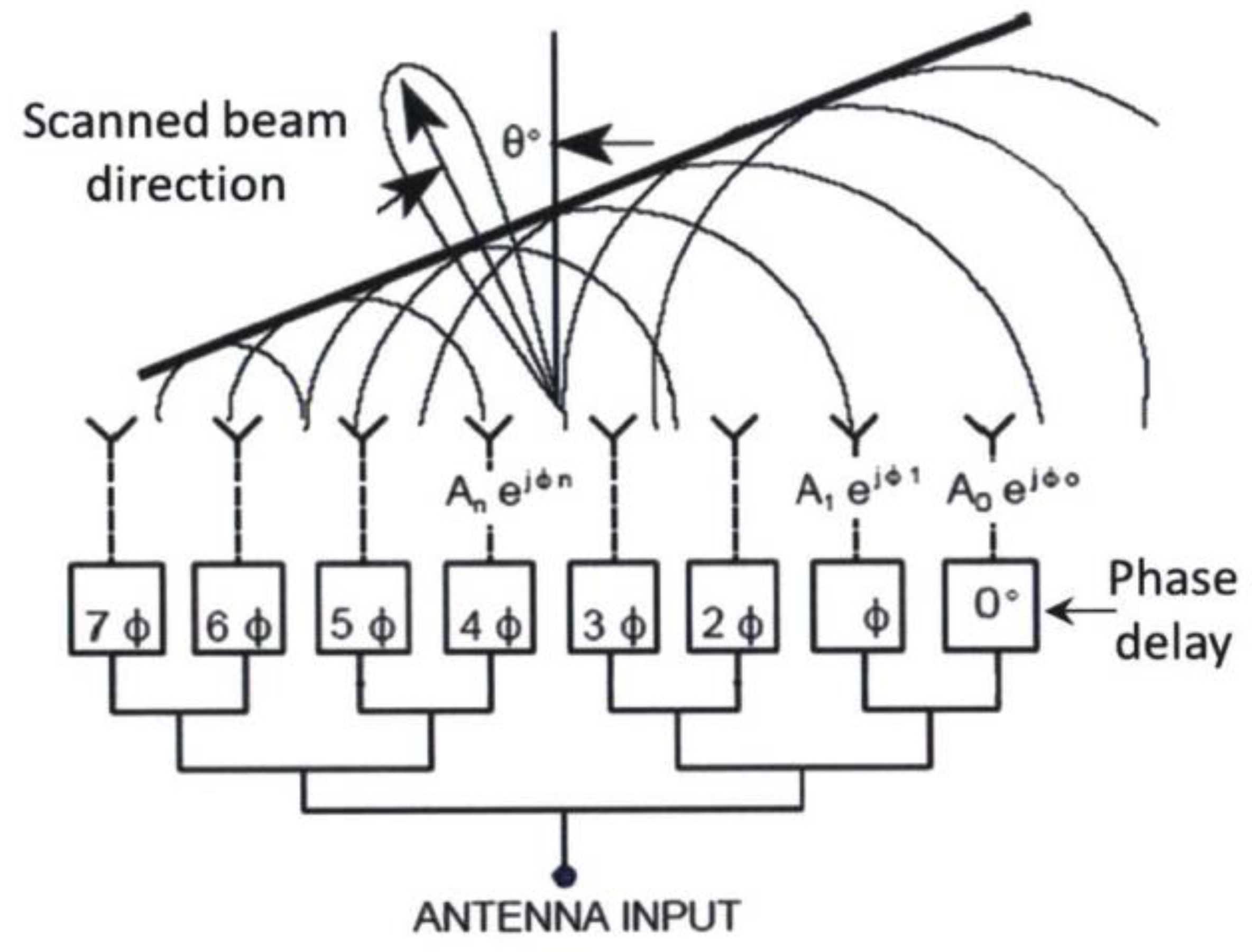
3.4.1. Optical Phased Array (OPA) Beam Scanning

In the efforts of making the LiDAR smaller, cheaper, and faster, a research team from the Photonic Microsystems Group at the Massachusetts Institute of Technology (MIT) has proposed a solid-state LiDAR system on chip solution [69,70,71]. The proposed system utilizes a technique known as optical phased array (OPA) for steering the laser beam. On top of that, the entire system is fabricated on a single chip using silicon photonics platform. OPA is made of an array of light-emitting elements where the phase can be manipulated [72]. Figure 11 illustrates the working principle of an 8-element OPA. The light emitting element consists of three main components: a splitter, a phase controller, and an antenna [73]. The role of the splitter is to distribute coherent light to individual phase shifters. Next, the coherent source reaches the phase shifter block to alter its phase. This block is either realized with an opto-thermal or opto-electrical method. Finally, the modified signal is passed to the optical antenna to be emitted into free space. The antenna is either made of metallic or grating type. Currently, a maximum of 1024 array elements have been demonstrated [74].
The development of LiDAR modules in silicon photonics offers several advantages compared to its counterpart. First, it offers on-chip optics that avoid the need for external optical parts. In conventional LiDAR instruments, optical components such as collimating lens and focusing lens are necessary for directing the beams. Moreover, optical filters are used to suppress noise. Such components increase the overall cost of the LiDAR. Next, it offers on-chip beam steering using OPA and avoid the need for mechanical components. This significantly improves the weight and size of the LiDAR instrument. Furthermore, the avoidance of external optics and mechanical components makes the LiDAR module robust toward mechanical shocks and vibrations. Hence, the LiDAR on chip can sustain harsh environments. Finally, the fabrication process for photonics integrated circuit (PIC) is compatible with existing CMOS process. This significantly reduces the manufacturing overhead.
Apart from research institutions, industries are also actively participating in solid-state LiDAR research and development. Recently, Velodyne Inc. has announced the design for a solid-state LiDAR sensor which is expected to cost under $50 (US dollars), when sold in a high-volume manufacturing scale [69,75,76]. Along with the research institutes and established companies, new companies such as Quanergy Systems (USA) and Innoviz (Israel) are working toward high definition solid-state LiDAR systems [76]. Being a relatively new technology, solid-state scanning is still lacking in the level of technological readiness compared to MEMS scanners [56]. A comparison of performance and SWaP specifications for selected OPA scanners are presented in Table 4.

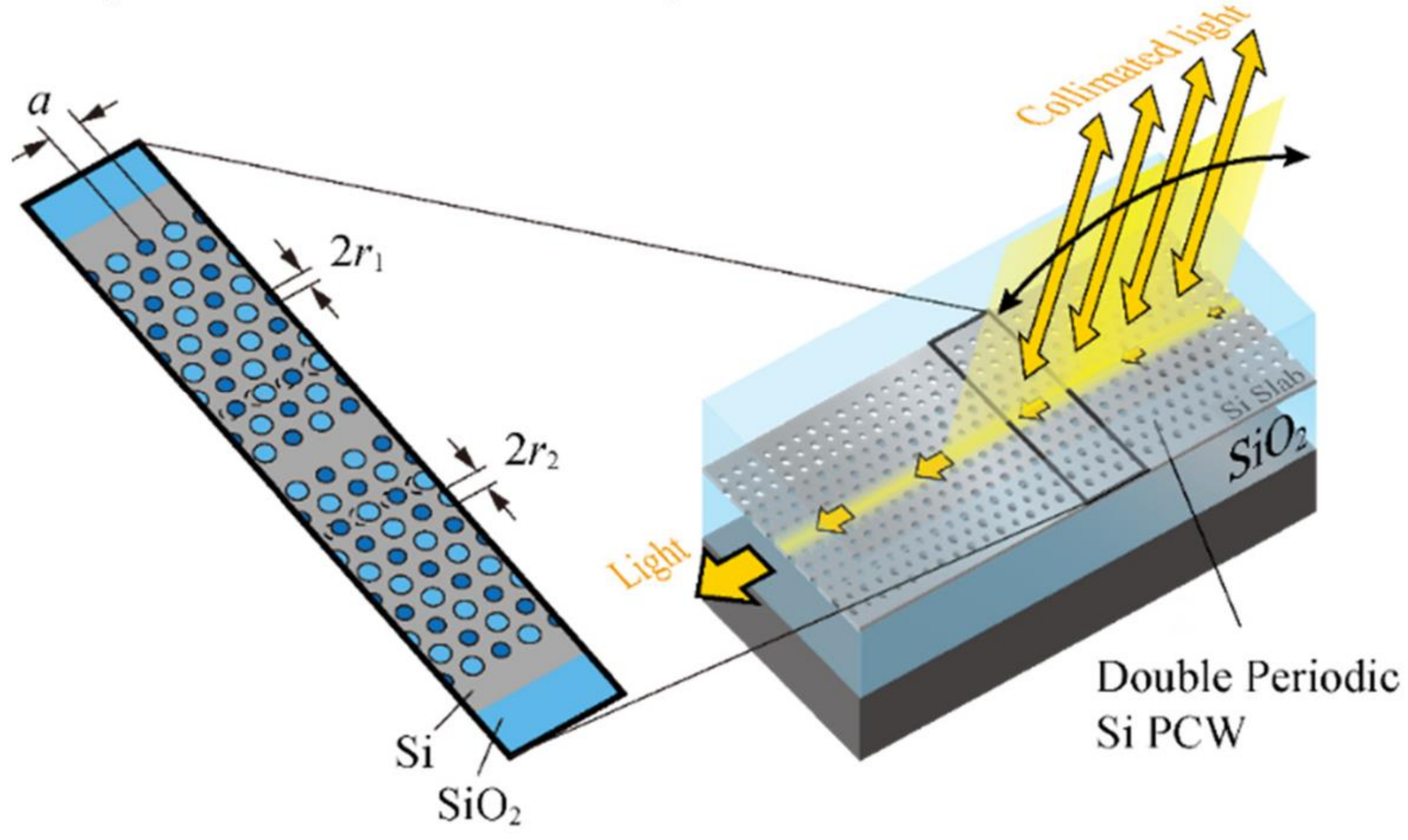
3.4.2. Photonic Crystal Waveguide (PCW) Beam Scanning

In east Asia, specifically in Japan, a team of researchers is taking a different approach to realize solid-state LiDAR systems using slow light technology [77,78,79,80,81]. Slow light technology relies on the manipulation of the group velocity of light. This is completely a different approach in contrast to OPA. Such a manipulation is achieved with the use of silicon photonic crystal waveguide (PCW). Figure 12 illustrates the optical beam steering when a light passes through a PCW. A similar device can be used as a receiver to receive light from free space [77]. To our best knowledge, the term “slow light LiDAR” is coined by this research team group [81]. Although a total integration of transmission and reception has not been established yet, the team advocates that slow light LiDAR can overcome the pitfalls of OPA technology.
In a nutshell, solid-state scanning method involves the steering of laser pulses by using nonmoving components in contrast to rotating system which utilizes mirrors and lenses. The advantages of solid-state scanning include the elimination of noise, small form factor, improved FOV, improved scanning rate and increased robustness. At the moment, the two competing technologies for solid-state scanning are OPA and photonic crystal. Although solid-state scanning has many advantages compared to its counterparts, there are several challenges that needs to be addressed. Fundamental issues such as dispersion of light at long distances as well as fabrication issues like limitation of materials and processes are some of the challenges awaiting to be tackled [56]. A comparison of performance and SWaP specifications for selected PCW scanners is presented in Table 5.

4. Discussion

Electromechanical scanning methods were predominantly used for extending dimensionality of 2D LiDAR instruments as demonstrated by past researchers [25,27,28,29,30,31,32,33,34,35,36,37,38,39,40,41,42]. However, only a handful of researchers have considered extending the dimensionality of a 1D LiDAR using electromechanical scanning methods in the past. As stated earlier, the weight of the LiDAR is the main limiting factor that dictates the selection of appropriate scanning methods. In recent years, advancement in photonics industry has led to the emergence of new LiDAR products in the market such as SF Lidar (Ligthwave optoelectronics) [82,83,84], LidarLite (Garmin) [85,86], Rplidar (Slamtec) [87], Sweep (Scanse) [44], Tera One (Terabee) [43], and TFmini (Beneware) [88]. Currently, the LiDAR instruments have achieved low size, weight, and power (SWaP) design compared to [22]. Since weight is no longer an issue now, researchers began to reconsider using electromechanical scanning methods for designing a 3D LiDAR using a 1D LiDAR module. For instance, [40] has demonstrated the conceptual design of a 2D LiDAR using a 1D LiDAR module and a servo motor. On top of that, custom made gear trains are utilized to extend the rotation of the servo motor to up to 360 degrees. As a step further, the design of a 3D scanner using a 1D LiDAR and stepper motor has been demonstrated by [41]. Finally, there exist a number of commercially available 2D and 3D LiDAR sensors which employ electromechanical scanning method in their design. For instance, 2D LiDAR systems such as Sweep [44], Terabee [43], and Rplidar [87] has adopted similar conceptual design demonstrated by [41]. However, they were implemented using DC motor with encoder to achieve full azimuthal scan.
The facts presented thus far has indicated that the pulsed TOF LiDAR design has gone through a progressive growth. Lower SWaP designs are seen in later LiDAR instruments, owing to the advancement of high-density circuit integration. The efforts for integrating electronic and optoelectronic circuits for LiDAR application dates back to the works of Pasi [89]. In this work, Pasi has demonstrated an ASIC solution for a LiDAR receiver which consists of photodiodes, amplifiers, and time-to-digital converters (TDCs) implemented using the BiCMOS process as depicted in Figure 13. The design was reported to hit the measurement accuracy of millimeters over a range of 4 to 34 m. In subsequent years, more research works in the integrated receiver design striving toward high speed and accuracy has been reported in [90]. On the other hand, the development in the LiDAR industry is in step with research works and has gained exclusiveness in the LiDAR design. To date, VL6180 [91], VL530L [92], and ISL2950 [93] are LiDAR sensors that have been successfully fabricated as standalone system on chip (SoC) designs. These integrated circuits (ICs) are capable of driving external laser diodes, receiving pulse from photodiode and computing TOF. They are even capable of communicating with a host microcontroller by means of inter-integrated circuit (I2C) protocol. The architectures of VL6180 [91] and ISL29501 [93] is shown in Figure 14 and Figure 15 respectively. The main difference between VL6180 and ISL29501 lies in the implementation of signal processing pipeline. VL6180 employs a microcontroller whereas the ISL29501 uses an on-chip DSP circuit to process the signals. Besides that, the ISL29501 provides the option of using external laser diodes and photodiodes if the application requires them. It is evident that the SoC design has influenced the traditional architecture used in previous LiDAR designs.
In the emergence of new LiDAR designs, the decision on whether to buy it or built it needs to be justified. The main objective of academic research in LiDAR designs is cost reduction. However, it is evident that LiDAR manufacturers are aware of the costing issues and have taken several measures to keep the overall price low. First, most manufacturers have made the decision to employ laser diodes in the near infrared (NIR) band. This is on the grounds that optoelectronic devices in NIR band has become inexpensive and easily available because of the advent of fiber optics communication industry. On top of that, NIR lasers are invisible and cause less harm to the eyes. Second, p-i-n photodiode is preferred over avalanche photodiode (APD) for its lower cost despite its drawbacks. Although APD theoretically has a higher gain than p-i-n diodes, the additional circuits for supplying high voltage add an overhead to the overall cost of the LiDAR instrument. For medium range operation, p-i-n photodiodes exhibit a satisfactory level of performance, making the use of APDs unnecessary. Finally, LiDAR manufacturers employ SoC signal processing technology to integrate all the required functions necessary for LiDAR operation. Figure 16 shows the architecture of the LiDAR Lite V2 (Pulse light) [86]. It can be observed that the SoC processing core employed in Lidarlite V2 [86] is made of an 8 bit microcontroller to handle the control and communications; a sampling circuits to capture and down sample the logic state of external comparator; and a transmit signal generator to generate waveform patterns and a correlation processor to perform correlation operations of the incoming signal. This small form factor solution reduces the complexity and power consumption issues of the overall system. As a comparison, Kelden [94] in his design spent a total of 125 Euros excluding manufacturing and miscellaneous costs. Despite this, the author claimed that they failed to produce a working prototype because of the use of cheap development procedure and lack of expertise. Meanwhile, commercially available LiDAR instruments such as the LiDAR Lite V3 [85] costs the same amount as quoted by Kelden [94] but with better performance. In conclusion, purchasing an off-the-shelf 1D LiDAR modules is a better alternative to building a module from scratch for applications that require medium operating range and centimeter level resolution.
The status of 2D and 3D LiDAR developments are slightly different compared to the 1D LiDAR counterpart. The development of 3D LiDAR instruments is an ongoing research. As the costs of commercially available 3D LiDAR instruments are still high, some studies from the literature have proposed alternative methods in developing a 3D LiDAR system. The first option is to mount a 2D LiDAR instrument onto a mechanical platform. Various platforms utilizing rotating (tilting), revolving, and oscillating motions were proposed. Among all the proposed methods, mounting a 2D LiDAR instrument onto a tilting unit has gained the most popularity in 3D LiDAR system development. Presently, the latest development in the field involves converting a 1D LiDAR instrument into a 3D LiDAR system. The conversion is done in two stages. In the first stage, the 1D LiDAR instrument is converted to a 2D LiDAR system by an actuator as illustrated in Figure 17. Commercially available LiDAR instruments such as Sweep [44] is constructed based on this conceptual design, utilizing a 1D LiDAR module developed by Garmin [85]. Figure A1 shows the exploded view of the Sweep LiDAR for greater insights on the hardware implementation. The main drawback of this method is that the scanning performance is influenced by the module itself. The current LiDAR module requires 40 milliseconds to perform an individual acquisition, limiting the update rate. Nevertheless, at a cost of $250 with the capability of 40-m detection range and centimeter resolution, the Sweep LiDAR is a very attractive proposition for obstacle detection application in robotics. The following year after the publication date of [44], the developers of Sweep has initiated an open source project called sweep DIY scanner kit. The objective of this project is to convert the existing Sweep 2D LiDAR into a 3D LiDAR system as illustrated in Figure 18, thus completing the conversion from 1D to 3D. The conversion is done by mounting the Sweep onto a stepper motor. Figure A2 shows the exploded view of a DIY 3D scanner kit. Despite its inherent weakness of lower scanning rate, the prototype can produce a 3D map of the environment within a few minutes [45]. The application for this type of LiDAR system includes collision detection for unmanned vehicles platform, surveying application such as confined space measurement as well as for research and education.
Although the LiDAR systems mentioned above have reach a satisfactory level of improvements, it still lacks in specifications to be employed in ADAS application. The requirements of LiDAR systems for ADAS application have been discussed earlier by [70,81] and are presented in Table 6. There are three specifications: range, resolution, and safety, which depends upon the LiDAR transceiver unit. Most of the commercial LiDAR operating below 100 m are based on TOF principle. However, for applications require sensing beyond few hundred meters continuous wave (CW) LiDAR are commonly used. The main reason TOF is preferred over CW LiDAR is due to eye safety. A short high-power impulse is safe and does not damage the human eye. However, such a technique is no longer suitable for detecting distance above 100 m unless it includes highly sensitive detectors such as photomultiplier tube (PMT). As an alternative, CW LiDAR operating on 1550 nm is being considered. Besides that, with CW LiDAR design, an improved resolution and power dissipation can be achieved. The rest of the specifications listed in Table 6 is highly influenced by the scanning mechanism. It is evident that the LiDAR instruments available in the market are unable to achieve a high-speed scanning exceeding 25 frame per second (fps) under the budget of $200. Hence, mechanical scanning is clearly not the best candidate for this application. The MEMS scanning appears to be a suitable candidate for ADAS because it is small, lightweight, low power, and cheap. However, the main drawback in the size of the mirror violates the horizontal FOV requirements. Increasing the mirror size will not solve the problem because it will reduce its abilities to work in high speed [81]. Clearly, for this application an innovative solution such as OPA LiDAR or slow light LiDAR are required.

5. Conclusions

In conclusion, a comprehensive review on state-of-the-art LiDAR scanning mechanisms has been reported. The sources of the literature are based on past research works and commercial products. Mechanical scanning mechanism is the most matured technology as less research is being reported lately. It is evident that (After many iterations and improvements), current commercially available 1D TOF LiDAR instrument has achieved remarkable progress in terms of design (i.e., size, weight, and power) and performance (i.e., range, resolution, and accuracy). This has turned the user’s attention to construct self-made 3D LiDAR systems. Among all the existing options, the conversion from a 1D LiDAR to a 3D LiDAR system is currently the best option in terms of cost. However, this method suffers from low scanning rates, which makes it unsuitable for applications requiring high speed operations. Despite its weaknesses, the low cost of this 3D LiDAR system makes it an attractive solution for applications such as robotics, surveying, agriculture, and education.
Besides mechanical scanning, MEMS scanning has gained huge attention as a novel solution for applications with low SWaP requirements. It is by far the more matured technology compared to solid-state scanning. Currently a great emphasis is given in increasing the robustness of the MEMS scanners so that it can meet the requirements for use in ADAS applications, with existing solutions already sufficient for use in UAV implementations.
Finally, there is a huge expectation for solid-state LiDAR systems to fill in the gap in ADAS application. The two-competing technology under these categories are OPA and PCW. Currently, the readiness level of this technology is still low compared to MEMS scanners. Since solid-state scanning is believed to have superior robustness, FOV, and scanning rate potential, both academics and industries are putting in a lot of effort to further develop this technology.

Author Contributions

Investigation and manuscript preparation, T.R. and F.H.H.; methodology and writing—review, A.B.H. and M.F.I.; supervision, A.H. All authors have read and agreed to the published version of the manuscript.

Funding

This study was partially supported by the Universiti Kebangsaan Malaysia research grant, DIP-2018-020.

Conflicts of Interest

The authors declare no conflict of interest.

Appendix A

Figure A1. Exploded view of Scanse Sweep 2D LiDAR design [45].
Electronics 09 00741 g0a1
Figure A2. Exploded view of Scanse Sweep 3D LiDAR design [45].
Electronics 09 00741 g0a2

References

  1. Liner, J. SWaP: The RF Solution that Can Mean the Difference between Flying High and Being Grounded; Analog Devices: Norwood, MA, USA, 2015. [Google Scholar]
  2. Robin, G.J.; Jacky, C. Making a difference: Examples of the use of repeat LiDAR datasets to guide river management decisions following extreme floods. In Proceedings of the 7th Australian Stream Management Conference, Townsville, Australia, 27–30 July 2014; pp. 232–239. [Google Scholar]
  3. Eitel, J.U.H.; Hö, B.; Vierling, L.A.; Abellán, A.; Asner, G.P.; Deems, J.S.; Glennie, C.L.; Joerg, P.C.; Lewinter, A.L.; Magney, T.S.; et al. Beyond 3-D: The new spectrum of lidar applications for earth and ecological sciences. Remote Sens. Environ. 2016, 186, 372–392. [Google Scholar] [CrossRef] [Green Version]
  4. Bosch, T. Laser ranging: A critical review of usual techniques for distance measurement. Opt. Eng. 2001, 40, 10. [Google Scholar] [CrossRef]
  5. Ebrahim, M.A.-B. 3D Laser Scanners’ Techniques Overview. Int. J. Sci. Res. 2015, 4, 5–611. [Google Scholar]
  6. Berkovic, G.; Shafir, E. Optical methods for distance and displacement measurements. Adv. Opt. Photonics 2012, 4, 441. [Google Scholar] [CrossRef]
  7. Nuchter, A. 3D Robotic Mapping. In Springer Tracts in Advanced Robotics; Springer: Berlin/Heidelberg, Germany, 2009; Volume 52. [Google Scholar]
  8. NASA. 2016 Lidar Technologies Review and Strategy; NASA Earth Science Technology Office: Greenbelt, MD, USA, 2016; p. 80. [Google Scholar]
  9. Toth, C.; Józ, G. Remote sensing platforms and sensors: A survey. J. Photogramm. Remote Sens. 2015, 115, 22–36. [Google Scholar] [CrossRef]
  10. Oludare, I.M.; Pradhan, B. A decade of modern cave surveying with terrestrial laser scanning: A review of sensors, method and application development. Int. J. Speleol. 2016, 45, 71–88. [Google Scholar] [CrossRef] [Green Version]
  11. Molebny, V.; Mcmanamon, P.; Chen, W. Laser radar: Historical prospective—From the East to the West. Opt. Eng. 2017, 56, 031220. [Google Scholar] [CrossRef]
  12. Colomina, I.; Molina, P. Unmanned aerial systems for photogrammetry and remote sensing: A review. ISPRS J. Photogramm. Remote. Sens. 2014, 92, 79–97. [Google Scholar] [CrossRef] [Green Version]
  13. Xinzhao, C. Lecture 07, Fundamentals of Lidar remote sensing. 2012. Available online: http://superlidar.colorado.edu/Classes/Lidar2012/LidarLecture07_Architecture.pdf (accessed on 4 December 2019).
  14. Xinzhao, C. Lecture 08, Fundamentals of Lidar remote sensing. 2016. Available online: http://superlidar.colorado.edu/Classes/Lidar2016/Lidar2016_Lecture08_Architecture.pdf (accessed on 4 December 2019).
  15. Xinzhao, C. Lecture 36, Lidar Architecture and Lidar Design. 2016. Available online: http://superlidar.colorado.edu/Classes/Lidar2016/Lidar2016_Lecture36_LidarDesignArchitecture.pdf (accessed on 4 December 2019).
  16. Xinzhao, C. Lecture 41, Lidar Architecture and Lidar Design. 2012. Available online: http://superlidar.colorado.edu/Classes/Lidar2012/LidarLecture41_LidarDesign1.pdf (accessed on 4 December 2019).
  17. Li, Z.; Chen, J.; Baltsavias, E. Advances in Photogrammetry, Remote Sensing and Spatial Information Sciences: 2008 ISPRS Congress Book, 1st ed.; CRC Press: Boca Raton, FL, USA, 2008; ISBN 978-0-415-47805-2. [Google Scholar]
  18. Hegna, T.A.; Pettersson, H.; Teknova, K.G.; Laundal, K.M. Inexpensive 3-D Laser Scanner System Based on A Galvanometer Scan Head. In Proceedings of the Optical Measurement Systems for Industrial Inspection VII, Munich, Germany, 23–26 May 2011. [Google Scholar]
  19. Wood, D.; Bishop, M. A Novel Approach to 3D Laser Scanning. In Proceedings of the Australasian Conference on Robotics and Automation, Victoria University of Wellington, Wellington, New Zealand, 3–5 December 2012. [Google Scholar]
  20. Niewola, A.; Podsedkowski, L. A novel 3D laser scanner design for variable density scanning. In Proceedings of the 12th International Workshop on Robot Motion and Control (RoMoCo), Poznań, Poland, 8–10 July 2019; pp. 197–202. [Google Scholar] [CrossRef]
  21. Vuthea, V.; Toshiyoshi, H. A Design of Risley Scanner for LiDAR Applications. In Proceedings of the 2018 International Conference on Optical MEMS and Nanophotonics (OMN), Lausanne, Switzerland, 29 July–2 August 2018; pp. 1–2. [Google Scholar]
  22. Sick LMS200/211/221/291 Laser Measurement Systems Technical Description; SICK AG: Waldkirch, Germany, 2006.
  23. Schmersal Schmersal Newsletter 02 Automotive; Schmersal: Wuppertal, Germany, 2003.
  24. Surmann, H.; Nuchter, A.; Hertzberg, J. An autonomous mobile robot with a 3D laser range finder for 3D exploration and digitalization of indoor environments. Robot. Auton. Syst. 2003, 45, 181–198. [Google Scholar] [CrossRef]
  25. Kohanbash, D. SICK LMS Full LIDAR Teardown. Available online: http://robotsforroboticists.com/sick-lms-lidar-teardown/ (accessed on 4 December 2019).
  26. Wulf, O.; Wagner, B. Fast 3D Scanning Methods for Laser Measurement Systems, 2003; pp. 312–317. Available online: https://pdfs.semanticscholar.org/633d/42113180b581e64ac04b846cb55c6b9bffd2.pdf (accessed on 4 December 2019).
  27. Surmann, H.; Worst, R. New Applications with Lightweight 3D Sensors. In Proceedings of the Joint Conference on Robotics. ISR 2006, 37th International Symposium on Robotics, and ROBOTIK 2006, 4th German Conference on Robotics, München, Germany, 15–17 May 2006. [Google Scholar]
  28. Surmann, H.; Lingemann, K.; Nuchter, A.; Hertzberg, J. Fast acquiring and analysis of three dimensional laser range data. In Proceedings of the 6th International Fall Workshop Vision, Modeling and Visualization, Stuttgart, Germany, 21–23 November 2001; pp. 59–66. [Google Scholar]
  29. Xiang, Z.; Wu, E. Design and calibration of a fast 3D scanning LADAR. In Proceedings of the Design and Calibration of a Fast 3D Scanning LADAR, Luoyang, Henan, China, 25–28 June 2006; pp. 211–215. [Google Scholar]
  30. Harrison, A.; Newman, P. High quality 3D laser ranging under general vehicle motion. In Proceedings of the 2008 IEEE International Conference on Robotics and Automation, Pasadena, CA, USA, 19–23 May 2008; pp. 7–12. [Google Scholar]
  31. Chong, Z.J.; Qin, B.; Bandyopadhyay, T.; Ang, M.; Frazzoli, E.; Rus, D. Synthetic 2D LIDAR for precise vehicle localization in 3D urban environment. In Proceedings of the IEEE International Conference on Robotics and Automation (ICRA), Karlsruhe, Germany, 6–10 May 2013; pp. 1554–1559. [Google Scholar]
  32. Gao, M.; Chen, W.; Li, B.; Lv, T. Construction and realization of a 3D perceptual system based on 2D laser radar. In Proceedings of the 2008 3rd IEEE Conference on Industrial Electronics and Applications, Singapore, 3–5 June 2008; pp. 680–684. [Google Scholar]
  33. Maurelli, F.; Droeschel, D.; Wisspeintner, T.; May, S.; Surmann, H. A 3D laser scanner system for autonomous vehicle navigation. In Proceedings of the 2009 International Conference on Advanced Robotics, Munich, Germany, 22–26 June 2009. [Google Scholar]
  34. Segovia, A.; Contreras, A.; Garduno, M.P. Mechanical Analysis of a Vertical Scanning System for 3D Images Acquisition with Microcontroller-Based Electronic Design; World Scientific and Engineering Academy and Society (WSEAS): Stevens Point, WI, USA, 2010; Volume 9, pp. 180–191. [Google Scholar]
  35. Segovia, A.; Contreras, A.; Garduno, M.P. Design and Development of a Vertical Scanning System for 3D Images Acquisition. In Proceedings of the 2nd WSEAS International Conference on Sensors, and Signals and Visualization, Imaging and Simulation and Materials Science (SENSIG’09/VIS’09/MATERIALS’09), Stevens Point, WI, USA, November 2009; pp. 88–93. [Google Scholar]
  36. Reina, G.; Giannoccaro, N.I.; Messina, A.; Gentile, A. Mobile robot perception using an inexpensive 3-D laser rangefinder. In Proceedings of the 2010 IEEE International Symposium on Industrial Electronics, Bari, Italy, 4–7 July 2010; pp. 2809–2814. [Google Scholar] [CrossRef]
  37. Gutierrez, M.A.; Martinena, E.; Sanchez, A.; Rodriguez, R.G.; Nunez, P. A Cost-Efficient 3D Sensing System for Autonomous Mobile Robots. In Proceedings of the XII Workshop of Physical Agents (WAF 2011), Albacete, Spain, 5–6 September 2011. [Google Scholar]
  38. Yong-kun, W.; Ju, H.; Xing-shun, W. A real-time robotic indoor 3D mapping system using duel 2D laser range finders. In Proceedings of the 33rd Chinese Control Conference, Nanjing, China, 28–30 July 2014. [Google Scholar]
  39. Chou, Y.-S.; Liu, J.-S. A Robotic Indoor 3D Mapping System Using a 2D Laser Range Finder Mounted on a Rotating Four-Bar Linkage of a Mobile Platform. Int. J. Adv. Robot. Syst. 2013, 10. [Google Scholar] [CrossRef]
  40. Duong, E. LiDAR Based Home Mapping: Using the OSLRF-01 and Arduino to Generate Floor Plans. Available online: https://soe.rutgers.edu/sites/default/files/imce/pdfs/gset-2014/GSET2015-LIDAR.pdf (accessed on 4 December 2019).
  41. Reyes, A.L.; Cervantes, J.M.; Gutiérrez, N.C. Low Cost 3D Scanner by Means of a 1D Optical Distance Sensor. Procedia Technol. 2013, 7, 223–230. [Google Scholar] [CrossRef] [Green Version]
  42. RoboPeak Team RPLIDAR Low Cost 360 degree 2D Laser Scanner (LIDAR) System Introduction and Datasheet. 2014. Available online: https://www.robotshop.com/media/files/pdf/rplidar-a1m8-360-degree-laser-scanner-development-kit-datasheet-1.pdf (accessed on 23 April 2020).
  43. Terabee. Teraranger One; Terabee: Saint-Genis-Pouilly, France, 2016; Volume 53, pp. 1689–1699. [Google Scholar]
  44. Scanse, Sweep v1.0 User Manual and Technical Specification; Scanse. 2017. Available online: https://s3.amazonaws.com/scanse/Sweep_user_manual.pdf (accessed on 23 April 2020).
  45. Leeman, J. Scanse Sweep 3D Scanner Review, Servo Magazine. September 2017. Available online: https://www.servomagazine.com/magazine/article/the-multi-rotor-hobbyist-scanse-sweep-3d-scanner-review? (accessed on 4 December 2019).
  46. Stann, B.L.; Dammann, J.F.; Giza, M.M.; Jian, P.-S.; Lawler, W.B.; Nguyen, H.M.; Sadler, L.C. MEMS-scanned ladar sensor for small ground robots. In Proceedings of the SPIE Defense, Security and Sensing, Orlando, FL, USA, 5–9 April 2010; Volume 7684. [Google Scholar]
  47. Moss, R.; Yuan, P.; Bai, X.; Quesada, E.; Sudharsanan, R.; Stann, B.L.; Dammann, J.F.; Giza, M.M.; Lawler, W.B. Low-cost compact MEMS scanning ladar system for robotic applications. In Proceedings of the SPIE Defense, Security and Sensing, Baltimore, MD, USA, 24–26 April 2012; Volume 8379. [Google Scholar]
  48. Kasturi, A.; Milanovic, V.; Atwood, B.H.; Yang, J. UAV-borne lidar with MEMS mirror-based scanning capability. In Proceedings of the SPIE Defense, Security and Sensing, Baltimore, MD, USA, 20 April 2016; Volume 9832. [Google Scholar]
  49. Adamo, G.; Mistretta, L.; Livreri, P.; Busacca, A. A LiDAR Prototype with Silicon Photomultiplier and MEMS Mirrors. In Proceedings of the IEEE 4th International Forum on Research and Technologies for Society and Industry, Palermo, Italy, 10–13 September 2018; pp. 1–5. [Google Scholar]
  50. Strasser, A.; Stelzer, P.; Steger, C.; Druml, N. Speed-Up of MEMS Mirror’s Transient Start-Up Procedure. In Proceedings of the SAS 2019—2019 IEEE Sensors Applications Symposium, Sophia Antipolis, France, 11–13 March 2019; pp. 1–5. [Google Scholar]
  51. Lu, H.-Y.; Lu, C.-E.; Huang, Z.-R.; Lin, S.; Lo, S.-C.; Chen, R.; Fang, W. Fabrication and Integration of Binary Phased Fresnel Lens and Micro Linear Actuator for IR Laser Beam Scanning Application. In Proceedings of the 2019 20th International Conference on Solid-State Sensors, Actuators and Microsystems & Eurosensors XXXIII, Berlin, Germany, 23–27 June 2019; pp. 1584–1587. [Google Scholar]
  52. Wang, D.; Watkins, C.; Koppal, S.; Li, M.; Ding, Y.; Xie, H. A Compact Omnidirectional Laser Scanner Based on an Electrothermal Tripod Mems Mirror for Lidar Please Leave. In Proceedings of the 2019 20th International Conference on Solid-State Sensors, Actuators and Microsystems & Eurosensors XXXIII, Berlin, Germany, 23–27 June 2019; pp. 1526–1529. [Google Scholar]
  53. Niclass, C.; Ito, K.; Sago, M.; Matsubara, H.; Kato, S.; Kagami, M. Design and characterization of a 256 × 64-pixel single-photon imager in CMOS for a MEMS-based laser scanning time-of-flight sensor. Opt. Express 2012, 20, 11863–11881. [Google Scholar] [CrossRef] [PubMed]
  54. Xu, F.; Qiao, D.; Song, X.; Zheng, W.; He, Y.; Fan, Q. A Semi-coaxial MEMS-based LiDAR. In Proceedings of the IECON 2019—45th Annual Conference of the IEEE Industrial Electronics Society, Lisbon, Portugal, 14–17 October 2019; Volume 1, pp. 6726–6731. [Google Scholar]
  55. Takeaki, K.; Takashi, S.; Kazuhiro, H. Cycloidal scanning with MEMS micro mirror for an omnidirectional long range LiDAR. In Proceedings of the International Conference on Optical MEMS and Nanophotonics, Daejeon, Korea, 28 July–1 August 2019; pp. 142–143. [Google Scholar]
  56. Pensala, T.; Kiihamaki, J.; Kyynarainen, J.; Dekker, J.; Gorelick, S.; Pekko, P.; Pernu, T.; Ylivaara, O.; Gao, F.; Morits, D. Wobbling Mode AlN-Piezo-MEMS Mirror Enabling 360-Degree Field of View LIDAR for Automotive Applications. In Proceedings of the 2019 IEEE International Ultrasonics Symposium (IUS), Glasgow, UK, 6–9 October 2019; pp. 1977–1980. [Google Scholar]
  57. Wang, D.; Rojas, S.S.; Shuping, A.; Tasneem, Z.; Koppal, S.; Xie, H. An Integrated Forward-View 2-Axis Mems Scanner for Compact 3D Lidar. In Proceedings of the 2018 IEEE 13th Annual International Conference on Nano/Micro Engineered and Molecular Systems (NEMS), Singapore, 22–26 April 2018; pp. 185–188. [Google Scholar]
  58. Yang, B.; Zhou, L.; Zhang, X.; Koppal, S.; Xie, H. A compact MEMS-based wide-angle optical scanner. In Proceedings of the 2017 International Conference on Optical MEMS and Nanophotonics (OMN), Santa Fe, NM, USA, 13–17 August 2017; pp. 1–2. [Google Scholar]
  59. Hui, Z.; Siyuan, H. 1D LiDAR Based on Large Apeture FPCB Mirror. In Proceedings of the International Conference on Optical MEMS and Nanophotonics, Daejeon, Korea, 28 July–1 August 2019; pp. 150–151. [Google Scholar]
  60. Ye, L.; Zhang, G.; You, Z.; Zhang, C. A 2D resonant MEMS scanner with an ultra-compact wedge-like multiplied angle amplification for miniature LIDAR application. In Proceedings of the 2016 IEEE Sensors, Orlando, FL, USA, 30 October–3 November 2016; pp. 1–3. [Google Scholar]
  61. Lee, S.-J.; Lim, J.; Moon, S.; Lee, J.; Kim, K.; Park, Y.; Lee, J.-H. MEMS Scanner-Based Biaxial LiDAR System for Direct Detection of Three-Dimensional Images. In Proceedings of the 2018 International Conference on Optical MEMS and Nanophotonics (OMN), Lausanne, Switzerland, 29 July–2 August 2018; pp. 1–5. [Google Scholar]
  62. Hasselbach, J.; Kästner, F.; Has, R.; Bogatscher, S.; Rembe, C. Demonstration of a Mems-Mirror, 3d-Lidar System with Large Aperture and Scanning Angle Robert Bosch Gmbh, Chassis Systems Control, Germany and Clausthal University of Technology, Institute of Electrical Information Technology, Germany. In Proceedings of the 2019 20th International Conference on Solid-State Sensors, Actuators and Microsystems and Eurosensors XXXIII, Berlin, Germany, 23–27 June 2019; pp. 1499–1502. [Google Scholar]
  63. Tsuchiya, T. MEMS mirrors for automotive applications. In Proceedings of the 2017 IEEE International Meeting for Future of Electron Devices, Kansai (IMFEDK), Kyoto, Japan, 29–30 June 2017; pp. 82–83. [Google Scholar]
  64. Milanovic, V.; Castelino, K.; McCormick, D.T. Highly adaptable MEMS-based display with wide projection angle. In Proceedings of the 2007 IEEE 20th International Conference on Micro Electro Mechanical Systems (MEMS), Hyogo, Japan, 21–25 January 2007; pp. 143–146. [Google Scholar]
  65. Lee, X.; Wang, C. Optical design for uniform scanning in MEMS-based 3D imaging lidar. Appl. Opt. 2015, 54, 2219–2223. [Google Scholar] [CrossRef] [PubMed]
  66. Holmstrom, S.T.S.; Baran, U.; Urey, H. MEMS Laser Scanners: A Review. J. Microelectromech. Syst. 2014, 23, 259–275. [Google Scholar] [CrossRef]
  67. It Began with a Race…16 Years of Velodyne LiDAR. 2017. Available online: https://velodynelidar.com/blog/it-began-with-a-race16-years-of-velodyne-lidar/ (accessed on 23 April 2020).
  68. Velodyne Lidar-64E High Definition Real-Time 3D LiDAR Sensor. 2018. Available online: https://velodynelidar.com/products/hdl-64e/ (accessed on 23 April 2020).
  69. Poulton, C.V.; Watts, M.R. IEEE SPECTRUM; Institute of Electrical and Electronics Engineers: Piscataway Township, NJ, USA, 2016. [Google Scholar]
  70. Kim, T.; Ngai, T.; Timalsina, Y.; Watts, M.R.; Stojanovic, V.; Bhargava, P.; Poulton, C.V.; Notaros, J.; Yaacobi, A.; Timurdogan, E.; et al. A Single-Chip Optical Phased Array in a Wafer-Scale Silicon Photonics/CMOS 3D-Integration Platform. IEEE J. Solid-State Circuits 2019, 54, 3061–3074. [Google Scholar] [CrossRef]
  71. Kim, T.; Bhargava, P.; Poulton, C.V.; Notaros, J.; Yaacobi, A.; Timurdogan, E.; Baiocco, C.; Fahrenkopf, N.; Kruger, S.; Ngai, T.; et al. 29.5 A Single-Chip Optical Phased Array in a 3D-Integrated Silicon Photonics/65nm CMOS Technology. In Proceedings of the 2019 IEEE International Solid-State Circuits Conference, San Francisco, CA, USA, 17–21 February 2019; pp. 464–466. [Google Scholar]
  72. Van Acoleyen, K.; Komorowska, K.; Bogaerts, W.; Baets, R. Integrated Optical Beam Steerers. In Proceedings of the 2013 Optical Fiber Communication Conference and Exposition and the National Fiber Optic Engineers Conference (OFC/NFOEC), Anaheim, CA, USA, 17–21 March 2013; pp. 6–8. [Google Scholar]
  73. Yaacobi, A. Integrated Optical Phased Arrays for Lidar Applications. Ph.D. Thesis, Massachusetts Institute of Technology, Cambridge, MA, USA, 2015. [Google Scholar]
  74. Chung, S.; Abediasl, H.; Hashemi, H. A Monolithically Integrated Large-Scale Optical Phased Array in Silicon-on-Insulator CMOS. IEEE J. Solid-State Circuits 2018, 53, 275–296. [Google Scholar] [CrossRef]
  75. Ackerman, E. IEEE SPECTRUM. December 2016; Institute of Electrical and Electronics Engineers: Piscataway Township, NJ, USA, 2016. [Google Scholar]
  76. Ackerman, E. IEEE SPECTRUM. September 2016; Institute of Electrical and Electronics Engineers: Piscataway Township, NJ, USA, 2016. [Google Scholar]
  77. Furukado, Y.; Abe, H.; Hinakura, Y.; Baba, T. Experimental simulation of ranging action using Si photonic crystal modulator and optical antenna. Opt. Express 2018, 26, 18222–18229. [Google Scholar] [CrossRef] [PubMed]
  78. Kondo, K.; Tatebe, T.; Hachuda, S.; Abe, H.; Koyama, F.; Baba, T. Fan-beam steering device using a photonic crystal slow-light waveguide with surface diffraction grating. Opt. Lett. 2017, 42, 4990–4993. [Google Scholar] [CrossRef] [PubMed]
  79. Takeuchi, G.; Terada, Y.; Takeuchi, M.; Abe, H.; Ito, H.; Baba, T. Thermally controlled Si photonic crystal slow light waveguide beam steering device. Opt. Express 2018, 26, 3338–3340. [Google Scholar] [CrossRef] [PubMed] [Green Version]
  80. Abe, H.; Takeuchi, M.; Takeuchi, G.; Ito, H.; Yokokawa, T.; Kondo, K.; Furukado, Y.; Baba, T. Two-dimensional beam-steering device using a doubly periodic Si photonic-crystal waveguide. Opt. Express 2018, 26, 9389–9397. [Google Scholar] [CrossRef] [PubMed] [Green Version]
  81. Baba, T. Development of Non-Mechanical Beam Steering and LiDAR Based on Photonic Crystal and Si Photonics. In Proceedings of the 2019 21st International Conference on Transparent Optical Networks (ICTON), Angers, France, 9–13 July 2019; pp. 1–4. [Google Scholar]
  82. Optoelectronics, L. OSLRF-01 Product Manual. 2014. Available online: http://www.mantech.co.za/Datasheets/Products/OSLRF-01_LIGHTWARE.pdf (accessed on 23 April 2020).
  83. Optoelectronics, L. SF02 Product Manual, Revision 12. 2017. Available online: https://www.parallax.com/sites/default/files/downloads/28043-SF02-Laser-Rangefinder-Manual-Rev-12.pdf (accessed on 23 April 2020).
  84. Optoelectronics, L. Sf30 Datasheet. 2016; pp. 1–16. Available online: http://documents.lightware.co.za/SF30%20-%20Laser%20Altimeter%20Manual%20-%20Rev%209.pdf (accessed on 23 April 2020).
  85. Garmin Lidar Lite v3 Operation Manual and Technical Specifications; Garmin: Olathe, KS, USA, 2016; pp. 1–14.
  86. PulsedLight LLC Technology and System Hardware Overview LIDAR-Lite Block Diagram; Garmin: Olathe, KS, USA, 2016.
  87. SLAMTEC Rplidar A2 Instruction and Datasheet. 2016. Available online: https://cdn.sparkfun.com/assets/e/a/f/9/8/LD208_SLAMTEC_rplidar_datasheet_A2M8_v1.0_en.pdf (accessed on 23 April 2020).
  88. Benewake Co. Ltd. (Beijing). TFmini LiDAR Module; Benewake: Beijing, China, 2017; pp. 1–4. Available online: https://cdn.sparkfun.com/assets/5/e/4/7/b/benewake-tfmini-datasheet.pdf (accessed on 23 April 2020).
  89. Palojärvi, P. Integrated Electronic and Optoelectronic Circuits and Devices for Pulsed Time-of-Flight Laser Rangefinding. Ph.D. Dissertation, University of Olulu, Olulu, Finland, 2003. [Google Scholar]
  90. Kurtti, S. Integrated Receiver Channel and Timing Discrimination Circuits for a Pulsed Time-of-Flight Laser Rangefinder. Ph.D. Dissertation, University of Olulu, Olulu, Finland, 2012. [Google Scholar]
  91. STMicroelectronics VL6180 Datasheet. 2016. Available online: https://www.st.com/resource/en/datasheet/vl6180x.pdf (accessed on 23 April 2020).
  92. STMicroelectronics VL53L0X DATA SHEET. 2016, 1–26. Available online: https://www.st.com/resource/en/datasheet/vl53l0x.pdf (accessed on 23 April 2020).
  93. ISL29501 Time of Flight (TOF) Signal Processing IC. 2017. Available online: https://www.renesas.com/sg/en/doc/datasheet/isl29501.pdf (accessed on 23 April 2020).
  94. Kelden, P. Development of a Low-Cost Laser Range-Finder (LIDAR). Master’s Thesis, Chalmers University of Technology, Goteborg, Sweden, 2015. [Google Scholar]
Figure 1. Block diagram of light detection and ranging (LiDAR) system.
Electronics 09 00741 g001
Figure 2. Hierarchy of LiDAR specifications.
Electronics 09 00741 g002
Figure 3. Illustration of field of view (FOV) of a typical 3D LiDAR scanner represented in orthogonal views. (a) Plane view; (b) side view.
Electronics 09 00741 g003
Figure 4. Classification of scanning mechanism for LiDAR systems.
Electronics 09 00741 g004
Figure 5. Classifications of optomechanical scanning mechanism for 2D and 3D LiDAR systems.
Electronics 09 00741 g005
Figure 6. Typical 2D scanning mechanism used in (a) SICK 2D LiDAR (b) SICK omnidirectional LiDAR.
Electronics 09 00741 g006
Figure 7. Illustration of 2D optomechanical scanning using (a) polygon mirror (b) off-axis parabolic mirror.
Electronics 09 00741 g007
Figure 8. Illustration of 3D LiDAR using two galvanometer scanning mirrors mounted orthogonal to each other [18].
Electronics 09 00741 g008
Figure 9. Illustration of 3D LiDAR scanner using gyroscopic mirrors [19].
Electronics 09 00741 g009
Figure 10. Electromechanical scanning configurations and its corresponding measurement density distribution; (a) pitching scan, (b) rolling scan, (c) yawing scan, (d) top yawing scan [26].
Electronics 09 00741 g010
Figure 11. Illustration of beam steering using eight element optical phase array connected in tree architecture. [73].
Electronics 09 00741 g011
Figure 12. Illustration of beam steering on doubly photonic crystal waveguide (PCW) optical antenna [77].
Electronics 09 00741 g012
Figure 13. Microphotograph of multichannel LiDAR receiver design [89].
Electronics 09 00741 g013
Figure 14. Architecture of ST Microelectronics VL6180X SOC LiDAR [91].
Electronics 09 00741 g014
Figure 15. Architecture of Intersil ISL29501 SOC LiDAR [93].
Electronics 09 00741 g015
Figure 16. Architecture of LiDAR Lite V2 [86].
Electronics 09 00741 g016
Figure 17. Conceptual design of 2D LiDAR based on 1D LiDAR module and electromechanical scanning stage.
Electronics 09 00741 g017
Figure 18. Conceptual design of 3D LiDAR based on 2D LiDAR module and electromechanical scanning stage.
Electronics 09 00741 g018
Table 1. Comparison of performance and size, weight, and power (SWaP) specifications for selected optomechanical scanning LiDAR.
Reference TypeFOV (H × V)Resolution (H × V)Axis Rate (H × V)Scanning Area/PatternCost Size Weight Power
[18] Research40°-H--Bounded Area/Raster scan-
40°-V
[22] Commercial180°-H0.25°/0.5°/1.0°-H19/38/75 Hz-HLine scan€3500
155 mm × 156 mm ×
210 mm
4.5 kg
17 W
[19] Commercial360°-H0.01°-H20 Hz-HBounded Area Scan/Full area scan€12,775
300 mm × 150 mm ×
150 mm
70°-V0.01°-V3 Hz-V2.5 kg
50 W
Table 2. Comparison of performance and SWaP specifications for selected electromechanical scanning LiDAR.
Reference/TypeFOV (H × V)Resolution (H × V)Axis Rate (H × V)Scanning Area/PatternCost Size (mm) Weight(g) Power (W)
[24] Research100°-H1.0°-H75 Hz-HBounded Area/Raster scan€6501
166 × 286 x 166
124°-V1.0°-V0.3 Hz-H7400 g
17.85 W
[33] Research360°-H4.0°-H1.67 Hz-HFull Area€11,613
320 × 500 × 500
13.0 kg
360°-V1.0°-V75 Hz-V34.85 W
[36] Research240°-H0.36°-H-Bounded Area/Raster scan17W
270°-V0.36°-V
[26] Research180°-H0.5°–H--
180°-V0.5°-V
[29] Research180°-H0.5°-H38 Hz-H-
90°-V0.45°-V0.19 Hz-V
[34,35] Research180°-H0.5°-H38 Hz-H-
150°-V0.72°-V0.09 Hz-V
[37] Research270°-H0.36°-H--
360°-V1.8°-H
[42] Commercial360°-H0.9°-H10 Hz-HLine scan€350
75.7 × 75.7 × 40.8
190 g
2W
[43] Commercial360°-H0.36°-H11 Hz-H75 × 44 × 44
125 g
2 W
[44] Commercial360°-H0.7°-H10 Hz-H€228
65 × 61.9
120 g
2.25 W
[45] Commercial360°-H0.75°-H10 Hz-HBounded Area/Raster scan€731
360°-V0.9°-V0.025 Hz-V500 g
5 W
Table 3. Comparison of performance and SWaP specifications for selected MEMS scanning LiDAR.
Reference/TypeFOV (H × V)Resolution (H × V)Axis Rate (H × V)Scanning ModeCost Size Weight Power
[48] Research20°-H--Quasi-static, Resonant mode90 mm × 60 mm × 40 mm
40 g
20°-V750 mW
[49] Research12°-H-811 Hz-V-€1200
12°-V
[51] Research13.68°-H-2 KHz-VResonant mode-
13.68°-V
[52] Research8°-H--Quasi-static-
[53] Research45°-H--Quasi-static-
11°-V
[54] Research60°-H0.05°-H20 Hz-VResonant mode-
20°-V0.1°-V
[55] Research30°-H-2281 HzResonant mode6.75 mm × 6.75 mm × 2 mm
30°—V
[57] Research17°-H-1.6 kHzResonant mode4 mm × 4.5 mm × 1.6 mm
17°-V16 mg
[58] Research90°-H--Quasi-static-
[60] Research45.3°-H--Resonant mode-
42.6°-V
[61] Research5.78°-H0.8 mrad-H100 Hz-H--
6.36°-V2.2 mrad-V1 Hz-V
Table 4. Comparison of performance and SWaP specifications for selected optical phased array (OPA) scanners.
Reference/TypeSteering Angle (H × V)Beam Width (H × V)Scan Rate (H × V)Scanning PatternCost Size Weight Power
[69]51°-H--Line scan€9 *
0.5 mm × 6 mm
[70,71]16°-H0.6°-H-Raster scan-
18.5°-V0.15°-V
[72]15°-H2.8°-H0.148o/nm-H-
50°-V8°-V6.5o/nm-V
[74]45°-H0.03°-V-5.7 mm × 6.4 mm
45°-V55.296 W
* The OPA LIDAR is expected cost less than €9 at production volumes of millions of units per year.
Table 5. Comparison of performance and SWaP specifications for selected PCW scanners.
Reference/TypeFOV (H × V)Resolution (H × V)Scan Rate (H × V)Scanning PatternCost Size Weight Power
[78] Research23°-H0.23°-H-Fan beam600 um
[80] Research24°-H0.3°-H-Fan beam-
6°-V1.5°-V
[79] Research21°-H0.175°-H100 kHz-HFan beam12 um × 90 um × 70 um
1.3 W
[81] Research48°-H0.12°-H-Fan beam-
30°-V0.9°-V
Table 6. Summary of LiDAR requirements for advanced driving assistance systems (ADAS) application [70,81].
SpecificationsMinimum Requirement
Range100–200 M
Resolution<25 cm
Rate>25 fps
FOV horizontal>90°
Horizontal resolution 5000 points
Vertical resolution400 points
Cost$100–$200
SafetySafe to eyes
System Power budget10–30 W

