1. Introduction
Recent developments in image and video based technologies have enabled new services in the field of multimedia and recognition areas [
1]. Those emerging services have been developed along with touchscreen based image processing and communication technologies. As a kind of emerging multimedia services, the necessity of underwater communication-device is increasing [
2,
3,
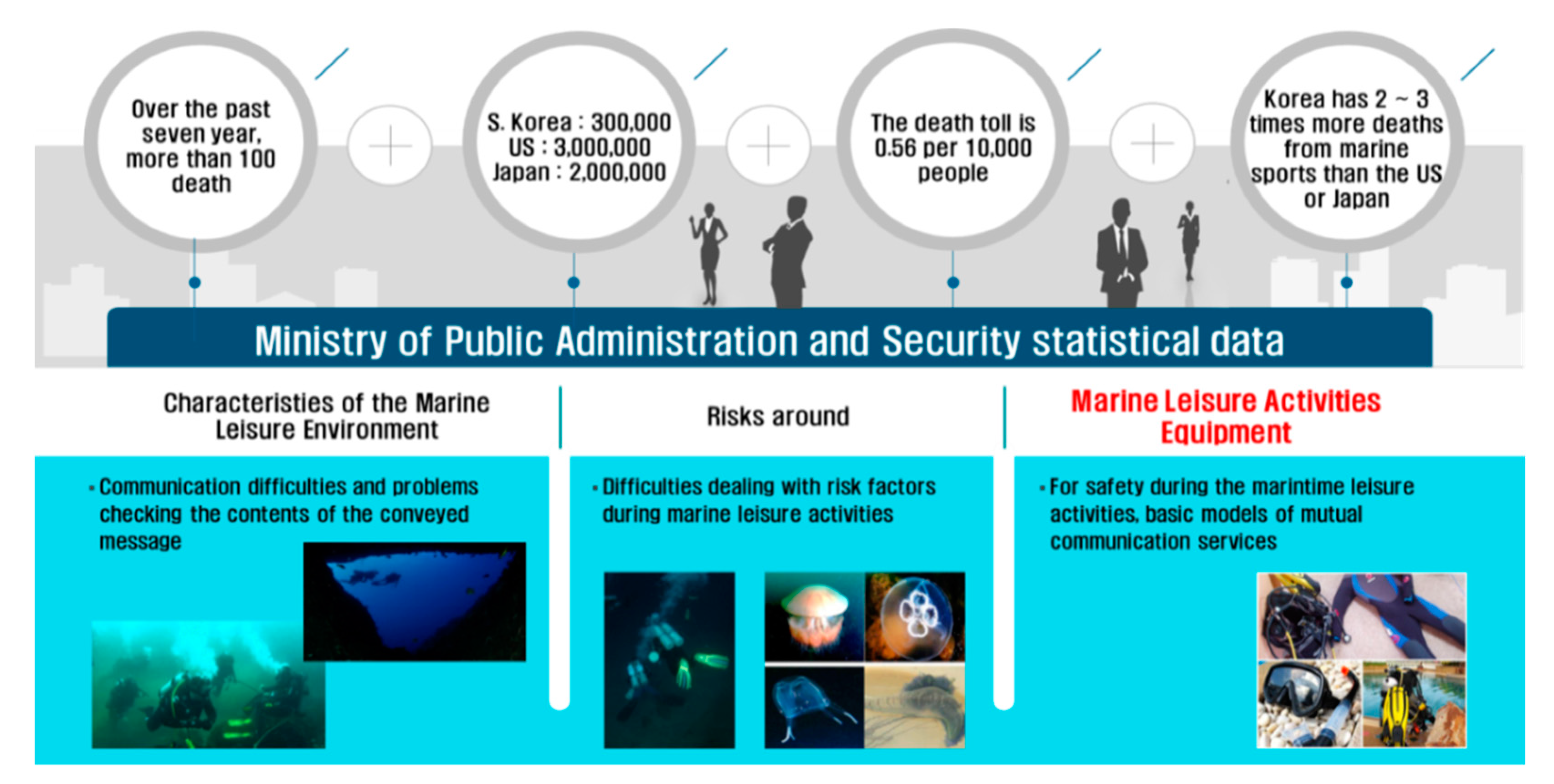
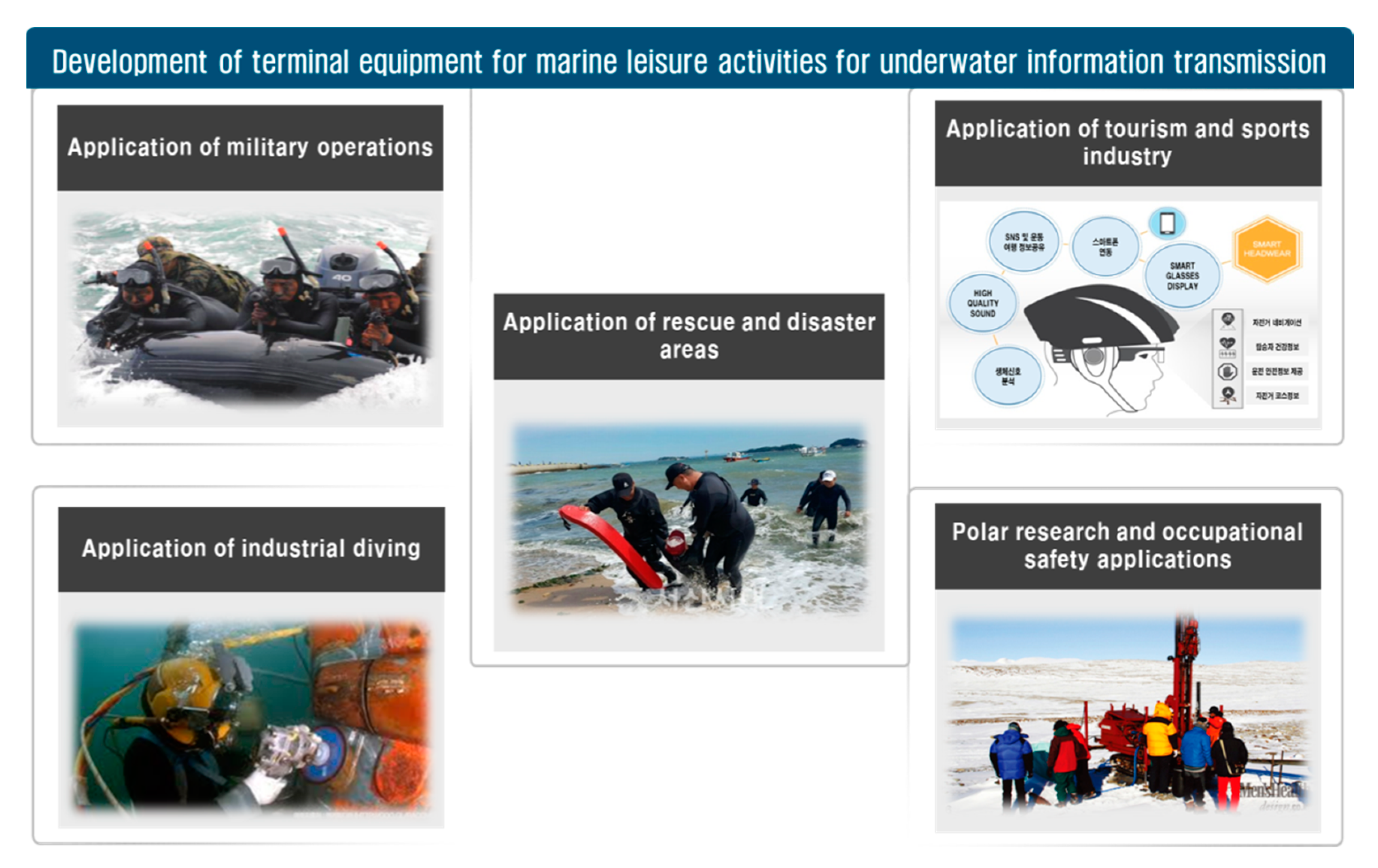
4]. As industrial development of modern society and economic affluence have led to improvement in people’s living standards, there are increasing demands for various marine leisure activities that will improve the quality of life.
Since underwater activities are not free and brain activity is reduced by breathing on air tanks, those limitations make it difficult to quickly respond to the surrounding risk factors (lack of air, dangerous marine life, and rapid algae). Therefore, a new type of dive computer is developing for marine leisure personnel to communicate underwater information [
5,
6,
7].
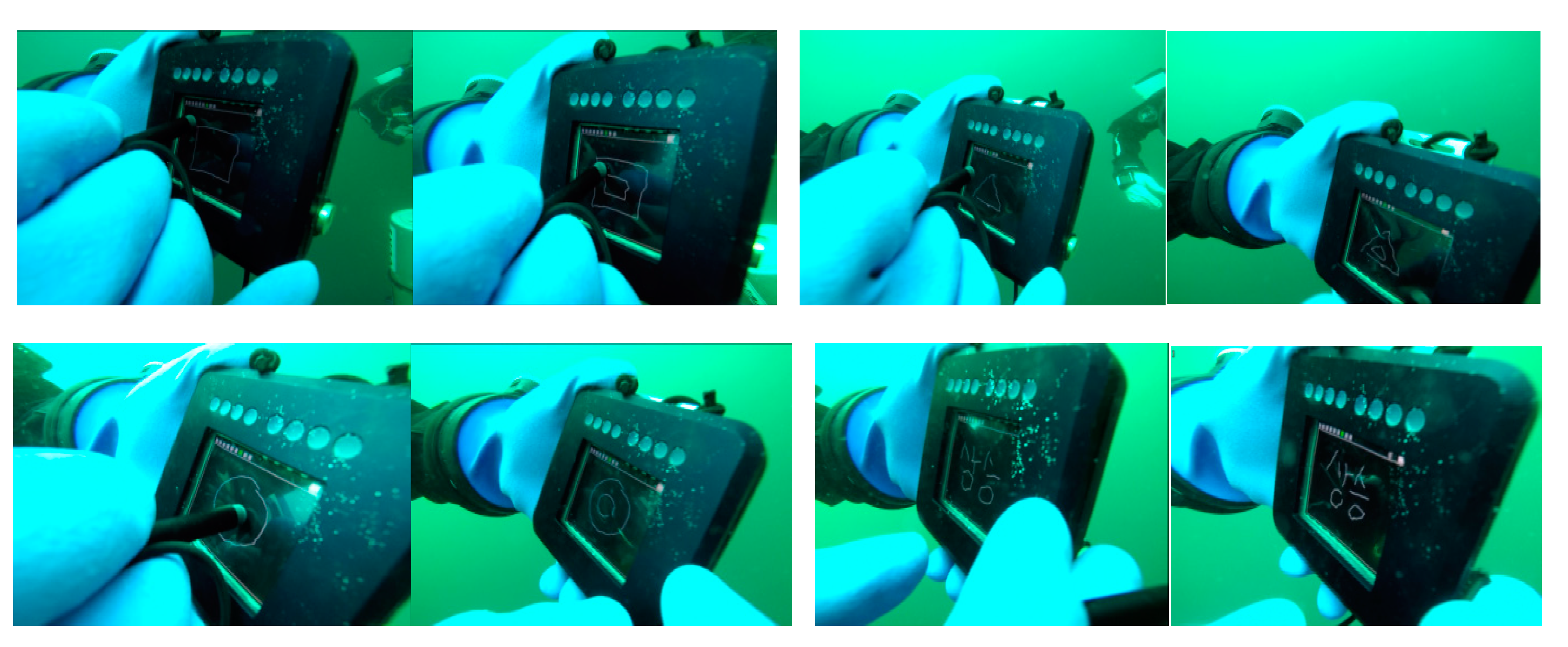
In order to communicate clear and immediate information delivery through touchscreen based user friendly interface in the water, we implemented a new underwater communication-device that can be applicable to both professionals and publics for conducting marine leisure activities. The proposed underwater communication-device can support image/text data processing, and powerful visibility on the touchscreen. While conventional dive computers support several functionalities in terms of depth of water, water temperature, time, ascent/descent excessive speed alarm, and compass, the proposed communication-device, so called DiverPAD, can provide divers with touchscreen based memo functions (drawing and writing) as well as conventional functionalities.
The remainder of this paper is organized as follows: the previous works for recent dive computers are introduced in
Section 2. The design and implementation of the proposed DiverPAD are described in
Section 3. Finally, field test and conclusions are presented in
Section 4 and
Section 5, respectively.
2. Previous Works
Because scuba diving, as a kind of typical marine leisure activities, has a limitation by the breathing in the water, most divers have been using the dive computer to observe underwater information [
8,
9]. In addition, divers can obtain underwater information such as diver’s location from tablet screen within a waterproof case [
10]. As depicted in
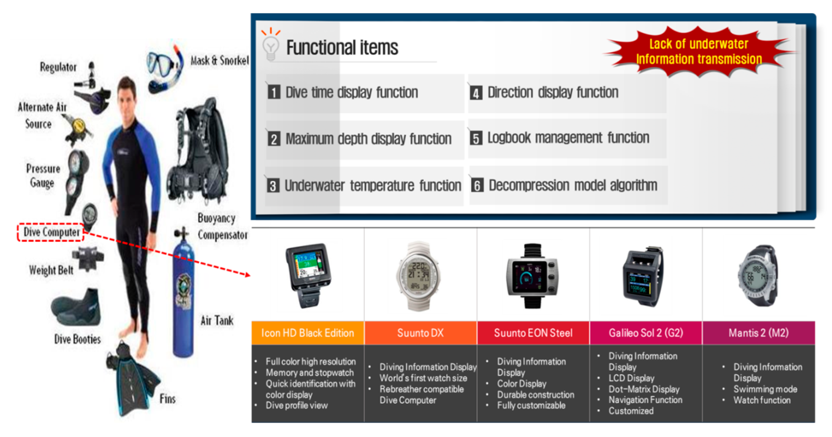
Figure 1, typical dive computers are manufactured to be worn on a human wrist and they provide a variety of underwater information about dive time, remaining air, water dive depth, and temperature. Since the information directly affects to people’s lives in an emergency, the accuracy and reliability of the information obtained by the dive computer is important factor to the divers.
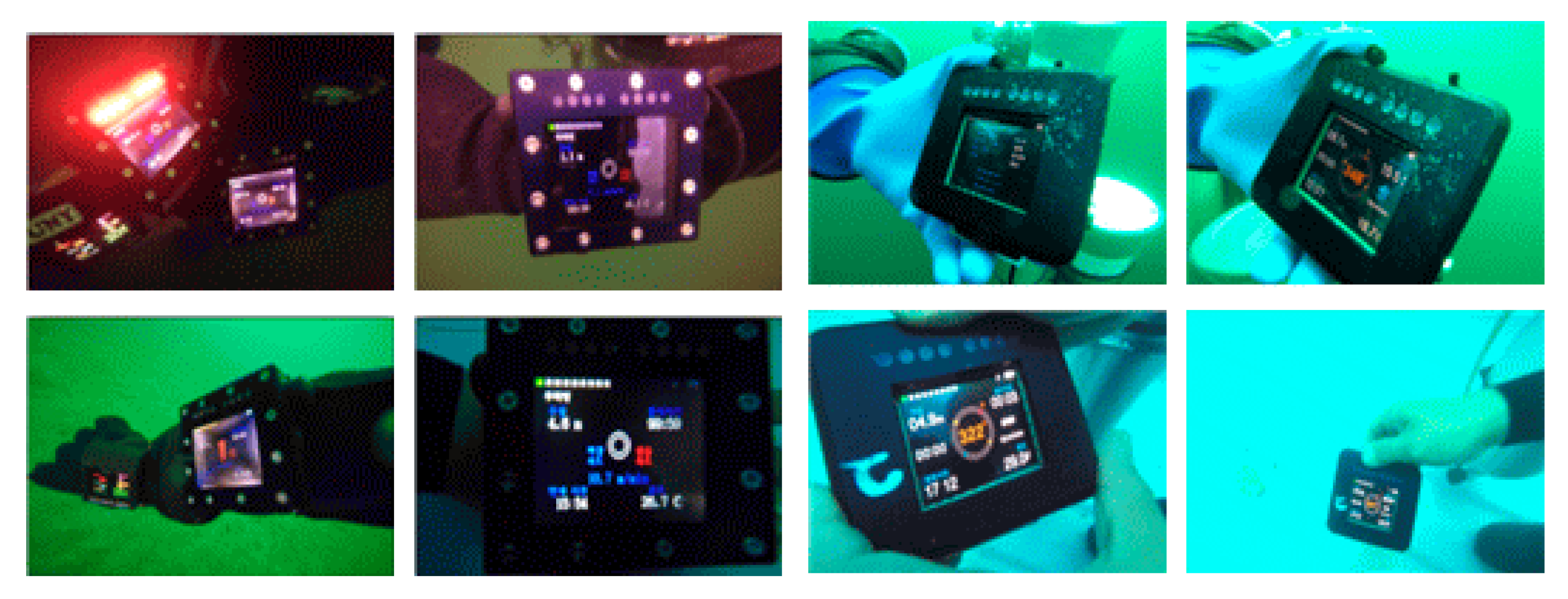
Even though conventional diver computers provide the basic information of underwater environment on display panel as shown in
Figure 2, these cannot provide efficient communication methods among divers in the water. In addition, communication methods by using hand signals or writing board have limitations in transmitting and receiving accurate information in the water. In order to communicate underwater information about emergency situations in the water, new underwater device for supporting correct communication is needed to exchange accurate underwater information in the type of touchscreen based texts, symbols, and pictures [
11].
In the case of conventional touch panels, when a point on the display screen is pressed or touched with a finger, a process to recognize the location corresponding to the pressed point works in three types, which are capacitive type, resistive film type, and infrared/ultrasonic type. Capacitive type is generally used in the conventional touch panels and it forms a constant capacitive layer on an insulating layer.
Because the weak electrical signal could not be properly detected in the water, when a finger touches a pad that is a transparent electrode on a substrate of the capacitive layer, touch signal is generated with its position. This is a difference between the existing touch panel method which detect the static signal and the proposed method to detect the weak electrical signal from the finger.
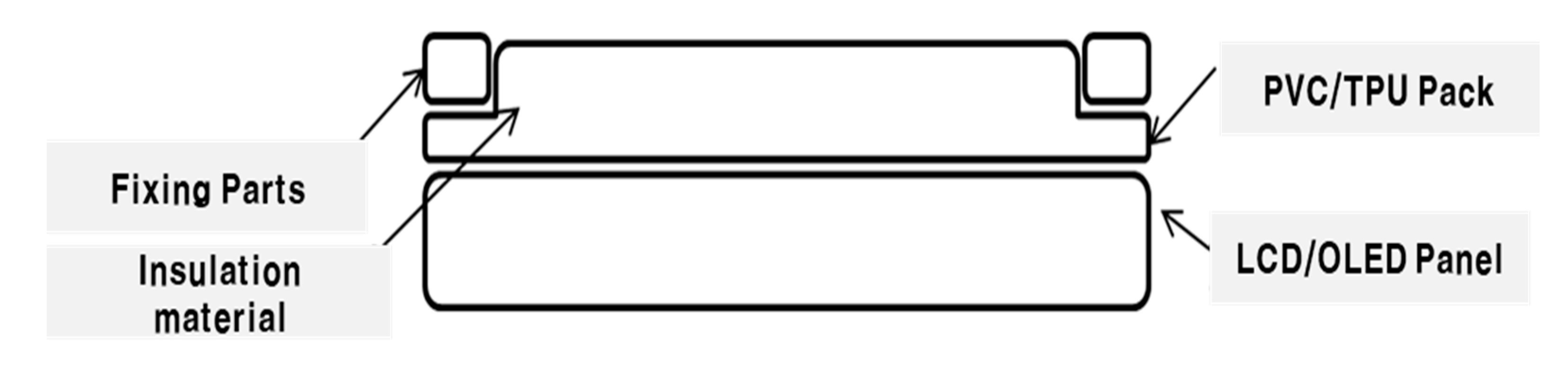
In this paper, DiverPAD was implemented with the capacitive method to enhance the correctness of electrical signal during marine leisure activities as shown in
Figure 3.
The PVC (Poly vinyl chloride)/TPU (Thermo Plastic Polyurethane) of
Figure 3 is a material that is less corrosive and resistant to chemicals and it has the characteristics of generating static electricity. Since it has the characteristics of plastic, it can protect the touch panel from sea water and it is possible to transfer the user’s touch input to the LCD (Liquid Crystal Display)/OLED (Organic Light Emitting Diode) panel by inducing static electricity. Inside the PVC/TPU, an insulating material, so called glucerine, was filled to allow smooth touch input.
3. Proposed Wrist-Mounted Dive Computer for Underwater Drawing and Writing First Bullet
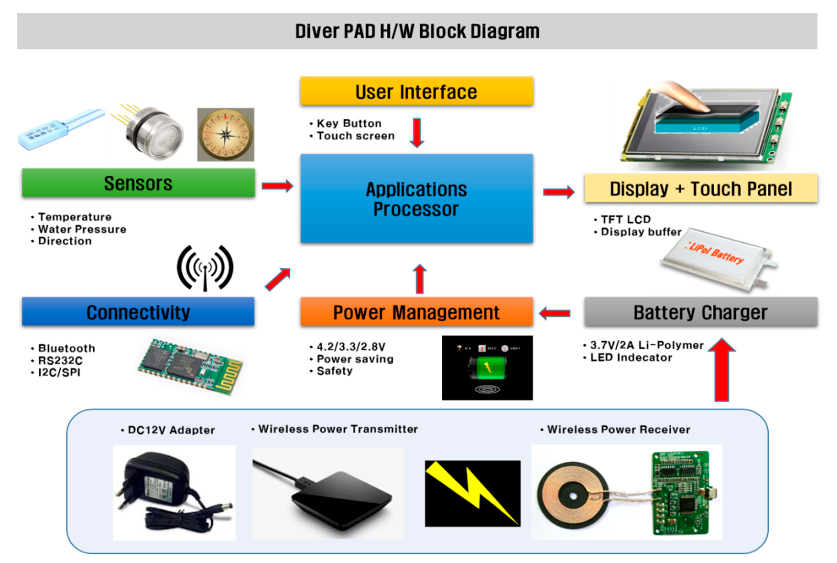
The proposed DiverPAD are composed of applications processor (AP), battery charger, power management, display, sensors, and Bluetooth based connectivity modules as depicted in
Figure 4. While DiverPAD can provide the functions of conventional dive computers, its main feature enables to provide the function of underwater drawing. Therefore, DiverPAD was newly modified on four major modules for supporting the underwater drawing, which are firmware, protocol, user interface, and underwater touch screen.
In addition, we set DiverPAD’s target values in terms of supply voltage, operating time, operating temperature range, waterproof depth, charging time, and battery capacity to ensure drawing capabilities as well as existing conventional functions as described in
Table 1.
3.1. Firmware
There are three main operations in terms of firmware in DiverPAD as followings: First, it prescribes the specific module code that makes up the hardware. Second, it controls the user interface (UI) for terminal device operation. Lastly, it stores user data (sensor, text, and image data).
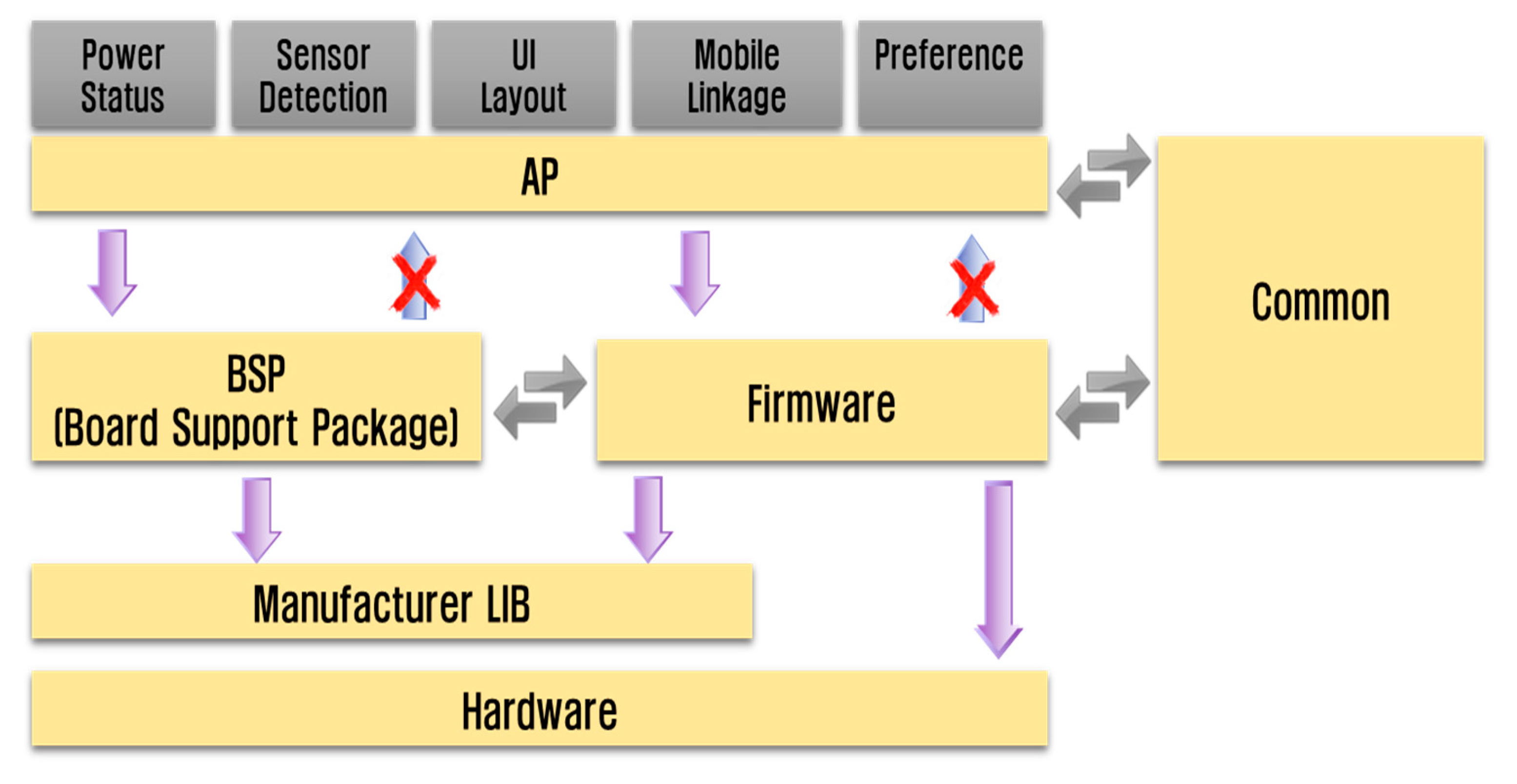
As depicted in
Figure 5, DiverPAD’s firmware is installed into the main controller and it is combined with power status information, sensor detection, screen configuration, mobile linkage, and environment setting to maintain function-based calling relationship. After the initializations of each module is performed, DiverPAD operates specific functions like drawing according to “DiverPADTask” as presented in Algorithm 1, which is obtained from the touch panel by pressing the touch pen. As the insulator came into the reservoir space, upper and lower layers contact. Following this, the touch panel unit recognizes the point of contact and performs the drawing and writing process. When the user releases the touch, the restoring force raises the upper layer, as a result the insulator flows back from the reservoir space to the touch space and returns to its original state.
| Algorithm 1 DiverPAD firmware logic | |
| Input: positive integer button, positive integer user
| |
| Output: Action
| |
1: Initialize MCU(). | // Initialize the device |
2: PowerInit(). | // Power supply initialization |
3: PowerEnableAll(). | // Power supply |
4: TimerInit(). | // Set Timer |
5: LEDInit(). | // Initialize LED |
6: MenuInit(). | // Menu Initial screen |
7: While (1) do | |
8: Initial_TFT_LCD(). | // Initialize LCD |
9: Setting Load(). | // Loading the setting value |
10: GUI_Load() | // Load GUI |
11: StateInit | // Initialize State |
12: | |
13: TFT_clear_screen(). | // Reset touch function |
14: GUI_system_info(). | // GUI information based sensor |
15: | |
16: If (MenuTak) | // Wait for menu |
17: Diver | // Function execution |
18: Else | |
19: PowerDisa | // Off the power |
20: end while | |
21: Return action. | |
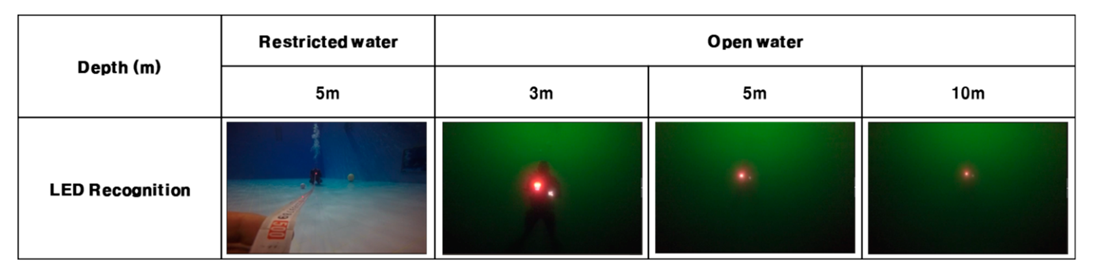
In addition, DiverPAD has eight supplementary LEDs as a means of emergency indications which are a real-time clock for dive time, a booster circuit, a switch module for various menu operations, a boot loader for firmware update, and a watchdog timer to prevent malfunction. Depending on the level of training of underwater activities, when the depth and time limit of each individual is exceeded, the LED module provides a notification function to the diver as presented in Algorithm 2. After the LED module was implemented in the form of firmware, we conducted the field tests of LED recognitions in both restricted and open waters. It can be seen that the LED brightness is high within 10 meters as shown in
Figure 6.
| Algorithm 2 dive qualification method |
Input: positive integer User, integer depth, positive integer count
positive integer clock, char cert
Output: LED alarm 1: if (count < 5) then 2: DiverRight <- beginner. 3: if (depth > 18 m) then 4: LED = Warning (RED). 5: Else 6: LED = Warning (Green) 7: Else 8: if count is positive, then DiverRight = Openwater; Advenced; Rescue; Master; 9: Return DiverRight. 10: 11: switch (clock) 12: case (9 < clock < 18) 13: LED = Warning (Green) 14: if (clock > 18) 15: if (user = cert) 16: LED = Warning (Green) 17: Else 18: LED = Warning (RED) 19: Return LED alarm. |
3.2. Communication Protocol
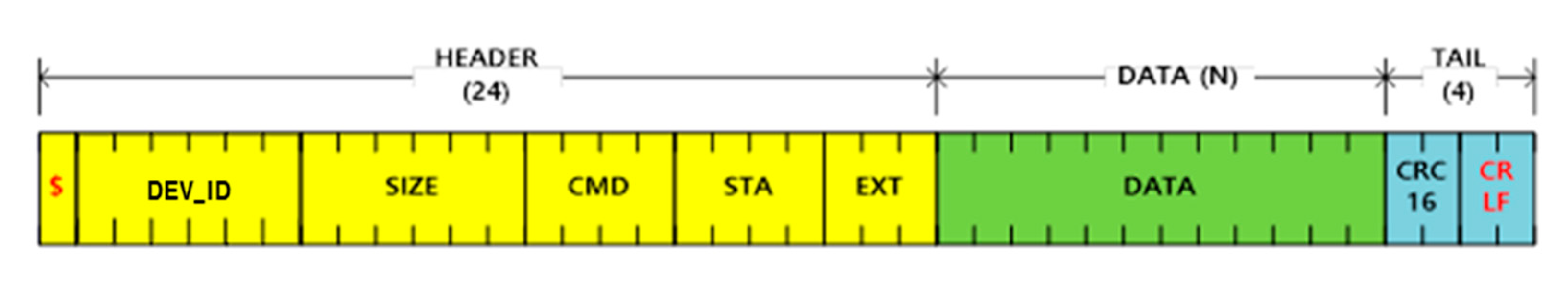
DiverPAD allows diver to store text or image data in the water. In order to communicate those data from DiverPAD to handheld devices (e.g., smartphone), we present a communication protocol for DiverPAD, which is shown in
Figure 7. Since the communication function is not smooth in water, an optimization method for fast and accurate information transmission was implemented based on the existing communication standards.
As shown in
Table 2, some fields of the header and tail are defined as constant values in the data packet of the DiverPAD and are designed to transmit text and image data in addition to the existing sensor data.
Based on the presented data packet structure, the bidirectional communication between the DiverPAD and a handheld device is performed, and both the sensor information generated in the water and the information about the diver’s marine leisure activity are transmitted into a handheld device. In particular, as shown in
Table 3, CMD (Command) values in the packet structure are newly proposed in this paper to implement user message transmission about log data request, environment information setting, and data transmission of the DiverPAD (sensor information, text, image), so as to overcome the limitation of DiverPAD’s memory capacity.
3.3. Design of User Interface (UI)
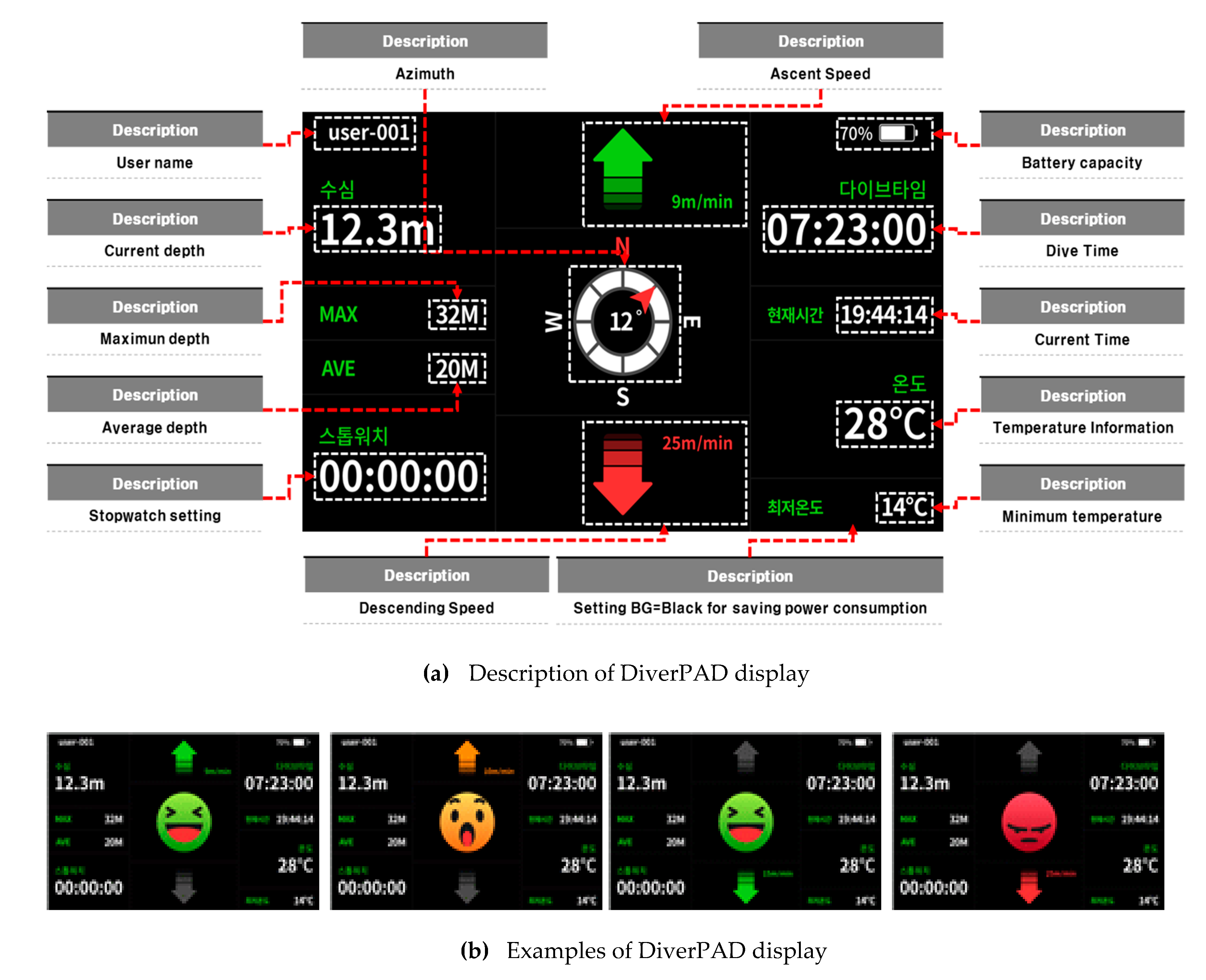
As shown in
Figure 8a, we show user environment, hardware environment, content management, and technical constraints by applying the UI design process. After wearing the DiverPAD, as a way to recognize the risk situation between marine leisure personnel, the depth and time were set according to the qualification situation, the number of times, and the curriculum. In case of increasing and descending, the update cycle for perceiving the risk situation was set in 1 s increments. The averages of previous unit time (10 s) section and the current unit time (10 s) section were analyzed.
As shown in
Figure 8b, if the difference between the maximum and minimum depth for 1 min is within 3 m, the average depth value for the 1 min section is set as the current depth, and if it is within +2~−2 m from the current depth, the swim is displayed. In addition, when a difference in water depth of +2~−2 m or more occurs in the current depth, it is displayed increasing or descending, and when a difference of +10~−10 m or more occurs, a risk situation display screen is designed and implemented.
The above pattern analysis of marine leisure activity is divided into education, emotion, and emergency modes. First, in the education mode, the educational contents of divers are stored based on the water depth and displayed according to the rise and fall. In the emotion mode, the user displays self-written contents using the terminal device buttons. The emergency mode is activated if the control system determines the situation to be an emergency, sending emergency signals to the display. The module was implemented to identify any emergencies by comparing the values using an acceleration sensor, timer, and others. The above emergency situation information (maximum depth, dive time, water temperature, rise alert and visual, nap time, date, time, frequency, and others) is compared with the values of the sensor values and database thresholds.
3.4. Electrical Insulator Based Capacitive Touchscreen
DiverPAD adopted novel underwater touch function to conveniently communicate various information among divers in the water. The touch function of DiverPAD was designed as a means of the accurate and immediate communication tools in the process of data sending and receiving. The module to operate underwater touch function consists of touch panel unit and touch input controller. In general, touch function makes it possible to detect the force of touch pen pressing on the surface of LCD or OLED panel.
In this paper, underwater touch function of DiverPAD was implemented to adaptively adjust the force of touch pen pressing according to depth of water. DiverPAD allows a user to freely express intention by inputting through a touch input underwater. Thus, a touch input diver pad comprising a module is configured so that a sensor measurement module having a temperature sensor for sensing underwater temperature and a depth sensor for detecting water depth, as well as touch input and output modules including a touch panel section displaying data by the sensor unit, a battery module for supplying power and control was obtained.
The pressure protection module is made of tempered glass and it is made as thin as possible to lighten the weight and sharpen the design defined as shown in
Figure 9.
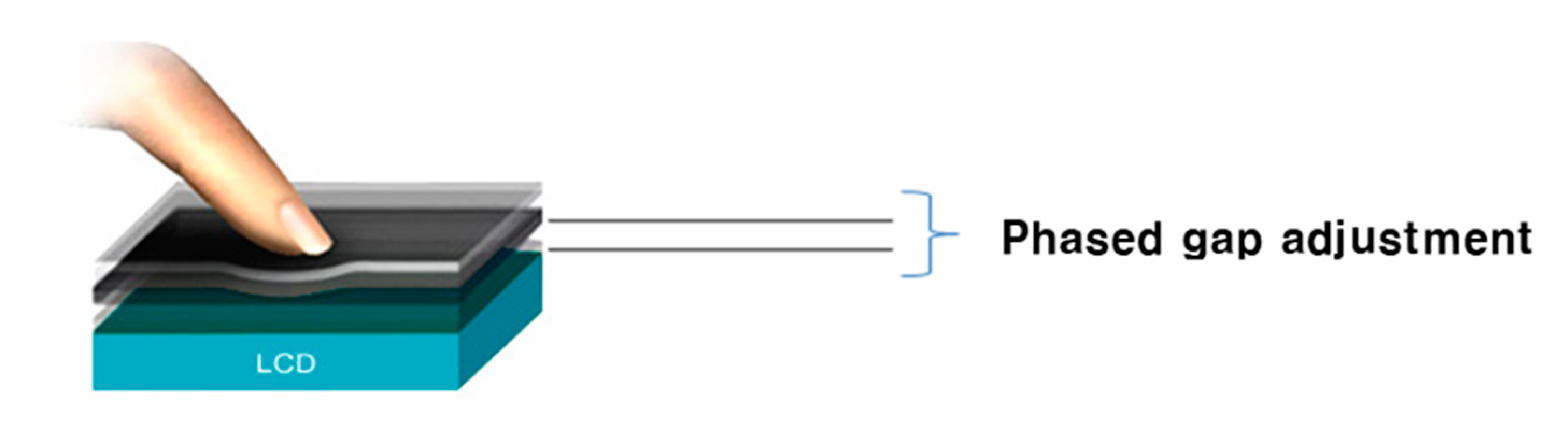
At the end of the touch input and output modules, a sealing module was installed to prevent the inflow of water and an insulated touch module was attached to the top due to unpredictable water flow and strong pressure of surrounding environment. In addition, the insulation touch module was configured to include an insulating layer between the upper layer and the lower layer as a pressure protection section. Accordingly, when there is no user’s touch in the water, the upper layer and the lower layer are separated by the insulating layer so that no touch occurs.
The insulating layer is configured to serve to prevent malfunction of the touch panel unit due to water pressure in water. Based on this, the upper part of the DiverPAD terminal device was divided into an insulation touch module, and a space division divided into a touch space and a reservoir space, so that an empty chamber was formed between the space division and the insulation touch module. In this state, when the user presses and touches the touch space, the insulator is pushed to the reservoir space, and the upper layer and the lower layer come into contact.
The touch panel module senses the point of contact, and thus touch sensing is performed. In addition, when the user releases the touch, the upper layer rises due to the restoring force, and the insulator flows back from the reservoir space to the touch space and returns to the original state.
A method of attaching an adhesive film to improve durability against external pressure was used between the thin film display module and the touch panel module and between the touch panel module and the pressure protection module. The pressure protection module includes a pair of tempered glass, and is configured to withstand strong water pressure by configuring a pressure regulating gas to be injected between the pair of tempered glass. The weight can be reduced by excluding thick tempered glass to prepare for high pressure, and it is possible to prevent fogging inside due to low water temperature due to the external environment and the role of an intermediate buffer layer inside the body.
Based on this, it is possible to conveniently and freely input the contents of the person’s intention during underwater leisure activities and to facilitate communication with the other party.


