Abstract
Leakage of information in power line communication (PLC) networks is a threat to privacy and security. A way to enhance security is to encode the transmitted information with the use of a secret key. If the communication channel exhibits common characteristics at both ends and these are unknown to a potential eavesdropper, then it is possible to locally generate a common secret key at the two communication ends without the need for sharing it through the broadcast channel. This is known as physical layer key generation. To this aim, known techniques have been developed exploiting the transfer function of symmetric channels. However, the PLC channel is in general not symmetric, but just reciprocal. Therefore, in this paper, we first analyze the characteristics of the channel to verify whether physical layer key generation can be implemented. Then, we propose two novel methods that exploit the reciprocity of the PLC channel to generate common information by the two intended users. This information is processed through different quantization techniques to generate secret keys locally. To assess the security of the generated keys, we analyze the spatial correlation of PLC channels. This allows verifying whether the eavesdropper’s channels are weakly correlated with the intended users’ channel. Consequently, it is found that the information leaked to a possible eavesdropper has very low correlation to the locally generated key. The analysis and proposed methods are validated on a measurement dataset.
1. Introduction
Information in networks where the communication means is shared is always at risk, since both authorized and illegitimate users are given physical access to the network. Malicious users have therefore a chance to jeopardize the privacy of other users or, conversely, to send false information throughout the network. Typical examples of networks where such risk is particularly threatening are wireless networks and power line networks (PLNs).
In such physical broadcast (PB) networks, as opposed to classical computer networks, a malicious user can perform attacks on all the stacks of the ISO/OSImodel, including the MAC and physical layer []. In particular, the physical layer (PHY) comes to play an important role in both planning attacks on the network and defensive strategies. In fact, since the physical medium is shared, every input into the network has an effect on the system outputs. If the network system can be modeled, then its properties can be used with both malicious or aiding intent.
The wireless community has extensively relied on the properties of the physical channel to pursue research and identify methods for information security. From an information theoretic point of view, it is possible to guarantee secure transmission when the intended communication channel has higher capacity than the eavesdropper one, by transmitting information at a sufficiently high rate []. However, some eavesdropper channels might have higher capacity than the intended one. For this reason, different techniques to enhance security have been conceived of in the communication theory area, which include secret key generation, prefiltering, and coding techniques [,,]. These techniques rely on different properties of the wireless communication channels to restrict the information leakage to any possible unauthorized receiver. Such properties include the channel randomness both in the time and in the frequency domain and, especially in time-division duplexing systems, its symmetry. In fact, if the channel between two users is symmetric, the randomness of the channel is common to the two users, i.e., they have access to the same information. This property is particularly useful for the secret key generation techniques. The key generation process includes the common information, which is unknown to an eventual eavesdropper, thus drastically enhancing the security of the produced key.
On the other side, in the context of power line transmission and distribution networks, attacks and defensive strategies are normally based on system theory. In this case, the network is modeled as a dynamic system that describes the power flow. Attacks of different kinds aim at altering the perception of the state of the network, which in turn might bring about a network failure []. In any case, informative signals need to circulate through the network; therefore, a resilient communication architecture would enhance the PLN security. However, to our knowledge, there is very limited literature about physical layer secure communications in PLNs, and it focuses almost exclusively on information theoretic analysis [,,,].
In this regard, Power Line Communications (PLC) is a well established communication technology in PLNs []. This technology already provides a form of security by the fact that it uses a communication means, the power line cables, that is owned by the utility and therefore not accessible by everybody. However, an unauthorized user might be able to get physical access to the network (see Figure 1), or the utility might not want to share some information with part of the network users. Therefore, additional security measures have to be provided. Since the PLC physical channel has some properties in common with the wireless channel, it makes sense to explore physical layer security (PLS) techniques developed for wireless communication in the case of PLC. Nevertheless, it has been shown that the PLC channel, opposite the wireless one, is rather deterministic and in general not symmetric [,], and moreover, it has different statistical properties [].
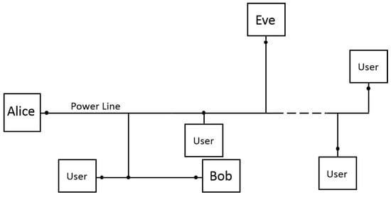
Figure 1.
Essential sketch of a power line network, where we highlight the presence of the transmitting user (Alice), the intended receiver (Bob), and the eavesdropper (Eve).
A few recent contributions have considered the application of physical layer key generation techniques in PLC [,]. The authors propose to generate keys based on a quantized version of the frequency response of the channel, assuming a high symmetry of the channel. The assumption is supported by some measurement results, but the coupling method used is not thoroughly presented. In the following, we will show that the coupler, or better the equivalent impedance of the modem, has a crucial importance in determining the symmetry of the PLC channel. It turns out that the couplers used for half-duplex PLC lead to asymmetrical channels.
In this paper, we propose a thorough analysis of the properties of the PLC channel in order to investigate under what conditions PLS techniques, which exploit common information at the two legitimate users, developed for wireless communications apply also to PLC. However, since the PLC channel is in general non-symmetric, most of the known PLS algorithms cannot be applied to it. In fact, to the authors’ knowledge, very limited work exists on PLS in non-symmetric channels [].
In order to overcome this limit, we make use of the fact that the PLC channel is reciprocal to investigate what channel state information (CSI) is known to two legitimate users independently of each other at any given time. In this context, we propose two new methods to retrieve common CSI. The first method involves the analysis of the multipath signal propagation in reciprocal channels. The second method relies on the exchange of a minimal amount of information between the two ends, which is however insufficient for a possible eavesdropper to decrypt the key. The CSI obtained with the proposed methods can be consequently used to generate cryptographic keys separately at the two communication ends. For this purpose, we process the CSI with various quantization techniques and show the reliability of the generated keys. We also analyze the spatial correlation in PLNs, in order to verify the level of security of the obtained CSI against possible eavesdroppers. Although our investigation focuses on PLN, the proposed CSI retrieval methods are common to every reciprocal network, including any kind of passive wired and wireless network.
The rest of the paper is organized as follows. In Section 2, we briefly summarize the classical approach to PLS, which relies on the symmetry of the channel. In Section 3, we analyze in what cases the PLC channel can be considered symmetric. The two algorithms for PLS in asymmetric (but reciprocal) channels are proposed in Section 4, while extended results are presented in Section 5. Conclusions follow in Section 6.
2. Channel-Based Security Approaches in Symmetric Channels
Most of the PHY key generation techniques, especially the channel-based ones, rely on the symmetry of the channel [], i.e., the fact that for every set of currents and voltages at the two communication ends that satisfies a certain system of relations, the set obtained by exchanging the transmitter and the receiver satisfies the same relations. In short, this means that the CSI is identical for both links. Wireless channels are typical examples of symmetric channels.
In this paper, we model the transmitter with its Thevenin or Norton equivalent with transmit impedance and the receiver with its receive impedance . Moreover, we considerthe physical channel to be a system accessible in two ports, Port 1 and Port 2, where the transmitter and the receiver are attached (see Figure 2). The channel transfer functions (CTFs) and defined as (We remark that Equation (1) and the rest of the equations presented in this paper are a function of the frequency. This dependency is omitted in the notation for simplicity.):
where is the generated voltage at the transmitter and is the measured voltage at the receiver (see Figure 2), which are equal in symmetric channels. Therefore, when the receiver estimates for example of the forward link, it directly knows also of the reverse link, without the need for further communication (The wireless literature often refers to this property as due to the reciprocity of the channel. This is technically incorrect, because in reciprocal networks, the CTF is not forcefully the same in the two directions. Although the wireless channel is indeed reciprocal, it is also in most of the cases symmetric, as we will explain in Section 4). Such a property serves as source of common randomness from which the parties can generate secret keys. An eavesdropper is assumed, at least in the wireless context, to experience a physical channel that is independent of that of the legitimate users. Therefore, the generated keys are intrinsically secure. As we will show in Section 3 and Section 4, neither the channel symmetry, nor the independence of the eavesdropper are common in PLC, which brings the problem of finding other sources of common randomness. In the following, we name the two legitimate parties Alice (A) and Bob (B), respectively, and we name the eavesdropper Eve (E). We also assume that Eve is a passive attacker, i.e., she just overhears the channel.
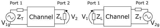
Figure 2.
Traditional communication scheme, with the generator either on Port 1 or on Port 2.
The basic idea of channel-based key generation approaches is for Alice and Bob to obtain very correlated information from the channel via channel training, then to apply key generation methods that rely on the correlated information and public discussion []. From an information-theoretic perspective, the key generation procedure can be described as follows:
- Channel sensing: Alice, Bob, and Eve get the observations of length n of the CSI , , and , respectively, where the observations can be performed in the time, frequency, or space domain or a combination of them.
- Key reconciliation via public discussion: In order to agree on a secret key, Alice and Bob can communicate through the PB channel and send to each other a deterministic communication sequence as follows. They generate the random variables and , respectively, for initialization. Then, they alternatively send to each other the two sequences and , respectively, where for each step i, we have and . At the end of the communication step, Alice and Bob determine the respective keys as and . Different protocols have been proposed to implement both the reconciliation procedure, implemented either with cascade or error correcting codes, and the privacy amplification. An extended series of references about this can be found in [].
By definition [], a secret key rate is achievable if for every and sufficiently large n, there exists a public communication strategy such that:
where and denote the entropy and mutual information operators and is the key alphabet. Equation (2a) means that and are equal; Equation (2b) ensures that no information is leaked to Eve; Equation (2c) grants a minimum key generation rate ; and Equation (2d) indicates that the generated key is uniformly distributed. It is clear from Equation (2) that the possibility of generating at least one or multiple keys is based on three characteristics of the PB medium: the temporal variation (i.e., the randomness), the correlation of the CSI between Alice and Bob, and the spatial decorrelation of Eve. These three characteristics are fulfilled in many wireless scenarios, where the channel varies frequently, it is symmetric, and the users typically experience uncorrelated multipath fading. This practically means, respectively, that n (considering observations in time) is low, and are very correlated, which guarantees a fast convergence for the condition Equation (2a), and they are both uncorrelated with , which guarantees the convergence of Equation (2b).
In the following, we analyze how the characteristics of the power line medium can be used to retrieve highly correlated CSI among Alice and Bob. Moreover, we discuss the physical constraints that limit the achievable in PLN. Considering the system model introduced in Figure 2, we assume Alice to be branched at Port 1 and Bob or Eve to be branched at Port 2, depending on which CTF is of interest.
3. Symmetries of the Power Line Channel
In this section, we present under which conditions the power line channel is symmetric. Under these conditions, the existing PLS techniques developed for wireless communications can be similarly applied to PLNs.
It has been shown in [] that the power line channel is symmetric, with reference to the classical voltage transfer functions as in Equation (1), if the output impedance at the transmission side is equal to the load impedance (see Figure 2). Similarly, this condition applies to the wireless channel and to any other kinds of passive networks. However, while in wireless systems, both and are set to the same value (usually 50) to maximize the power transmitted and received, the situation is different in PLC.
In classical half-duplex PLC systems, the maximum communication rate is obtained by maximizing the transferred voltage or, more in general, the SNR at the receiver []. Therefore, PLMs are usually equipped with , k, and a switch that selects the correct impedance based on the link status []. This renders the channel highly non-symmetric.
In the recently proposed full-duplex PLC systems, some front-end transceiver architectures deploy circulators []. Thanks to these devices, the output and the receiving impedances at a single port can be tuned to be the same. Consequently, if the two communication ends are equipped with similar modems, we have , and the channel is symmetric.
A third communication architecture, which has not yet been proposed in the context of PLC, can be considered. It relies on the fact that the PLC channel is reciprocal [] to get symmetric CSI. What is symmetric in this case is not the voltage transfer function as in the full-duplex one, but the trans-impedance Equation (3) or from the trans-admittance Equation (4), as explained below. In fact, in any reciprocal two-port network, the following holds true []:
- When the current is applied to any of the two ports, the open circuit voltage measured at the other port is the same. Referring to Figure 3a, this means that the ratios:obtained when the two ports are inverted, are equal under the condition .
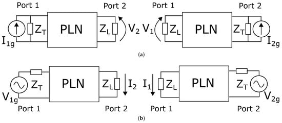 Figure 3. Trans-resistance (a) and trans-conductance (b) communication schemes in a power line network (PLN), with the generator either on Port 1 or on Port 2.
 - When the voltage is applied to any of the two ports, the short circuit current measured at the other port is the same. Referring to Figure 3b, this means that the ratio:obtained when the two ports are inverted is equal under the condition that .
Therefore, it is possible to obtain symmetric transmission of signals considering the trans-impedance Z or the trans-admittance Y of the network instead of the classical voltage transfer function (see Figure 3). However, the values of the transmit and receive impedances under which this property strictly holds are ideal ( and in the Z and Y cases, respectively) and far from the common values of and .
We now consider less ideal conditions, taking the trans-impedance case as an example. We name the trans-impedance obtained from transmission from Port 2 to Port 1 and the opposite one. We also fix to k, as is usual in PLM receivers, and modify the value of . Figure 4, which was obtained from a dataset as discussed in Section 5, shows that for low values of , the trans-impedance is highly asymmetric. The symmetry increases with the value of , and when reaches k, the trans-impedance is essentially symmetric. This condition would be practically implementable in power line modems, by driving the line with a current instead of a voltage [] and using a classical voltage receiver. Even though not shown, a similar result is obtained in the trans-admittance case when and are close to or less then 1 . Implementing this solution in power line modems would imply sending a voltage signal using a classical transmitter and receiving a current signal over a very small impedance.
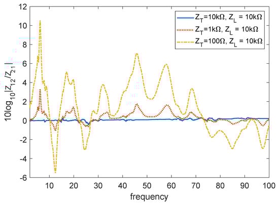
Figure 4.
Symmetry of the trans-impedance Z for different values of and .
We further consider an even more general case, where and can be fixed arbitrarily. This includes the classical case in PLC where and k. Referring to the trans-impedance case, we assume that a circuit is adopted to measure the PLN input impedance at the port k defined as:
Then, relying on the voltage and current divider equations, we can write:
for the transmission from Port 1 and Port 2, respectively. is the actual current entering the network, and is the open circuit voltage at the receiver. These two new quantities are the equivalent of the injected current and received voltage if the transmit and receive impedance would have had a value of ∞. Similarly, in the trans-admittance case, we have:
where and are the equivalent of the injected current and received voltage if the transmit and receive impedance would have had a value of zero. This means that Equations (6)–(9) allow us to reproduce the conditions for symmetry in the respective systems. In fact, the resulting trans-impedances and , as well as the trans-admittances and are respectively equal, independent of the actual values of and used.
In conclusion, a symmetrical CSI can be derived as explained above also using classical values of output and load impedances in PLMs. A possible drawback of this method is that the receiver needs to know both and . Hence, the value of or needs to be transmitted through the public channel with the risk of eavesdropping. However, a possible eavesdropper would not have access to the values of or in the trans-impedance case or or in the trans-admittance case, which is a trait of the intended receiver. Therefore, sharing information about the channel input impedance at the transmitter and at the receiver does not directly enable an eventual eavesdropper to estimate for example . This approach is further elaborated and discussed in Section 4.2, where we do not limit to trans-impedance or trans-admittance architectures, but we generalize this method to any kind of communication architecture.
4. Key Generation in Half-Duplex PLC
In this section, we propose two techniques to get common CSI at the transmitter and the receiver with minimal exchange of data. Conversely, as in the previous section, we do not assume the use of particular transceiver architectures, and we rely only on an estimation of the voltage transfer functions Equation (1) and, in Section 4.2, of the input impedance Equation (5). Since in this case, the channel is not symmetric, both techniques rely just on the fact that the PLC channel is reciprocal.
4.1. Time Domain Symmetry Technique
Considering a generic two port network, which in our case represents the PLN, the transmission matrix is defined as []:
where the subscripts 1 and 2 stand for the relative port. When the system is reciprocal, which is always the case in passive networks, the following relation holds true:
With this condition, the transmission matrix in the opposite direction becomes:
As shown in Appendix A, the time domain response of Equations (10) and (12) is not strictly symmetric, but wide-sense symmetric. This means that the multipath response of the channel is characterized by peaks that are in the same position both when the signal travels from Port 1 to Port 2 and vice versa. However, the amplitude of the peaks and their shape are in general different; thus, the PLC channel is not strictly symmetric. As an example, Figure 5 shows the frequency and time domain response of a typical PLC channel in the two communication directions. The frequency domain response is far from symmetric, even though a certain degree of correlation still exists. The wide-sense symmetry in the time domain appears clearly in Figure 5b. Even though the amplitude of the peaks in the two cases is rather different, we see that their position is the same. The mismatches are due mainly to two reasons. On the one hand, high peaks might render lower peaks that are close to undetectable. On the other hand, the peak detection algorithm and the bandwidth of the signal deeply influence the estimation of the peak presence and position.
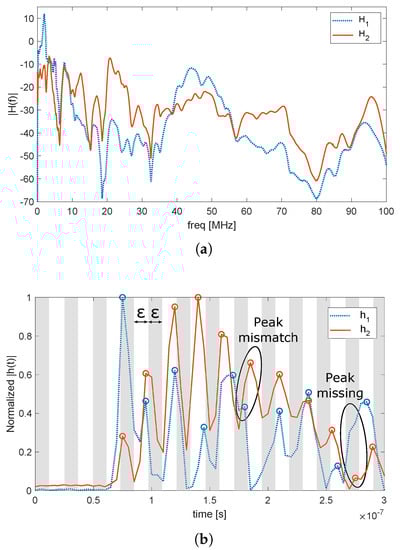
Figure 5.
Example of a power line communication (PLC) channel transfer function in the two directions, in the frequency (a) and time (b) domain.
One way to compensate these errors and to construct a key is to divide the time domain response h (or part of it) in blocks, each with duration (white and gray stripes in Figure 5b). A binary key with elements is generated at each node, with all values initially set to zero. After channel estimation and peak detection, every key element is set to one if at least one peak is detected within its time block, so that the binary key K is generated. The principle of this method is similar to that proposed in [,] for the quantization of the frequency domain response with the assumption of almost symmetrical channels. Conversely from that, however, the proposed method is valid in general for every reciprocal channel. The time domain symmetry technique (TDST) method can be further refined by limiting the peak search to the first M blocks set to one. The limit is set because, due to the multipath and the smoothing effect of the channel, the density of the peaks tends to increase, and their granularity tends to decrease with the time index, respectively. This means that every possible K would have many peaks towards the end of the sequence, which results in high similarity between different keys. Conversely, when the limit to the first M ones is applied, there are higher chances that the position of the ones in keys generated from Alice and Eve are in different positions. Finally, key reconciliation procedures, such as Slepian–Wolf coding [], can be run as presented in Section 2 to agree on the final key.
A drawback of the TDST is the generation rate of new keys, which is very low or even zero. This is because the position of the peaks in the time domain response is due to the topological structure of the network. Thus, the key would change only when a topology variation occurs. Small physical variations of the channel, due for example to its periodic time variant nature [] or to impedance changes at the terminations, do not in generally affect the presence or the position of peaks in the time domain channel response. The topology is only modified when a power switch is activated to route the power flow to a different section of the grid or when an anomaly like a fault or a strong impedance change occurs [].
In the case of transmission and medium voltage distribution networks, topological variations might occur from hours to weeks one from another. In the case of indoor or low voltage distribution networks, the topology of PLNs is fixed unless an anomaly occurs; therefore, each communication pair can generate just one code. Since frequent channel changes are needed to prevent eventual eavesdroppers to retrieve the communication key, this key generation technique is prone to be decrypted over a long time period. Increased security could be obtained, for example, by combining the TDST with classical cryptographic methods to refresh the key periodically.
4.2. Transmission Matrix Technique
Taking as a starting point the normalization procedure presented in Section 3 (see Equations (6)–(9)), we can extend it to derive the full transmission matrix of the communication link. For this purpose, we assume the power line modems to be enabled to provide an estimate of the frequency response H and of the channel input impedance , respectively [].
Since the parameters A, B, C, and D of the transmission matrix are the same in the two directions, their estimation at one communication end would enable the complete electrical characterization of the channel in both directions. Relying on Equations (1), (5), (10) and (12) we can write the following equations:
The four complex unknowns A, B, C, and D can be found by solving a system made with these four complex equations []. However, solving this system at each communication end requires information about , , , and to be shared on the PB channel. This would allow also any potential eavesdropper to solve the system, resulting in no secrecy.
On the other hand, relying on Equation (11), another system of equations can be written. Considering for example the user connected at Port 2, he/she can directly estimate , by relying on classical pilot signals used in communication systems [], and with an impedance sensor. At this point, considering also Equation (11), only one equation is missing to derive the transmission matrix. Therefore, the value of either or has to be sent through the PB channel. If, for example, the information about is shared, then the user can solve the system:
With the estimated values of the transmission matrix, the user connected at Port 2 can estimate using Equation (16). At this point, all the PLS techniques presented in Section 2 can be applied. The same procedure applies to the user connected at Port 1, with the transmission of information about .
Since with this method, the transmission matrix is estimated by both legitimate users, the key can be generated from any of the transmission matrix parameters or from a function of them. Even though some information is shared through the PB channel, a possible eavesdropper will not be able to estimate the transmission matrix correctly between the legitimate users, since it will at maximum have three equations available. When the cryptographic key is based on the degree of freedom left to the legitimate users, then the eavesdropper has no means to retrieve the key.
Regarding the estimation procedure, since , , and are constant as long as the transmission matrix is constant, their best estimates , , and are given by averaging over time, assuming zero mean noise []. , , , and , are then simply derived by directly solving Equation (17). When the channel state changes, the estimation procedure can be repeated, and a new cryptographic key is generated.
Different methods can be proposed to quantize and arrange the selected CSI. First of all, we consider the absolute value of the magnitude of the selected CSI to be linearly quantized over levels for every frequency bin. Then, we consider two ways of arranging the data:
- Binary: The quantized data are converted to binary sequences with Gray encoding to minimize the distance between symbols that are close to each other. Each binary symbol is used as a symbol of the key.
- Coded: The key is defined over an -ary alphabet, and each symbol is made by the quantized value of the CSI at one frequency bin. One symbol at the end of the key sequence accounts for the actual value of the least significant bit. The actual key is generated by multiplying the values of all the symbols by the last one. This method is used to avoid data with a similar shape, but different amplitudes to produce similar keys.
These two methods will be compared in Section 5, where we consider as an example the key to be derived from . We remark that other quantization methods are possible. However, a thorough comparison of quantization methods is out of the scope of this paper.
As mentioned before, the PLC channel is typically cyclostationary with a period equal to the main semi-circle and can be roughly subdivided into a series of slots in which it is considered static. Such intervals typically are in the order of some hundreds of microseconds []. Hence, the number of cryptographic keys that can be generated for a given node pair using the proposed method is equal to the number of time slots in the particular scenario. Since the state variations are much higher at frequencies below 5 MHz than above, a higher number of and less correlated keys are likely to be generated using narrow-band PLC, which uses the spectrum 3-500 kHz, than broad-band PLC, which uses the spectrum 2-86 MHz. Therefore, the proposed method for key generation is expected to have the best performance when applied to distribution networks, where PLC are used mainly within the narrow-band spectrum.
4.3. Computational Complexity
The computational complexity of the transmission matrix technique (TMT) method is rather straightforward to compute. We assume that, due to power allocation and equalization purposes, each PLC modem already performs the estimation of the channel impedance and the channel transfer function H. The overload due to the TMT method to get common CSI consists only of solving the system Equation (17) for the four unknown parameters.
Regarding the TDST method, we assume that the time domain response has already been estimated, via direct analysis of the incoming time domain trace or spectral analysis of the OFDM symbols. At this point, the computational complexity of this method is , if a set of N blocks is considered. However, the complexity is less than linearly proportional to M if only the first M peaks are considered since, as explained in Section 4.1, the density of peaks tends to increase with the time index.
5. Practical Results
The results presented in this paper were based on the measurement campaign presented in []. In this measurement campaign, the full transmission matrix of a total of 1312 in-home channels divided into three sites was measured in the frequency range from 0.1 to 80 MHz. We chose this dataset because, to our knowledge, it was the only one available with measurements of the full transmission matrix. However, considering the results of other measurement campaigns conducted on distribution grids [], we expected our results to be qualitatively applicable also in the outdoor scenario.
5.1. Channel Correlation
As presented in Section 2, one fundamental property to generate secure keys from the physical channel is the strong correlation between the two forward and reverse channels from Alice to Bob and vice versa. At the same time, both the Alice to Eve and Bob to Eve channels have to be correlated as little as possible w.r.t. the two legitimate channels. Therefore, in this section, we analyze the spatial correlation of PLC channels, independently of the key generation method used.
A first work presented in [] defined the space-frequency correlation as:
where i and j stand for the channel realization indexes, is the expectation operator, ℓ and m stand for the frequency bin indexes, and H is the CTF of a specific channel. The correlation is computed as an expectation over all the channels that share the same transmitter and over all the possible transmitters. The results showed that the average correlation between the channel transfer functions from or to different outlets was rather low, but it increased to values around 0.3 when the absolute values of H were considered.
In this work, especially in the case of the TMT, information about the input impedance was shared, and Eve was interested in retrieving and from it (see Section 4.2). Therefore, it is of interest to compute:
where and share the same transmitter. The results in Figure 6, where we fixed , show that was on average low, but the frequency-space correlation , computed using the absolute values, was on the other hand not negligible. Therefore, it was recommended, when generating secure keys with the TMT, to ensure the use of the estimated complex values and not just their magnitude.
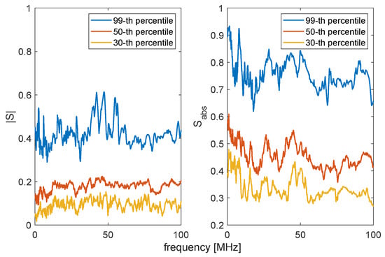
Figure 6.
Correlation between the and the CFTtransmitted from the same node.
It also makes sense to use a broader definition of correlation, which is not dependent on the frequency bin, but just on the channel realization. For this purpose, we considered the deterministic correlation coefficient , defined as:
where L is the total number of frequency bins considered. The results are plotted in Figure 7, where the left picture shows the results for and the right one shows , which is the correlation as in Equation (20) computed with the absolute value of the transfer functions. On the main diagonal, instead of plotting the autocorrelation of each channel, which would be one, we plot between the Alice to Bob and the Bob to Alice channels. The results showed that the power line channels were rather uncorrelated (left) and that the correlation increased when the absolute values of the transfer functions were considered (right). The correlation between the channels of the legitimate parties was on average higher than that with Eve, but still not significant (see Table 1).
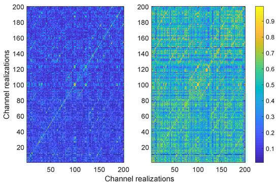
Figure 7.
Correlation coefficients (left) and (right) of the channel transfer functions for 200 channel realizations.

Table 1.
of the channel transfer function in different cases. CTF, channel transfer function.
In Figure 8, we plot computed as:
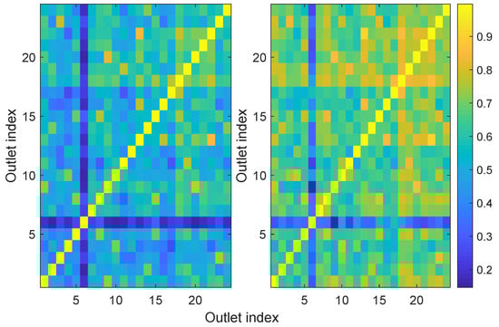
Figure 8.
Correlation coefficients (left) and (right) of the input impedances of 24 outlets in the same household.
The results showed that the input impedances were more correlated than the channel transfer functions, especially when the absolute values were considered. This might be due to the fact that the input impedance was, notably at high frequencies, very dependent on the characteristic impedance of the cable to which the modem was branched. If different outlets were branched to cables with similar characteristic impedances, then a certain degree of correlation was expected.
5.2. Time Domain Symmetry Technique Results
As presented in Section 4.1, the time domain channel transfer function was not expected to be more correlated than the frequency domain one, since h was made by peaks that had different heights in the two directions. The results when computing Equation (20) for the impulse response were similar to those obtained with the CTF. In fact, the correlation between the Alice to Bob and Bob to Alice channels was almost the same in the two cases and only with Eve the correlation was slightly lower in the impulse response case (see Table 1).
In order to localize the peaks needed to apply the TDST, we considered different spectral analysis techniques, both parametric and non-parametric []. Given the wide bandwidth available, the best results were achieved using a non-parametric technique that consisted of interpolating the original estimated time domain trace and applying the energy-based peak detection technique presented in []. The interpolation filter was a truncated sinc, which was equivalent to zero padding in the frequency domain. Although the interpolation did not reveal any more information about the presence of peaks, it greatly improved the estimation of their location.
Figure 9 shows the average of the correlation coefficient computed as:
as a function of the number M of the peaks considered, for differentamounts of interpolation points. As for the length of the key K, we set it to N = 200 elements, which were obtained by segmenting the impulse response into 200 time blocks, each with duration , where is the sampling period after interpolation. The results showed that when M increased, the correlation between the keys generated from Alice and Eve increased linearly, while the correlation coefficient between Alice and Bob almost saturated after the first steps. This prompted us to consider that high values of M for key generation might reduce the security of the key. On the other hand, using very low values of M reduced the correlation of the legitimate parties and also simplified the work needed by Eve to infer the key by a series of random guesses. This aspect is investigated in detail in Section 5.4. Concerning the interpolation, increasing the number of interpolation points slightly reduced the correlation between Alice and Bob, but drastically reduced the one with Eve. This is particularly clear in Figure 9b, which shows that the ratio between the two correlations was, for example, the same when using and no interpolation and and three point interpolation. The use of interpolation is therefore encouraged in order to generate secure keys.
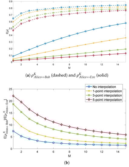
Figure 9.
Correlation R of the sequence of peaks computed by Alice, Bob, and Eve (a) and their ratios (b), considering the first M peaks.
5.3. Transmission Matrix Technique Results
As explained in Section 4.2, the TMT allowed obtaining common CSI between Alice and Bob avoiding Eve accessing it. Since the technique consisted of solving a fully determined system, possible mismatches were only due to the presence of noise. For example, higher estimation errors were expected when external electromagnetic interference impinged differently on the two communication ends. It was shown in [] that in the case of PLNs, this effect is limited. Considering for example the key to be generated from , Figure 10 depicts the difference:
where is the CTF estimated by Alice and is the one estimated by Bob in the presence of disturbances. The values of were on average in the range −25 dB to −35 dB, with one exception around 10 MHz, where higher values were shown. These higher values were due to disturbances caused by amateur radio transmissions.
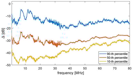
Figure 10.
Statistical distribution of in the dB scale for different frequencies.
5.4. Quantization Results
In order to assess the overall efficiency of the proposed methods, in this section, we analyze the distance d between the keys generated by the legitimate users and by Eve, using the TDST and the TMT combined with different quantization methods. We define the distance d between two keys with equal length N as:
where is the key generated by Alice and is the key generated by Bob or Eve. This definition of distance is a normalized version of the classical Hamming distance []. The two are equal in the binary case, i.e., when . When the keys are not made of binary symbols, Equation (24) ensures that the maximum distance between each symbol is one. This enables an easy comparison between different quantization methods over the same data source.
Figure 11 shows the results regarding theTDST. We notice in Figure 11a that as the number M of bins set to one increased, the average only slightly increased, and it was almost independent of the interpolation used. On the other side, the average rapidly detached from the maximum possible d, especially with low values of interpolation. These results confirmed the rapid increase in correlation with the Eve channel with increasing M shown in Section 5.2. However, the maximum possible d increases with M caused the absolute distance between the intended and the eavesdropped keys to increase, which in turn resulted in more secure keys. Regarding the results in Figure 11b, we considered all the peaks present in N blocks. We noticed that in this case, was rather influenced by the interpolation factor. This was due to the fact that, while the first few peaks in the time domain CTF were well separated and sharp, the density and the smoothness of the other peaks increased, due to the multipath and the cable attenuation. Therefore, with increasing N, there were many more less detectable peaks, which in turn increased .
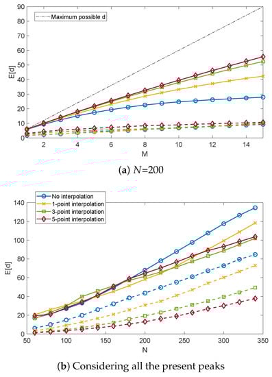
Figure 11.
for different values M of selected peaks (a) and N of the key length (b). Solid and dashed lines refer to the Alice-Eveand Alice-Bob links, respectively.
Figure 12 and Figure 13 show the resultsregarding the TMT. Figure 12a shows that, considering the same code length N, the TMT with binary symbols quantized with eight bits had a similar performance as the TDST with five point interpolation. On the other hand, the best results in terms of were achieved by the TMT coded method, although also was rather low. However, the ratio between the average and the average was maximized with this technique (see Figure 12b), which therefore ensured the best security of the key among the proposed methods.
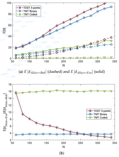
Figure 12.
of the keys computed by Alice, Bob, and Eve (a) and their ratios (b), for different code lengths N and quantization methods. The ADC resolution is fixed to eight bits.
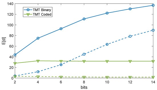
Figure 13.
of the keys computed by Alice, Bob, and Eve for different quantization bits and arranging methods, with . Solid and dashed lines refer to the Alice-Eve and Alice-Bob links, respectively.
We finally considered the effect of the number of bits used for quantization on d. As depicted in Figure 13, while increased with the number of bits in the TMT binary case, it was almost independent of it in the other case. In fact, since the CFT estimated by Alice and Bob were rather close to each other (cf. Figure 10), the same held also for the quantized values. When the number of bits increased, d for each symbol decreased, but at the same time, the number of symbols with non-null d increased, these two effects compensating each other. In the TMT binary case, on the other hand, d for each symbol could not slowly decrease towards zero, since the alphabet was binary, while the number of symbols with non-null d increased with N.
In conclusion, we found that the best results in term of average d were achieved when considering a limited number of peaks and a high interpolation factor in the case of the TDST. Regarding the TMT, the length of the key or the number of quantization levels did not play a fundamental role, but rather the method to arrange the data. Among those proposed, the TMT code yielded the best results.
6. Conclusions
In this paper, we presented different ways of enhancing physical layer security in power line networks exploiting the channel properties. On the one hand, the power line channel was symmetric when either full-duplex, transresistance, or transconductance communication architectures were used. In this case, the existing methods for physical layer security in symmetric networks, or those explicitly tailored for symmetric PLC networks, could be applied. On the other hand, when the classical half-duplex architecture was used, the power line channel was not symmetric, but just reciprocal. We showed some fundamental properties of reciprocal channels that enabled the generation of secret keys with minimal exchange of information between the two legitimate users. In particular, the wide-sense symmetry of reciprocal channels was used to propose a CSI-based key generation method that relied on peak analysis and generated highly correlated information at the two communication ends with no exchange of key information. Another CSI-based key generation method was proposed, which relied on the estimation of the transmission matrix of the link at the two ends with minimal exchange of information about it through the broadcast channel.
We also presented an analysis of the spatial correlation in power line networks based on a measurement dataset. The results showed that the power line channels had low spatial correlation, which was even lower when complex valued CSI was considered.
We finally generated secret keys by quantizing with different methods the gathered CSI and assessed their reliability by computing a specifically formulated distance between the different keys. The results showed that the distance between the keys generated by Alice and Bob was on average much lower than the distance between the keys generated by Alice and Eve. This guaranteed a good level of security of the generated keys.
This paper opens a path for new research efforts in physical layer security for reciprocal networks. Further developments might include key agreement protocols, the incorporation of other common information at the two communication ends, and the combination of the proposed techniques with classical cryptographic methods.
Author Contributions
Conceptualization, F.P. and A.M.T; validation and writing—original draft preparation, F.P.; writing—review and editing, F.P. and A.M.T. All authors have read and agreed to the published version of the manuscript.
Funding
This research received no external funding.
Conflicts of Interest
The authors declare no conflict of interest.
Appendix A. Wide-Sense Symmetry of Topology-Invariant Channels
According to the Fourier signal theory, every discrete signal X in the frequency domain can be written in the form:
where i is the frequency bin index, j is the imaginary unit, is the radiant frequency, t is the time, and is a constant. In many application cases, like for the PLC case [], the signal can be represented by the sum of K dominant exponentials as:
where the minor effects due to the other exponentials are accounted for in . In our case, X stands for either A, B, C, or D in Equation (10). The form of Equation (A2) corresponds to a series of smoothed deltas in the time domain, i.e., the inverse Fourier transform of is:
where is the inverse Fourier transform of and * is the convolution operator. The delays in Equation (A3) represent the time of arrival of each path through which the signal traveled. The values of each and can be derived from the eigenstructure of the autocorrelation matrix of , where N is the total number of considered frequency bins []. In particular, the values of , i.e., the position of the smoothed peaks, are directly derived from the eigenvectors of .
We now consider the CTF of PLC channels. Relying on Equations (14), (16) and (A2), we can write:
and:
Respectively, where is a multiplicative constant representing , , or their product. We remark that, although the coefficients are different in Equations (A4) and (A5), the exponentials are exactly the same. However, in general, and are different functions of frequency, which in time domain results in a different peak pattern for and . Nonetheless, if and are known, and can be deconvolved from the CFT. Otherwise, we remark that in practical cases, and are set to constant values over the band of interest (see Section 3). Since the two are proportional to each other, then also is proportional to . This means that and have the same propagation modes, and therefore, this holds also for Equations (A4) and (A5).
In conclusion, if and are deconvolved from Equations (A4) and (A5) or if they are proportional to each other, and have the same propagation modes and, therefore, the same sequence of delta functions in the time domain. We define this property as the wide-sense time domain symmetry of reciprocal systems. According to the Fourier theory, also and can be written in the form of Equation (A2), and since their inverse has the same propagation modes, this also holds true for and .
The wide-sense symmetry can also be explained as follows. Since the network topology is invariant in PLNs, but also in wireless networks with the assumption of a time-invariant channel, the possible signal paths between a transmitter and a receiver are fixed. When communication in the opposite direction is considered, the signal must travel the same paths, even though in a different directions and in a different order. These differences cause the signal to receive a different attenuation in the two directions. However, what does not change is the length of each of those paths. Therefore, the position of the peaks in the time domain is independent of the direction of the communication, but depends only on the position of the two modems in the network.
We remark that the wide-sense symmetry does not hold true for and . In fact, considering Equations (13) and (15), the exponential sequences of A, B, C, and D are combined through a nonlinear equation that is different for and , thus resulting in different propagation modes and peak sequences in the time domain.
References
- Zou, Y.; Zhu, J.; Wang, X.; Hanzo, L. A Survey on Wireless Security: Technical Challenges, Recent Advances, and Future Trends. Proc. IEEE 2016, 104, 1727–1765. [Google Scholar] [CrossRef]
- Shiu, Y.S.; Chang, S.Y.; Wu, H.C.; Huang, S.C.H.; Chen, H.H. Physical layer security in wireless networks: A tutorial. IEEE Wirel. Commun. 2011, 18, 66–74. [Google Scholar] [CrossRef]
- Zhang, J.; Marshall, A.; Woods, R.; Duong, T.Q. Efficient Key Generation by Exploiting Randomness From Channel Responses of Individual OFDM Subcarriers. IEEE Trans. Commun. 2016, 64, 2578–2588. [Google Scholar] [CrossRef]
- Bloch, M.; Barros, J. Physical-Layer Security: From Information Theory to Security Engineering, 1st ed.; Cambridge University Press: New York, NY, USA, 2011. [Google Scholar]
- Mo, Y.; Kim, T.H.J.; Brancik, K.; Dickinson, D.; Lee, H.; Perrig, A.; Sinopoli, B. Cyber-Physical Security of a Smart Grid Infrastructure. Proc. IEEE 2012, 100, 195–209. [Google Scholar] [CrossRef]
- Pittolo, A.; Tonello, A.M. Physical layer security in PLC networks: Achievable secrecy rate and channel effects. In Proceedings of the 2013 IEEE 17th International Symposium on Power Line Communications and Its Applications, Johannesburg, South Africa, 24–27 March 2013; pp. 273–278. [Google Scholar] [CrossRef]
- Pittolo, A.; Tonello, A.M. Physical layer security in power line communication networks: An emerging scenario, other than wireless. IET Commun. 2014, 8, 1239–1247. [Google Scholar] [CrossRef]
- Pittolo, A.; Tonello, A.M. Physical Layer Security in Power Line Communication Networks; Springer International Publishing: Berlin, Germany, 2015. [Google Scholar]
- Zhuang, Y.; Lampe, L. Physical layer security in MIMO power line communication networks. In Proceedings of the 18th IEEE International Symposium on Power Line Communications and Its Applications, Glasgow, UK, 30 March–2 April 2014; pp. 272–277. [Google Scholar] [CrossRef]
- Cano, C.; Pittolo, A.; Malone, D.; Lampe, L.; Tonello, A.M.; Dabak, A.G. State of the Art in Power Line Communications: From the Applications to the Medium. IEEE J. Sel. Areas Commun. 2016, 34, 1935–1952. [Google Scholar] [CrossRef]
- Galli, S. Exact conditions for the symmetry of a loop. IEEE Commun. Lett. 2000, 4, 307–309. [Google Scholar] [CrossRef]
- De Piante, M.; Tonello, A.M. Characteristics of the PLC channel: Reciprocity, symmetry and port decoupling for impedance matching. In Proceedings of the 2016 International Symposium on Power Line Communications and its Applications (ISPLC), Bottrop, Germany, 20–23 March 2016; pp. 93–97. [Google Scholar] [CrossRef]
- Henkel, W.; Graur, O.; Pagel, U. Wireline Physical-Layer Key Generation. In Proceedings of the 11th Workshop on Power Line Communications, Prague, Czech Republic, 21 September 2017. [Google Scholar]
- Henkel, W.; Graur, O.A.; Islam, N.S.; Pagel, U.; Manak, N.; Can, O. Reciprocity for Physical Layer Security with Wireless FDD and in Wireline Communications. In Proceedings of the 2018 IEEE Globecom Workshops (GC Wkshps), Abu Dhabi, UAE, 9–13 December 2018; pp. 1–6. [Google Scholar] [CrossRef]
- Qin, D.; Ding, Z. Exploiting Multi-Antenna Non-Reciprocal Channels for Shared Secret Key Generation. IEEE Trans. Inf. Forensics Secur. 2016, 11, 2693–2705. [Google Scholar] [CrossRef]
- Zhang, J.; Duong, T.Q.; Marshall, A.; Woods, R. Key Generation From Wireless Channels: A Review. IEEE Access 2016, 4, 614–626. [Google Scholar] [CrossRef]
- Maurer, U.M. Secret key agreement by public discussion from common information. IEEE Trans. Inf. Theory 1993, 39, 733–742. [Google Scholar] [CrossRef]
- De Piante, M.; Tonello, A.M. On Impedance Matching in a Power-Line-Communication System. IEEE Trans. Circuits Syst. II Express Briefs 2016, 63, 653–657. [Google Scholar] [CrossRef]
- ST Microelectronics. Power-Line Communication, analog Front-End; ST-PLC-AFE datasheet. 2016. Available online: https://www.st.com/resource/en/datasheet/DM00252996.pdf (accessed on 28 March 2020).
- Passerini, F.; Tonello, A.M. Adaptive Hybrid Circuit for Enhanced Echo Cancellation in Full Duplex PLC. In Proceedings of the 2018 IEEE International Symposium on Power Line Communications and its Applications (ISPLC), Manchester, UK, 8–11 April 2018; pp. 1–5. [Google Scholar]
- Pozar, D.M. Microwave Engineering, 4th ed.; John Wiley & Sons: Hoboken, NJ, USA, 2011. [Google Scholar]
- Monticelli, D.M.; Wright, M.E. A carrier current transceiver IC for data transmission over the AC power lines. IEEE J. -Solid-State Circuits 1982, 17, 1158–1165. [Google Scholar] [CrossRef]
- Corripio, F.J.C.; Arrabal, J.A.C.; del Rio, L.D.; Munoz, J.T.E. Analysis of the cyclic short-term variation of indoor power line channels. IEEE J. Sel. Areas Commun. 2006, 24, 1327–1338. [Google Scholar] [CrossRef]
- Passerini, F.; Tonello, A.M. Smart Grid Monitoring Using Power Line Modems: Effect of Anomalies on Signal Propagation. IEEE Access 2019, 7, 27302–27312. [Google Scholar] [CrossRef]
- Passerini, F.; Tonello, A.M. Analysis of High-Frequency Impedance Measurement Techniques for Power Line Network Sensing. IEEE Sens. J. 2017, 17, 7630–7640. [Google Scholar] [CrossRef]
- Piante, M.D.; Tonello, A.M. Impedance matching and channel capacity in power line communication systems. In Proceedings of the 2017 IEEE International Symposium on Power Line Communications and its Applications (ISPLC), Madrid, Spain, 3–5 April 2017; pp. 1–6. [Google Scholar] [CrossRef]
- Coleri, S.; Ergen, M.; Puri, A.; Bahai, A. Channel estimation techniques based on pilot arrangement in OFDM systems. IEEE Trans. Broadcast. 2002, 48, 223–229. [Google Scholar] [CrossRef]
- Kay, S. Fundamentals of Statistical Signal Processing - Estimation Theory; Prentice-Hall: Upper Saddle River, NJ, USA, 1993. [Google Scholar]
- Tonello, A.M.; Versolatto, F.; Pittolo, A. In-Home Power Line Communication Channel: Statistical Characterization. IEEE Trans. Commun. 2014, 62, 2096–2106. [Google Scholar] [CrossRef]
- Babic, M.; Hagenau, M.; Dostert, K.; Bausch, J. Theoretical Postulation of PLC Channel Models; the OPERA IST Integrated Project, Technical Report. 2005. Available online: http://www.ist-opera.org/opera1/downloads/ (accessed on 28 March 2020).
- Stoica, P.; Moses, R. Spectral Analysis of Signals; Pearson Prentice Hall: Upper Saddle River, NJ, USA, 2005. [Google Scholar]
- Erseghe, T.; Lorenzon, F.; Tomasin, S.; Costabeber, A.; Tenti, P. Distance measurement over PLC for dynamic grid mapping of smart micro grids. In Proceedings of the 2011 IEEE International Conference on Smart Grid Communications (SmartGridComm), Brussels, Belgium, 17–20 October 2011; pp. 487–492. [Google Scholar] [CrossRef]
- Van Lint, J.H. Introduction to Coding Theory; Springer: Berlin/Heidelberg, Germany, 1982. [Google Scholar]
© 2020 by the authors. Licensee MDPI, Basel, Switzerland. This article is an open access article distributed under the terms and conditions of the Creative Commons Attribution (CC BY) license (http://creativecommons.org/licenses/by/4.0/).