Review

Carbon-Based Composite Microwave Antennas

by
Nikolai A. Dugin
1,
Tatiana M. Zaboronkova
2,
Catherine Krafft
3,* and
Grigorii R. Belyaev
4
1
Department of Propagation of Radiowaves and Radioastronomy, N.I. Lobachevsky University of Nizhny Novgorod, 23 Gagarin Ave., Nizhny Novgorod 603950, Russia
2
Department of Nuclear Physics, R.E. Alekseev State Technical University of Nizhny Novgorod, 24 Minin St., Nizhny Novgorod 603950, Russia
3
Laboratoire de Physique des Plasmas, Ecole Polytechnique, 91128 Palaiseau CEDEX, France
4
Department of Computer Science and Telecommunications, Volga State University of Water Transport, 5a Nesterova St., Nizhny Novgorod 603950, Russia
*
Author to whom correspondence should be addressed.
Electronics 2020, 9(4), 590; https://doi.org/10.3390/electronics9040590
Submission received: 6 March 2020 / Revised: 25 March 2020 / Accepted: 25 March 2020 / Published: 31 March 2020
(This article belongs to the Special Issue Applications of Electromagnetic Waves)

Abstract

:
Applications of metamaterials to microwave antennas are reviewed over the past decade. The manufacturing of microwave antennas using graphene-containing carbon composite materials was developed and prototypes of dipole and horn antennas made from such materials were created. The radiation properties of the designed antennas and their metal analogs were measured and compared. The standing wave ratios, the radiation patterns and the amplitude-frequency characteristics were analyzed for horn antennas at frequencies 1.6 GHz and 5 GHz and for dipole antennas in the frequency range 0.2–0.6 GHz. The polarization characteristics of the horn antennas were studied. The effects of different carbon composite materials’ structures (fiber or fabric) on the antennas’ parameters were estimated. It is shown that antennas made from graphene-containing composite materials are able to operate efficiently and exhibit almost the same radiation properties as conventional metal antennas of the same geometry and size. However, the carbon-based antennas have much smaller weights and enhanced stability in a wide range of temperatures. In the future, such antennas should replace the conventional ones for many applications, especially for the excitation and reception of electromagnetic waves in space plasmas.

1. Introduction

Due to their wide domain of applications, composite materials attracted the attention of many researchers. Therefore a lot of efforts were made, including by the antenna community, to create various composite materials for industry [1,2,3,4,5]. Many works reported on the applications of composite metamaterials possessing unique properties in the microwave range 1–100 GHz [6,7,8,9]. The feasibility of left-handed materials, for which optical laws are significantly modified, was demonstrated by some authors [10]. Since pioneering works that raised much interest 50 years ago [10], different types of artificial materials were created for various applications, such as photonic crystals [11], electromagnetic band-gap [12], left-handed materials [13], graphene-containing materials [14], etc. The idea to use metamaterials in the framework of antenna technology was motivated by their ability to enhance the gain and the directivity of antennas while minimizing their size, to reduce the visibility of objects, etc. Today it is well-known that the technical designing of resonators, filters, high-gain horn antennas, transmission lines, and antenna covers is based on composite metamaterials [15,16,17,18,19,20].
As is well-known, carbon-based materials are widely used in civil industries such as, for example, in the fields of aerospace or shipbuilding. Moreover, the use of graphene-containing carbon composite materials (GCMs) in the design of antennas seems also very promising. The carbon composite materials have a long lifetime, an enhanced immunity to corrosion, the record-breaking durability-to-weight ratios, a high stability within a wide domain of temperatures [21,22]. They possess such important characteristics that they were used to create microwave antennas and antenna-feeder devices. For example, carbon materials are required for the manufacture of space, aircraft and helicopter antennas, in order to reduce their weight and to enhance their thermal expansion and their durability. The creation of composite graphene radio coatings might allow modernizing expensive radio telescopes. In this paper, an outline of recent advances concerning the carbon-based composite microwave antennas is given [23,24,25,26]. Moreover, the article includes significant new research related to dipole antennas with reflectors made from GCMs. Methods of manufacturing microwave antennas using GCMs have been developed [23] and samples of waveguides as well as microwave horn and dipole antennas were created. The radiation properties of such antennas were measured and compared with their metal analogs generally used for radio astronomical observations [24,25,26].
Therefore metamaterials can be used in various antenna systems for improving the directivity of electromagnetic waves, increasing the antennas’ gain, obtaining excellent transmitting characteristics in wide frequency ranges, suppressing interactions between the antenna elements, innovating in antenna design, and reducing the weight and the size of current antennas. Furthermore, we shall discuss in more detail the applications of GCMs in antenna and radio engineering.

2. Carbon Composite Materials in Antenna Technology

Carbon composite materials are generally used for manufacturing the parts of high-loaded structures of space antennas. For example, it was proposed to use such materials to build the supporting structures of the umbrella-type spacecraft antenna [27] for which, however, a metallized coating was required to ensure the electrical conductivity of its reflecting surface. This coating consists of metal particles or plates, which make the antenna’s radiation properties similar to those of the conventional metal prototypes [27]. A method of forming an antenna including the molding of a non-planar antenna surface with graphene coating was suggested by some authors [28]; after the graphene is coated on the antenna body, metallization, sputtering, or chemical plating is not required to ensure conductivity. It was also suggested to manufacture metamaterials consisting of concentric rings containing graphene, which have a higher conductivity than metallic components [29]. Therefore, this type of metamaterial cover suppresses the propagation loss of electromagnetic waves in antenna-fider devices.
The use of dielectric metamaterials containing graphene as elements of waveguides’ or antennas’ systems (such as inserts, corrugated structures, coatings, etc.) can improve their reflection and scattering properties [14]. Microwave transmission and reflection in multilayer composite materials consisting of cardboard, gypsum, and natural flaked graphite were studied [14,30]. The main specific characteristics of radio-absorbing materials are their thickness and the working range of the radiation wavelengths. Composite absorbing multilayer materials for the microwave range are filled with powdered metals, graphene, ferrites, or their mixtures. These absorbers may be manufactured in different forms as layers, columns, pyramids, and other complicated structures [31]. Cardboard was used as an outer layer (with the effective dielectric permittivity ε e f f = 1.5 ) that ensured the matching to free space. A minimum coefficient of reflection and transmission was observed for the four-layer samples with partly oriented graphite flakes, aimed at increasing the absorption coefficients of materials. The results obtained by some authors [14] showed the possibility to create effective radio-absorbing materials and coatings based on carbon composite materials widely used in the civil industry.
A model of gap-mode waveguide, which is a type of conductive tubular electromagnetic waveguide operating within the frequency range 1 GHz–10 THz, was proposed [32], for which the absorber provides a low-loss and low-dispersion propagation signal and improves the mechanical characteristics. It was stressed that anisotropic conductor walls (including organic conductors, graphene, carbon nanotubes) may have a specific conductivity in the direction of wave propagation [32]. Considering the polarization properties of the GCM in the microwave range [33], it was found that, when the GCM thin plate was rotated by 90 ° , the ratio of the polarization coefficient to the field amplitude reached about 0.7–0.8, depending on the concentration of the binding substance in the composite material. Please note that the anisotropic properties of the artificial materials may influence on the radiation characteristics of the electromagnetic waves, including such important features as the input impedance, the radiation pattern, the antenna gain, etc. The radiation of thin strip metal antennas located on both cylindrical and plane surfaces of a uniaxial metamaterial was considered by some authors [34,35,36], and the influence of the material anisotropy on the radiation properties of these antennas was analyzed. It was shown that strip antennas located on anisotropic metamaterial slabs may have different characteristics depending on the properties of the artificial media. Therefore the anisotropy of composite materials may be used to obtain desired characteristics for composite microwave radio-technical devices.
The properties of GCMs enable their efficient use in the creation of ground-based and space-borne antenna systems and seem promising for the future antenna technologies. Despite a wide use of metamaterials in antenna techniques, little is known about the characteristics of microwave antennas made from carbon-based composite materials. As mentioned above, when using such materials for the reflectors of space antennas, their surface is covered by a material containing either metal or graphene particles (or both together) for providing electric conduction. Our recent studies have shown the possibility to use composite materials not only for manufacturing elements and coating microwave devices, but also for creating microwave waveguides [37] and antenna systems [23,24,26]. We have developed a method for creating microwave dipole and horn antennas made from a GCM [23], and have shown that such antennas exhibit almost the same characteristics as their metal analogs.
The L- and C-range horn antennas are operating at the frequencies 1.6 GHz and 5 GHz, respectively, whereas the dipole antennas operate in the lower microwave frequency range 0.2–1 GHz. Radiation properties of carbon-based antenna prototypes as the standing-wave ratio (SWR), the amplitude-frequency characteristics and the radiation pattern were measured and compared with those of their metal analogs [24,25,26]. The polarization characteristics of a GCM microwave horn antenna were studied; comparisons with a similar antenna made from metal alloys [38,39] showed that the polarization coefficient of the composite antenna was 1.5 2 times less than that of the metal analog. Polarization characteristics only exhibit differences between the GCM horn antennas and their metal analogs. The first antenna prototypes were made from a quasi-isotropic composite material. We used the carbon fiber from the brand Zoltek Panex 35 (50K) for manufacturing one prototype of composite-material-based antenna and carbon fabric for producing the second one. The carbon fabric is a plain-weave of carbon thread, with a unit cell size equal to 2 cm × 2 cm, a tensile strength of 4137 MPa and an electrical resistivity of 1.55 · 10 5   Ω m (which ranges within 10 7 10 3 Ω m for metals) [40]. To reach structural rigidity, a graphene-containing epoxy binding substance was used, i.e., an epoxy resin modified by graphene in an amount providing the necessary electrical conductivity.
Beside horn antennas, several prototypes of composite dipole antennas at 200 MHz, 600 MHz and 540 MHz were created. For the two first ones, the radiating elements (whiskers) are made from GCMs; for the third one, the reflector and both whiskers are made from GCM. For convenience, Table 1 presents the main parameters of various types of GCM antennas and of their metal analogs. More details can be found in Section 3 (dipole antennas) and Section 4 (horn antennas). Table 2 contains the mechanical properties of metal and GCM.
Thus, the carbon composite antennas have light weights, are of robust construction and low cost. The GCMs can be used as transparent, conductive and radio-absorbing coating reducing the visibility of objects by remote sensing [14]. For ground-based and space-born antenna systems, they ensure mechanical characteristics as enhanced immunity to corrosion, high strength in combination with low relative weight, high stability within wide domains of temperatures. Moreover, the GCM antennas are able to be used as receivers and transmitters of electromagnetic signals. Below we review the main properties of the dipole and horn microwave antennas made from GCMs.

3. Dipole Antennas

Two prototypes of composite dipole antennas have been realized and studied: (i) specialized antennas operating at two frequencies, 200 MHz and 600 MHz, with broad frequency bands, and (ii) standard dipole antennas operating at 540 MHz.

3.1. Specialized Dipole Antennas at 200 MHz and 600 MHz

As analogs of composite dipole antennas, we choose special metal dipoles operating at 200 MHz and 600 MHz within expanded bandwidths. A specialized composite dipole antenna operating at 600 MHz is shown in Figure 1. Due to the design features of the dipole antennas, their radiating elements (so-called whiskers) made from composite material have a metal thread for attaching to the feeder. The length of the radiating elements is half a wavelength; they are 75 cm and 25 cm long at 200 MHz and 600 MHz, respectively. The metal reflectors of the dipole prototypes and their metal analogs were the same. The insert of the whiskers of the prototypes was made from either duralumin or fluoroplastic. During its manufacturing, we used Zoltek Panex carbon fiber as well as epoxy resin modified by graphene powder as binding substance. Radiating elements were realized using either longitudinal laying or circular winding on the dielectric insert (see Figure 2).
The SWRs, the emitted power frequency dependence and the radiation patterns of the different antenna prototypes, and their metal analogs were measured. The influence of the types of laying the carbon fiber and of material of the dielectric insert on the antenna characteristics was estimated. As an example, Figure 3 shows the SWRs and the frequency variation of the power emitted by the dipole antennas operating within the 200 MHz frequency band, for three prototypes with different inserts, i.e., with (i) metal radiating elements, (ii) a longitudinal laying of the carbon fiber on the fluoroplastic insert, and (iii) a curricular winding of the fiber on the duralumin insert. Please note that the SWR and the emitted power frequency dependence of the dipole antenna corresponding to (ii) are slightly worse than for the other designed prototypes.
Figure 4 shows the radiation patterns and the emitted power frequency dependence of the dipole antenna operating within the 600 MHz frequency band, for four prototypes with different inserts, i.e., with (i) metal radiating elements, (ii) a longitudinal laying of the carbon fiber on the duralumin insert, (iii) a curricular winding of the fiber on the fluoroplastic insert, and (iv) a curricular winding of the fiber on the duralumin insert. One can observe that the frequency dependence of the emitted power and the radiation pattern of the various composite prototypes almost coincide.
The radiation properties of antennas were measured under laboratory conditions without using an anechoic chamber. Please note that the interpolation of the radiation patterns’ measurements by Gaussian functions was not required. For the antennas operating at 200 MHz and 600 MHz, the main-lobe widths of the radiation patterns and the emitted power frequency dependence of their various prototypes coincide within the measurement uncertainties (around 10 % ). Thus, as it is seen in Figure 3 and Figure 4, the electric properties weaklydepend on the type of dielectric material used for manufacturing the insert of the whiskers.

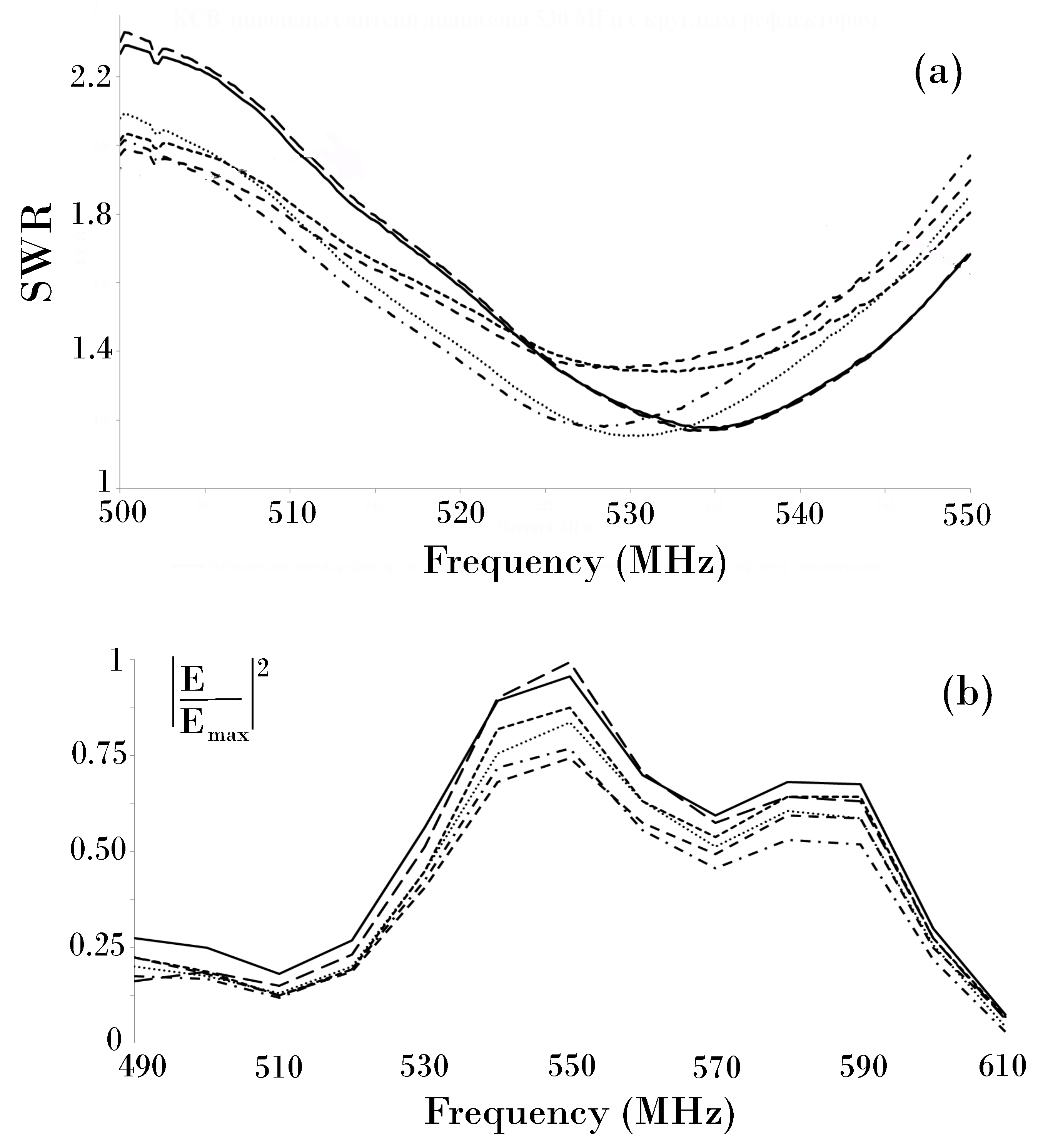
3.2. Standard Dipole Antennas at 540 MHz
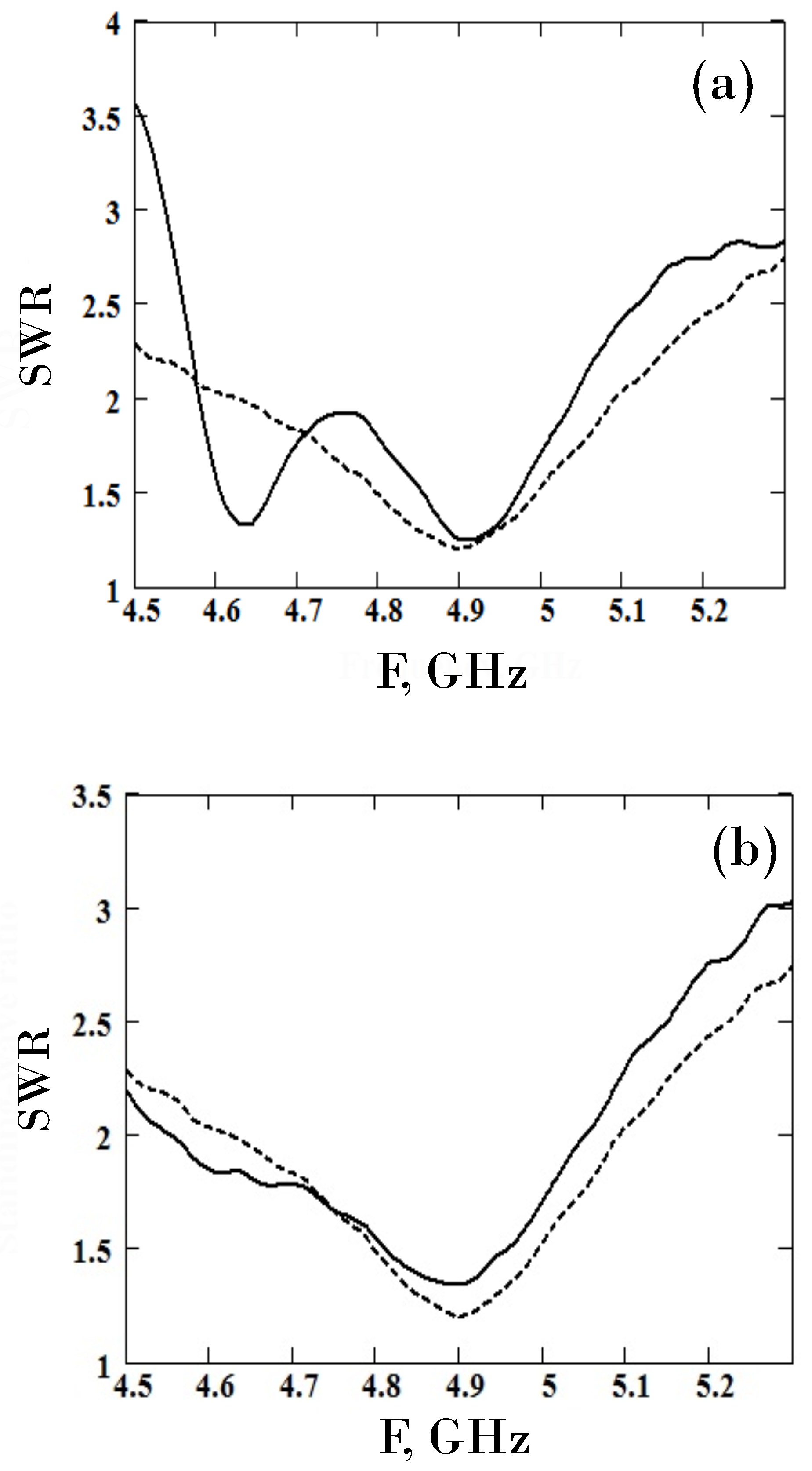
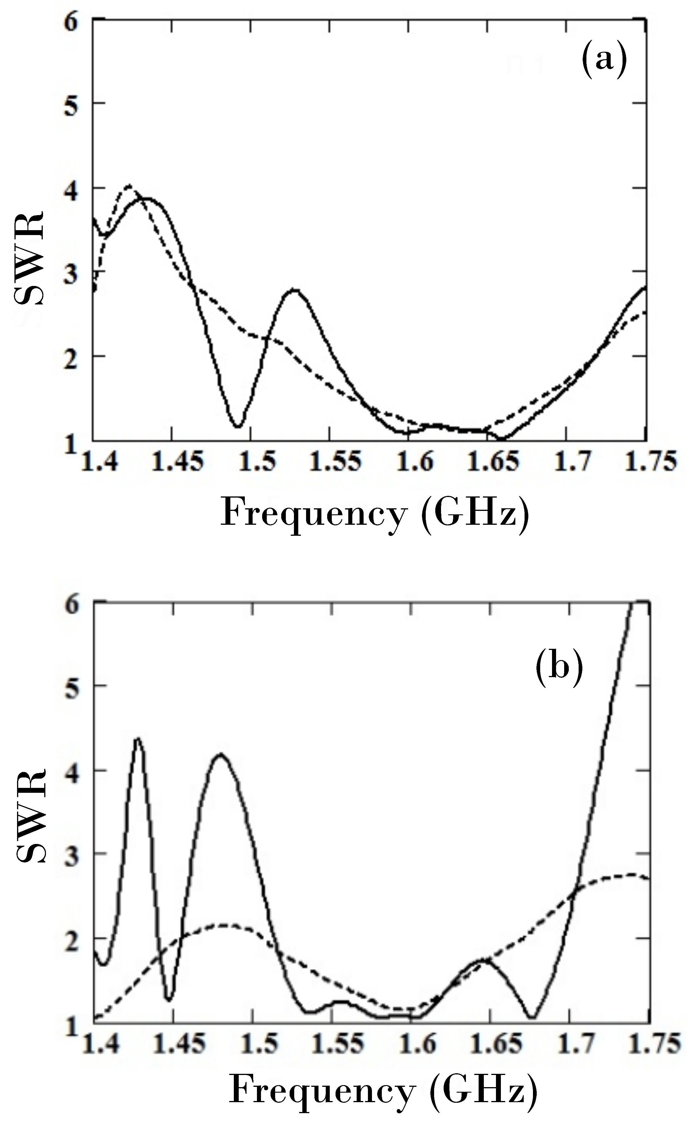
Several prototypes of a dipole antenna operating at 540 MHz and completely made from GCM were created. Their metal analogs were dipole mirror parabolic antennas operating at 540 MHz and 1040 MHz, with one central rod for attaching to the main mirror, as antennas generally used for radio astronomical measurements [41].
The whiskers of the standard dipole composite antennas were made from either carbon fiber or carbon fabric, using the same technology as for specialized dipole antennas. The reflectors, of circular shape, consisted of Zoltek Panex carbon fabric. The length of the whiskers is 28 cm, and the radius of the reflector is 30 cm. The weight of the composite material reflector is 1.5–2 times less than that of its metal analog. The main radiation properties of the prototypes were measured and compared with those of their metal analogs. The influence of the types of reflector and fiber laying on the antenna parameters were estimated. Figure 5 shows the SWRs and the emitted power frequency dependence of six different protopypes with the following characteristics: (i) metal radiating elements and metal reflector, (ii) metal radiating elements and carbon fabric reflector, (iii) curricular winding of the carbon fiber on the dielectric insert and metal reflector, (iv) longitudinal laying of the carbon fiber and metal reflector, (v) curricular winding of the fiber and carbon fabric reflector, and (vi) longitudinal laying of the fiber and carbon fabric reflector.
A good agreement between the measured characteristics of the five composite antenna prototypes and of their metal analog was observed, as shown in Figure 5, which is quite satisfactory for the laboratory tests.

4. Horn Antennas

GCM microwave horn antennas were realized for operating frequencies belonging to two ranges: (i) the L–range with a central frequency of 1.6 GHz, and (ii) the C-range with a central frequency of 5 GHz. The antenna prototypes consist of a horn connected to a segment of circular waveguide. Their characteristic parameters were determined owing to a theoretical modeling considering a waveguide with circular cross section and finite wall thickness, immersed in vacuum. The conductivity of the waveguide’s walls was described by a uniaxial permittivity tensor with nonzero diagonal elements. A dispersion equation was obtained taking into account the boundary conditions for the tangential components of the fields at the boundaries of the walls [38]. This equation allowed us to estimate the geometrical parameters of the waveguide segment of the horn antenna enabling an efficient radiation of the transverse fundamental mode H 11 of the circular waveguide (or of the mode H 01 of a rectangular waveguide) [42]. For our prototypes, the scale of the skin layer was much less than the thickness of the antenna walls.

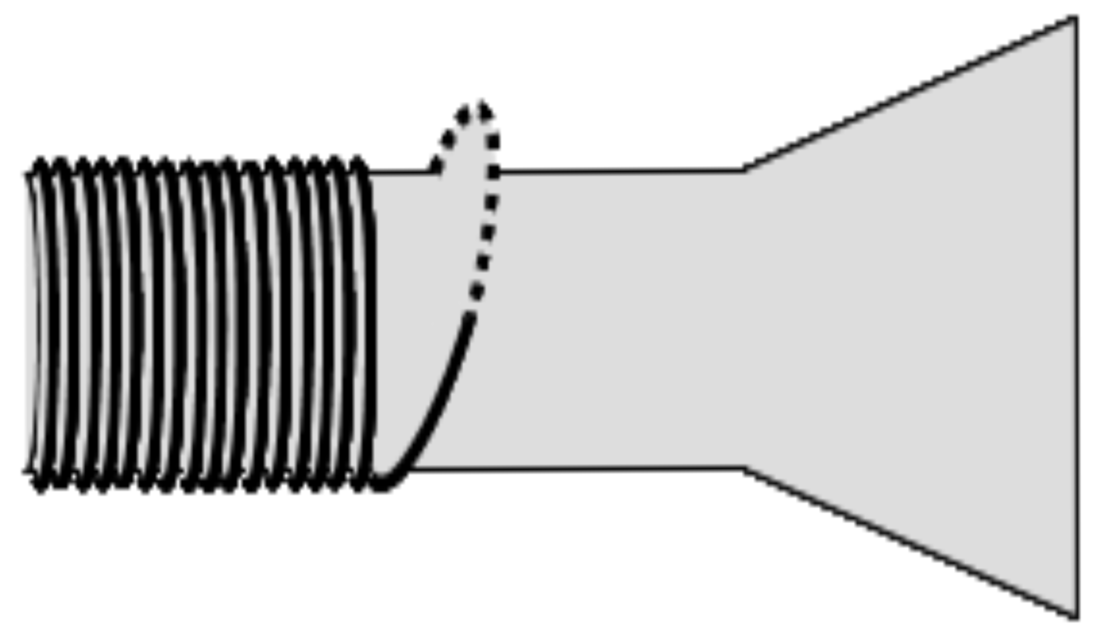
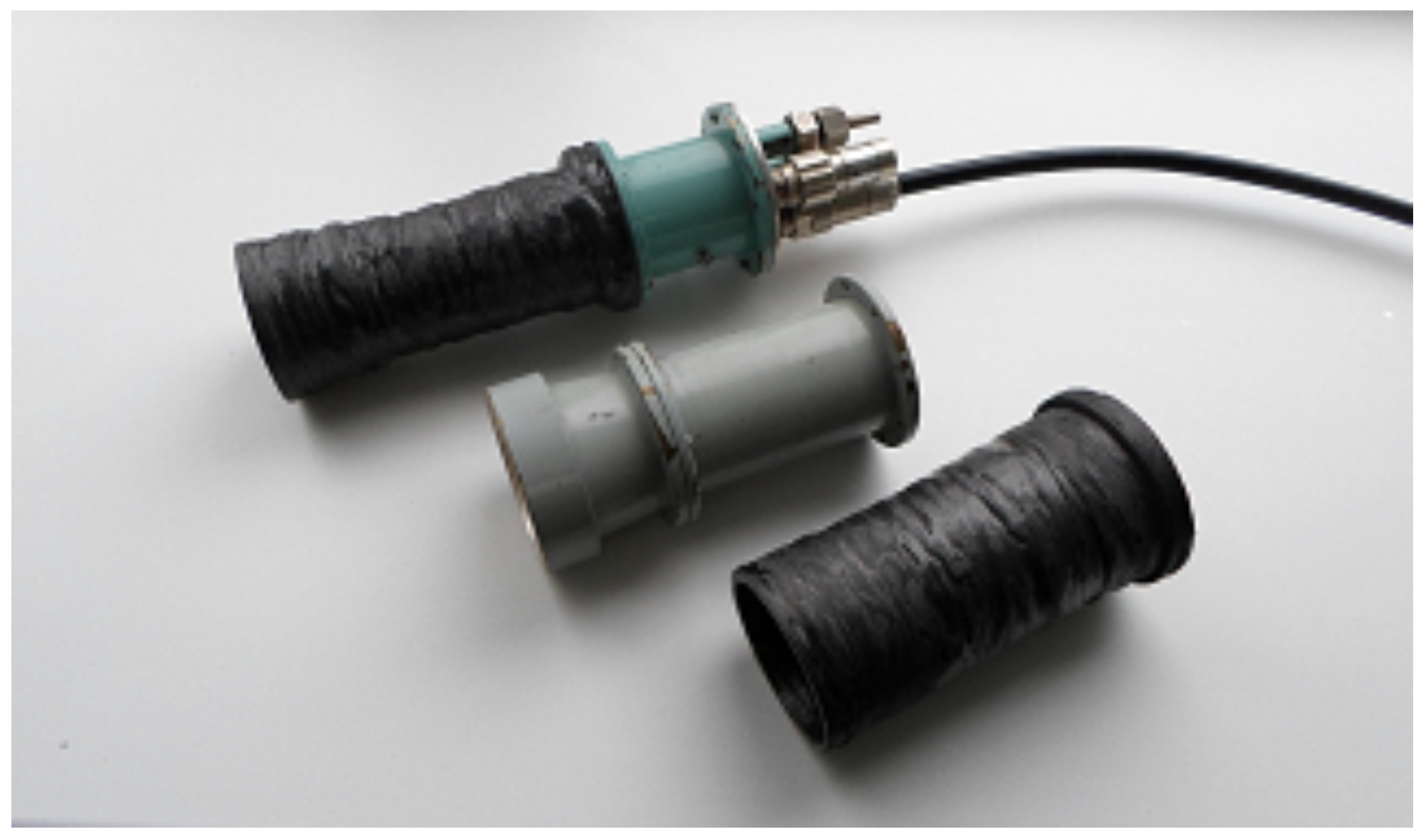
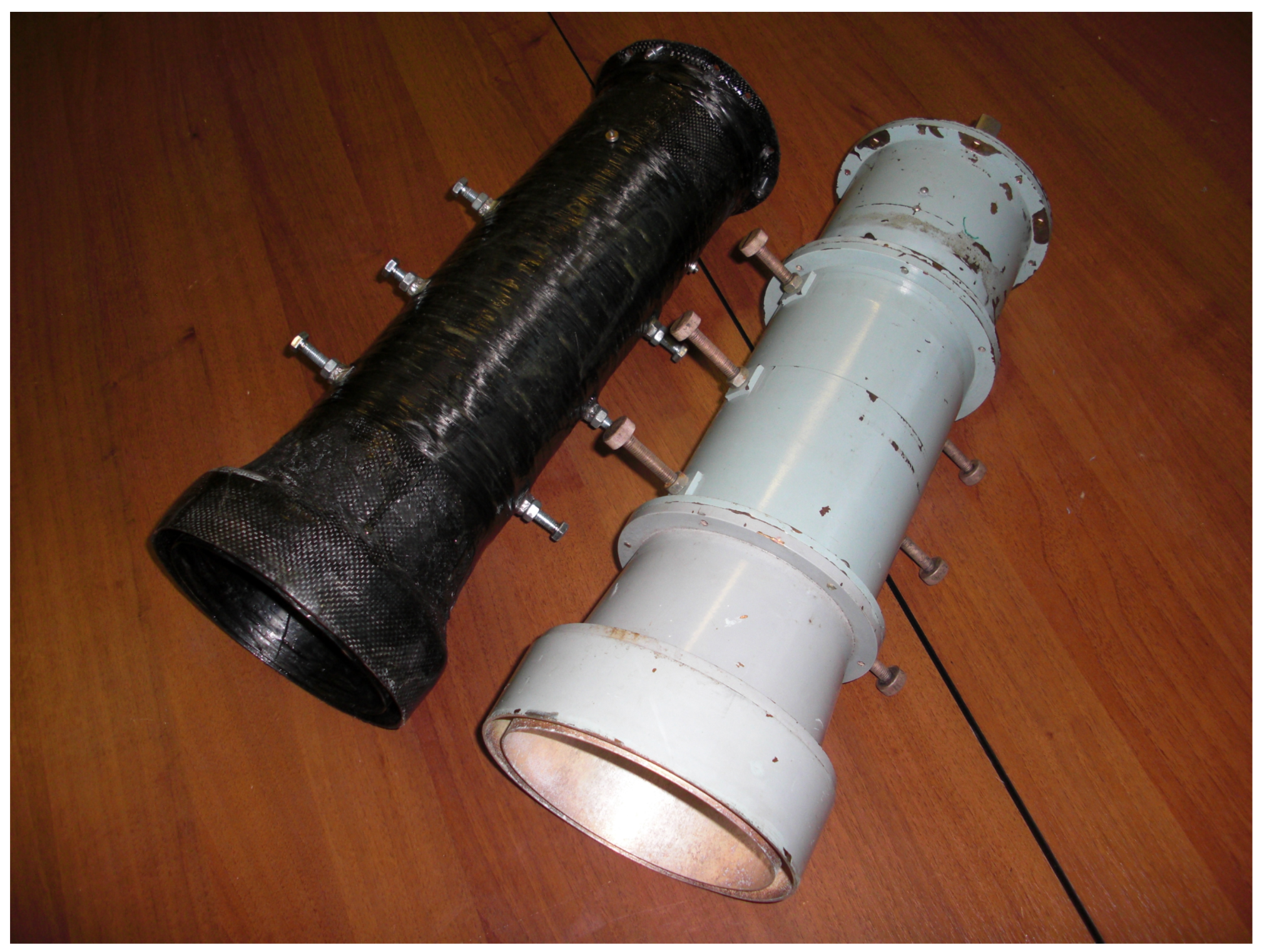
4.1. Manufacturing Horn Antennas

During the manufacturing of the GCM horn antennas, we used either Zoltek Panex carbon fiber or fabric, as well as resin modified by graphene powder. Please note that the conductivity of the composite used was quasi-isotropic. To create the antenna, a blank matrix of duralumin was made, with an external size coinciding with the calculated geometric parameters of the device. Then the required number of layers of graphene-containing carbon fiber (or fabric) were applied to the external part of the blank using transverse winding (Figure 6). To ensure the required robustness of the construction, the thickness of the waveguide walls was chosen of the order of 3–5 mm. The blank matrix was separated from the specimen after the solidification of the antenna walls. The removal of the surface roughness of internal walls was reached owing to vacuum shaping. The manufacturing procedures of the L-range and the C-range antennas were the same [23,25]. Two orthogonal dipoles were used as excitation devices for all the carbon-based antennas and their metal analogs. Figure 7 shows the C-range antennas made from metal, fabric, and fiber. They consist of a horn connected to the segment of a circular waveguide of diameter 4.2 cm (with opening diameter of 5 cm); the length of the aperture is 4.5 cm. The weight of the metal C-range antenna (composite antenna) is 510 g (140 g).
The polarization characteristics of the composite antennas were studied under laboratory conditions using the rotation of a linearly polarized emitting antenna around its longitudinal axis. The composite antennas were used as receivers and equipped with a polarization unit based on a circular waveguide. Figure 8 shows L-range horn antennas with polarization units made of composite fiber and metal. The diameter of the circular waveguide and of the opening are is 12.5 cm and 15.2 cm, respectively; the length of the horn is 14.5 cm. The weight of the composite L-range antenna is 0.5 kg, whereas that of the metal one amounts about 8 kg.
The radiation patterns, the SWRs, the emitted power frequency dependences and the polarization properties of the composite antennas were analyzed. Please note that these results can be used to estimate the antennas’ gains.

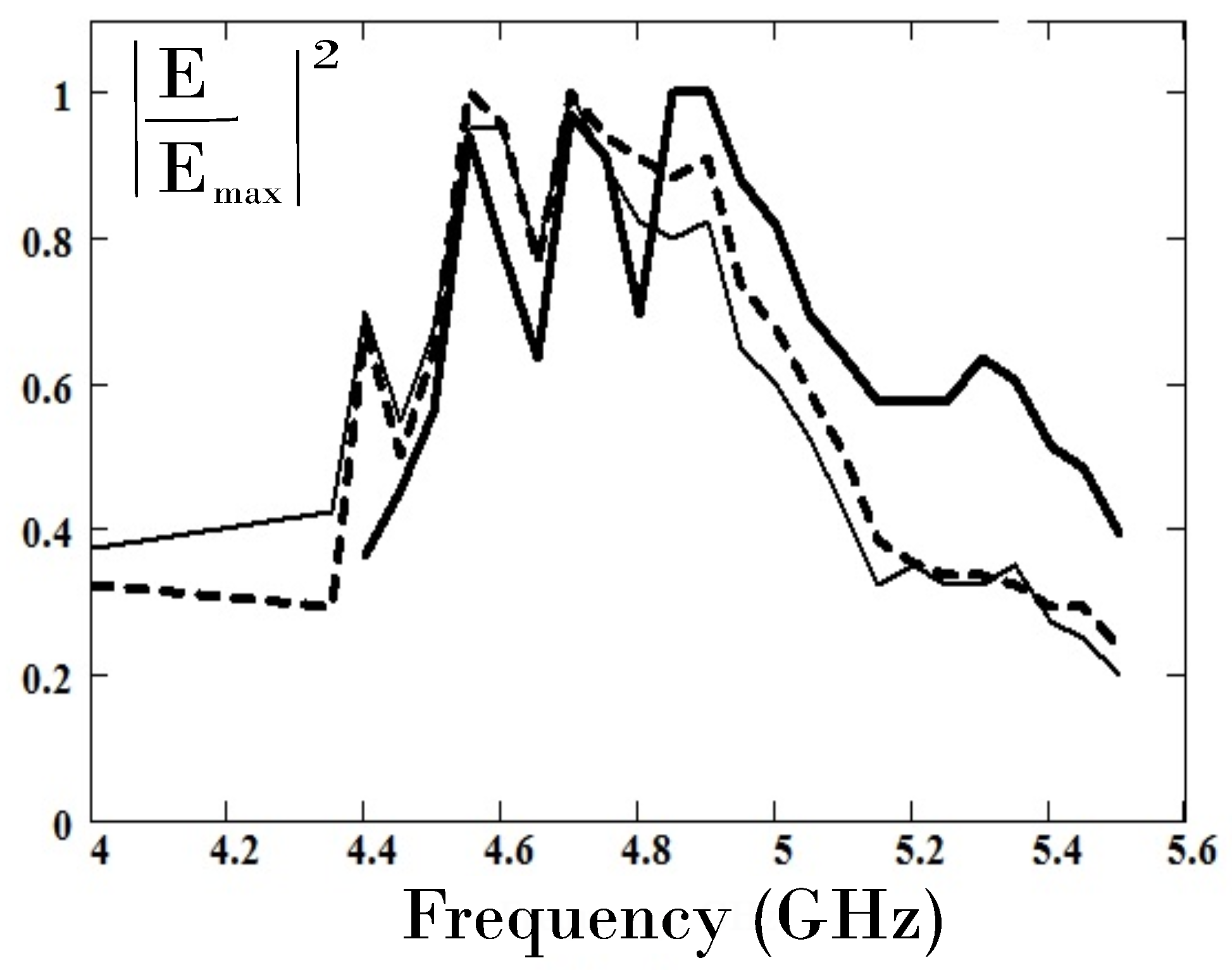
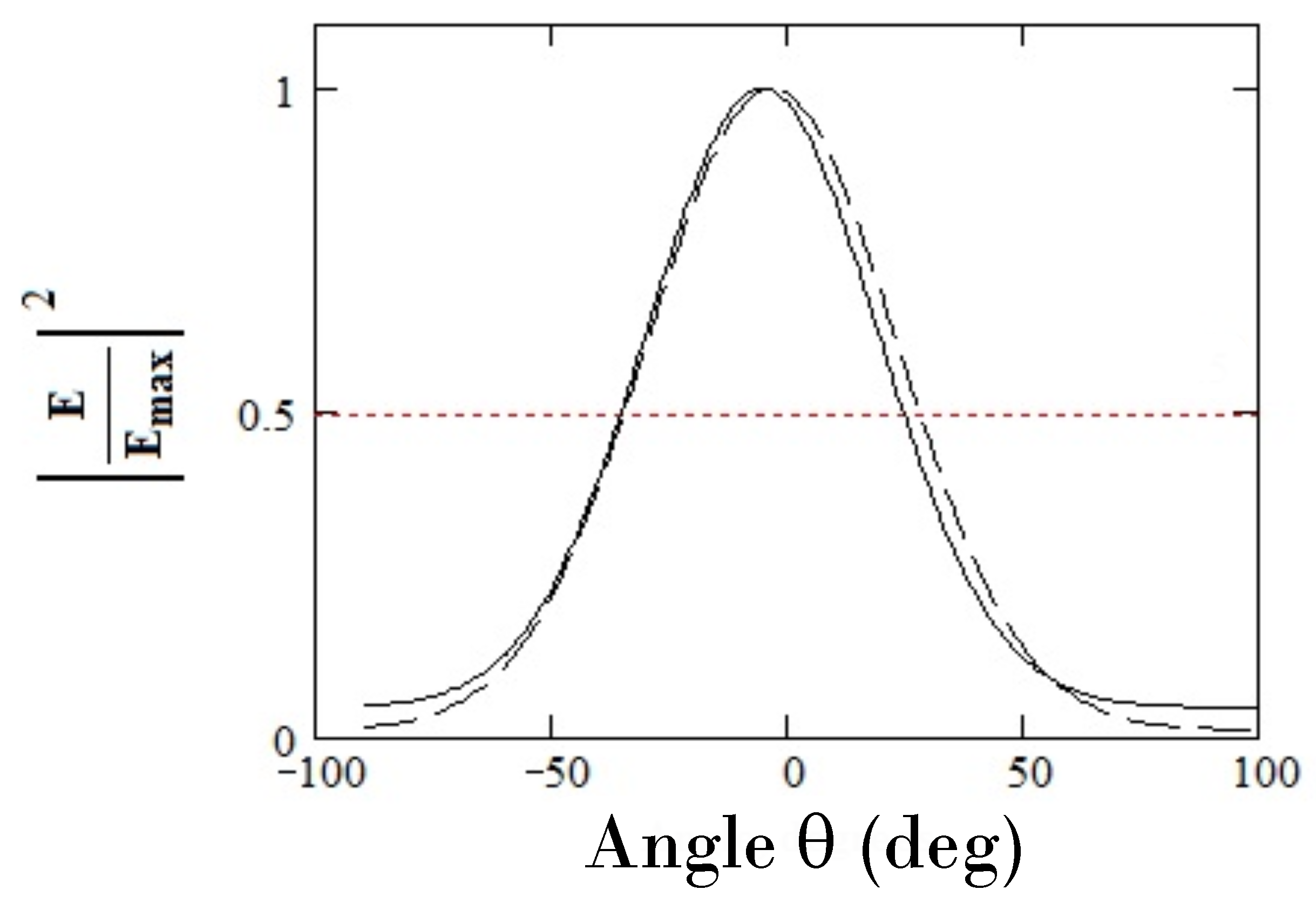
4.2. Radiation Properties of the Horn Antennas

The measurements of the radiation properties of the horn antennas were performed under laboratory conditions without using an anechoic chamber. Receiving and emitting antennas were located far from each other. The characteristics of the GCM antenna, as the SWR, the emitted power frequency dependence and the radiation pattern, were compared with those of a metal antenna with the same geometry and size. Figure 9 and Figure 10 present respectively the SWRs and the emitted power frequency dependence of C-range antennas made from fiber- and fabric-composites as well as of their metal analog. One can observe that the SWR’s curves are smoother for the composite antennas compared to their metal analog, and that their minimum values are roughly the same. The behavior of the SWRs and the emitted power frequency dependence does not depend on the carbon materials.
Please note that the main lobes of the radiation patterns of composite antennas and their metal analogs, measured in the frequency range 4.7–5 GHz, coincide very well within the limits of measurement uncertainties for both vertical and horizontal polarizations of the emitted signals [25].
Similar results were obtained for the L-range antennas. The SWRs of L-range antennas made from carbon-fiber and metal were measured without and with their polarization units, as can be observed in Figure 11 which shows that the presence of a polarization unit only slightly changes the width of the antennas’ working frequency intervals where the SWR value is less than 1.4 .
Figure 12 represents the main lobes of the radiation patterns of the metal and the composite L-range antennas. The measured values do not depend on the presence of a polarization unit. The difference about 7 % between the half-widths of the radiation patterns of both antennas is not greater, under laboratory conditions, than the measurement uncertainties, which are due to the reflections of the signals on the surrounding equipment.

4.3. Polarization Characteristics of Horn Antennas

The measurements of the polarization characteristics of the carbon fiber horn antenna and its metal analog were performed under laboratory conditions, using a polarization device built on the basis of a circular waveguide (see Figure 13). The antennas were used as receivers, whereas the emitter was a standard antenna that could be rotated around its axis.
As shown by the left panel of Figure 13, the horn antenna consists of two receiving dipoles (1), matching plexiglas plates (2), and six polarization rods (3). The plexiglas plates are used for a preliminary tuning of the antenna. The six rods inside the waveguide provide the phase shifts necessary for the generation of elliptically polarized waves. The cross section of the horn antenna exhibits the two orthogonal dipoles d 1 and d 2 (Figure 13, right-hand side panel). The angle between their axes and the rods is equal to 45 ° ; ϕ is the angle between their axes and the straight line OO’ which is the projection on the cross section of the plane of polarization of the input signal’s electric field. Please note that the rotation of the emitting antenna provides rotated linearly polarized signals at the opening of the receiving horn antenna. The polarization characteristics of the composite and the metal antennas were measured by the two orthogonal dipoles. As is seen in Figure 11, the working frequency interval is equal to 1.55 1.7 GHz (without a polarization unit) and 1.55 1.65 GHz (in the presence of a polarization unit), for the composite antenna and its metal analog.
Figure 14 shows the square E / E max 2 of the normalized electric field amplitude of the composite antenna, for two orthogonal (to each other) polarizations of the signal corresponding to two orthogonal receiving dipoles (curves 1 and 2), at frequencies of 1.55 GHz and 1.575 GHz, as a function of the angle ϕ , respectively. Figure 15 shows a similar dependence for the metal antenna at 1.55 GHz.
One can see in Figure 14 and Figure 15 that the ellipticity coefficient E min / E max 2 is close to 0.3 ( 0.55 ) for the composite (metal) antenna. Five frequencies lying in the range 1.55–1.65 GHz were chosen for measuring the polarization characteristics. It should be noted that the ellipticity of the composite antenna weakly depends on the signal’s frequency. For the metal antenna, the ellipticity varies within the interval 0.55 0.8 and reaches a maximum near 1.6 GHz. Variations of the antenna ellipticity can be due to the different damping factors of the left- and right-hand circularly polarized waves. The difference between composite and metal horn antennas is determined by their polarization coefficients, which are 1.5–2 times smaller for composite antennas than for metal ones. They may be explained by ohmic losses and wall conductivity anisotropy. Please note that the results obtained for the composite antenna made from carbon fabric have shown that the composite horn antenna and its metal analogue possess almost the same polarization characteristics.

5. Conclusions

It is shown that microwave dipole and horn antennas made from carbone composite materials modified by graphene structures are capable of operating efficiently and that their main radiation properties are identical to those of their metal analogs. Composite antennas’ prototypes designed under laboratory conditions exhibit temperature stability, durability, and reduced weight compared to metal antennas. For example, the weights of the L-range metal and composite antennas are 8 kg and 0.5 kg, respectively. Moreover, the composite dipole and horn antennas have almost the same amplitude frequency response functions and radiation patterns as their metal analogs. Composite and metal horn antennas are different only as to their polarization characteristics. It should be noted that the anisotropy of the conductivity of GCMs can be used to obtain the desired characteristics of composite radio-technical devices. In the future, with the improvement of antenna technology, the GCM antenna devices should have substantial advantages over the metal analogs and should be able to replace them.
Over the last decade, one of the main goals of the antenna industry was to create microwave antennas with desirable radiation patterns whereas reducing their weight and cost. This can be achieved by designing new types of antennas made from GCMs.

6. Patents

Dugin, N.A.; Zaboronkova, T.M.; Chugurin, V.V.; Myasnikov, E.N. Antenna-feeder the microwave device from graphene-containing carbon composite material and its manufactoring, Russian Federation Patent N–RU2016/2577918 (C1), 2016-02-18.

Author Contributions

Conceptualization, N.A.D. and T.M.Z.; methodology, N.A.D. and T.M.Z.; software, G.R.B.; validation, N.A.D.; formal analysis, T.M.Z.; investigation, N.A.D., T.M.Z. and G.R.B.; resources, N.A.D. and T.M.Z.; data curation, N.A.D.; writing–original draft preparation, N.A.D. and T.M.Z.; writing–review and editing, T.M.Z. and C.K.; visualization, G.R.B. and C.K.; supervision, N.A.D.; project administration, N.A.D. and T.M.Z.; funding acquisition, N.A.D. All authors have read and agreed to the published version of the manuscript.

Funding

This research was funded by the Russian Science Foundation (grant number 14-12-00510) and by the Ministry of Education and Science of the Russian Federation (project N-3.2722.2017/4.6).

Conflicts of Interest

The authors declare no conflict of interest.

Abbreviations

The following abbreviations are used in this manuscript:
SWRStanding wave ratio
GCMGraphene-containing carbon composite material

References

  1. Novoselov, K.S.; Jiang, D.; Schedin, F.; Booth, T.J.; Khotkevich, V.V.; Morozov, S.V.; Giem, A.K. Two-dimensional atomic crystals. Proc. Nat. Acad. Sci. USA 2005, 102, 10451–10453. [Google Scholar] [CrossRef] [PubMed] [Green Version]
  2. Novoselov, K.S.; Geim, A.K.; Morozov, S.V.; Jiang, D.; Zhang, Y.; Dubbonos, S.V.; Grigorieva, I.V.; Firsov, A.A. Electric field effect in atomically thin carbon films. Science 2004, 306, 666–669. [Google Scholar] [CrossRef] [PubMed] [Green Version]
  3. Berger, C.; Song, Z.; Li, T.; Li, X.; Ogbazghi, A.Y.; Feng, R.; Dai, Z.; Marchenkov, A.N.; Conrad, E.H.; First, P.N.; et al. Ultrathin epitaxial graphite: 2D electron gas properties and a route toward graphene-based nanoelectronics. J. Phys. Chem. B 2004, 108, 19912–19915. [Google Scholar] [CrossRef] [Green Version]
  4. Hernandez, Y.; Nicolosi, V.; Lotya, M.; Blighe, F.M.; Sun, Z.; De, S.; McGovern, I.T.; Holland, B.; Byrne, M.; Gun’Ko, Y.K.; et al. High-yield production of graphene by liquid-phase exfoliation of graphite. Nature Nanotech. 2008, 3, 563–568. [Google Scholar] [CrossRef] [Green Version]
  5. Engheta, N.; Ziolkowski, R.W. (Eds.) Metamaterials: Physics and Engineering Explorations; Wiley-IEEE: Hoboken, NJ, USA, 2006. [Google Scholar]
  6. Slyusar, V.I. Metamaterials in antenna technology: History and basic principles. Electronika NTV 2009, 7, 70–79. (In Russian) [Google Scholar]
  7. Lier, E. Review of soft and hard horn antennas, including metamaterial-based hybrid-mode horns. IEEE Antennas. Propag. Mag. 2010, 52, 31–39. [Google Scholar] [CrossRef]
  8. Tang, M.C.; Xiao, S.; Wang, B.; Guan, J.; Deng, T. Improved performance of a microstrip phased array using broadband and ultra-low-loss metamaterial slabs. IEEE Antennas. Propag. Mag. 2011, 53, 31–41. [Google Scholar] [CrossRef]
  9. Vendik, I.B.; Vendik, O.G. Metamaterials and their application in microwaves: A Review. Tech. Phys. 2013, 58, 1–24. [Google Scholar] [CrossRef]
  10. Veselago, V.G. The electrodynamics of substances with simultaneous negative values of ε and μ. Sov. Phys. Uspekhi 1967, 10, 509–514. [Google Scholar] [CrossRef]
  11. Temelkuara, B.; Bayindir, M.; Ozbay, E.; Biswas, R.; Sigalas, M.M.; Tuttle, G.; Ho, K.M. Photonic crystal-based resonant antenna with a very high directivity. J. Appl. Phys. 2000, 87, 603–605. [Google Scholar] [CrossRef] [Green Version]
  12. Ge, Z.C.; Zhang, W.X.; Liu, Z.G.; Gu, Y.Y. Broadband and high-gain printed antennas constructed from Fabry-Perot resonator structure using EBG or FSS cover. Microw. Opt. Technol. Lett. 2006, 48, 1272–1274. [Google Scholar] [CrossRef]
  13. Marques, R.; Martin, F.; Sorolla, M. Metamaterials with Negative Parameters: Theory, Design and Microwave Applications; Wiley Series in Microwave and Optical Engineering; Wiley-Blackwell: Hoboken, NJ, USA, 2008. [Google Scholar]
  14. Bychkov, I.V.; Zotov, I.S.; Fedii, A.A. Studing microwave transmission and reflection in multilayer CaSO4·2H2O—Graphite composites. Tech. Phys. Lett. 2011, 37, 689–691. [Google Scholar] [CrossRef]
  15. Weily, A.R.; Horvath, L.; Esselle, K.P.; Sanders, B.C.; Bird, T.S. A planar resonator antenna based on a woodpile EBG material. IEEE Trans. Antennas Propag. 2005, 53, 216–223. [Google Scholar] [CrossRef]
  16. Caiazzo, M.; Maci, S.; Engheta, N. A metamaterial surface for compact cavity resonators. IEEE Antennas Wirel. Propag. Lett. 2004, 3, 261–264. [Google Scholar] [CrossRef]
  17. Zhigang, X.; Xu, H. Low refractive metamaterials for gain enhancement of horn antenna. J. Infrared Millim. Terahertz Waves 2009, 30, 225–232. [Google Scholar]
  18. Lashab, M.; Hraga, H.I.; Read, A.A.; Zebiri, C.; Benabdelaziz, F.; Jones, S.M.R. Horn antennas loaded with metamaterial for UWB applications. PIERS Online 2011, 7, 161–165. [Google Scholar]
  19. Lai, A.; Caloz, C.; Itoh, T. Composite right/left-handed transmission line metamaterials. IEEE Microw. Mag. 2004, 5, 34–50. [Google Scholar] [CrossRef]
  20. Hu, J.; Yan, C.S.; Lin, Q.C. A new patch antenna with metamaterial cover. J. Zhejiang Univ. Sci. A 2006, 7, 89–94. [Google Scholar] [CrossRef]
  21. Rybin, V.V.; Kuznetsov, P.A.; Ulin, I.V.; Farmakovskii, B.V.; Bakhareva, V.E. Nanomaterials structural and functional class. Vopr. Mater. 2006, 1, 169–178. (In Russian) [Google Scholar]
  22. Maher, F.E.; Strong, V.; Dubin, S.; Kaner, R.B. Laser scribing of high-performance and flexible graphene-based electrochemical capacitors. Science 2012, 335, 1326–1330. [Google Scholar]
  23. Dugin, N.A.; Zaboronkova, T.M.; Chugurin, V.V.; Myasnikov, E.N. Antenna-Feeder the Microwave Device From Graphene-Containing Carbon Composite Material and Its Manufactoring. RF Patent N–RU2016/2577918 (C1), 18 February 2016. [Google Scholar]
  24. Dugin, N.A.; Zaboronkova, T.M.; Myasnikov, E.N.; Belyaev, G.R.; Lobastov, V.V. Electrodynamic characteristics of dipole antennas made of graphene-containing carbon composite materials. J. Commun. Technol. Electron. 2018, 63, 864–867. [Google Scholar] [CrossRef]
  25. Dugin, N.A.; Zaboronkova, T.M.; Myasnikov, E.N. Using carbon-based composite materials for manufactoring C-range antenna devices. Latv. J. Phys. Tech. Sci. 2016, 53, 17–24. [Google Scholar]
  26. Dugin, N.A.; Zaboronkova, T.M.; Myasnikov, E.N. Antenna-waveguide microwave devices of carbon composition materials. Tech. Phys. Lett. 2016, 42, 598–600. [Google Scholar] [CrossRef]
  27. Ovechkin, G.I.; Golovanova, V.V.; Dvirnyi, G.V. Transformable Antenna of the Umbrella-Type Spacecraft. RF Patent N-RU2011/2427949 (C1), 20 April 2011. [Google Scholar]
  28. Chung-Yen Yang Method of Forming Antenna by Utilizing Graphene. U.S. Patent N-US2013/0004658 (A1), 3 January 2013.
  29. Gi, C.C.; Soon, O.S. Metamaterial And Manufacturing Method at the Same. U.S. Patent N-US2012/013989 (A1), 25 January 2012. [Google Scholar]
  30. Bychkov, I.V.; Zotov, I.S.; Fedii, A.A. Reflection properties of electromagnetic crystal based composite material. In Proceedings of the 3rd International Congress on Advanced Electromagnetic Materials in Microwaves and Optics, London, UK, 31 August–4 September 2009; p. 602. [Google Scholar]
  31. Kazantseva, N.E.; Ryvkina, N.G.; Chmutin, I.A. Promising materials for microwave absorbers. J. Commun. Technol. Electron. 2003, 48, 173–184. [Google Scholar]
  32. Giboney, K.S. Gap-Mode Waveguide. U.S. Patent N-US2012/0243823 (A1), 27 September 2012. [Google Scholar]
  33. Dugin, N.A.; Zaboronkova, T.M.; Chugurin, V.V.; Myasnikov, E.N. Study of electromagnetic properties of multylayer graphene fractal structures by remote method. In Proceedings of the 21th annual International Conference on Advanced Laser Technologies, Budva, Montenegro, 16–20 Spetember 2013; p. 192. [Google Scholar]
  34. Kudrin, A.V.; Zaitseva, A.S.; Zaboronkova, T.M.; Krafft, C. Analysis of a strip antenna located on the interface between a uniaxial plasma and an isotropic medium. In Proceedings of the 11th European Conference on Antennas and Propagation, Paris, France, 19–24 March 2017; pp. 3574–3578. [Google Scholar]
  35. Kudrin, A.V.; Zaitseva, A.S.; Zaboronkova, T.M.; Krafft, C. Current distribution and input impedance of a circular loop antenna located on the surface of a gyromagnetic cylinder. In Proceedings of the International Conference Days on Diffraction 2018, St-Petersburg, Russia, 4–8 June 2018; pp. 192–197. [Google Scholar]
  36. Kudrin, A.V.; Zaboronkova, T.M.; Zaitseva, A.S.; Spagnolo, B. Theory of strip antenna located at a plane interface of a uniaxial metamaterial and an isotropic magnetodielectric. IEEE Trans. Ant. Prop. 2020, 68, 195–206. [Google Scholar] [CrossRef]
  37. Zaboronkova, T.M.; Dugin, N.A.; Myasnikov, E.N. Microwave horn antenna made of a graphene-containing carbon composite material. In Proceedings of the 9th European Conference on Antennas and Propagation, Lisbon, Portugal, 13–17 April 2015; pp. 7228220-1–7228220-2. [Google Scholar]
  38. Dugin, N.A.; Belyaev, G.R.; Zaboronkova, T.M.; Lobastov, V.G. Polarization characteristics of graphene-containing composite horn antenna. In Proceedings of the International Conference Days on Diffraction 2018, St-Petersburg, Russia, 4–8 June 2018; pp. 88–92. [Google Scholar]
  39. Dugin, N.A.; Zaboronkova, T.M.; Myasnikov, E.N.; Belyaev, G.R. Electrodynamic characteristics of horn microwave antennas made of graphene-containing carbon–composite materials. Tech. Phys. 2018, 63, 268–273. [Google Scholar] [CrossRef]
  40. Available online: https://zoltek.com/products/px35/ (accessed on 20 January 2020).
  41. Tseitlin, N.M. Methods of Measurement of Antenna Characteristics; Radio i Svyaz’: Moscow, Russia, 1985. (In Russian) [Google Scholar]
  42. Felsen, L.B.; Marcuvitz, N. Radiation and Scattering of Waves; Prentice-Hall: Englewood Cliffs, NJ, USA, 1973. [Google Scholar]
Figure 1. View of the dipole antenna operating at 600 MHz with its radiation elements made from carbon fiber.
Electronics 09 00590 g001
Figure 2. Radiation elements of the dipole antenna, with longitudinal laying on the dielectric insert (top panel) and circular winding on the dielectric insert (bottom panel).
Electronics 09 00590 g002
Figure 3. Dipole antenna operating at 200 MHz. (a) SWRs and (b) Square of the normalized field amplitude of the emitted signal as a function of frequency for 3 different prototypes with (i) metal radiating elements (curve 1, solid line), (ii) a longitudinal laying of the fiber on the fluoroplastic insert (curve 2, dashed line), and (iii) curricular winding of the fiber on the duralumin insert (curve 3, dashed-dotted line). E max is the maximum value of the field amplitude.
Electronics 09 00590 g003
Figure 4. Dipole antenna operating at 600 MHz. (a) Radiation pattern and (b) Square of the normalized field amplitude of the emitted signal as a function of frequency for four different prototypes with (i) metal radiating elements (solid line), (ii) a longitudinal laying of the carbon fiber on the duralumin base (dashed line), (iii) a curricular winding of the fiber on the fluoroplastic insert (short dashed-dotted line), and (iv) a curricular winding of the fiber on the duralumin insert (long dashed-dotted line). E max is the maximum value of the field amplitude.
Electronics 09 00590 g004
Figure 5. Dipole antenna at 540 MHz. (a) SWRs and (b) Square of the normalized field amplitude of the emitted signal as a function of frequency for six different protopypes with the following charcateristics: (i) metal radiating elements and metal reflector (solid line), (ii) metal radiating elements and carbon fabric reflector (long-dashed line), (iii) curricular winding of the carbon fiber and metal reflector (dashed line), (iv) longitudinal laying of the carbon fiber and metal reflector (dashed-dotted line), (v) curricular winding of the fiber and carbon fabric reflector (dotted line), and (vi) longitudinal laying of the fiber and carbon fabric reflector (short-dashed line). E max is the maximum value of the field amplitude.
Electronics 09 00590 g005
Figure 6. Transverse winding of the carbon fiber on the blank matrix.
Electronics 09 00590 g006
Figure 7. View of C-range horn antennas made from fabric (right), metal (center) and fiber (equipped with elements for antenna feeding, left).
Electronics 09 00590 g007
Figure 8. View of L-range horn antennas with polarization units made from fiber (left) and metal (right).
Electronics 09 00590 g008
Figure 9. SWRs of C-range horn antennas made from (a) Fiber (dashed line) and metal (solid line), and (b) Fiber (dashed line) and fabric (solid line).
Electronics 09 00590 g009
Figure 10. Square of the normalized field amplitude of the emitted signal as a function of frequency of C-range antennas made from fiber (dashed line), fabric (thin solid line), and metal (thick solid line). E max is the maximum value of the field amplitude.
Electronics 09 00590 g010
Figure 11. SWRs of L-range antennas made from metal (solid line) and fiber (dashed line), (a) without and (b) with a polarization unit.
Electronics 09 00590 g011
Figure 12. Radiation patterns of L-range antennas made from metal (solid line) and fiber (dashed line). E max is the maximum value of the field amplitude.
Electronics 09 00590 g012
Figure 13. Geometry of the horn antenna with a polarization unit (left panel) and its cross-section showing the two orthogonal dipoles d 1 and d 2 used for the measure of the polarization (right panel).
Electronics 09 00590 g013
Figure 14. Square of the normalized amplitude of the signal received by the composite horn antenna as a function of the rotation angle ϕ at 1.55 GHz (solid line) and 1.575 GHz (dashed line).
Electronics 09 00590 g014
Figure 15. Square of the normalized amplitude of the signal received by the metal horn antenna as a function of the rotation angle ϕ at 1.55 GHz: measured signal (dashed line) and interpolation by a sinusoidal function of ϕ (solid line).
Electronics 09 00590 g015
Table 1. Main antenna properties and parameters in the working frequency interval, for the composite prototype (with curricular winding of the fiber) and its metal analog (see Section 3 and Section 4 for more details). DA: dipole antenna; HA: horn antenna; PU: polarization unit; E m a x ( G C M ) and E m a x ( M e t ) are the maximum values of the field amplitude of the emitted signal for the GCM prototype and its metal analog, respectively; the sign “*” denotes the weight of the reflector of the dipole antenna at 540 MHz; the reflector of dipole antennas at 200 MHz and 600 MHz are made from metal; the weight is indicated for GCM antennas manufactured in laboratory conditions (in industrial conditions it may be two times smaller).
Antenna PropertiesMaterial TypeDA 200 MHzDA 600 MHzDA 540 MHzHA 1.6 GHz
without PU
HA 1.6 GHz
with PU
HA 5 GHz
without PU
SWR min Metal GCM 1.1 1.07 1.15 1.13 1.2 1.2 1.05 1.1 1.05 1.15 1.3 1.25
  Main - lobe width ( degree ) of Radiation Pattern Metal GCM 86 90 80 75 58.6 61.4 58.6 61.4 60 60
E m a x ( G C M ) E m a x ( M e t ) 2 Metal GCM 1 1.08 1 0.93 1 1.03 1 0.9 1 0.88 1 1.1
Polarization Metal GCM thread 0.55 0.8 0.3 0.4
Weight (kg) Metal GCM 1.91 ( A l ) * 1.07 ( G C M ) * 8 0.5 8.2 0.7 0.51 0.14
Size (m) whiskers 0.75 whiskers 0.25 whiskers 0.28 opening 0.152 opening 0.152 opening 0.05
Table 2. Main properties of graphene-containing composite material antennas and corresponding metal analogs.
PARAMETERSZoltek Px 35BrassAl (Aluminium)
Electrical resistivity (Ωm)15.5 · 10−66 · 10−83 · 10−8
Tensile strength (MPa)4137450100
Tensile modulus (GPa)24210075
Density (kg·m−3)181085002700
Coefficient of thermal expansion (°K−1)8 · 10−819.1 · 10−623.8 · 10−6
Temperature of melting (decomposition) of metal (GCM) (°C)>650900650

