Article

Heat Transfer Study in Breast Tumor Phantom during Microwave Ablation: Modeling and Experimental Results for Three Different Antennas

by
Rocío Ortega-Palacios
1,
Citlalli Jessica Trujillo-Romero
2,
Mario Francisco Jesús Cepeda-Rubio
3,
Lorenzo Leija
4 and
Arturo Vera Hernández
4,*
1
Biomedical Engineering, Universidad Politécnica de Pachuca, Hidalgo 43830, Mexico
2
Division of Medical Engineering Research, National Institute of Rehabilitation, Mexico City 14389, Mexico
3
División de Estudios de Posgrado e Investigación, Tecnológico Nacional de México, Instituto Tecnológico de la Laguna, Blvd. Revolución, Esq. Calzada Instituto Tecnológico de la Laguna, Zona Centro, Torréon 27000, COAH, Mexico
4
Electrical Engineering Department, Bioelectronics Section, Centro de Investigación y de Estudios Avanzados-IPN, Mexico City 07360, Mexico
*
Author to whom correspondence should be addressed.
Electronics 2020, 9(3), 535; https://doi.org/10.3390/electronics9030535
Submission received: 4 February 2020 / Revised: 13 March 2020 / Accepted: 17 March 2020 / Published: 24 March 2020
(This article belongs to the Special Issue Numerical Methods and Measurements in Antennas and Propagation)

Abstract

:
It is worldwide known that the most common type of cancer among women is breast cancer. Traditional procedures involve surgery, chemotherapy and radiation therapy; however, these treatments are invasive and have serious side effects. For this reason, minimally invasive thermal treatments like microwave ablation are being considered. In this study, thermal behavior of three types of slot-coaxial antennas for breast cancer microwave ablation is presented. By using finite element method (FEM), all antennas were modeled to estimate the heat transfer in breast tumor tissue surrounded by healthy breast tissue. Experimentation was carried out by using the antennas inserted inside sphere-shaped-tumor phantoms with two different diameters, 1.0 and 1.5 cm. A microwave radiation system was used to apply microwave energy to each designed antenna, which were located into the phantom. A non-interfering thermometry system was used to measure the temperature increase during the experimentation. Temperature increases, recorded by the thermal sensors placed inside the tumor phantom surrounded by healthy breast phantom, were used to validate the FEM models. The results conclude that, in all the cases, after 240 s, the three types of coaxial slot antenna reached the temperature needed produce hyperthermia of the tumor volume considered in this paper.

Graphical Abstract

1. Introduction

Worldwide, the most frequent type of cancer in women is breast cancer. In 2016, 1.685 million new cases were diagnosed and 595,690 deaths were reported [1,2]. Conventional treatments for breast cancer, such as surgery (mastectomy, lumpectomy), chemotherapy and radiation therapy, are invasive; moreover, they generated side-effects. For this reason, less invasive treatments like microwave thermal ablation (MWA) have been researched [3,4,5]. Thermal therapies have several benefits compared with conventional treatments. Those therapies may be applied with local anesthesia and done in an ambulatory hospital; minimally invasive techniques involve incisions of nearly 3 mm, which may accelerate the recovery time [6,7], so these techniques are less aggressive to the contour of the breast. Hyperthermia is a thermal cancer treatment used to potentiate the effects of conventional therapies, such as radiotherapy and chemotherapy. The most important condition for the use of this therapy is that temperature is locally increased in malignant tissue and that temperature is maintained above 41 °C, while surrounding healthy tissues remain at lower temperatures. For the hyperthermia concept, it is necessary to distinguish between hyperthermia (when temperature is between 41 and 45 °C) [8,9] and thermal ablation (when temperature exceeds 60 °C [10]). When the tissue temperature is above 41°C, normal cellular processes become deactivated in a dose-dependent manner, which eventually may result in the death of cells. In thermal ablation, tissues show areas of extensive necrosis [11].
Microwave ablation (MWA) is a promising alternative for breast cancer treatment. MWA is a local treatment for first-stage tumors and may also increase the effect of some cancer drugs [12,13]. Microwave energy radiated by a coaxial antenna induces heat in tumor tissue with minimal damage to surrounding tissue, due to differences in electric properties between healthy and tumor breast tissue.
MWA’s benefits are higher constant tumor temperatures, faster ablation times and the opportunity to apply multiple probes at the same time. MWA does not require grounding pads on the patient, which can result in skin burns. MWA creates more consistent and larger ablation zones than other ablative therapies [14,15,16]. Microwave ablation treatment of breast cancer is an encouraging treatment because of the difference in the tissue properties. Breast tumors are mostly surrounded by fat and the differences between electrical and thermal properties in fat and tumor tissues are significant; the latter may cause localized heat in the tumor.
A key element in MWA treatment is the antenna that turns electrical power into heat power. Researchers have been developing innovative antennas to treat tumors efficiently, based on minimally invasive micro-coaxial antennas [17,18,19], which can deliver a precise amount of microwave power. According to their physical characteristics, microwave antennas can be categorized as monopole, dipole, slot or choke [20].
Some proposed antennas have been successful for the treatment of malignant tumors. For example, a double-slot antenna with a high specific absorption rate (SAR) focalization was designed for Saito et al. [21]; this antenna was used in a preliminary clinical trial on a female patient with a gingival carcinoma on her right shoulder. Another common antenna, the cap-choke [22,23], has demonstrated to be an efficient applicator for tumor MWA. This design produced a high SAR near its distal tip [24,25]. Jiao et al. [26] presented a homogeneous temperature distribution in tumors using a coaxial-slot antenna. During clinical MWA treatment, it is necessary to control tissue temperature and ablation dimensions in tumors and surrounding tissue; therefore, modeling this treatment helps to plan ablation treatment.
Micro-coaxial slot antennas were chosen for this study because their construction is easy and they are very suitable for microwave ablation treatment because of their low cost and dimensions (2.5 mm of diameter). The outer and central conductors of the antennas are connected at the distal tip of the antenna. The slot from which the radiation comes out is a 1-mm ring around the outer conductor.
Microwave ablation treatment for breast cancer has been investigated in recent years at the Electromagnetic and Ultrasound Radiation Laboratory (LAREMUS) of the CINVESTAV in the Bioelectronic section of the Department of Electrical Engineering. In 2010, the computational model of a one-slot coaxial applicator for its application in the treatment of cancer was designed, constructed and validated; the validation of the computational model was performed by using ex vivo pig tissue and tissue emulators [27]. Later, in 2012, the design was modified from using a single-slot to a two-slot applicator. The applicators were fabricated and then the computational model of the antenna behavior was performed; experimentations in breast phantom were carried out, verifying that there were better results when using the new design regarding the coupling and the temperatures reached in the tested tissues [28]. This applicator was optimized in 2015 by using an algorithm which allowed finding the ideal geometry to improve the coupling with the medium. The first tests were carried out by using breast cancer cells which underwent different MWA protocols in vitro, to determine their effectiveness by eliminating such cells; encouraging results were obtained and the first approach to delineate MWA therapy as a possible treatment against breast cancer was established [29]. In 2016, an applicator was designed, with one slot but with dimensions of 1.5 mm in diameter, a smaller diameter than the previous designs. This applicator was tested in murine models, obtaining very promising results [30]. At the same time, slot antennas with different diameters have been proposed to carry out simulations with the surrounding tissues (multilayer models): adipose tissue, connective, glandular and tumor tissue [31]. In 2018, the double “short distance” was validated and the feasibility of using this method in clinical treatment was studied by testing in swine breast in vivo experimentation [32].
In this study, three types of antenna were analyzed: one single coaxial slot antenna and two types of double coaxial slot antennas. The difference between the double coaxial slot antennas is the slot spacing length; the double slot coaxial antenna has a 0.25 λeff (4.05 mm) slot distance. The other antenna, from now on referred to as a double “short distance” slot antenna, has a slot spacing length of 0.4 mm (0.025 λeff). The finite element method (FEM) was used to calculate the heat transfer inside the tumor tissue surrounded by healthy breast tissue for each type of antenna. To validate the theoretical results, experimentation was carried out by irradiating a sphere-shaped tumor phantom surrounded by breast phantom with the antennas. Microwave ablation treatment is pretended to be used at breast cancer first stages (stage 1: tumors less than 2 cm), consequently, tumor phantoms of 1.0 and 1.5 cm in diameter were tested. The microwave radiation system was used to apply microwave energy into the phantom, and a non-electromagnetic interfering thermometry system was used to measure the increase in temperature during the experimentation. The coaxial slot antenna was inserted into the phantom and 10 W microwave emission was applied during 240 s. The phantom temperature was measured with fiber-optic thermal probes every second.
The aim of this manuscript is to make a comparison of three different microcoaxial antenna geometries, which has not been done before, in order to evaluate the antenna thermal behavior, in terms of shape and distribution of temperature, when applied in breast tumor phantoms of different dimensions. In this paper we use computational methods, FEM, and we carried out tests in tissue simulators (phantoms). The results in this paper could help physicians to more accurately determine which antenna could be used in clinical treatment according to the tumor’s dimension and characteristics. It is important to mention that there are no studies in the literature that report this comparison between different kinds of antennas.

2. Materials and Methods

2.1. Antenna Design

In the last 10 years, our research group has been working on the development of micro-coaxial antennas to treat breast cancer [28,29,30,31,32,33]. Recently, a new double “short distance” antenna was developed and tested [32]. However, in order to make a complete evaluation and analysis of the performance of the two most-used antennas and the new double “short distance” antenna, a new study was carried out. Therefore, single, double and double “short distance” slot antennas were modeled and constructed to be evaluated. They were built using a semi-rigid coaxial cable (UT-085). To avoid the antenna adhesion to the ablated tissue, the antennas were placed inside a PTFE catheter [33]. One millimeter slots allow microwave propagation into the tissue. The slot distance was calculated based on the effective wavelength in breast cancer tissue at 2.45 GHz, by using Equation (1)
λ e f f = c f ϵ r
where c is the free space speed of light (m/s), f is the operating frequency (2.45 GHz), and εr = 57 is the relative permittivity of the breast cancer tissue at 2.45 GHz.
The diameters of the antennas, based on a semi-rigid, micro-coaxial commercial cable, were: 0.51 mm for the central conductor, 1.6 mm for the dielectric, 2.20 mm for the outer conductor, and 2.58 mm for the catheter; the antennas have a length of 11 cm and a 1 mm length slot. All the antennas were previously modeled and optimized [28,29,30,31,32,33]. In the case of the single slot antenna, the slot is located at 3.69 mm from the distal section, as described in Figure 1a. The SWR of this antenna, when healthy and breast tumor tissues were irradiated, was 2.9 according to the design [34]. For the double slot antenna, the slots are placed at 6 and 11 mm from the distal section. According to Equation (1), the slot spacing length corresponds to 0.25 λeff = 4.05 mm. Figure 1b depicts the double coaxial antenna design. In the case of the applicator inserted in the tumor tissue surrounded by breast tissue, it had an SWR of 1.85, calculated at 2.45 GHz, while the simulated SWR was 2.94 for the antenna surrounded by tumor tissue [35]. Finally, the design of the double short-distance slot antenna was optimized by a parametric study. In this case, the location of the slots was modified. To optimize the antenna performance, the first slot was located 2 mm from the distal tip of the antenna, while the second one was located 7 mm from the antenna tip. To obtain the best antenna design, several models, where the slot’s location was modified from the initial values up to 14 mm from the antenna tip, were evaluated. The study was implemented with increments of 1 mm. In order to choose the best antenna design, the standing wave ratio (SWR) was calculated [32]. This modeling evaluation shows that the slots of the double “short distance” slots antenna must be located at 5.5 and 6.9 mm from the distal section. According to Equation (1), the slot spacing length corresponds to 0.025 λeff = 0.40 mm. By using this antenna, an SWR of 1.07 was obtained; Figure 1c illustrates the double coaxial antenna design. The three designed antennas showed an SWR that is adequate to treat breast tumors.

2.2. Computational Model

Although several numerical techniques have been widely used in order to model different biological phenomena, the finite element method (FEM) is one of the most commonly used. The main advantage of developing models with the FEM instead of some other methods, such as the finite difference time domain method (FDTD), is that more complex geometry systems can be generated, which means that adaptable meshes can be implemented [36]. Moreover, its hard-mathematical formulation allows for solving complex models with a high degree of accuracy. Although the FDTD method can be considered a feasible way to model the wave propagation through different mediums, it needs a lot of computational resources, especially in the design process [35,37,38]. The finite element method (FEM) is a numerical technique that can be formulated as a functional minimization. This method divides a complex geometry into small elements, resulting in a system of partial differential equations, calculated at nodes or edges, to solve Maxwell equations. To implement the correct model, tissue properties and the appropriate initial and boundary conditions must be known [39].
The electromagnetic wave propagating inside the coaxial cable is described by the transverse electromagnetic fields (TEM). The wave propagation behavior is described by Equations (2)–(4) [40]
E = e r C r e j ( ω t k n ) ,
H = e φ C r R e j ( ω t k n ) ,
P a v = e z π C 2 R ln ( r i n n e r r o u t e r ) ,
where n is the propagation way, and r, φ, and z are cylindrical coordinates of the coaxial cable. Pav is the averaged power flow, R is the dielectric cable impedance, while router and rinner are the radio for outer and inner conductor, ω is the angular frequency and k is related to the wavelength in the medium (λ), related to operation frequency, as shown in Equation (5)
k = 2 π λ
To implement the FEM model of an antenna, we consider that the current source (Jimp) that excited the antenna irradiates an electromagnetic field that is modified by the antenna body. Therefore, the objective of using FEM modeling in the design of an antenna is to predict the antenna performance. The equations that govern this behavior are Maxwell’s equations, described as [41]
× E = j ω μ · H M i m p ,
× H = j ω ε · E J i m p ,
· ( ε · E ) = 1 j ω · J i m p ,
· ( μ · H ) = 1 j ω · M i m p ,
where Mimp is the magnetic current density, and ε and μ are the permittivity and permeability of the materials where the antenna is embedded. To solve these equations, the boundary condition described by (6) must be considered
n × E = 0                   r     S P E C ,
where SPEC is the perfect electrically conducting (PEC) surface of the antenna. Moreover, the electric and magnetic field must satisfy the Sommerfeld radiation condition at the infinity, Equation (11)
lim r r   [ × ( E H ) + j k 0 r ^ × ( E H ) ] = 0 ,
where k0 is the free space wavenumber. Equations (6)–(11) can hardly be analytically solved; however, they can be easily solved by using the finite element method. It is important to remark that, because the antenna irradiates an EM field to the infinity, the problem does not have limits in the solution space. However, by using the finite element method, the solution space can be limited as a finite space (S0). In order to describe the electromagnetic propagation over this finite space, a new boundary condition must be applied. In this case, the boundary must be completely transparent; therefore, the radiated EM field can go through the space without any reflection. In order to approximate this, the boundary condition, described by (12), is applied
n ^ × × ( E H ) + j k 0 n ^ × n ^ × ( E H ) 0             r S 0
where n ^ is the unit vector normal to S0, pointing toward the exterior space. This boundary condition is well-known as the first-order absorbing boundary condition. In order to obtain a feasible model, S0 must be defined at least on a half-wavelength away from the antenna. By solving this EM problem in terms of the electric field, and by doing all the mathematical procedures, we can obtain Equation (13)
V [ ( × T ) · μ r 1 · ( × E ) k 0 2 T · ε r · E ] d V = S 0 S P E C n ^ · [ T × ( μ r 1 · × E ) ] d S v T · [ j k 0 Z 0 J i m p + × ( μ r 1 · M i m p ) ] d V
where μ r = μ μ 0 and ε r = ε ε 0 are the relative permeability and permittivity tensors, respectively, k 0 = ω μ 0 ε 0 is the free space wavenumber and Z 0 = μ 0 ε 0 is the intrinsic impedance, V is the volume enclosed by S0 and T is a testing function.
On the other hand, through the application of the first-order absorbing boundary condition, Equation (10) described the EM problem.
V [ ( × T ) · μ r 1 · ( × E ) k 0 2 T · ε r · E ] d V = S P E C ( n ^ · T ) × μ r 1 · ( × E ) d S j k 0   S 0 ( n ^ · T ) × ( n ^ · E ) d S v T · [ j k 0 Z 0 J i m p + × ( μ r 1 · M i m p ) ] d V
To find the numerical solution to this equation, the entire volume V must be divided in small finite elements.
In this specific case, a 2D axisymmetric models of the three types of antennas inserted in tumor breast tissue surrounded by healthy tissue were generated in COMSOL Multiphysics (5.0), which is a software based on the finite element method. Two different diameters (1.0 and 1.5 cm) of tumor breast tissue were placed around the slot antenna. These tumor models were embedded in healthy tissue (2.0 × 11.0 cm). The transverse electromagnetic fields (TEM) define the electromagnetic wave propagating in the coaxial cable, used to design the micro-coaxial antennas.
On the other hand, it is well-known that the heat generated by the antennas over the tissues is defined mainly by the electric field generated by the antennas and the tissue properties as Equation (15) describes
Q e x t = 1 2 R e [ ( σ j ω ε ) E · E ]
where σ and ε are tissue conductivity and permittivity, respectively, ω is the angular frequency, and E the electric field generated by the antennas.
The behavior of interstitial antennas is evaluated by means of the reflection coefficient and the generated SAR pattern over the tissue [34,42]. However, microwave (MW) radiation and tissue thermal conduction cause the increase in tissue temperature (see Equation (15)). The Pennes Bioheat equation explains the thermal effects during the MWA. This equation explains the stationary heat transfer model presented by Equation (16)
· ( k T ) = ρ b C b ω b ( T b T ) + Q m e t + Q e x t ,
where k is the tissue thermal conductivity (W/(mK)), ρb represents the blood density (kg/m3), Cb is the blood specific heat capacity (J/(kgK)), and ωb symbolizes the blood perfusion rate (1/s). Additionally, Qmet and Qext are metabolism heat source and source of external heat (W/m3), respectively. In these models, the metabolism heat source and perfusion were neglected because none of them are emulated in phantoms or in the computational model.
In order to reject a numerical error, the perfect electric conductor boundary conditions were used to model the internal and external conductors of the antennas. A coaxial port boundary condition was used in order to feed each antenna with 10 W of input power, while the healthy tissue boundaries were assigned as scattering boundary conditions to avoid reflections. Moreover, the initial tissue temperature was 25 °C.
Electric and thermal tissue properties (healthy and tumor breast) are shown in Table 1, as well as blood parameters, relative permittivity for the dielectric of the antenna and for the catheter, microwave frequency, and input power used for the FEM models [35]. Tissues’ dielectric properties at 2.45 GHz were obtained from [43]. It is important to mention that the temperature dependence of dielectric properties is neglected in the models, as this is a first approximation, and in order to simplify the model and save computation resources. Much more complex models can be carried out by considering the temperature dependence of dielectric properties and other parameters, such as metabolism and blood flow, but this is not the aim of this study. All the implemented models had a typical mesh with 15,983 triangular elements and the maximum element size is 0.15 mm.

2.3. Phantom Preparation

The tumor breast phantom was prepared by dissolving, in the appropriate concentrations, NaCl, ethanol, and agarose in tri-distilled water. The amount of NaCl modifies conductivity values; the amount of ethanol modifies permittivity values and agarose gives the tumor phantom the appropriate solidity. Then the mixture was solidified inside balloons of 1.0 and 1.5 cm diameter to obtain three sphere-shaped tumor phantoms for each size. The healthy breast phantom was prepared by mixing detergent, oil, and agarose in tri-distiller water. The amount of oil modifies permittivity; detergent allows for mixing oil and water and it also modifies the breast phantom conductivity; finally, agarose gives solidity to the phantom. Six glasses were half-filled with the mixture; they were left at room temperature to solidify. After the solidification, the sphere-shaped tumor phantom was located in the center of the healthy phantom, and then each glass was filled with a healthy breast phantom mixture [44,45,46].
Electric properties were measured for the tumor and the healthy breast phantom to compare them with real human tissue [43] using the Hewlett Packard dielectric probe kit (85070C). The kit consists of a permittivity sensor and its software, which works with an Agilent Technologies network analyzer. Equation (17) [43] was used to obtain the electrical conductivity of the phantom using real (ɛ) and imaginary (ɛ″) permittivity provided by the dielectric probe kit.
σ = ε ε 0 ω
According to the literature [46], at 2.45 GHz microwave frequency, tumor permittivity is close to 60 and conductivity is 2.5 S/m; for the elaborated tumor phantom, the measured permittivity is 55.88 and the measured conductivity is 2.88 S/m. Healthy breast tissue dielectric properties at the same frequency as the literature are: permittivity 5.14 and conductivity 0.14 S/m. For our breast phantom, the measured permittivity is 4.44 and the measured conductivity is 0.13 S/m.

2.4. Experimental Measurements

Radiation and non-interfering thermometry systems are part of the experimental setup. Microwave power was supplied by the radiation system to generate microwave ablation and the thermometry system measured the phantom temperature rise achieved during the experiment.
In order to localize the tumor phantom inside the healthy breast phantom, an image-guided ultrasound system Hitachi Aloka Medical Systems (Prosound 6) was used. A total of 10 W of input power was applied to the MW antenna (2.45 GHz) during 240 s. The radiation system used an Aethercomm power amplifier (SSPA1.0–2.5–50W) and a Rohde and Schwarz microwave generator (SML03 2.45 GHz).
During experiments (antenna inserted over the phantom), the standing wave ratio (SWR) was measured by using the Agilent Technologies network analyzer. The Amplifier Research power meter (PM2002) monitored reflection and transmission power levels. To get the minimum reflected power and the maximal incident power, a stub was used. The stub was placed halfway between the power amplifier and the antenna.
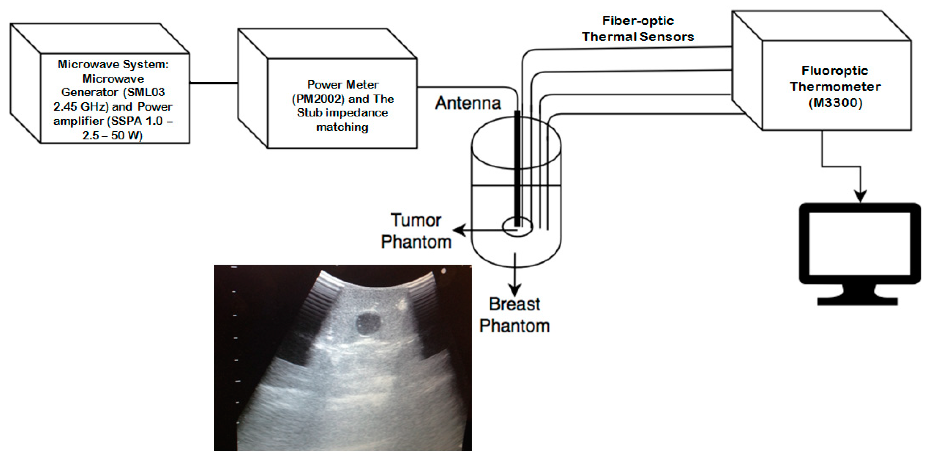
According to [47], fiber optic sensors present advantages including their small size and low cost. In contrast to electrical measurements, where the difference of two absolute potentials must be measured, and fiber optics are self-contained and do not require an external reference signal. Because the signal is optical, there is no electrical risk to the patient, and there is no direct interference from surrounding electric or magnetic fields. Kapranov and Kouzaev [48] justified that IR and fiber optic sensors may be more reliable measurements at powers of 10W. For this the reason, a non-interfering thermometry system that comprises four Luxtron fiber-optic thermal probes, a fluoroptic thermometer (M3300) was used to measure the real-time temperature during the microwave ablation (MWA) experiments. Temperature data were stored every second. Fiber-optic thermal probes do not interfere with microwave radiation. These sensors were Luxtron STB MAR05 and they were placed inside glass capillaries to ensure their position, placed by the side of the slot antenna, in each experimental run. Figure 2 depicts a scheme of the experimental setup; it comprises the radiation and thermometry systems, and ultrasound image equipment to localize the tumor phantom inside the healthy breast phantom. Four thermal probes were inserted inside the phantom along the side of the antenna, as shown in Figure 2.

3. Results

FEM models and antenna behavior in phantom experimentation were compared. A total of 10 W input power were applied for 4 min. Each analyzed antenna was inserted at the midpoint of the tumor phantom.

3.1. FEM Thermal Distributions Results

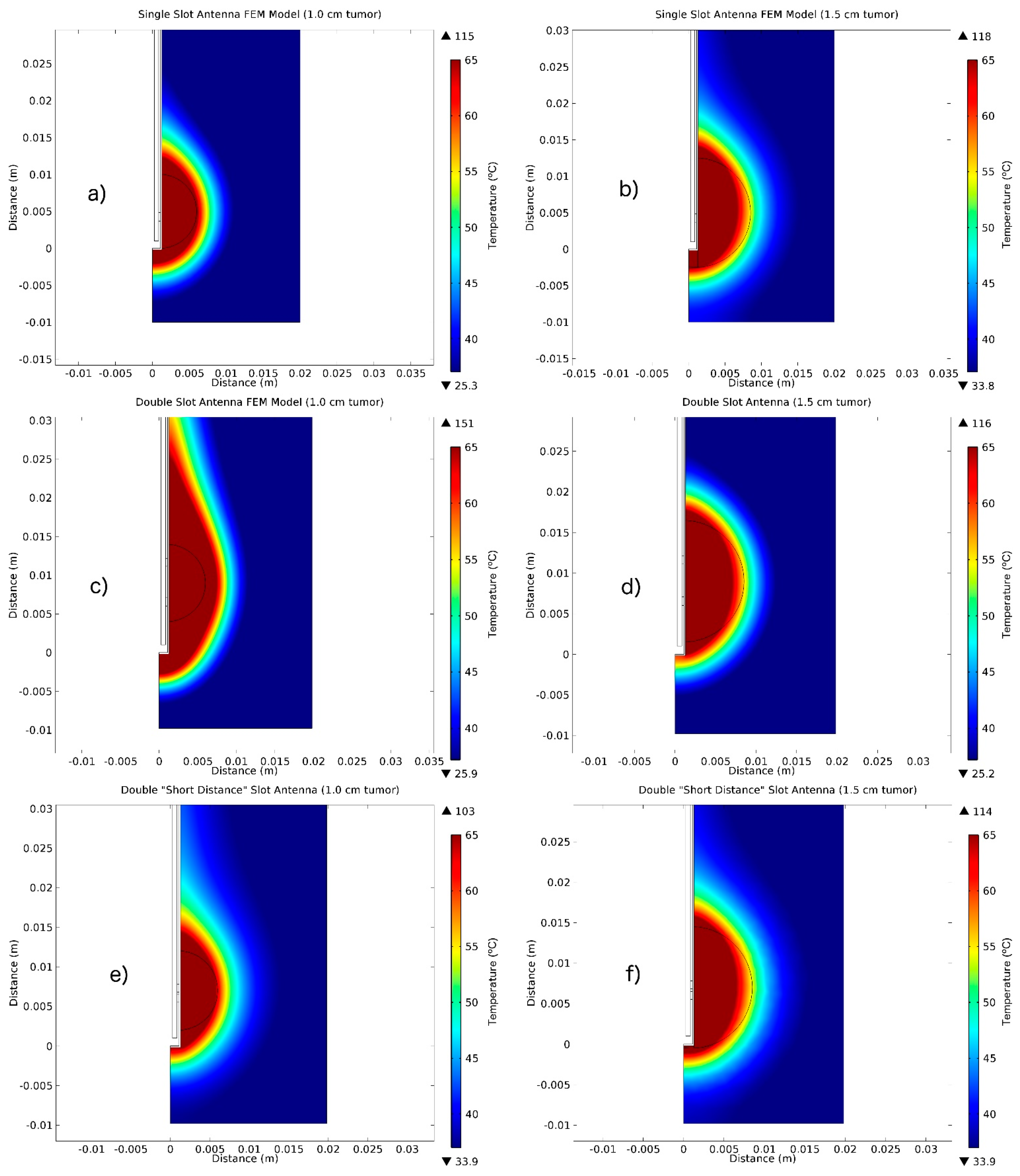
Figure 3 shows the temperature distribution in tumor tissue surrounded by breast tissue generated by each of the three types of micro-coaxial slot antennas (single, double and double “short distance”). According to these results, antenna geometry and tumor dimension modify the thermal pattern. Figure 3a,b show thermal distribution using the single slot antenna inside a 1.0 cm and 1.5 diameter sphere-shaped tumor. For a 1 cm tumor, the ablation area (above 60 °C) was 197.92 mm2 (radius of 7.94 mm), while for a 1.5 cm tumor, the area was 238.76 mm2 (radius of 8.74 mm). Figure 3c,d show the thermal distribution obtained with the double slot antenna in 1.0 and 1.5 cm diameter tumors, respectively. The ablated areas (tissue over 60°C) were 371.10 mm2 (radius of 10.87 mm) and 244.73 mm2 (radius of 8.82 mm), respectively. Finally, Figure 3e,f show heat distribution using the double “short distance” slot antenna inside 1.0 and 1.5 cm diameter tumor phantoms, respectively. The ablated heated area corresponds to 160.69 mm2 (radius of 7.15 mm) and 232.47 mm2 (radius of 8.60 mm). As can be seen for all cases, the ablation temperature was reached in the tumor area. As can be seen in Figure 3, the tissue damage of each antenna presents different shapes, even when the dimensions of the tumor tissue change (1 and 1.5 cm). This would provide an alternative to performing thermal treatments focused on the dimensions and shape of the tumor to be treated.

3.2. Experimental Results: SWR Measurements.

The SWR measurements were carried out by using the single, double and double “short distance” antennas inserted in a tumor phantom surrounded by healthy tissue. Table 2 shows the SWR measured for each antenna. SWR is a parameter that describes impedance-matching between the antenna and the transmission line. SWR is always a real and positive number for antennas, in this case, coaxial slot antennas. The smaller the SWR is, the better the antenna is matched to the transmission line and the more power is delivered to the antenna. The ideal value of SWR is 1.0; in this case, no power is reflected from the antenna, which is ideal. Measurements made for the antennas show that the best result was found for the double “short distance” slot antenna with an SWR = 1.07.

3.3. Temperature Profiles

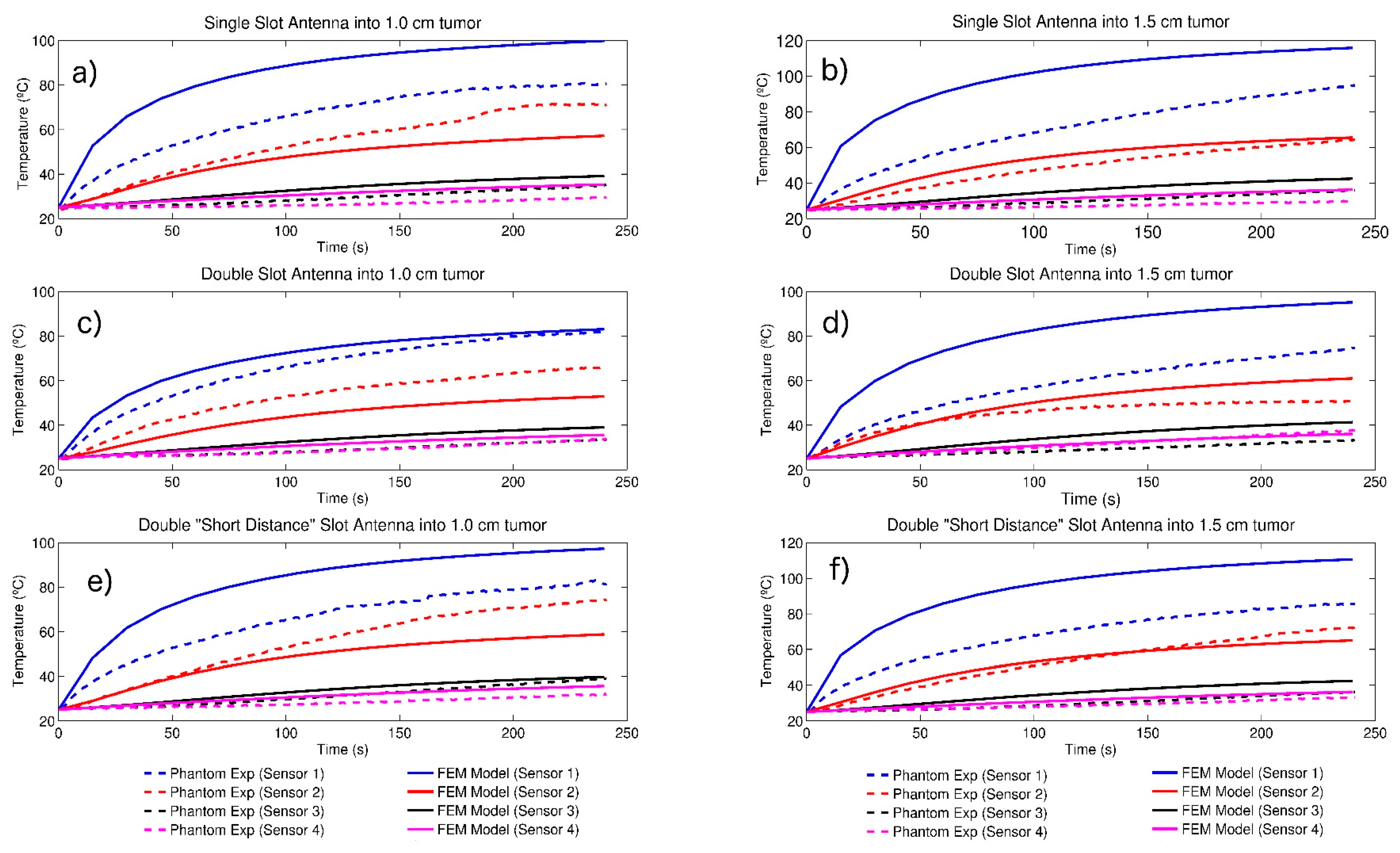
A comparison between the temperature increments measured during the phantom experimentation and those calculated by the FEM models is shown in Figure 4a–f. The four thermal sensors were placed alongside the slots. Sensor 1 was located at the slot antenna (single slot antenna) and in the middle of the distance between the two slots (double and double “short distance” slot antenna), sensor 2 was situated at 0.5 cm to sensor 1, sensor 3 and 4 were located at 1.0 and 1.5 cm from the antenna slot, respectively. As can be observed, there are differences in temperature increments for model and phantom experimentation. The smallest differences were found for the double slot antenna inserted in a 1.0 cm diameter phantom (Figure 4c); however, temperature increase was less than the one achieved in the other cases. For a 1 cm tumor, using the three types of antennas (Figure 4a,c,d), sensor 2 presented a higher temperature behavior in phantom experimentation than in the FEM model. The single slot antenna inserted in the tumor of 1.5 cm diameter (Figure 4b) showed the highest temperature reached in the sensor placed in the slot of the antenna (sensor 1) for both cases: FEM model and experimentation. Figure 4d shows the temperature profiles for double slot antenna inside a 1.5 cm diameter tumor. In this case, sensor 2 reached the highest temperature for the FEM model and phantom experimentation.
Table 3 presents the maximum temperatures measured by the four thermal sensors alongside the slot antenna for single, double and double “short distance” slot antennas inside the sphere-shaped tumor phantoms surrounded by the breast tissue. The tumor phantom was analyzed at two different diameter dimensions, 1.0 and 1.5 cm. The initial temperature was set at 25 °C and the temperature increases achieved for the computational model in sensor 1 were from 83.13 °C (ΔT 58.13 °C for double slot antenna inside the tumor of 1.0 cm) to 115.87 °C (ΔT 90.87 °C for single slot antenna inside the tumor of 1.5 cm) for FEM model and from 74.67 °C (ΔT 49.67 °C for double slot antenna inside the tumor of 1.5 cm) to 94.87 °C (ΔT 69.87 °C for single slot antenna inside the tumor of 1.5 cm) for phantom experimentation. It should be noted that the temperature increases achieved in sensor 4 (further from the antenna) were from 35.32 °C (ΔT 10.32 °C for single slot antenna inside the tumor of 1.0 cm) to 36.33 °C (ΔT 11.33 °C for double “short distance” slot antenna inside the tumor of 1.5 cm) for FEM model and from 29.72 °C (ΔT 4.72 °C for single slot antenna inside the tumor of 1.0 cm) to 33.73 °C (ΔT 8.73 °C for double slot antenna inside the tumor of 1.0 cm) for phantom experimentation. If body temperature is considered, the ΔT reached in sensor 4 were within the range of hyperthermia, so they would also cause a thermal effect in tissues.

4. Discussion and Conclusions

In this study, single coaxial slot, double, and double “short distance” coaxial slot antennas were analyzed. Using the finite element method (FEM), three types of coaxial slot antennas were modeled to estimate the heat transfer inside tumor tissue surrounded by healthy breast tissue. The antennas were constructed, and their behavior was experimentally evaluated in sphere-shaped tumor phantoms surrounded by breast phantoms. Two different sizes of tumor phantom were analyzed, 1.0 and 1.5 cm in diameter. A microwave radiation system was used to apply microwave energy into the phantom, and a non-electromagnetic interfering thermometry system was used to measure the temperature during the experimentation. The coaxial slot antennas were inserted into the phantom and microwave radiation was applied at 10 W for 240 s. The temperature inside the phantoms was measured by fiber-optic thermal probes every second.
In the FEM model presented in this paper, we used the biological heat transfer equation, Equation (6), proposed by Pennes [49], which describes the balance between the heat transfer of perfused tissues, heat losses from blood flow, metabolic heat from heating, and energy deposition. The FEM model and phantom experimentation helped us to validate the microwave therapy in relation to its potential, restrictions, and patient protection prior to implementation in medical practice. We found some differences between the models and the experimentation; we think that they are caused by losses in energy of the experimentation system, due to phantom’s water-based composition and the temperature dependence of the dielectric properties, which causes the temperature to be lower than in the model. The precision in the position of the thermal probes could also influence the results in the model; the results were taken at a precise point, whereas, in the experimental setup there may have been variations in their placement. Finally, the model considers ideal conditions, which were not possible to reach in the experimental phase. However, it is important to mention that, despite the temperature differences, the more important is that it was possible to obtain temperatures over 60°C after 240 s, which means that tissue ablation was achieved in all cases. According to Ekstrand [50], ablation therapy is produced above 60 °C; between 43 and 60 °C, the cell damage is the result of the denaturation of proteins. Over 60 °C, the cell death is considered almost instantaneous. When the tissue temperature reaches between 90 to 110 °C, phase transformation of the intra- and extra-cellular liquids occurs [18].
From this comparison, it was concluded that, in all cases for the model, ablation temperatures were reached (over 60 °C) and the tumor volumes considered in this study for tumor phantom spheres of 1.0 and 1.5 cm in diameter, were covered. As occurs in the model, 1 cm tumor phantom experimentation reached ablation temperatures in all tumor tissue areas. However, 1.5 cm tumor phantom experimentation thermal ablation covered a radius of 0.55 mm for single slot antenna, 0.31 mm for double slot antenna and 0.61 mm for double "short-distance" slot antenna. The temperatures obtained into the tumor phantom edge were 48.67, 43.15 and 57.77 °C for the single, double and double "short-distance" coaxial antenna, respectively. It should be noted that the temperatures at the edges of the tumor phantoms achieve hyperthermia therapy temperatures. Another consideration to take into account is that the initial temperatures of the experimentation were at room temperature (25 °C), able to achieve higher temperatures if body temperature (37 °C) is considered. The treatment area generated by the antennas was well-defined which allowed the damaging of less healthy tissue. Due to their small dimensions, these antennas may be less disruptive to the contour of the breast compared to conventional treatments, s they represent an excellent alternative to breast cancer treatment. Even though differences in experimental and modeling results were found in all cases, ablation temperatures were always reached; this encouraged us to test these antennas in cell cultures and in animal tissues, ex vivo and in vivo [51].

Author Contributions

Conceptualization, A.V.H., M.F.J.C.-R. and L.L.; methodology, A.V.H., M.F.J.C.-R. and R.O.-P.; investigation, R.O.-P.; resources, A.V.H. and L.L.; writing—original draft preparation, R.O.-P.; writing—review and editing, C.J.T.-R., M.F.J.C.-R. and A.V.H. All authors have read and agreed to the published version of the manuscript.

Funding

This research received no external funding.

Acknowledgments

Authors thank J. H. Zepeda Peralta for his important technical assistance. Authors would like to thank the National Council for Science and Technology (CONACYT, Mexico) for the support received with project CONACYT-Salud 2013-I; 201590, 201256, Joint Cooperation Mexico-Uruguay (SRE-AUCI) 2012–2013.

Conflicts of Interest

The authors declare no conflict of interest.

References

  1. Siegel, R.L.; Miller, K.D.; Jemal, A. Cancer statistics, 2016. CA Cancer J. Clin. 2016, 66, 7–30. [Google Scholar] [CrossRef] [PubMed] [Green Version]
  2. Bray, F.; Ren, J.S.; Masuyer, E.; Ferlay, J. Global estimates of cancer prevalence for 27 sites in the adult population. Int. J. Cancer 2013, 132, 1133–1145. [Google Scholar] [CrossRef] [PubMed]
  3. Hung, W.K.; Ying, M.; Chan, C.M.; Lam, H.S.; Mak, L. Minimally invasive technology in the management of breast disease. Breast Cancer 2009, 16, 23–29. [Google Scholar] [CrossRef] [PubMed]
  4. Pathak, S.; Jones, R.; Tang, J.M.F.; Parmar, C.; Fenwick, S.; Malik, H.; Poston, G. Ablative therapies for colorectal liver metastases: A systematic review. Colorectal Dis. 2011, 13, e252–e265. [Google Scholar] [CrossRef] [PubMed]
  5. Thomas, J.V.; Nagy, N.N. Naguib; Thomas, L.; Nour-Eldin, A.N.-E. Radiofrequency, microwave, and laser ablation of pulmonary neoplasms: Clinical studies and technical considerations. Eur. J. Radiol. 2009, 15, 290–296. [Google Scholar]
  6. Vogel, T.J.; Farshid, P.; Naguib, N.N.; Zangos, S. Thermal ablation therapies in patients with breast cancer liver metastases: A review. Eur. Radiol. 2013, 23, 797–804. [Google Scholar] [CrossRef]
  7. Carrafiello, G.; Fontana, F.; Cotta, E.; Petullà, M.; Brunese, L.; Mangini, M.; Fugazzola, C. Ultrasound-guided thermal radiofrequency ablation (RFA) as an adjunct to systemic chemotherapy for breast cancer liver metastases. Radiol. Med. 2011, 116, 1059–1066. [Google Scholar] [CrossRef]
  8. Simon, C.J.; Dupuy, D.E.; Mayo-Smith, W.W. Microwave ablation: Principles and applications. Radio Graph. 2005, 25, S69–S83. [Google Scholar] [CrossRef]
  9. Safarik, I.; Safarikova, M. Magnetic nanoparticles in biosciences. Monatschefte Chem. 2002, 133, 737–759. [Google Scholar]
  10. Saiyed, Z.M.; Telang, S.D.; Ramchand, C.N. Application of magnetic techniques in the field of drug discovery and biomedicine. BioMagn. Res. Technol. 2003, 1, 2. [Google Scholar] [CrossRef] [Green Version]
  11. Diederich, C.J. Thermal ablation and high-temperature thermal therapy: Overview of technology and clinical implementation. Int. J. Hyperth. 2005, 21, 745–753. [Google Scholar] [CrossRef] [PubMed]
  12. Garrean, S.; Hering, J.; Saied, A.; Hoopes, P.J.; Helton, W.S.; Ryan, T.P.; Espat, N.J. Ultrasound monitoring of a novel microwave ablation MWA) device in porcine liver: Lessons learned and phenomena observed on ablative effects near major intrahepatic vessels. J. Gastrointest. Surg. 2009, 13, 334–340. [Google Scholar] [CrossRef] [PubMed]
  13. Keangin, P.; Rattanadecho, P.; Wessapan, T. An analysis of heat transfer in liver tissue during microwave ablation using single and double slot antenna. Int. Commun. Heat Mass Transf. 2011, 38, 757–766. [Google Scholar] [CrossRef]
  14. Correa-Gallego, C.; Fong, Y.; Gonen, M.; D’Angelica, M.I.; Allen, P.J.; DeMatteo, R.P.; Jarnagin, W.R.; Kingham, T.P. A Retrospective Comparison of microwave Ablation vs. Radiofrequency Ablation for Colorectal Cancer Hepatic Metastases. Ann. Surg. Oncol. 2014, 21, 4278–4283. [Google Scholar] [CrossRef] [Green Version]
  15. Brace, C.L. Radiofrequency and microwave ablation of the liver, lung, kidney, and bone: What are the differences? Curr. Probl. Diagn. Radiol. 2009, 38, 135–143. [Google Scholar] [CrossRef] [Green Version]
  16. Laeseke, P.F.; Lee, F.T.; Sampson, L.A.; Van der Weide, D.W.; Brace, C.L. Microwave Ablation versus Radiofrequency Ablation in the kidney. J. Vasc. Interv. Radiol. 2009, 20, 1224–1229. [Google Scholar] [CrossRef] [Green Version]
  17. Martin, R.C.; Scoggins, C.R.; McMasters, K.M. Safety and efficacy of microwave ablation of hepatic tumors: A prospective review of a 5-year experience. Ann. Surg. Oncol. 2010, 17, 171–178. [Google Scholar] [CrossRef]
  18. Brace, C.L.; Hinshaw, J.L.; Laeseke, P.F.; Sampson, L.A.; Lee, F.T. Pulmonary thermal ablation: Comparison of radiofrequency and microwave devices by using gross pathologic and CT findings in a swine model. Radiology 2009, 251, 705–711. [Google Scholar] [CrossRef] [Green Version]
  19. Cavagnaro, M.; Amabile, C.; Bernardi, P.; Pisa, S.; Tosoratti, N. A minimally invasive antenna for microwave ablation therapies: Design, performances, and experimental assessment. IEEE Trans. Biomed. Eng. 2011, 58, 949–959. [Google Scholar] [CrossRef]
  20. Brace, C.L. Dual-slot antennas for microwave tissue heating: Parametric design analysis and experimental validation. Med. Phys. 2011, 38, 4232–4240. [Google Scholar] [CrossRef] [Green Version]
  21. Cavagnaro, M.; Amabile, C.; Bernardi, P.; Pisa, S.; Tosoratti, N. Design and realization of a new type of interstitial antenna for ablation therapies. In Proceedings of the IEEE 39th 2009 European Microwave Conference (EuMC), Rome, Italy, 29 September–1 October 2009; pp. 878–881. [Google Scholar]
  22. Bertram, J.M.; Yang, D.; Converse, M.C.; Webster, J.; Mahvi, D. Antenna design for microwave hepatic ablation using an axisymmetric electromagnetic model. BioMed. Eng. OnLine 2006, 5, 15–24. [Google Scholar] [CrossRef] [PubMed] [Green Version]
  23. Saito, K.; Yoshimura, H.; Ito, K.; Aoyagi, Y.; Horita, H. Clinical trials of interstitial microwave hyperthermia by use of coaxial slot antenna with two slots. IEEE Trans. Microw. Theory Tech. 2004, 52, 1987–1991. [Google Scholar] [CrossRef]
  24. Bernardi, P.; Cavagnaro, M.; Lin, J.C.; Pisa, S.; Piuzzi, E. Distribution of SAR and temperature elevation induced in a phantom by a microwave cardiac ablation catheter. IEEE Trans. Microw. Theory Tech. 2004, 52, 1978–1986. [Google Scholar] [CrossRef]
  25. Zhang, H.; Nan, Q.; Liu, Y. SAR distribution of microwave antenna for atrial fibrillation catheter ablation. In Proceedings of the 5th International Conference on Biomedical Engineering and Informatics (BMEI), Chongqing, China, 16–18 October 2012; pp. 664–667. [Google Scholar]
  26. Chaichanyut, M. Microwave ablation with cap-choke antenna: Result in computer simulation. In Proceedings of the ECTI International Conference on Electrical Engineering/Electronics, Computer, Telecommunications and Information Technology ECTI-CON2010, Chiang Mai, Thailand, 19–21 May 2010; pp. 679–682. [Google Scholar]
  27. Cepeda, M.F.; Vera, A.; Leija, L. Coaxial antenna for microwave coagulation therapy in ex vivo swine breast tissue. In Proceedings of the 7th International Conference on Electrical Engineering Computing Science and Automatic Control (CCE), Tuxtla Gutierrez, Mexico, 8–10 September 2010; pp. 268–273. [Google Scholar]
  28. Ortega-Palacios, R.; Vera, A.; Leija, L. Microwave Ablation Coaxial Antenna Computational Model Slot antenna comparison. In Proceedings of the 2012 Pan American Health Care Exchanges (PAHCE), Miami, FL, USA, 26–31 March 2012; pp. 112–115. [Google Scholar]
  29. Lopez Luna, J.F. Optimización de la Energia Entregada por un Aplicador de Doble Ranura Microaxial Para Tratamiento de Cancer de Mama Mediante Ablacion por Microondas Modelado FEM, Validacion en Phantom y Experimentacion In vitro e In vivo. Master’s Thesis, Cinvestav, Mexico City, Mexico, 2015. [Google Scholar]
  30. Lara, J.E.; Vera, A.; Leija, L. Proposal for the application of microwave ablation as a treatment for breast cancer using interstitial applicators: Antenna design and FEM modeling. In Proceedings of the 2016 Global Medical Engineering Physics Exchanges/Pan American Health Care Exchanges (GMEPE/PAHCE), Madrid, Spain, 4–9 April 2016; pp. 1–6. [Google Scholar]
  31. Manzanárez, A.; Lara, J.E.; Vera, A.; Leija, L.; Gutiérrez, M.I. Influence of the surrounding tissues in the radiation pattern of microcoaxial antenna for the treatment of breast tumors. In Proceedings of the 13th International Conference on Electrical Engineering, Computing Science and Automatic Control (CCE), Mexico City, Mexico, 26–30 September 2016; pp. 1–6. [Google Scholar]
  32. Ortega-Palacios, R.; Trujillo-Romero, C.J.; Cepeda Rubio, M.F.J.; Vera, A.; Leija, L.; Reyes, J.L.; Ramírez-Estudillo, M.C.; Morales-Alvarez, F.; Vega-López, M.A. Feasibility of Using a Novel 2.45GHz Double Short Distance Slot Coaxial Antenna for Minimally Invasive Cancer Breast Microwave Ablation Therapy: Computational Model, Phantom, and In Vivo Swine Experimentation. J. Healthc. Eng. 2018. [Google Scholar] [CrossRef] [Green Version]
  33. Nan, Q.; Guo, X.M.; Zhai, F. The Contrast of Two Kinds of Microwave Antenna SAR Simulation. Appl. Mech. Mater. 2014, 553, 379–383. [Google Scholar] [CrossRef]
  34. Cepeda Rubio, M.F.J.; Vera, A.; Leija Salas, L. Applicator Design for Microwave Ablation in Breast Cancer. In Proceedings of the International Microwave Proceedings of 43rd Annual Microwave Symposium, Washington, DC, USA, 8–10 July 2009; pp. 54–59. [Google Scholar]
  35. Cepeda Rubio, M.F.J.; Vera, A.; Leija Salas, L.; Ávila-Navarro, E.; Navarro, E.A. Coaxial Slot Antenna Design for Microwave Hyperthermia using Finite-Difference Time-Domain and Finite Element Method. Open Nanomed. J. 2011, 3, 2–9. [Google Scholar] [CrossRef] [Green Version]
  36. Navarro, E.A.; Wu, C.; Chung, P.Y.; Litva, J. Some considerations about the FDTD method in General Curvilinear Coordinates. IEEE Microw. Guided Wave Lett. 1994, 7, 396–398. [Google Scholar] [CrossRef]
  37. Reig, C.; Navarro, E.A.; Such, V. Calculation of the characteristic impedance of microstrips using a full-wave 2-D FDTD scheme. Microw. Opt. Technol. Lett. 1997, 16, 58–60. [Google Scholar] [CrossRef]
  38. Reig, C.; Navarro, E.A.; Such, V. Full-wave FDTD design and analysis of wideband microstrip-to-waveguide transitions. Microw. Opt. Technol. Lett. 2003, 38, 317–320. [Google Scholar] [CrossRef]
  39. Blanchard, C.; Portí, J.A.; Morente, J.A.; Salinas, A.; Navarro, E.A. Determination of the effective permittivity of dielectric mixtures with the transmission line matrix method. J. Appl. Phys. 2007, 102, 064101. [Google Scholar] [CrossRef] [Green Version]
  40. Sysoev, S.; Kislitsyn, A. Modeling of Microwave Heating and Oil Filtration in Stratum. In Numerical Simulations—Applications, Examples and Theory; Angermann, L., Ed.; InTech: London, UK, 2011; ISBN 978-953-307-440-5. [Google Scholar]
  41. Jin, J.-M.; Riley, D.J. Finite Element Analysis of Antennas and Arrays; John Wiley & Sons, Inc.: Hoboken, NJ, USA, 2009. [Google Scholar]
  42. Jiao, T.; Wang, H.; Zhang, Y.; Yu, X.; Xue, H.; Lv, H.; Wang, J. A coaxial-slot antenna for invasive microwave hyperthermia therapy. J. Biomed. Sci. Eng. 2012, 5, 198–202. [Google Scholar] [CrossRef] [Green Version]
  43. Gabriel, C. Compilation of the Dielectric Properties of Body Tissues at Rf and Microwave Frequencies; Technical Report No. AL/OETR-1996-0037; Brooks Air Force Base: San Antonio, TX, USA, 1996. [Google Scholar]
  44. García-Jimeno, S.; Ortega-Palacios, R.; Cepeda-Rubio, M.; Vera, A.; Leija, L.; Estelrich, J. Improved thermal ablation efficacy using magnetic nanoparticles: A study in tumor phantoms. Prog. Electromagn. Res. 2012, 128, 229–248. [Google Scholar] [CrossRef] [Green Version]
  45. Trujillo-Romero, C.J.; Leija, L.; Vera, A. FEM modeling for performance evaluation of an electromagnetic oncology deep hyperthermia applicator when using monopole, inverted T, and plate antennas. Prog. Electromagn. Res. 2011, 120, 99–125. [Google Scholar] [CrossRef] [Green Version]
  46. Trujillo-Romero, C.J.; García-Jimeno, S.; Vera, A.; Leija, L.; Estelrich, J. Using nanoparticles for enhancing the focusing heating effect of an external waveguide applicator for oncology hyperthermia: Evaluation in muscle and tumor phantoms. Prog. Electromagn. Res. 2011, 121, 343363. [Google Scholar] [CrossRef] [Green Version]
  47. Bronzino, J.D. Medical Devices and Systems; The Biomedical Engineering Handbook; CRC Press: Boca Raton, FL, USA, 2006. [Google Scholar]
  48. Kapranov, S.; Kouzaev, G. Study of microwave heating of reference liquids in a coaxial waveguide reactor using the experimental, semi-analytical and numerical means. Int. J. Therm. Sci. 2019, 140, 505. [Google Scholar] [CrossRef]
  49. Pennes, H.H. Analysis of skin, muscle and brachial arterial blood temperatures in the resting normal human forearm. Am. J. Med. Sci. 1948, 215, 354. [Google Scholar]
  50. Ekstrand, V.; Wiksell, H.; Schultz, I.; Sandstedt, B.; Rotstein, S.; Eriksson, A. Influence of electrical and thermal properties on RF ablation of breast cancer: Is the tumour preferentially heated? BioMed. Eng. OnLine 2005, 4, 41. [Google Scholar] [CrossRef] [Green Version]
  51. Hernández, A.V.; Quero, J.E.C.; Salas, L.L.; Mier, Y.H.; Marchal, C. Hipertermia electromagnética, una alternativa para el tratamiento del cáncer: Antecedentes, aspectos físicos y biológicos. Rev. Mex. Ing. Bioméd. 2011, XXII, 78–88. [Google Scholar]
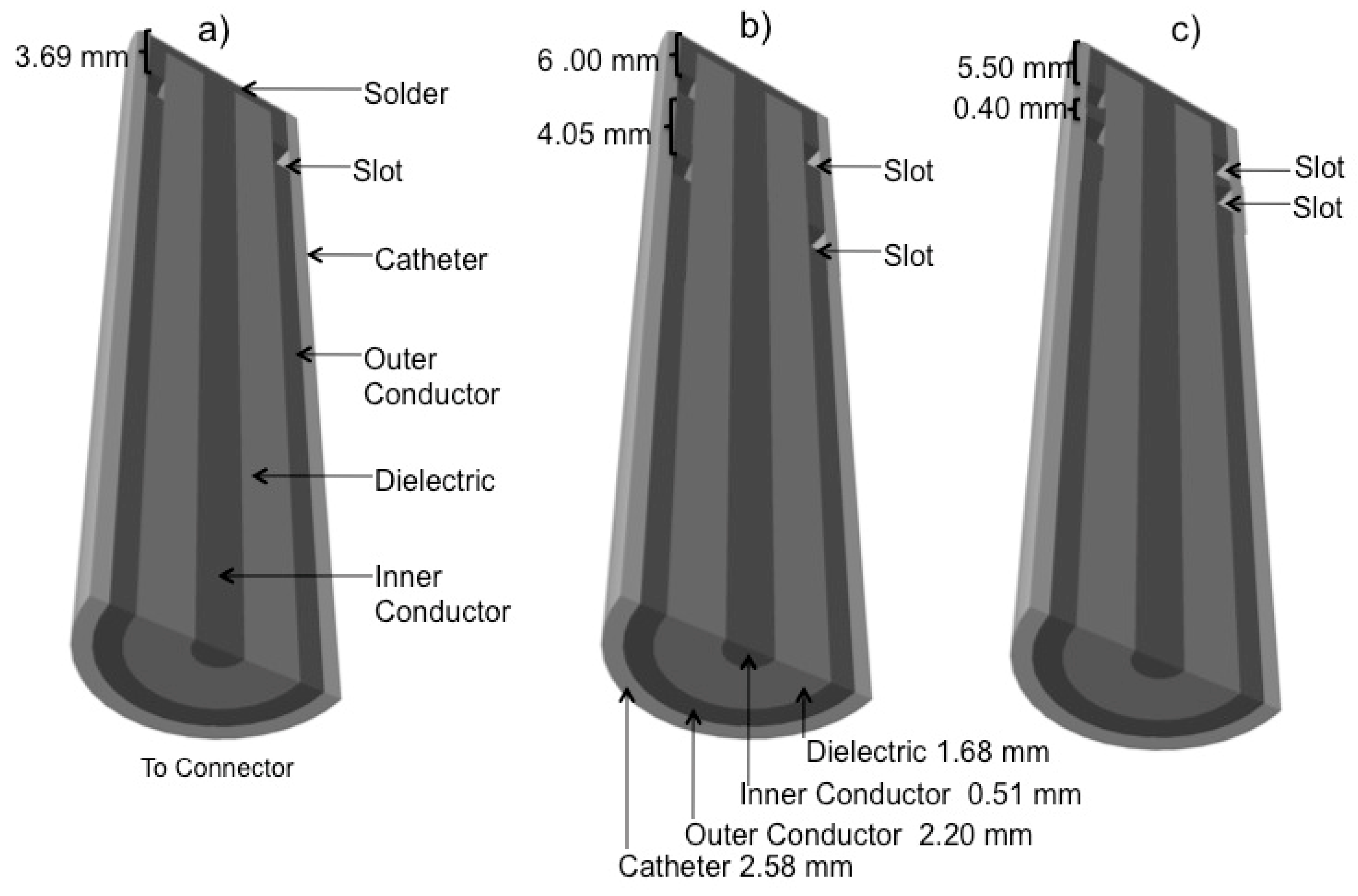
Figure 1. Coaxial Slot Antennas. (a) Single slot antenna; (b) Double slot antenna; (c) Double “short-distance” slot antenna.
Electronics 09 00535 g001
Figure 2. Phantom Experimental Setup. The radiation system supplied the microwave power to generate thermal ablation, while the non-interfering thermometry system measured the temperature increases inside the phantom every second during the experimentation.
Electronics 09 00535 g002
Figure 3. Thermal distributions obtained over tumor tissue surrounded by healthy breast tissue generated by the 2D axisymmetric FEM model. (a) Single slot antenna inserted in a 1.0 cm diameter tumor, (b) Single slot antenna inserted in a 1.5 cm diameter tumor phantom, (c) Double slot antenna inserted in a 1.0 cm diameter tumor, (d) Double slot antenna inserted in a 1.5 cm diameter tumor phantom, (e) Double “short distance” slot antenna inserted in a 1.0 cm diameter tumor and (f) Double “short distance” slot antenna inserted in a 1.5 cm diameter tumor phantom.
Electronics 09 00535 g003
Figure 4. Temperature distribution comparison in tumor tissue surrounded by breast tissue obtained from Phantom Experimentation and the FEM Model. Temperature comparison in thermal sensors were located alongside the slot antenna, the solid lines represent the FEM model results, while the dotted lines represents the experimental results during 240 s at 10 W of power. (a) Single slot antenna inside the 1.0 cm diameter tumor, (b) Single slot antenna inside the 1.5 cm-diameter tumor, (c) Double slot antenna inside the 1.0 cm diameter tumor, (d) Double slot antenna inside the 1.5 cm diameter tumor, (e) Double “short distance” slot antenna inside the 1.0 cm diameter tumor and (f) Double “short distance” slot antenna inside the 1.5 cm diameter tumor.
Electronics 09 00535 g004
Table 1. Tissue and antenna parameters used in the finite element method (FEM) model.
ParameterValue
Breast Electric Conductivity0.14 S/m
Breast Relative Permittivity5.14
Breast Thermal Conductivity0.42 W/Mk
Breast Density1020.00 Kg/m3
Tumor Electric Conductivity3.00 S/m
Tumor Relative Permittivity57.00
Tumor Thermal Conductivity0.50 W/mK
Tumor Density1041.00 Kg/m3
Blood Density1000 Kg/m3
Blood Specific Heat3639 J/(Kg K)
Blood Perfusion Rate0.0036 1/s
Blood Temperature37 °C
Dielectric Relative Permittivity2.03
Catheter Relative Permittivity2.60
Microwave Frequency2.45 GHz
Input Microwave Power10 W
Table 2. Coaxial slot antenna standing wave ratio (SWR) measurements.
AntennaSWR
Single Slot2.89
Double Slot1.84
Double “Short Distance” Slot1.07
Table 3. Maximum temperature in thermal sensors alongside the antenna for single, double and double “short distance” slot antennas in tumor phantom surrounded by breast tissue: computational model and phantom experimentation results (T1, T2, T3, and T4 were the thermal sensors placed at 0.0, 0.5, 1.0 and 1.5 cm from the antenna slot, respectively).
Tumor DimensionTemperature (°C) at 240 s
Single Slot AntennaComputational ModelPhantom Experimentation
T1T2T3T4T1T2T3T4
1.0 cmT
ΔT
99.88
74.88
57.20
32.2
39.16
14.16
35.32
10.32
80.89
55.89
71.62
46.62
35.12
10.12
29.72
4.72
1.5 cmT
ΔT
115.87
90.87
65.55
40.55
42.45
17.45
36.25
11.25
94.87
69.87
64.46
39.46
35.95
10.95
29.95
4.95
Double Slot Antenna
1.0 cmT
ΔT
83.13
58.13
52.91
27.91
39.03
14.03
35.61
10.61
81.93
56.93
66.14
41.14
34.01
9.01
33.73
8.73
1.5 cmT
ΔT
95.20
70.2
61.00
36.00
41.36
16.36
36.09
11.09
74.67
49.67
50.93
25.93
37.81
12.81
33.56
8.56
Double “Short Distance” Slot Antenna
1.0 cmT
ΔT
97.28
72.28
58.75
33.75
39.78
14.78
35.62
10.62
83.12
58.12
74.38
49.38
38.99
13.99
32.12
7.12
1.5 cmT
ΔT
110.58
85.58
65.57
40.57
42.52
17.52
36.33
11.33
85.78
60.78
72.50
47.50
36.35
11.35
33.43
8.43