High Voltage, Low Current High-Power Multichannel LEDs LLC Driver by Stacking Single-Ended Rectifiers with Balancing Capacitors


Abstract
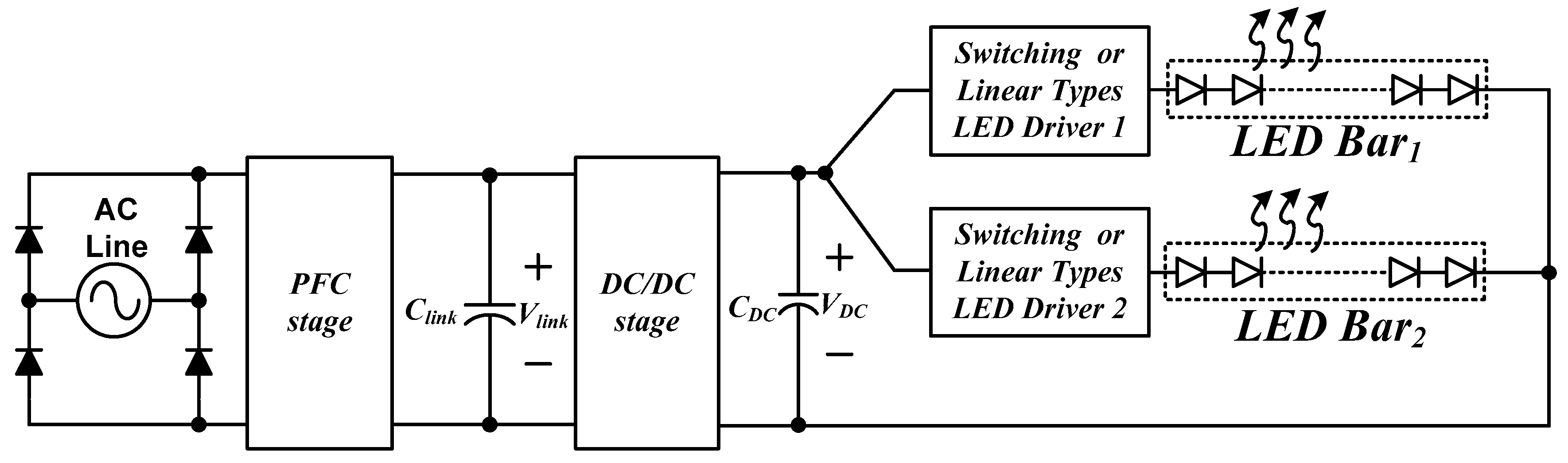
:1. Introduction
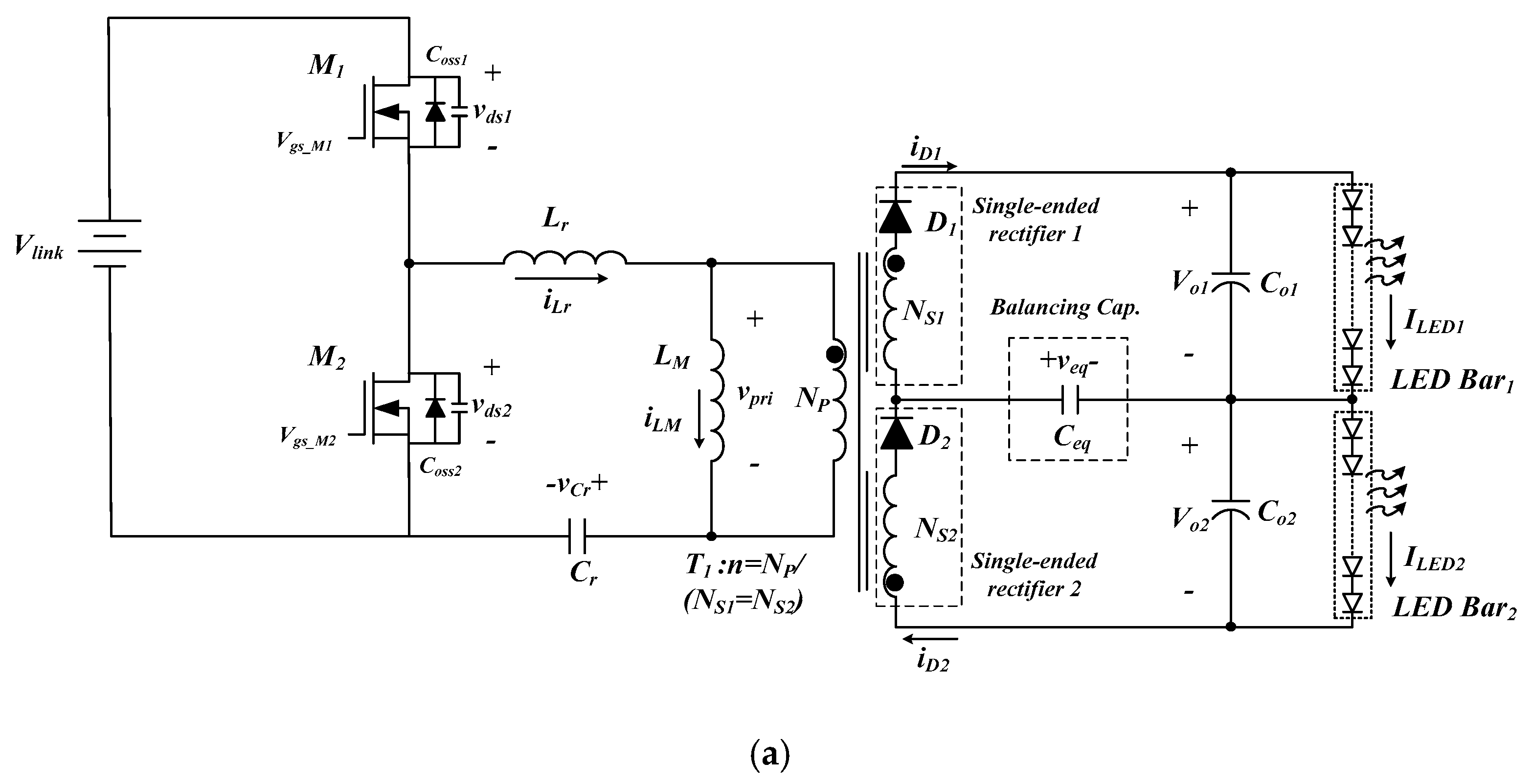
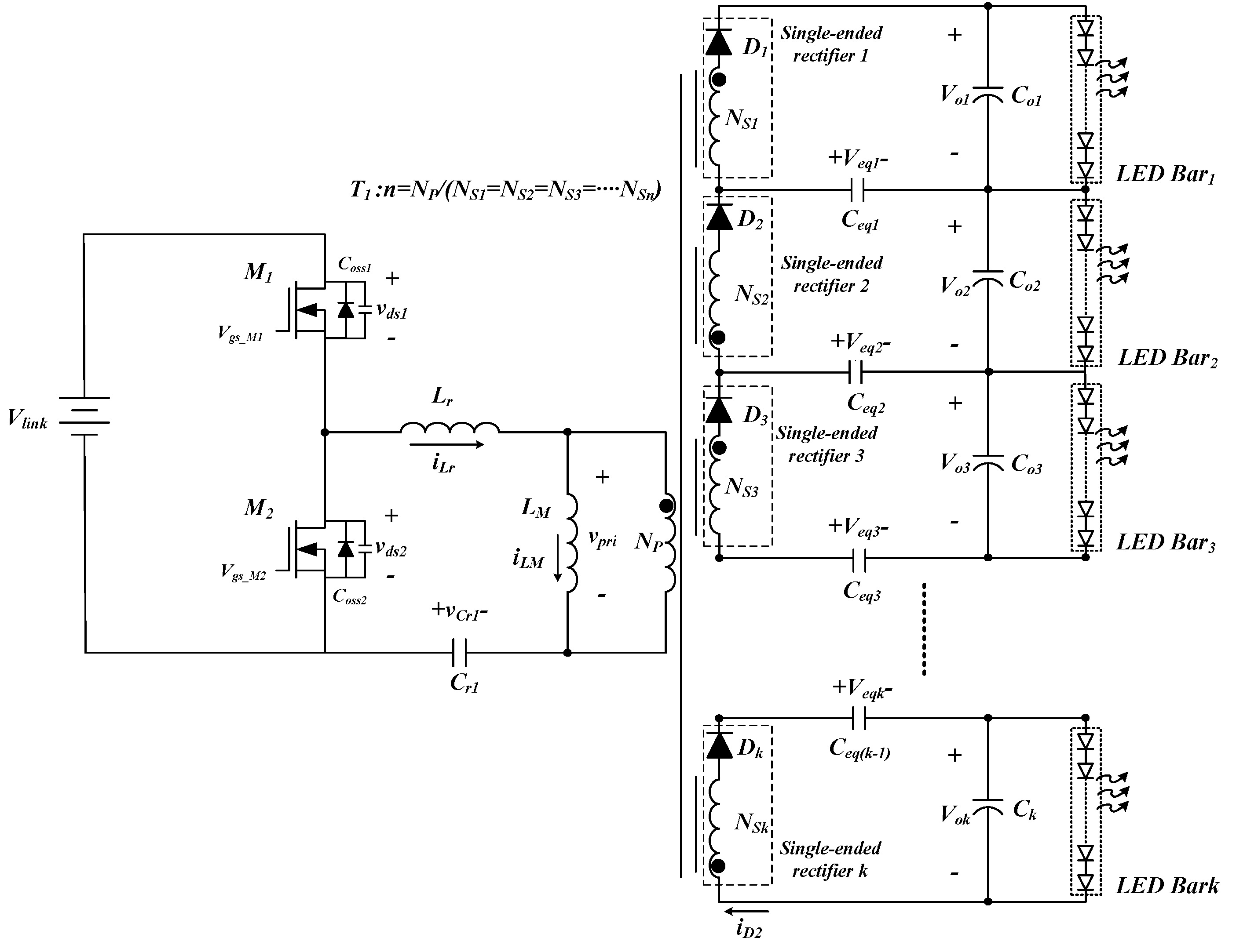
2. Proposed LLC LED Driver
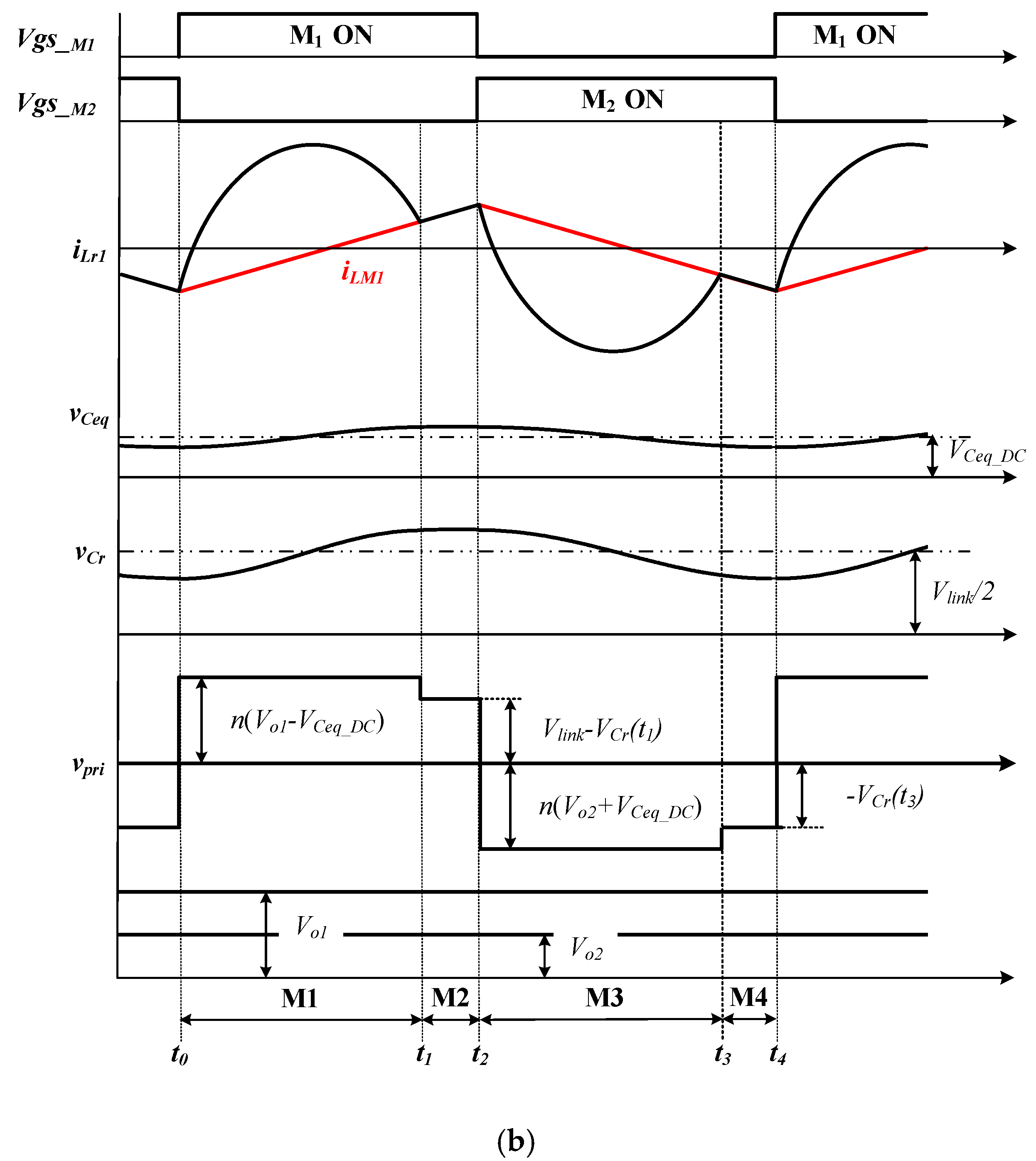
2.1. Modal Analysis
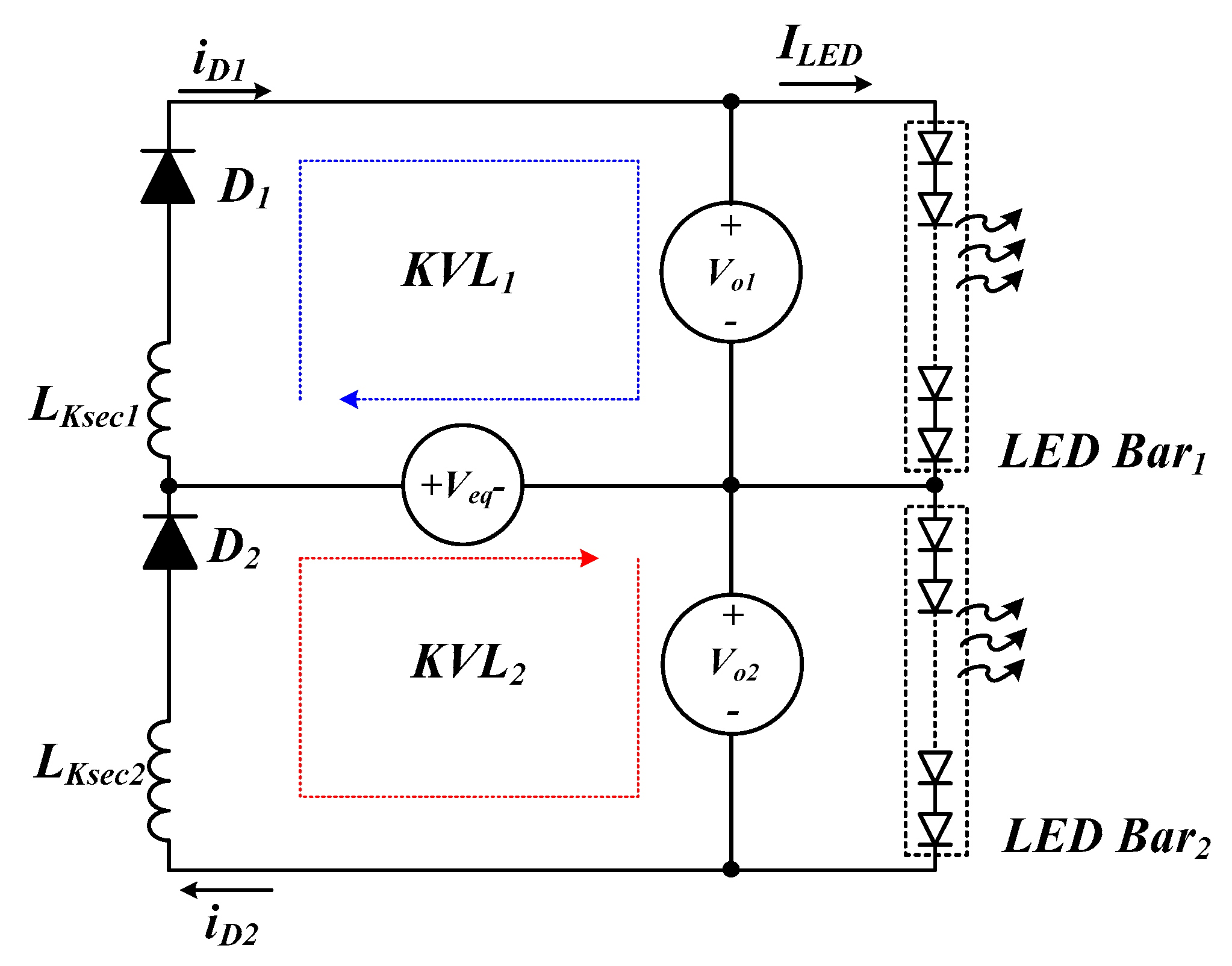
2.2. Current Balance Mechanism
2.3. Extension of the Proposed Circuit for Multichannel LEDs
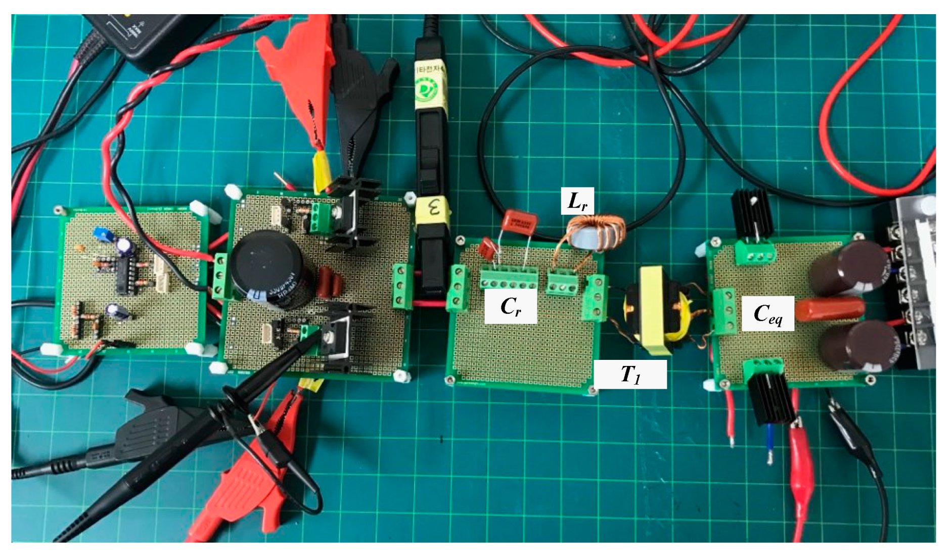
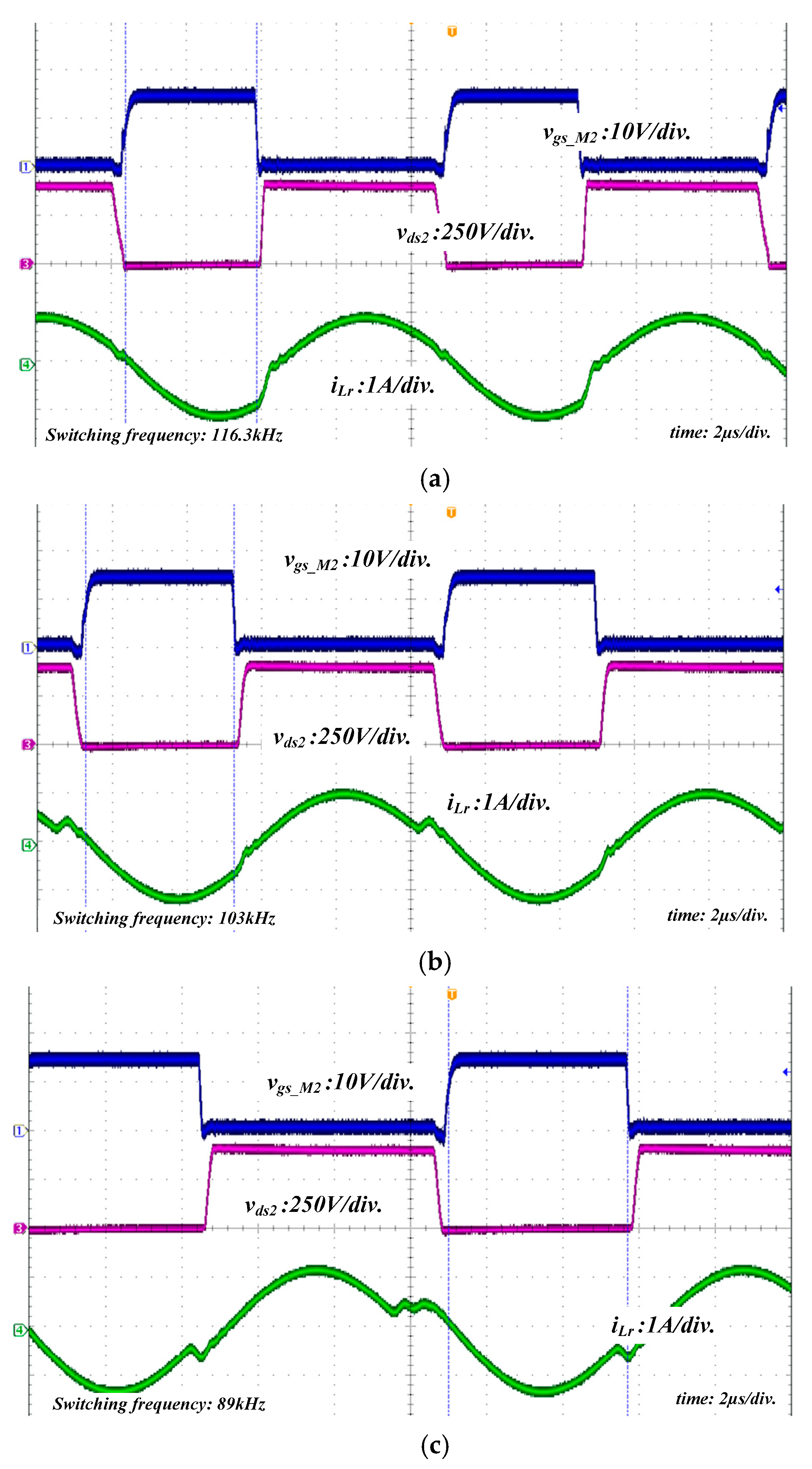
3. Experimental results
4. Conclusions
Funding
Conflicts of Interest
References
- Narendran, N.; Gu, Y. Life of LED-based white light sources. J. Display Technol. 2005, 1, 167–171. [Google Scholar] [CrossRef]
- Carraro, G. Solving high-voltage off-line HB-LED constant-current control-circuit issues. In Proceedings of the Applied Power Electronics Conference, Anaheim, CA, USA, 25 February–1 March 2007; pp. 1316–1318. [Google Scholar]
- Chiu, H.-J.; Lo, Y.-K.; Chen, J.-T.; Cheng, S.-J.; Lin, C.-Y.; Mou, S.-C. A high-efficiency dimmable LED driver for low-power lighting applications. IEEE Trans. Ind. Electron. 2010, 57, 735–743. [Google Scholar] [CrossRef]
- Jacobs, J.; Jie, S.; Hente, D. A simple digital current controller for solid-state lighting. In Proceedings of the Power Electronics Specialist Conference, Rhodes, Greece, 15–19 June 2008; pp. 2417–2422. [Google Scholar]
- Hwu, K.I.; Yau, Y.T. Applying one-comparator counter-based sampling to current sharing control of multi-channel LED strings. In Proceedings of the IEEE Applied Power Electronics Conference, Palm Springs, CA, USA, 21–25 February 2010; pp. 737–742. [Google Scholar]
- Hu, Q.; Zane, R. LED driver circuit with series-input-connected converter cells operating in continuous conduction mode. IEEE Trans. Power Electron. 2010, 25, 574–582. [Google Scholar]
- Gucin, T.N.; Frincan, B.; Biberoglu, M. A Series Resonant Converter-Based Multichannel LED Driver With Inherent Current Balancing and Dimming Capability. IEEE Trans. Power Electron. 2019, 34, 2693–2703. [Google Scholar] [CrossRef]
- Wang, R.; Zhang, J. A simple current balancing method for multi-output flyback LED driver. In Proceedings of the IEEE 2nd International Future Energy Electronics Conference, Taipei, Taiwan, 1–4 November 2015; pp. 1–5. [Google Scholar]
- Modepalli, K.; Parsa, L. A scalable n-color led driver using single inductor multiple current output topology. IEEE Trans. Power Electron. 2016, 31, 3773–3783. [Google Scholar] [CrossRef]
- Guo, Y.; Li, S.; Lee, A.T.L.; Tan, S.C.; Lee, C.K.; Hui, S.Y.R. AC-DC Single-Inductor Multiple-Output Led Drivers. Chinese Patent PCT/CN2015/077 290, 27 October 2016. [Google Scholar]
- Guo, Y.; Li, S.; Lee, A.T.L.; Tan, S.C.; Lee, C.K.; Hui, S.Y.R. Single-stage ac/dc single-inductor multiple-output led drivers. IEEE Trans. Power Electron. 2016, 31, 5837–5850. [Google Scholar] [CrossRef]
- Chen, H.; Zhang, Y.; Ma, D. A simo parallel-string driver ic for dimmable led backlighting with local bus voltage optimization and single time-shared regulation loop. IEEE Trans. Power Electron. 2012, 27, 452–462. [Google Scholar] [CrossRef]
- Luo, Q.; Zhi, S.; Zou, C.; Lu, W.; Zhou, L. An led driver with dynamic high-frequency sinusoidal bus voltage regulation for multistring applications. IEEE Trans. Power Electron. 2014, 29, 491–500. [Google Scholar] [CrossRef]
- Luo, Q.; Ma, K.; He, Q.; Zou, C.; Zhou, L. A single stage high frequency resonant ac/ac converter. IEEE Trans. Power Electron. 2017, 32, 2155–2166. [Google Scholar] [CrossRef]
- Wu, X.; Hu, C.; Zhang, J.; Qian, Z. Analysis and design considerations of LLCC resonant multi output DC/DC led driver with charge balancing and exchanging of secondary series resonant capacitors. IEEE Trans. Power Electron. 2015, 30, 780–789. [Google Scholar] [CrossRef]
- Chen, X.; Huang, D.; Li, Q.; Lee, F. Multichannel led driver with CLL resonant converter. IEEE J. Emerging Sel. Topics Power Electron. 2015, 3, 589–598. [Google Scholar] [CrossRef]
- Wu, H.; Ji, S.; Lee, F.C.; Wu, X. Multi-Channel Constant Current (MC3) LLC Resonant LED Driver. In Proceedings of the 2011 IEEE ECCE, Phoenix, AZ, USA, 17–22 Sepember 2011; pp. 2568–2575. [Google Scholar]
- Cho, S.H.; Lee, S.H.; Hong, S.S.; Oh, D.S.; Han, S.K. High-accuracy and cost-effective current-balanced multichannel led backlight driver using single-transformer. In Proceedings of the International Conference on Power Electronics & ECCE Asia, Jeju, Korea, 30 May–3 June 2011; pp. 520–527. [Google Scholar]
- Park, C.H.; Cho, S.H.; Jang, J.; Pidaparthy, S.K.; Ahb, T.; Choi, B. Average Current Mode Control for LLC Series Resonant DC-to-DC Converters. J. Power Electron. 2014, 14, 40–47. [Google Scholar] [CrossRef]


| [13] | [14] | [15] | [16,17] | [18] | Proposed | |
|---|---|---|---|---|---|---|
| Diode | 4k | 4k+2 | 4k | k* + 1 | 3k | k |
| MOSFET | 4 | 2 | 1 | 2 | 2 | 2 |
| Transformer | 1 | 1 | 1 with k outputs | k*/2 | 1 with k outputs | 1 with k outputs |
| Inductor | 2k + 2 | 2k + 4 | 2 | k* + 1 | 1 | 1 |
| Capacitor | 2k + 2 | 2k + 6 | 2k+2 | 3k*/2 | 3k/2 + 1 | 2k − 1 |
| Parameters | Symbol | Value/Part |
|---|---|---|
| Input voltage | Vlink | 400 V |
| LED Output power | Po | 260 W |
| Resonant inductor | Lr | 62 μH |
| Turn ratio | Np:Ns1:Ns2 | 1:1:1 |
| Magnetizing inductor | LM | 502.4 μH |
| Resonance capacitor | Cr | 28 nF |
| Balancing capacitor | Ceq | 2.2 uF |
| Primary switches | M1,2 | W13NK100Z |
| Diodes | D1,2 | 15ETH06FP |
| Transformer core | T1 | EI4035 |
| [13] | [14] | [15] | [16,17] | [18] | Proposed | |
|---|---|---|---|---|---|---|
| Power (W) | 200 | 130 | 150 | 27 | 140 | 260 |
| LED current (mA) | 350 | 670 | 350 | 1000 | 100 | 650 |
| The number of channel | 10 | 1 | 4 | 10 | 4 | 2 |
| Deviation of resistance of LEDs (%) | 6% | - | 35% | 10% | - | 20% |
| Efficiency (%) | >92% | 90% | 86% ~96.5% | 93% ~95% | 95% | >96% |
© 2020 by the author. Licensee MDPI, Basel, Switzerland. This article is an open access article distributed under the terms and conditions of the Creative Commons Attribution (CC BY) license (http://creativecommons.org/licenses/by/4.0/).
Share and Cite
Yi, K.H. High Voltage, Low Current High-Power Multichannel LEDs LLC Driver by Stacking Single-Ended Rectifiers with Balancing Capacitors. Electronics 2020, 9, 529. https://doi.org/10.3390/electronics9030529
Yi KH. High Voltage, Low Current High-Power Multichannel LEDs LLC Driver by Stacking Single-Ended Rectifiers with Balancing Capacitors. Electronics. 2020; 9(3):529. https://doi.org/10.3390/electronics9030529
Chicago/Turabian StyleYi, Kang Hyun. 2020. "High Voltage, Low Current High-Power Multichannel LEDs LLC Driver by Stacking Single-Ended Rectifiers with Balancing Capacitors" Electronics 9, no. 3: 529. https://doi.org/10.3390/electronics9030529
APA StyleYi, K. H. (2020). High Voltage, Low Current High-Power Multichannel LEDs LLC Driver by Stacking Single-Ended Rectifiers with Balancing Capacitors. Electronics, 9(3), 529. https://doi.org/10.3390/electronics9030529