Abstract
Assessing the flux linkage is an important feature for electric machines, including switched reluctance machines. However, sensor calibration errors and noise impose a problem known as drift, which is caused by the integration process used to estimate the flux linkage. This paper proposes a flux linkage estimation with a drift cancellation technique. The technique accounts for the switched reluctance machine’s working and driving principles. Simulation and experimental results are used to validate the proposed method. Additionally, a goodness-of-fit analysis is performed to support the outcomes. A factor of is found between the experimentally and simulation-estimated flux linkage. The results indicate that the method works properly and may be further used in control techniques and iron losses estimation.
1. Introduction
In the past years, switched reluctance machines (SRMs) have increasingly drawn attention for various applications, especially those that require wide speed range operation, such as wind power systems [1] and electric vehicles [2]. The increased activity with SRMs arises from their advantages in industry applications such as low cost, simple structure without windings or rare earth materials in the rotor, ease of construction, high ruggedness, good fault-tolerance ability, and wide speed range operation. However, SRMs also present some disadvantages inherent to their structure and drive principle, such as acoustic noise, high torque ripple, and elevated losses compared to other machines of the same segment. Mitigating these disadvantages has been the focus of many studies, as presented hereafter.
Knowing the stator flux linkage in SRMs is important for many tasks, such as in instantaneous torque control methods based on flux vector orientation [3] and in the assessment of iron losses in SRMs as in [4]. For instance, a classic instantaneous torque control method named direct torque control (DTC) is based on controlling the instantaneous torque and the flux vector magnitude. Some variations of the DTC method have recently been proposed in the literature. In [5] two torque control methods for SRMs are presented and compared, where one of the methods directly uses flux linkage estimation. The authors of [6] apply a fuzzy adaptive DTC, while the authors in [7] optimize the voltage vectors to minimize torque ripple. Furthermore, in [8] a variable flux reference is proposed to enhance the DTC method, and in [9] a model predictive DTC is proposed to reduce torque ripple in SRMs. However, none of these works focus on the difficulties encountered in implementing the method experimentally, such as sensor signal white noise and calibration offset that lead to drift and large flux estimation errors.
Signal drift is a known problem that has been confronted in numerous research fields. Particularly, the authors of [10] proposed an adaptive filter based on least mean square (LMS) for noise cancellation that diminishes the signal drift in electrocardiogram signals. In [11] a Kalman filter is used to cancel the drift and filter the measurement noise in fiber optic gyroscope drift signals. In [12] a Kalman filter is applied to a real-time RFID indoor positioning system to remove the position estimation drift. However, the computational effort is high in both cases, increasing the cost of the system and therefore reducing the interest for industrial mass production.
The drift problem is also encountered in the electric machine drives field. In [13], the authors proposed to cascade a fifth-order low-pass filter (LPF) with a high-pass filter (HPF) to estimate the stator flux linkage of a flux switching generator. The idea is to use the HPF to filter high-order harmonics and the LPFs to filter the drift. In some works, the authors presented some of the difficulties found while implementing DTC for permanent magnet synchronous machines (PMSMs). One of the problems conferred was the flux linkage estimation drift caused by the sensors’ offset error. For example, in [14] a comparison of several methods applied to PMSM flux linkage estimation is presented. The method with better efficiency is a closed loop integrator with a PI feedback. The method compensated the drifting but presented a long settling time. Seven flux estimation techniques are presented in [15]. The best scheme presented depends on a PLL and PI controller, but it has better performance with AC machines. Authors in [16] present a comparison between LPF with input compensation and corner frequency tuning, LPF with output compensation and corner frequency tuning, and an adaptive flux observer for stator resistance identification. The results showed that the observer enhances the flux estimator performance, however implementing an observer for SRMs would be cumbersome because of the highly nonlinear behavior of SRMs. The authors in [17] estimate the PMSM flux linkage effectively through the machine state variable model, but the same strategy would not present good performance for SRM applications because the highly nonlinear model would lead to large deviations between the real and estimated flux linkage. In [18,19], the authors solve the integration drift problem with a compensation based on orthogonal properties of waveforms in the stator reference frame. The authors of [20] present a new approach based on the model of the PMSM. The method considers the nonlinearities of the PMSM, but requires burdensome calculations and assumptions. A flux observer with a distortion-minimizing algorithm have been reported for estimating flux linkage in interior permanent magnet synchronous machines (IPMSMs) [21]. The observer is based on the current and voltage models and improved by a frequency-adaptive feature.
Considering the lack of detailed information in the literature regarding flux linkage estimation with drift cancellation for SRMs, this paper presents a new drift cancellation method that considers the driving and working principles of SRMs. The proposed method is inspired by those of the studied literature. The method is easy to implement, does not require large memory like lookup table methods, and does not require cumbersome computational effort.
Additionally, the method proposed in the current paper for real-time flux linkage estimation could be adapted for other machines, such as synchronous reluctance machines or other machines that have expected zero flux linkage at some point of the electric cycle. For instance, in [22] the authors propose a flux weakening control technique for synchronous reluctance motors using a flux saturation model for different operation points calculated offline, in which the control method could be enhanced by a high-performance online flux linkage estimation method such as the one proposed in this paper.
This work is divided as follows: In Section 2, the SRM working and driving principles are presented along with the dynamic model of the machine to prelude the drift presence. In Section 3, the drift occurrence is explained by contextualizing the scope of switched reluctance machines. Section 4 emphasizes the proposed flux linkage drift cancellation method algorithm. Section 5 brings an analysis of the experimental results. Finally, the findings are concluded in Section 6.
2. Switched Reluctance Machine Modeling and Principles
In order to understand the occurrence of the signal drift in SRMs, one must understand the characteristics of the machine and drive principles. To simplify the analysis, consider that there is no magnetic coupling between phases, the eddy currents and hysteresis losses are negligible, and the phase resistance is constant. Thus, the equivalent circuit for one SRM phase is derived as in Figure 1.
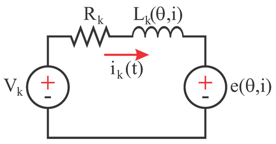
Figure 1.
Equivalent phase circuit of a switched reluctance machine (SRM) disregarding magnetic coupling and considering constant phase resistance.
From the equivalent circuit, the voltage equation for one SRM phase may be derived as in Equation (1), where , and are the terminal voltage, electric resistance, and current flowing in the phase k, and is the position () and current dependent flux linkage.
The second term of Equation (1) may be expanded, resulting in Equation (2), where is the phase k inductance and is the mechanical speed.
The instantaneous electromagnetic torque produced by one SRM phase () can be calculated as in Equation (3):
The total electromagnetic torque () produced by the machine is given by the sum of the torques produced by all phases as in Equation (4), where m is the number of phases:
The torque appears when voltage is applied to the phase terminals of the machine and tends to align the closest rotor pole to the energized stator pole. The coordination of this process leads to rotational acceleration.
3. Integration Drift
In SRMs, ideally, the flux linkage of each phase returns to zero at every electric cycle. Thus, is always equal to zero, as can be seen in Figure 2. Figure 2 shows the phase currents, voltages, and flux linkages of a three-phase SRM operating in hysteresis current control with soft-chopping. The reference current is fixed at A, while the hysteresis bands are ± A. The same setup was used hereafter in other simulations and in the performed experiments. The SRM used in the simulations and experiments has a nominal voltage and current of 30–80 V and A, respectively. All the simulations were performed using MATLAB/Simulink R2018a software.
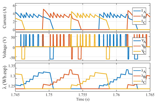
Figure 2.
Simulated ideal currents, voltages, and flux linkages of a three-phase SRM.
However, in order to estimate the flux linkage in real systems, current and voltage sensors must be used along with signal conditioning circuits. These sensors and circuits insert an offset and noise to the real current and voltage values. When this offset and noise are integrated through an electric cycle, the flux linkage does not return to zero and this error is carried to the next integration period as . This gradual change in the signal is known as drift, and may be either positive or negative depending on the offset between the real value and the sensed value.
For instance, consider an SRM operating in the same conditions as in Figure 2. Now let the current and voltage sensor signals have a low-power white noise added to it. Additionally, let an offset proportional to A ( of the nominal value) be added to the current sensor signal and an offset proportional to 2 V ( of nominal value) be added to the voltage sensor signal in order to simulate small errors in calibration as presented in Figure 3. If the same flux estimation technique is applied, the flux linkage signal drifts upward as presented in Figure 3. The drift variation depends directly on the offset amplitude and noise power. The long-term drift is caused by the offset, while the short-term variations are caused by the noise. Table 1 shows the flux linkage drift per second (Wb.esp/s) according to the electric current and terminal voltage offset, showing that higher values of offset lead to higher-order drifts in the calculated flux linkage.
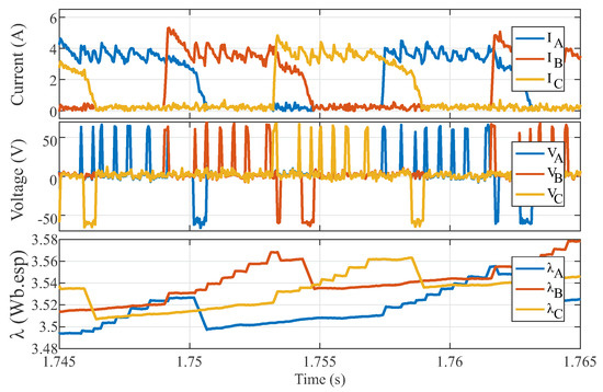
Figure 3.
Simulated sensed phase currents, voltages, and estimated flux linkages of a three-phase SRM with noise and calibration offset addition.

Table 1.
Signal drift according to offset amplitude.
There are several solutions for PMSM flux linkage signal drift presented in the literature [14,15,17]. The most basic solution is to take advantage of the cyclic behavior of the flux linkage and add a reset to the pure integrator at every cycle. Although this strategy mitigates the long-term drift, the drift still occurs between the reset cycles, implying that the method is not efficient during transients or highly dynamic operation. Additionally, the rotor position must be measured.
Another common solution is to use an LPF instead of an integrator for estimating the flux. However, this solution is not effective for SRM flux linkage estimation by itself because of the range of frequencies that compose the electric current and terminal voltage.
More complex solutions such as the extended Kalman filter (EKF) are widely applied to mitigate the signal drift problem. The EKF method is capable of eliminating a great part of the white noise influence and completely negates the drift problem, returning a signal with small error [11]. However, it requires knowledge of the machine model to predict the next state of the machine. In the case of SRMs, the model is highly nonlinear and complex, and thus the method requires more computational effort and becomes more challenging to design.
In this paper, a modification to the existing methods is proposed considering the SRM working principle and aiming to achieve straightforward implementation. Simulation and experimental results are presented and discussed to evaluate the method’s effectiveness.
3.1. Proposed Solution for the Drift Problem
In this section, the adaptations of some of the previously mentioned flux linkage estimation techniques for SRM as well as the proposed method are addressed. Simulation results are presented to evaluate the method’s performance.
3.1.1. Resettable Integrator
In order to implement the resettable integrator, a cyclical variable is needed. In this case, since the problem involves a rotational machine, the most reliable variable is the rotor position. The reset action must occur during the moment in which the expected value of flux linkage is zero. This moment may deviate according to the SRM operation (motor or generator), control technique implemented, and operation speed. Thus, the moment of the reset must be carefully chosen.
For a three-phase (number of stator/rotor poles) SRM, the electric cycle () is 45°. Considering that the inductance derivative is negative between 0° and 22.5° and positive in the other half of the electric cycle. For motor operation the phase should not be energized in the negative derivative of the inductance, that is, energization should occur only between 22.5° and 45°. However, depending on the control method applied, the phase might be energized slightly before or after this period.
For this reason, in this paper the integrator resets when the phase position relative to the rotor is greater than 18°; this angle is denoted hereafter.
A simulation was conducted in the same conditions presented in Section 3. The simulation results are presented in Figure 4. Note that the flux linkage signal was kept from drifting in the long term, but between the reset instants the drift still occurred, forcing the flux to deviate from zero according to the voltage and current offsets, which would lead to severe errors in iron loss estimation and control algorithms.
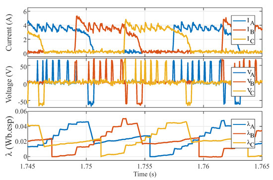
Figure 4.
Simulation results of estimated flux linkage using a resettable integrator.
3.1.2. Low-Pass Filters
As suggested in the literature [13], first-order low-pass filters can be applied as integrators with a gain for frequencies much higher than the cutoff frequency ().
The LPF filter structure for estimating the flux linkage is presented in Equation (6), where is the LPF open-loop transfer function, given by .
Figure 5a shows the estimated flux linkage for the three-phase SRM with different cutoff frequencies. From top to bottom, was set to 5000 rad/s, 500 rad/s, 5 rad/s, and rad/s. Figure 5b presents a detailed vision of the waveforms contained in the circled area of Figure 5a. The detail images are presented beside their originating figures.
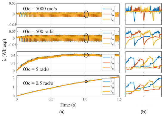
Figure 5.
(a) Simulation results of flux linkage estimation using low-pass filters (LPFs) with different cutoff frequencies; (b) Details on waveforms.
The flux linkage estimate is very sensitive to the choice of cutoff frequency. A low cutoff frequency will lead to an estimator with high settling time, which is undesirable. As the cutoff frequency is increased, the estimation tends to settle in less time, but desired information will be lost if the cutoff frequency is excessively high. Furthermore, low cutoff frequencies lead to offsets in the estimated flux, while high cutoff frequencies lead to negative values of flux linkage. This characteristic makes the usage of LPFs alone inappropriate for flux linkage estimation in SRMs.
4. Proposed Drift Cancellation Method
As mentioned in Section 3.1.1, the integrator reset nullifies the long-term drift, but the drift between the reset instants remains. Additionally, note in Figure 4 that the short-term drift has an approximately constant slope. The short-term drift’s influence in the real signal is determined as the flux linkage value immediately before the integrator reset (). This value can be calculated and compensated during the next integration cycle. The drift’s influence in the period () is quantified in Equation (7).
A first approach to diminishing the short-term drift is made by adding this value to the calculated flux linkage value (). However, this will lead to offset values of flux at the beginning of the electric period (). This happens because the calculated drift influence is added as a constant value to the estimated flux linkage, becoming an offset to the flux linkage value. As a matter of fact, the drift affects the signal not as a constant offset, but as a constant rate change.
Thus, the proposed drift cancellation method consists of calculating the rate of change in the flux linkage value caused by the drift and using it to infer the value that should be added to the estimated flux linkage in each control period () of the the next integration period () in order to cancel the drift effect.
Thus, after calculating the , this value is divided by the number of control periods () that fit inside the next integration period to find the incremental offset (g) that should be added at each control period as expressed in Equation (8), where .
The incremental gain addition must guarantee that the flux linkage error is rooted within the next integration period.
The value of depends directly on the machine’s angular speed. Nonetheless, consider that the speed change of the machine has a much slower dynamics than the electric period. Therefore, the angular speed of the machine in one electric period () can be considered as a constant value during the integration period.
Then, the period can be calculated as in Equation (9):
where is the angular variation during the integration period. Note that for the implementation, is always shorter than the electric angular period () of 45° by . During this period, as stated in Section 3.1.1, the expected value of the flux linkage is null, and thus the calculated flux linkage value is set to zero.
The value of must be sufficiently large to guarantee that the control system has enough time to calculate the incremental gain for the next . Equation (10) shows how is calculated, where is the maximum speed of the machine in rad/s and c is a safety coefficient with value greater than 1. In this work, the control period used was 50 s and the SRM maximum speed was 2000 rpm or rad/s. The coefficient c was set to , resulting in a equal to 0.66°.
Furthermore, at each electric period, the incremental gain must be recalculated. The new gain must consider the gain from the previous iteration. Thus, considering that and substituting Equations (10) and (9) into Equation (8) results in Equation (11):
Figure 6 shows the main quantities used in the proposed drift cancellation method. In the figure, is the flux linkage estimated value immediately after the resettable integrator, is the function that describes the drift effect in the calculated flux linkage value over time, is the discrete function that represents the incremental gain that is added to the flux linkage value (), and is the corrected flux linkage value.
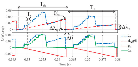
Figure 6.
Graphical illustration of the quantities in the proposed drift cancellation method.
Additionally, to minimize the noise effect, an LPF is inserted cascaded to the end of the structure. The cutoff frequency of the LPF has to be high enough to avoid filtering the signal of interest—that is, the frequency must be higher than the maximum switching frequency of the SRM. The final structure has the form presented in Figure 7, in which is the discrete time open loop LPF transfer function, is the position of the phase k, and is the filtered calculated flux linkage value.
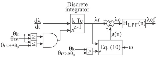
Figure 7.
Block diagram of the proposed drift cancellation method.
The proposed flux linkage calculation with drift cancellation method was implemented in MATLAB/Simulink®. The simulation results are presented in Figure 8. The figure shows the phase A electric current (IA), terminal voltage (VA), real flux linkage value (), and the phase A filtered calculated flux linkage (). The scenario used in this example is the same as the one presented in Section 3.
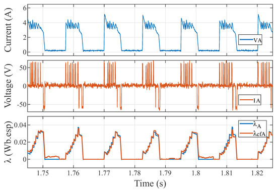
Figure 8.
Simulation results of the proposed drift cancellation method.
The waveforms of the filtered calculated flux linkage and of the real flux linkage present uncanny similarity. There are small differences in the final portion of some integration cycles, indicating that the influence of noise and offset over the calculated flux linkage changed. Nonetheless, after one integration period, the drift influence () becomes zero again, indicating that the method works properly.
Implementation Algorithm
In order to implement the proposed method, the integrator and LPF were discretized using the Tustin method [23]. After that, the inverse Z-transform was applied to find the microcontroller implementation form. The implemented integrator had the form presented in Equation (12) and the LPF had the form presented in Equation (13).
The algorithm for implementation is presented in Figure 9. In the algorithm, the flag is used to guarantee that the incremental gain is calculated only once per integration period .
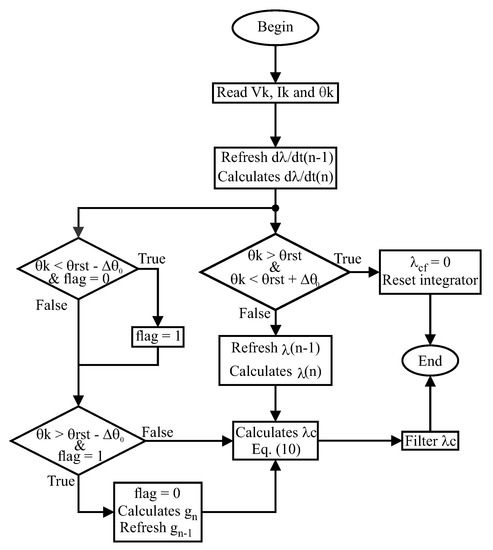
Figure 9.
Flow chart for the implementation of the proposed drift cancellation algorithm.
The algorithm is capable of calculating the flux linkage for one SRM phase. To calculate the flux linkage for more phases, the algorithm must be repeated for each phase. That assure that even if the drift effect is different among the SRM phases, the flux calculation for all phases will return an accurate value.
5. Experimental Evaluation of the Proposed Algorithm
In order to evaluate the proposed algorithm, an experimental bench was assembled. The bench and its components are presented in Figure 10 and divided in two parts. Part (a) shows a DC source set to provided constant 60 V, voltage and current sensors, a three-phase asymmetric half bridge converter, and an oscilloscope to observe the quantities of interest. The communication with the oscilloscope was established through a 12-bit parallel digital-to-analog converter (DAC). The control system was embedded in a DSP TMS320F28335 from Texas Instruments© (Dallas, TX, USA). The control frequency () was set to 20 kHz. The voltage and current sensors used were the LV20-P and LA55-P, respectively, both from LEM©. Part (b) shows the used SRM, the absolute encoder from RLS©used to acquire position, a torque transducer, and a DC machine (DCM) that could be used as load. A human–machine interface (HMI) was developed in LabView© to control the system. The used SRM had the following parameters: nominal power () kW; nominal voltage () = 30–80 V; nominal speed () rpm; nominal current () A; number of stator poles per number of rotor poles () ; phase resistance () ; maximum phase current () A; and maximum flux linkage () Wb.esp.
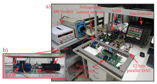
Figure 10.
Experimental setup. DAC: digital-to-analog converter; DCM: DC machine.
For better elucidation of the experimental setup, a block diagram of the mounted bench is presented in Figure 11. Note that the DCM was connected to the SRM through a torque transducer in the axle but, since it was not required for the experiment, the DCM imposed no load. The same setup is illustrated in Figure 10. The electric current and voltage from the three phases were acquired by the sensors and these quantities were used to estimate the flux linkage. The entire experiment could be controlled using the HMI.
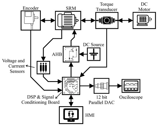
Figure 11.
Experimental setup block diagram. HMI: human–machine interface.
An open loop current hysteresis with soft-chopping control was implemented to validate the proposed method. For the experiment, the turn-on angle () was set to 25° and the turn-off angle () was set to 44°. The reference electric current was set to A. The DC source was maintained at a constant value of 60 V. The current hysteresis bands were set to A.
In order to experimentally test the proposed method, an offset error was incorporated to the calibration function in the microcontroller. A A offset was added to the phase current value and a 2 V offset was added to the phase terminal voltage value. Thus, as the DC source provided constant 60 V, the maximum apparent measured value in the voltage sensor was 62 V and the minimum was 58 V. Similarly, the current observed by the hysteresis controller was A, but the actual phase current was A.
Firstly, the experiment was realized only with the resettable integrator implemented as discussed in Section 3.1.1. The results are presented in Figure 12. The figure shows the electric current, terminal voltage, position, and calculated flux linkage for phase A. The current was controlled around the reference. The terminal voltage waveform shows that the soft-chopping was working properly. As expected, the long-term drift was mitigated by the integrator reset, but the short-term still remained, causing the baseline of the flux linkage value to increase at a constant rate until the reset occurred.
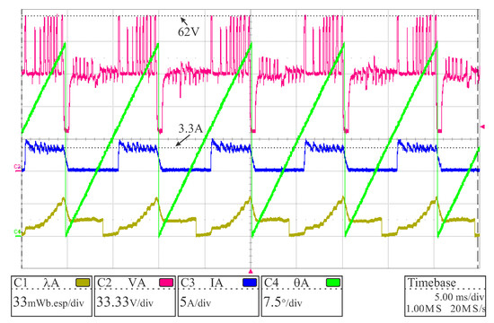
Figure 12.
Experimental results with the resettable integrator.
After that, while maintaining the same offset level in the electric current and terminal voltage values, the proposed algorithm for drift cancellation was implemented. The results are presented in Figure 13. The calculated flux linkage had the expected waveform and amplitude, with constant baseline, demonstrating that the method worked properly.
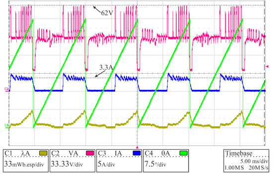
Figure 13.
Experimental results with the proposed drift cancellation method.
With the aim of further examining the performance of the proposed method, three cases are compared in Figure 14: the calculated flux of phase A from the experiment (), the calculated flux of phase A from the simulation (), and the machine flux when there was no noise and calibration offset from the simulation ().
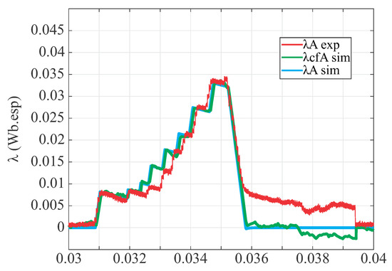
Figure 14.
Comparison between experimental and simulation results.
In order to quantify the performance of the proposed method, a statistical analysis among the waveforms presented in Figure 14 was performed. The analysis comprised the mean absolute error (MAE), the mean squared error (MSE), the R-squared factor (), the root mean square error (RMSE) and the sum of squared errors (SSE). The first comparison (named in Table 2) involved the and the . The results show that the drift problem was mitigated accordingly. The small discrepancies that appeared were generated by the white noise inserted in the simulation.
Table 2.
Goodness-of-fit statistical analysis.
The second comparison (named ) was performed between and . The results are also displayed in Table 2. As expected, this analytical comparison displayed a much larger discrepancy. The main reason for the observed difference is that the model used in the simulation disregarded the mutual inductance between the SRM phases.
Figure 15 presents the terminal voltages of phase A () and phase B (). Note that when there was a voltage variation in phase B terminals, a proportional voltage was induced in phase A, which is the main contribution of the difference between simulation and experimentally calculated flux linkage. There was also a small discrepancy between the noise present in the experiment and the noise inserted in the simulation. This difference also contributed to the small disparity in the waveforms.
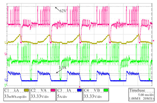
Figure 15.
Experimental results: terminal voltages of consecutive phases (phase A and phase B).
Thus, a third statistical analysis (named ) was performed, which mostly disregarded the mutual inductance effect by comparing the waveforms only in the time interval between s and s. The results are presented in Table 2. The returned values show that during the period where there was a minimal influence of the mutual inductance, the experimentally estimated flux was accurately described by the simulation, inferring that the proposed method had suitable operation.
6. Conclusions
This paper presented a new flux linkage calculation with a drift cancellation method for switched reluctance machines based on the machine’s working principles and characteristics. The method has an easy implementation algorithm and requires low computational effort. A thorough explanation was presented regarding the proposed method and other solutions in the literature. The goodness-of-fit analysis between the flux acquired from machine terminal and the estimated flux, both from the simulation, showed that the method had a good performance, reaching an of . When comparing the estimated flux from simulation and from the experiment, the was , illustrating a much lower similarity. This divergence between the simulation and experimental results comes mostly from not considering the SRM’s mutual inductance in the simulation model, but also from the difference between the experimental noise and the simulation noise that was manually inserted. Thus, a third statistical analysis considering the time interval where the mutual inductance influence was minimal showed that the experimentally estimated flux linkage was depicted by the simulation with an of . This and the other goodness-of-fit results indicate that the proposed method works properly and may be used to implement control techniques that require the flux linkage and to assess the iron losses of switched reluctance machines. Furthermore, the method could be modified and implemented in other machine topologies that have an expected zero flux linkage at some point of the electric cycle, such as synchronous reluctance machines.
Author Contributions
Conceptualization, M.V.d.P. and T.A.d.S.B.; Data curation, M.V.d.P.; Formal analysis, M.V.d.P.; Funding acquisition, T.A.d.S.B.; Investigation, M.V.d.P.; Methodology, M.V.d.P. and T.A.d.S.B.; Project administration, T.A.d.S.B.; Resources, T.A.d.S.B.; Software, M.V.d.P.; Supervision, T.A.d.S.B.; Visualization, T.A.d.S.B.; Writing—original draft, M.V.d.P.; Writing—review & editing, M.V.d.P. and T.A.d.S.B. All authors have read and agreed to the published version of the manuscript.
Funding
This research was funded by Fundação de Amparo a Pesquisa do Estado de São Paulo (FAPESP) grant number 2017/21640-9 and by Conselho Nacional de Desenvolvimento Científico e Tecnológico (CNPq).
Acknowledgments
The authors acknowledge the Department of Integrated Systems of Mechanical Engineering and the Power Electronics Lab (LEPO) of the Department of Energy Systems of Electrical Engineering, both from University of Campinas.
Conflicts of Interest
The authors declare no conflicts of interest. The funders had no role in the design of the study; in the collection, analysis, or interpretation of data; in the writing of the manuscript; or in the decision to publish the results.
Abbreviations
The following abbreviations were used in this manuscript:
| SRM | Switched reluctance machines |
| DTC | Direct torque control |
| LMS | Least mean squares |
| LPF | Low-pass filter |
| HPF | High-pass filter |
| PMSM | Permanent magnet synchronous machine |
| IPMSM | Interior permanent magnet synchronous machine |
| EKF | Extended Kalman Filter |
| DAC | Digital–analog converter |
| DCM | Direct current Motor |
| HMI | Human–machine interface |
| MAE | Mean absolute error |
| MSE | Mean squared error |
| R-squared factor | |
| RMSE | Root mean square error |
| SSE | Sum of squared errors |
References
- Barros, T.A.S.; Santos, P.J.; Paula, M.V.; Moreira, A.B.; Filho, P.S.N.; Filho, E.R. Automatic Characterization System of Switched Reluctance Machines and Nonlinear Modeling by Interpolation Using Smoothing Splines. IEEE Access 2018, 6, 26011–26021. [Google Scholar] [CrossRef]
- Zhu, Y.; Wei, W.; Yang, C.; Zhang, Y. Multi-objective optimisation design of two-phase excitation switched reluctance motor for electric vehicles. IET Electr. Power Appl. 2018, 12, 929–937. [Google Scholar] [CrossRef]
- Elmutalab, M.A.; Elrayyah, A.; Husain, T.; Sozer, Y. Extending the Speed Range of A Switched Reluctance Motor using a Fast Demagnetizing Technique. IEEE Trans. Ind. Appl. 2018, 54. [Google Scholar] [CrossRef]
- Neto, P.J.S.d.S.; Barros, T.A.; de Paula, M.V.; de Souza, R.R.; Filho, E.R. Design of Computational Experiment for Performance Optimization of a Switched Reluctance Generator in Wind Systems. IEEE Trans. Energy Convers. 2018, 33, 406–419. [Google Scholar] [CrossRef]
- Sun, Q.; Wu, J.; Gan, C.; Shen, M.; Hu, Y. Investigation of direct torque control and torque sharing function strategy for switched reluctance motor applications. In Proceedings of the 18th International Conference on Electrical Machines and Systems (ICEMS), Pattaya, Thailand, 25–28 October 2015; pp. 864–868. [Google Scholar] [CrossRef]
- Fahas, S.; LeHuy, H.; Kamwa, I. Fuzzy adaptive direct torque control of switched reluctance motors. In Proceedings of the IECON 2016—42nd Annual Conference of the IEEE Industrial Electronics Society, Florence, Italy, 23–26 October 2016; pp. 2809–2814. [Google Scholar] [CrossRef]
- Xu, A.; He, K.; Cao, Y. Torque Ripple Reduction of SRM Using Optimized Voltage Vector in DTC. In Proceedings of the IEEE Vehicle Power and Propulsion Conference (VPPC), Hangzhou, China, 17–20 October 2016; pp. 1–5. [Google Scholar] [CrossRef]
- Zhao, X.; Xu, A.; Zhang, W. Research on DTC system with variable flux for switched reluctance motor. CES Trans. Electr. Mach. Syst. 2017, 1, 199–206. [Google Scholar] [CrossRef]
- Xu, A.; Shang, C.; Chen, J.; Zhu, J.; Han, L. A New Control Method Based on DTC and MPC to Reduce Torque Ripple in SRM. IEEE Access 2019, 7, 68584–68593. [Google Scholar] [CrossRef]
- Ren, A.; Du, Z.; Li, J.; Hu, F.; Yang, X.; Abbas, H. Adaptive Interference Cancellation of ECG Signals. Sensors 2017, 17, 942. [Google Scholar] [CrossRef]
- Narasimhappa, M.; Sabat, S.L.; Nayak, J. Adaptive sampling strong tracking scaled unscented Kalman filter for denoising the fibre optic gyroscope drift signal. IET Sci. Meas. Technol. 2015, 9, 241–249. [Google Scholar] [CrossRef]
- Huang, C.; Lee, L.; Ho, C.C.; Wu, L.; Lai, Z. Real-Time RFID Indoor Positioning System Based on Kalman-Filter Drift Removal and Heron-Bilateration Location Estimation. IEEE Trans. Instrum. Meas. 2015, 64, 728–739. [Google Scholar] [CrossRef]
- Wang, Y.; Deng, Z. An Integration Algorithm for Stator Flux Estimation of a Direct-Torque-Controlled Electrical Excitation Flux-Switching Generator. IEEE Trans. Energy Convers. 2012, 27, 411–420. [Google Scholar] [CrossRef]
- Vyncke, T.J.; Boel, R.K.; Melkebeek, J.A.A. A comparison of stator flux linkage estimators for a direct torque controlled PMSM drive. In Proceedings of the 35th Annual Conference of IEEE Industrial Electronics, Porto, Portugal, 3–5 November 2009; pp. 971–978. [Google Scholar] [CrossRef]
- Shinohara, A.; Inoue, Y.; Morimoto, S.; Sanada, M. Comparison of stator flux linkage estimators for PWM-based direct torque controlled PMSM drives. In Proceedings of the IEEE 11th International Conference on Power Electronics and Drive Systems, Sydney, Australia, 9–12 June 2015; pp. 1035–1040. [Google Scholar] [CrossRef]
- Koteich, M. Flux Estimation Algorithms for Electric Drives: A Comparative Study; IEEE: Piscataway, NJ, USA, 2016; pp. 1–6. [Google Scholar] [CrossRef]
- Niu, F.; Wang, B.; Babel, A.S.; Li, K.; Strangas, E.G. Comparative Evaluation of Direct Torque Control Strategies for Permanent Magnet Synchronous Machines. IEEE Trans. Power Electron. 2016, 31, 1408–1424. [Google Scholar] [CrossRef]
- Strinić, T.; Silber, S.; Gruber, W. The Flux-Based Sensorless Field-Oriented Control of Permanent Magnet Synchronous Motors without Integrational Drift. Actuators 2018, 7, 35. [Google Scholar] [CrossRef]
- Strinić, T. A Driftless Estimation of Orthogonal Magnetic Flux Linkages in Sensorless Electrical Drives. Actuators 2018, 7, 63. [Google Scholar] [CrossRef]
- Bobtsov, A.; Pyrkin, A.; Ortega, R. A new approach for estimation of electrical parameters and flux observation of permanent magnet synchronous motors. Int. J. Adapt. Control Signal Process. 2016, 30, 1434–1448. [Google Scholar] [CrossRef]
- Kim, H.; Sul, S.; Yoo, H.; Oh, J. Distortion-Minimizing Flux Observer for IPMSM Based on Frequency-Adaptive Observers. IEEE Trans. Power Electron. 2020, 35, 2077–2087. [Google Scholar] [CrossRef]
- Woo, T.G.; Lee, S.H.; Lee, H.J.; Yoon, Y.D. Flux Weakening Control Technique without Look-Up Tables for SynRMs Based on Flux Saturation Models. Electronics 2020, 9, 218. [Google Scholar] [CrossRef]
- Nise, N.S. Digital Control Systems. In Control Systems Engineering; John Wiley & Sons: Hoboken, NJ, USA, 2004; pp. 723–780. [Google Scholar]
© 2020 by the authors. Licensee MDPI, Basel, Switzerland. This article is an open access article distributed under the terms and conditions of the Creative Commons Attribution (CC BY) license (http://creativecommons.org/licenses/by/4.0/).