Article

Unilateral Route Method to Estimate Practical Mutual Inductance for Multi-Coil WPT System

Department of Radio Communication Engineering, Korea Maritime and Ocean University (KMOU), Busan 49112, Korea
*
Author to whom correspondence should be addressed.
Electronics 2020, 9(2), 377; https://doi.org/10.3390/electronics9020377
Submission received: 20 January 2020 / Revised: 14 February 2020 / Accepted: 21 February 2020 / Published: 24 February 2020
(This article belongs to the Special Issue Wireless Power/Data Transfer, Energy Harvesting System Design)

Abstract

:
Multi-coil WPT systems require mutual inductance information between coils to increase the power transmission efficiency. However, in the high frequency (HF) bands such as 6.78 MHz and 13.56 MHz, the presence of surrounding coils changes the value of the mutual inductance between the two coils due to the parasitic element effect of the coils. These parasitic effects make it harder to estimate the mutual inductance among three or more coils. In contrast to ideal mutual inductance, which has a constant value regardless of frequency and surrounding coils, we define the practical mutual inductance as the mutual inductance varied by parasitic elements. In this paper, a new method is presented to estimate the practical mutual inductance between multiple coils in the HF band. The proposed method simply configures the expression of practical mutual inductance formula because only one of two bilateral dependent voltage sources generated by mutual inductance is considered. For several coils placed along the same axis, the practical mutual inductances between coils were measured with respect to the distance between them to validate the proposed method. The practical mutual inductance obtained from the proposed method was consistent with the simulated and measured values in HF band.

1. Introduction

Recently, multi-coil wireless power transfer (WPT) systems using three or more coils have been proposed to achieve a high power transfer efficiency (PTE) at greater distance than in the case of a conventional two-coil WPT system [1,2,3,4,5,6,7,8,9,10,11,12]. The multi-coil WPT systems are categorized into the domino structure and multiple transmitting (or receiving) coils structure. The domino structure means that one or more coils are placed between transmitting and receiving coils [1,2,3,4,5,6]. To achieve a long transmission distance, the structure adjusts the capacitance of each coil or gaps among coils. On the other hand, multiple transmitting (or receiving) coils correspond to the multiple input single output (MISO) or single input multiple output (SIMO) system in the wireless communication field [7,8,9,10,11,12]. The WPT system with multiple transmitting coils usually maximizes the power in the receiving coil through entering power of different magnitude or phase into transmitting coils. Sometimes, this technique is called magnetic beamforming [7,8].
The trouble in implementing these multi-coil WPT systems is that the mutual inductances (or coupling coefficients) among coils should be basically known. For the domino structure, the coupling coefficient information is used to estimate the target free-resonant frequencies, that is the resonant capacitances, or target distances between adjacent coils. For the multiple transmitting coils, power can be transferred into a not-aligned receiving coil by controlling the phase and magnitude of signal components input to each transmitting coil, where the mutual inductance information is used to calculate the phase and magnitude of input power [7,8]. This technique is referred to as magnetic beamforming. Similarly, for the multiple receiving coils, the output power can be maximized by adjusting the phase of the received power based on the mutual inductance information. Therefore, the accurate value of mutual inductance between coils is important to obtain high efficiency of multi-coil WPT systems such as domino, MISO, and SIMO structures in common. On the other hand, inaccurate mutual inductance causes interruption of maximum performance for the multi-coil systems.
The ideal mutual inductance between coils is completely separated from the operating frequency or presence of surrounding coils. In practice, when the mutual inductance between coils is measured, the measurement frequency and the presence of surrounding coils affect the measurement results. These phenomena can be inferred by the effect of the parasitic elements of the coil. We refer to the mutual inductance affected by the parasitic elements as the practical mutual inductance.
As is well known, the parasitic effect of a component is commonly frequency dependent, which becomes large as the frequency increases [13]. That is, the parasitic effects are not significant and can be ignored in low frequency (LF) bands such as 100–205 kHz. Therefore, most previous researches on the mutual inductance for the WPT system have focused on the estimation of the ideal mutual inductance of two coils with respect to the alignment status [14,15,16,17,18]. For WPT systems used in the HF band such as 6.78 MHz and 13.56 MHz, the practical mutual inductances between the transmitting and receiving coils are different from the theoretical value due to the effect of the parasitic component. S. Hackl et al. proposed an equivalent circuit model for the radio frequency identification (RFID) system with two coils operating at a very close distance considering not only the parasitic capacitors but also the capacitive coupling between coils [19]. However, the capacitive coupling between coils is generally taken account for 1 cm or less gap between coils, while the WPT system in the HF band is mainly used for a distance of tens or several cm. In addition, the method is difficult to expand to three or more coils because of complicated formulation.
In HF band, the practical mutual inductance between two coils can be easily measured using a vector network analyzer (VNA). However, it cannot be used to measure the practical mutual inductance among three or more coils since public VNAs usually have only two ports. Moreover, it is obvious that the number of transmitting or receiving coils tends to increase steadily. As the number of coils increases, the parasitic effect becomes greater. Therefore, an effective method is highly required to estimate the practical mutual inductance among multiple coils with parasitic effects using a two-port VNA in HF band. In this paper, a new method is proposed to obtain the practical mutual inductance among multiple coils using a general two-port VNA under the assumption that the coils are unilateral instead of reciprocal characteristics. The proposed method is suitable for general HF band WPT systems used at several cm distance and the simple expression of the formula allows to determine the effect of the presence of surrounding coils through every possible route among coils. We also verify the proposed method by comparison with measured and simulated mutual inductance among multiple coils.

2. Theoretical Analysis

This section presents theoretical analysis for the proposed unilateral route method.

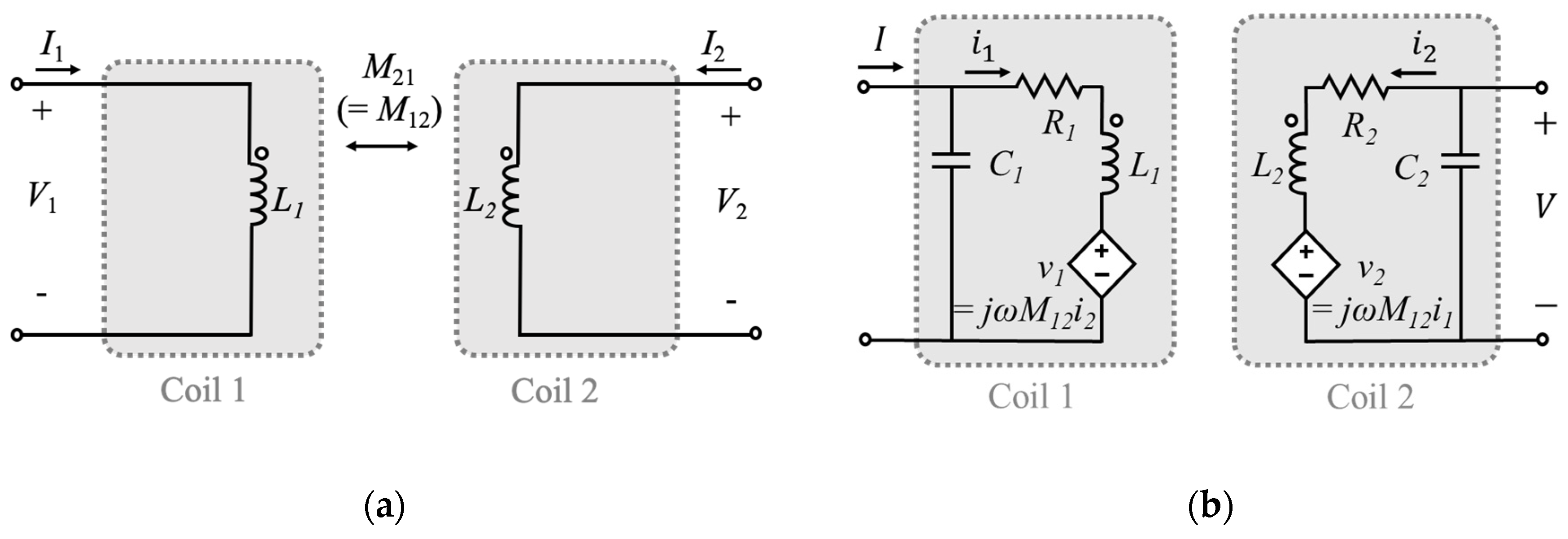
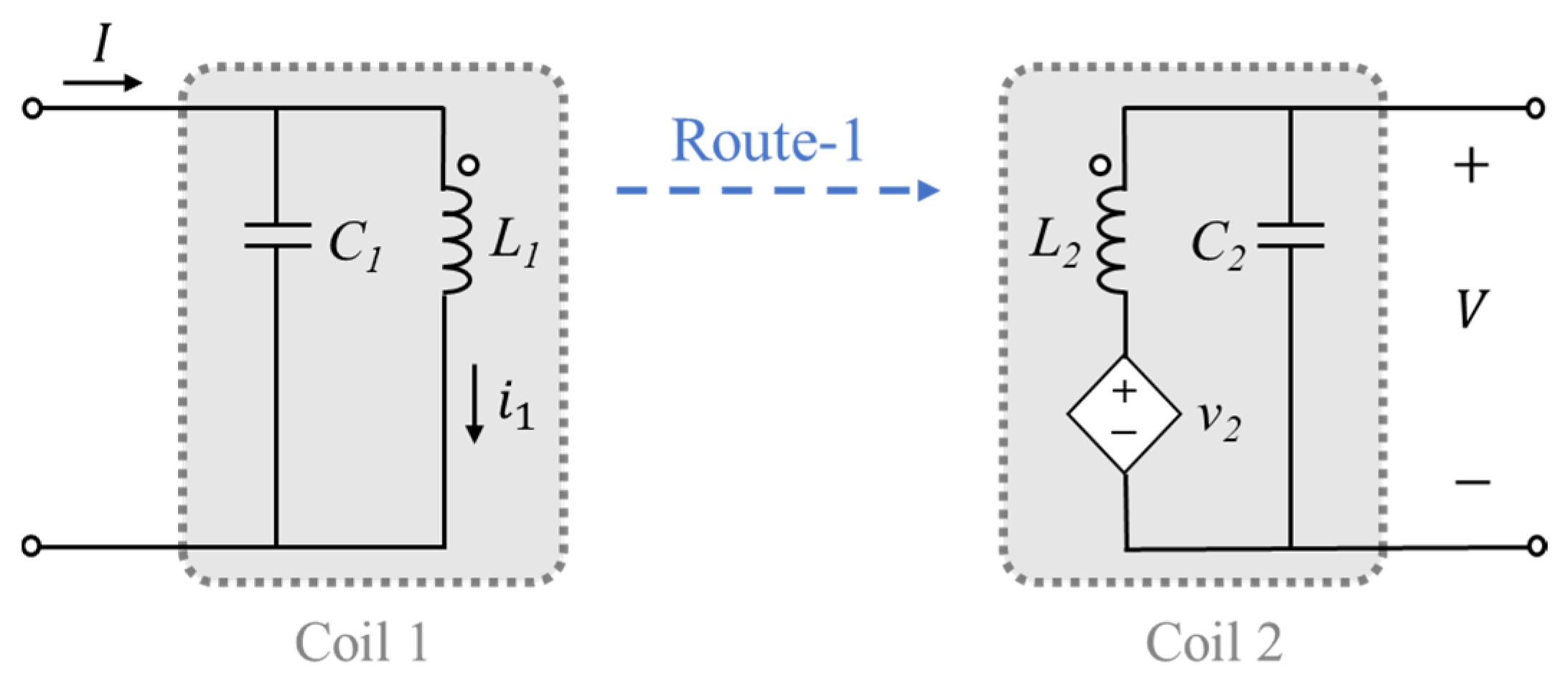
2.1. Practical and Ideal Mutual Inductance between Two Coils

Figure 1a,b shows the equivalent circuit model of two ideal coils and two coils with parasitic element, respectively. If the two coils are considered as a two-port network, the two-port network can be represented by various two-port parameters such as impedance parameter and scattering parameter. For the two ideal coils of Figure 1a, the mutual inductance between the two coils is independent of the operating frequency. From the definition of the impedance parameter, the transfer impedance between two ideal coils is given by
Z 21 = V 2 I 1 | I 2 = 0 = j ω M 21 ,
where Vi and Ii are the voltage and current of the ith port, and ω is the angular frequency. M21 is the mutual inductance between the coils and the two-port network is reciprocal so that Zij = Zji and Mij = Mji. Equation (1) means that Zij can be found by exciting port j with the current Ij, open-circuiting all other ports, and measuring the open-circuit voltage at port i. From Equation (1), the mutual inductance (M21) between the coils can be easily obtained by measuring the transfer impedance (Z21). This method is commonly used to measure the mutual inductance between the coils.
On the other hand, as the operating frequency increases, the coil is not presented as a single inductor but combined with parasitic elements such as resistor and capacitor. However, the parasitic capacitor is only considered as shown in the equivalent model of Figure 1b. This is because the parasitic resistor of coils is usually much smaller than the impedance (ωL) of the inductor in HF band, R << ωL1, and then the reactance is dominant in determining the current flowing on the inductor and series parasitic resistor. Moreover, the parasitic capacitor of real coil connected in parallel makes a closed-loop, which causes the current path. Therefore, while the real coil is open-terminated in HF band, the practical mutual inductance between two coils is changed by the current path. From the circuit theory, the transfer impedance between the two coils with parasitic capacitors is given by
Z 21 = V 2 I 1 | I 2 = 0 = i 1 I 1 v 2 i 1 V 2 v 2 | I 2 = 0 = 1 j ω C 1 1 j ω C 1 + j ω L 1 + ( ω 2 M 12 2 1 j ω C 2 + j ω L 2 ) j ω M 21 1 j ω C 2 1 j ω C 2 + j ω L 2
The transfer impedance Z21 is presented by multiplying the ideal transfer impedance jωM and other terms. From Equation (2), causes of the parasitic effect are categorized into two. First, not all of the input current (I1) of port 1 flows through L1 due to the presence of C1 and only part (i1) of the current flows; then, the induced voltage (v2) on L2 decreases. In addition, the induced voltage (v2) generates the current (i2) flowing closed current path, which consists of L2 and C2, even when port 2 is opened. Then, the current (i2) flowing through L2 induces the voltage (v1) on L1 by the mutual inductance. Consequently, this lowers the amount of the current (i1) flowing through L1 and also lowers the induced voltage (v2). This effect is expressed as the first term of the right side of Equation (2). Second, the voltage (v2) induced in Coil 2 is divided into L2 and C2 so that only a part of the induced voltage (V2) is delivered into port 2. This voltage distribution is expressed by the third term on the right side of Equation (2).
Similar to Equation (1), we define the transfer impedance using the practical mutual inductance (M21(practical)) as
Z 21 = j ω M 21 ( practical ) .
Comparing Equation (3) with Equation (2) yields that M21(practical) is obviously different with M12 and strongly dependent on the coils’ inductance, L1 and L2, and the parasitic capacitance, C1 and C2, as well as the angular frequency, ω.
The term in parentheses in the first term denominator of Equation (2) means that some of the voltage induced from Coil 1 to Coil 2 is induced again to Coil 1 through mutual inductance. Except for special cases where the coils are very close to each other or operate near the self-resonant frequency (SRF) of the coils, it is small enough to be negligible compared to other terms. Therefore, Equation (2) can be approximately expressed as follows in combination with Equation (3)
M 21 ( practical ) = Z 21 j ω 1 j ω C 1 j ω L 1 + 1 j ω C 1 M 21 1 j ω C 2 j ω L 2 + 1 j ω C 2 .
Equation (4) is equivalent to the circuit diagram of Figure 2 that shows the dependent voltage source on L1 removed in Figure 1b. That is, it is assumed that the coils are unilateral. If the coils’ parameters, L1, C1, L2 and C2, are known, the ideal mutual inductance M21 can be obtained by measuring the transfer impedance Z21 and using Equation (4). Conversely, if the coil’s parameters and ideal mutual inductance M21 are known, the practical mutual inductance M21(practical) in the HF band can be estimated by using Equation (4).

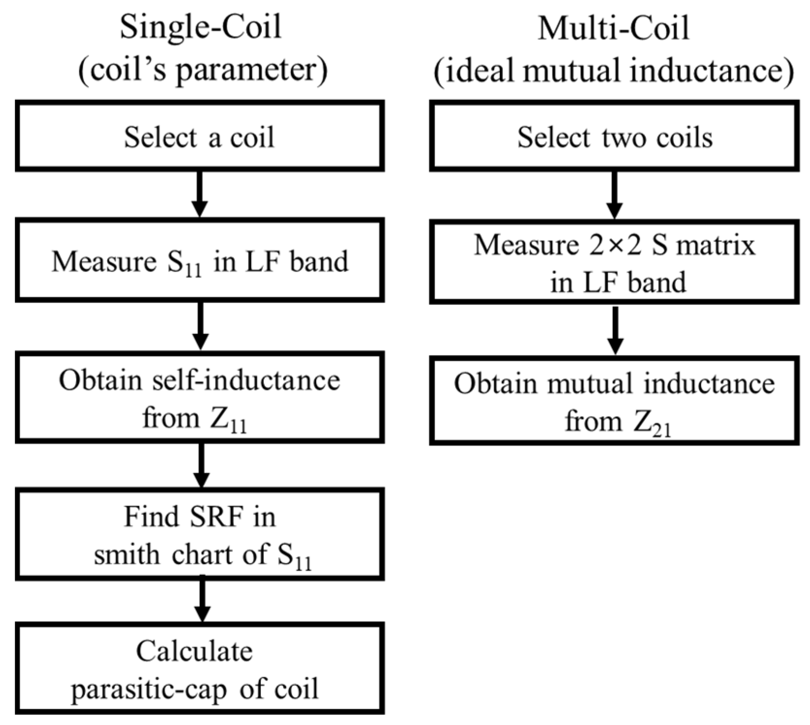
2.2. Measurement Method for the Coil’s Parameters and Ideal Mutual Inductance between Two Coils

As mentioned above, the coil’s parameters and ideal mutual inductance should be known in order to estimate the practical mutual inductance between two coils. Figure 3 shows the proposed procedure to obtain the coil’s parameters and ideal mutual inductance. First, parameters of each single coil are measured without surrounding coils or the object. Since the parasitic effect rarely appears in the LF band, the input impedance Z11 of a single coil is simply expressed as R1 + jωL1. Therefore, the self-inductance and resistance of each coil are directly obtained by measuring the input impedance of the coil using a VNA at the lowest possible frequency in the LF band. Next, the parasitic capacitance C1 of the coil can be obtained from the SRF of the coil as given by
C 1 = 1 ω 0 2 L 1 = 1 ( 2 π f 0 ) 2 L 1 ,
where f0 is the SRF at which the reactance of the coil is zero, and it can be easily measured from the Smith Chart of S11 or the input impedance plot on the VNA. Finally, the ideal mutual inductance M21 between two coils can also be obtained from measuring the transfer impedance Z21 between the coils using the VNA in the LF band. Therefore, the parameters of coils measured through the procedure of Figure 3 can be used to estimate the practical mutual inductance between two coils. Moreover, if the ideal mutual inductances among three or more coils are well defined, the measured parameters can also be used to estimate the practical mutual inductance.

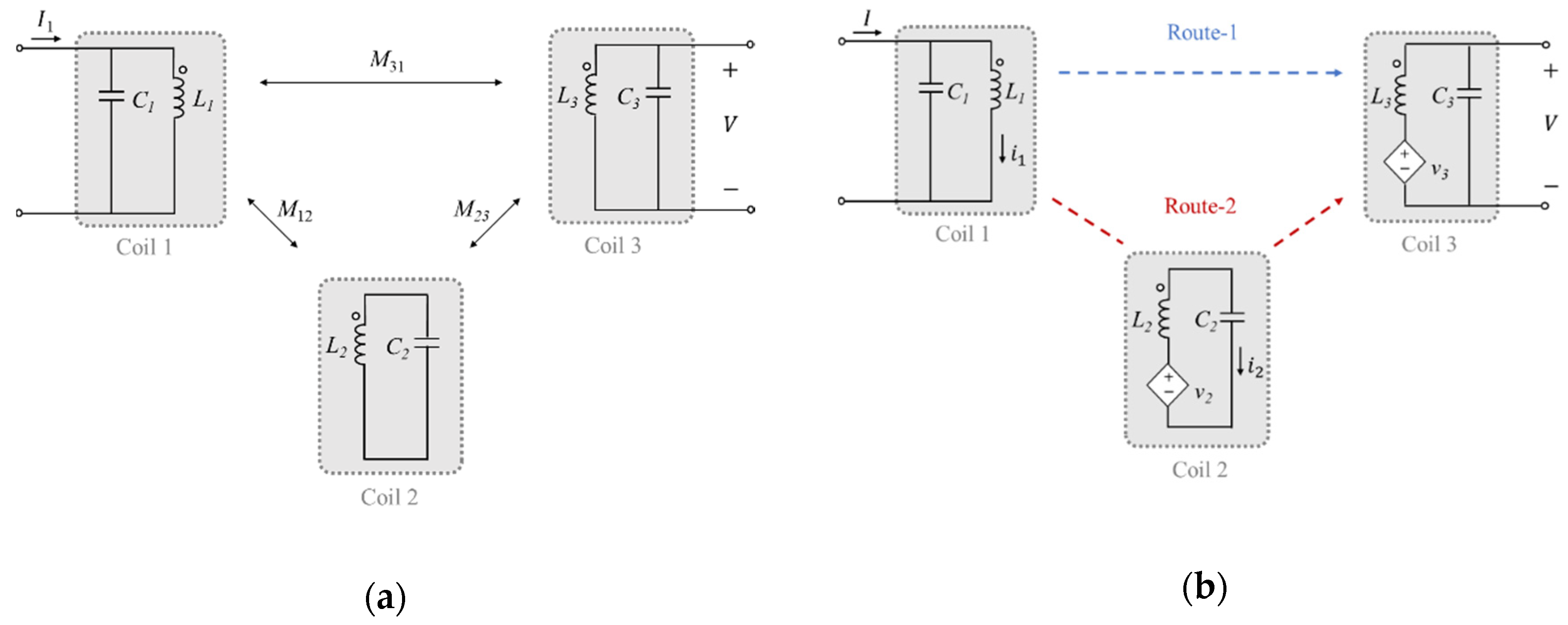
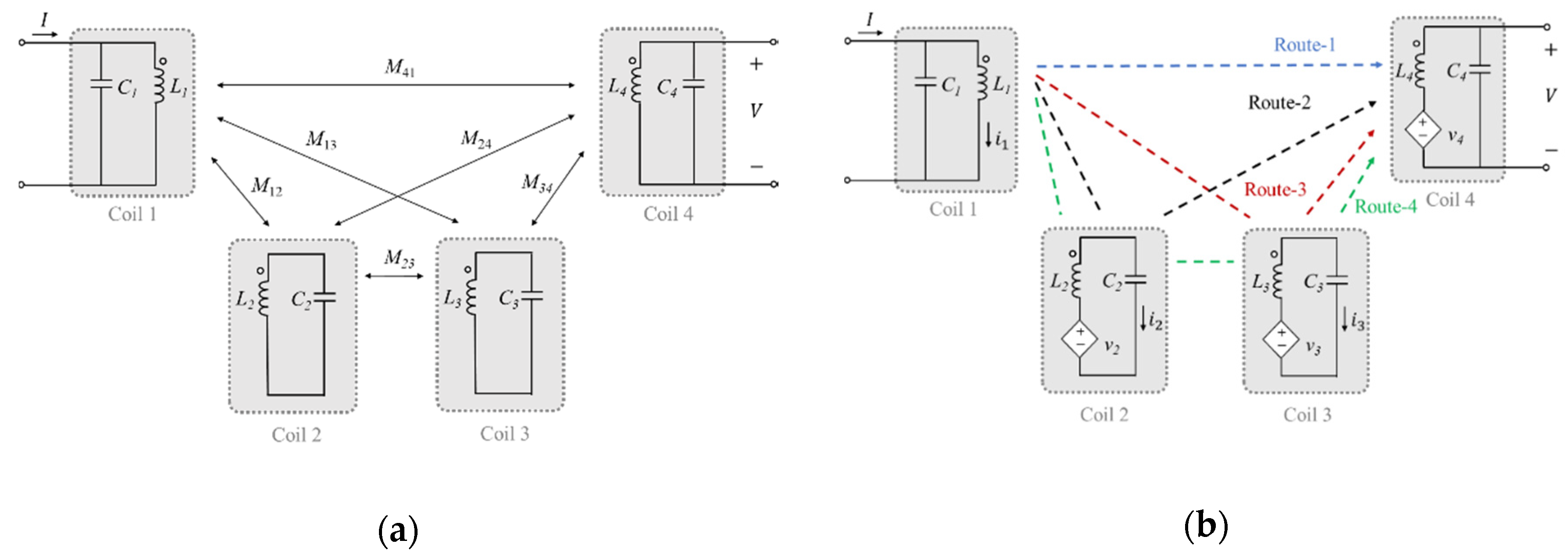
2.3. Transfer Impedance of Multi-Coil Using the Proposed Circuit Model

For three coils shown in Figure 4a, we should estimate the transfer impedance Z31 between Coils 1 and 3 to obtain the practical mutual inductance between the coils. From the definition of impedance parameter, the current applied to the first port can directly induce the voltage on the opened third port and also indirectly induce the voltage via the second port. Strictly, the induced voltage makes a current in the closed loop formed by the parasitic capacitor, and the current in the third inductor can affect other inductors. However, since the high order mutual effects are weak, under the assumption that the coils are unilateral, the transfer impedance between Coils 1 and 3 is obtained as the sum of two routes in Figure 4b. Thus, the practical mutual inductance between Coils 1 and 3 is given by
M 31 ( practical ) = Z 31 j ω Z R 1 + Z R 2 j ω ,
where ZR−1 and ZR−2 are the transfer impedances of the direct and one-hop indirect routes between Coils 1 and 3, respectively, as shown in Figure 4b. Using Equation (4) the transfer impedance of the direct route is given by
Z R 1 = 1 j ω C 1 j ω L 1 + 1 j ω C 1 j ω M 31 1 j ω C 3 j ω L 3 + 1 j ω C 3 .
From unilateral characteristics, the transfer impedance of the indirect one-hop route is also easily obtained by
Z R 2 = V I = i 1 I j ω M 21 1 Z 2 j ω M 32 V v 3 = 1 j ω C 1 j ω L 1 + 1 j ω C 1 j ω M 21 1 j ω L 2 + 1 j ω C 2 j ω M 32 1 j ω C 3 j ω L 3 + 1 j ω C 3 ,
where M21, M32 and M31 are ideal mutual inductances, and the minus sign is due to the dot notation between Coils 1 and 2.
For four coils shown in Figure 5, there are four possible routes from Coil 1 to Coil 4 under the unilateral assumption. The transfer impedance of the fourth route is given by
Z R 4 = V I = i 1 I j ω M 21 1 Z 2 j ω M 32 1 Z 3 j ω M 43 V v 4 .
The practical mutual inductance is summarized as
M 41 ( practical ) = Z 41 j ω Z R 1 + Z R 2 + Z R 3 + Z R 4 j ω .
If the number of coils is n, the transfer impedance is determined as
Z n 1 k = 1 2 n 2 Z R k .

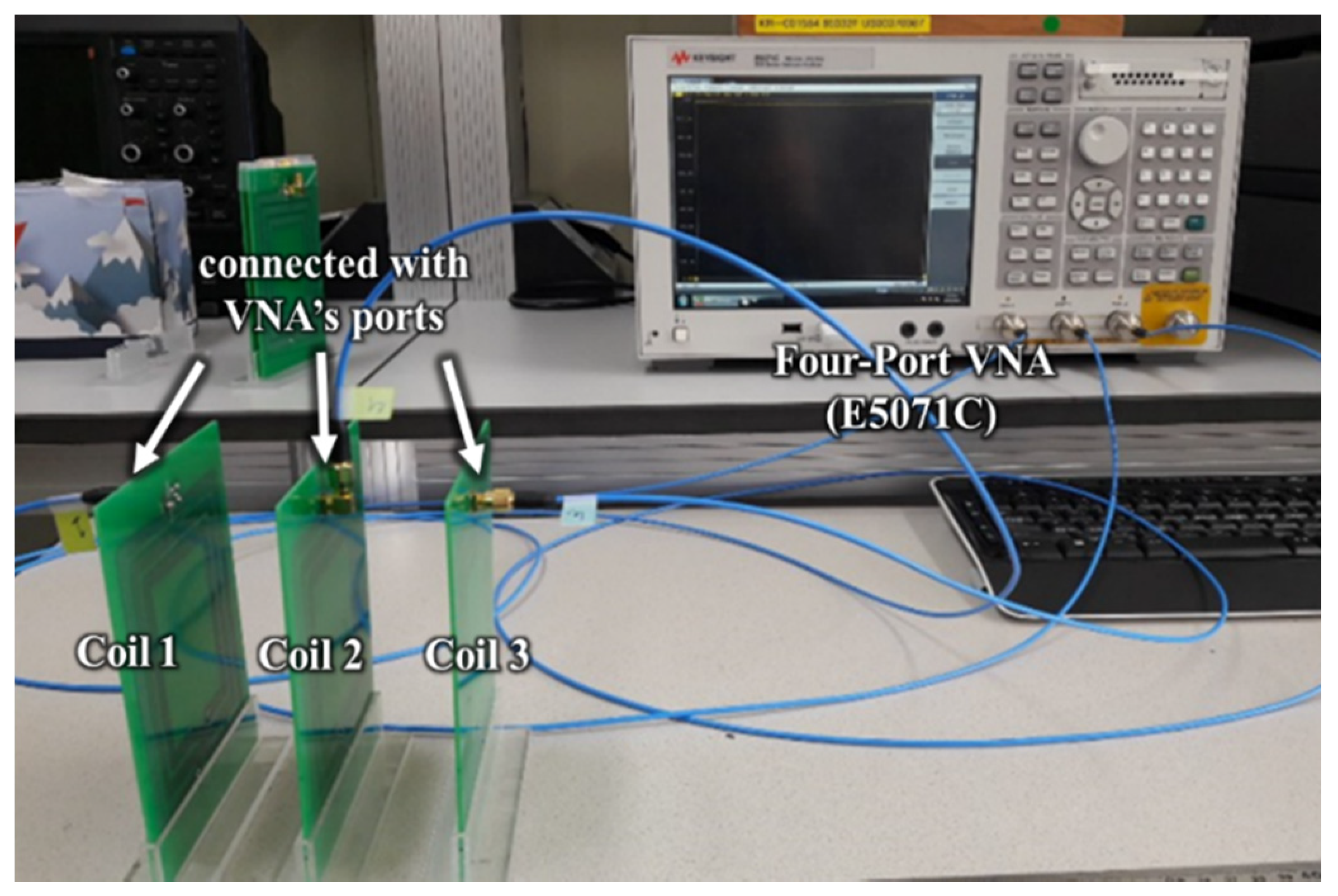
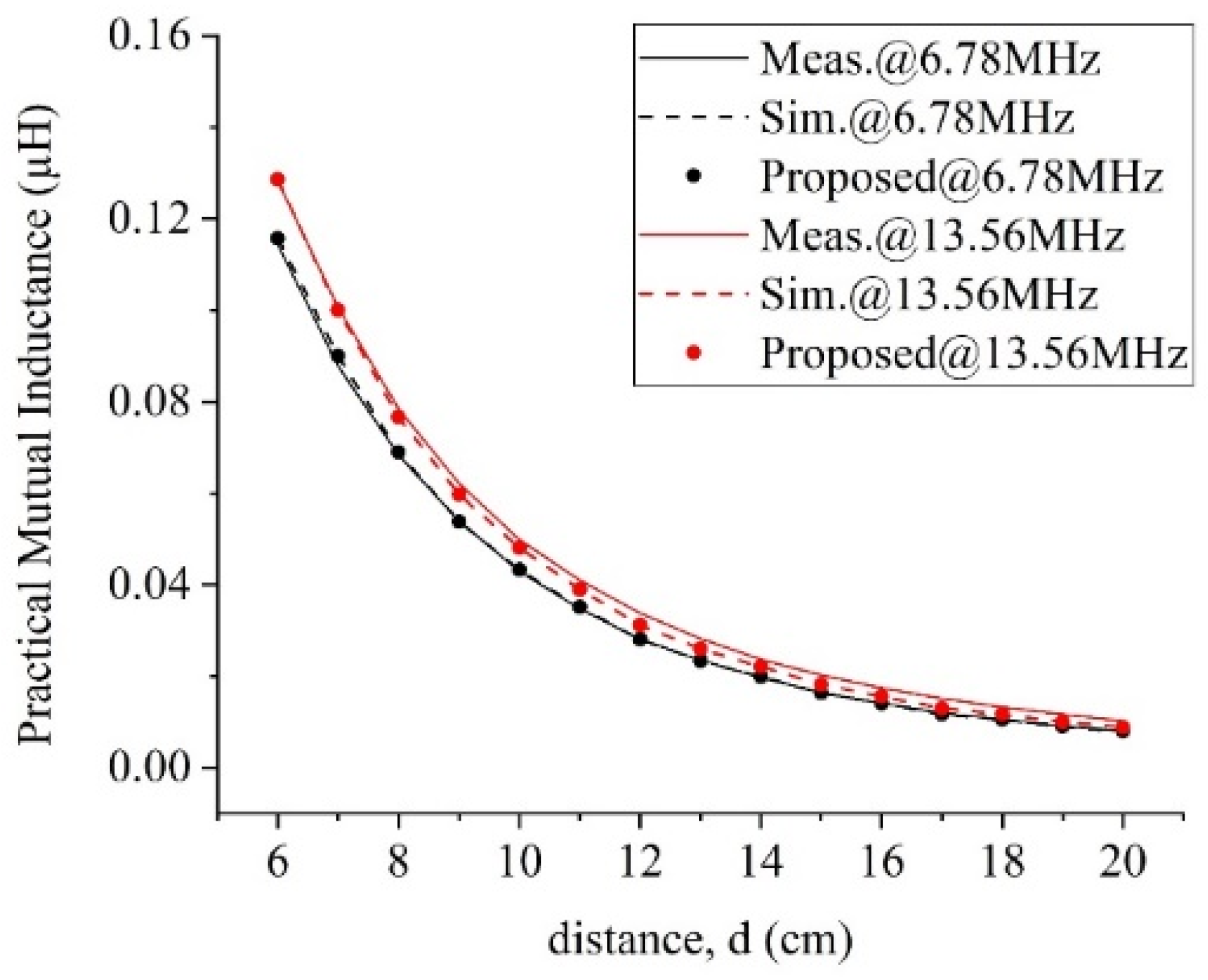
3. Experimental Results and Discussion

To verify the proposed method in the HF band, we analyzed the practical mutual inductance by changing the number of coils as shown in Figure 6. Two types of coils were used for the experiment, and parameters of the coils are summarized in Table 1. Coila has three turns and a single layer printed on an FR-4 substrate and dimensions 95.7 mm × 105.7 mm. Coilb has six turns and two layers printed on an FR-4 substrate of the same dimensions as the Coila. All coils were arranged coaxially in order to maximize the parasitic effect and the effect of surrounding coils. The practical mutual inductance among multiple coils was measured with respect to the distance using the four-port VNA, Agilent’s E5071, as shown in Figure 7. Therefore, the [S] matrix for three coils that are directly connected to ports of the multi-port VNA was measured and then converted into the [Z] matrix using the equation in [20] on the Keysight’s ADS.
Additionally, we simulated the practical mutual inductance from the full circuit models with all parasitic components and dependent voltage sources using the ADS, and the measured practical mutual inductances are compared with the simulated results as well as those from the proposed method in several cases.

3.1. Two Coils Analysis

For two coils of Figure 6a, where the two coils used are identical to Coila in Table 1, the S parameters were measured without surrounding coils and the practical mutual inductances were estimated by substituting the Z parameters converted from S parameters into Equation (4). Figure 8 shows the measured and simulated practical mutual inductances with those of the proposed estimation method. As the distance between the coils decrease, the ideal mutual inductance increases and then the practical mutual inductance also increases. On the other hand, at 13.56 MHz, the practical mutual inductance has a higher level than 6.78 MHz. This result comes from the first and third terms of the right-hand side of Equation (4), being a function of frequency. As the frequency increases, the magnitude of the denominators of the terms dramatically increases more than those of the numerators. The mutual inductances estimated by the proposed method are in good agreement with the simulated and measured values over the distance. The closer the distance between the coils and the higher the frequency, the larger the practical mutual inductance becomes due to the parasitic effect. The proposed method accurately simulates these effects.

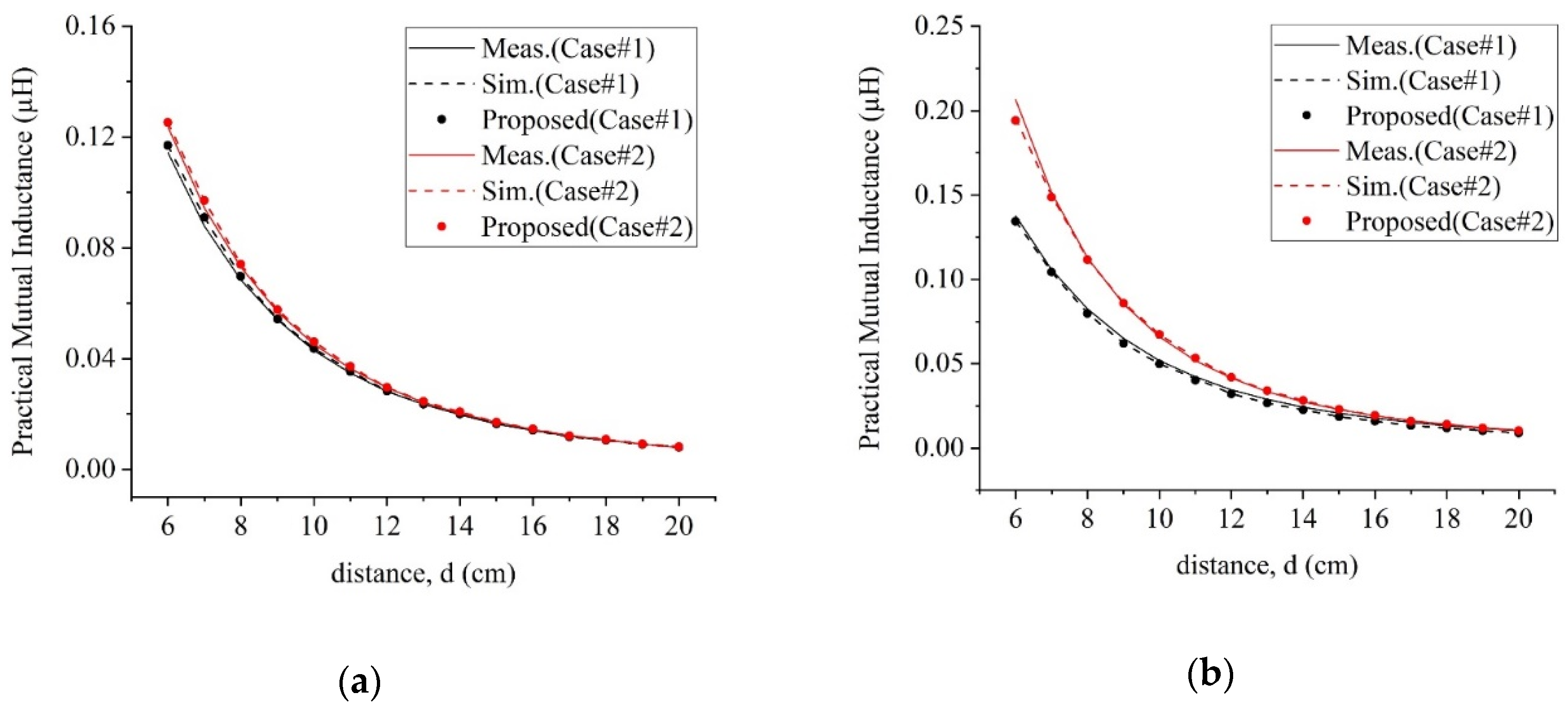
3.2. Three Coils Analysis

For three coils of Figure 6b, the experiments were conducted on the two cases of Table 2, where Coil 2 was located in the middle of Coils 1 and 3. The self-inductance of Coil 2 for Case#2 is larger than the value for Case#1. Figure 9 shows the simulated, measured, and estimated practical mutual inductances with respect to distance at 6.78 MHz and 13.56 MHz. It is noticed that the variation in the mutual inductance with Case#2 is greater than Case#1. This means that the larger the inductance of the surrounding coils, the greater the influence on the mutual inductance between other coils. In addition, the variation of the practical mutual inductance is greater at 13.56 MHz than at 6.78 MHz. That is, the parasitic effect is larger at a higher frequency. On the other hand, the proposed method exactly estimates the practical mutual inductance all over the distance, even if the parameters of the coil change.
To show the accuracy of the proposed method, we calculate the mean and normalized root-mean-square error (NRMSE) of difference between the results of measurement and the proposed method shown in Figure 8 and Figure 9, and summarize them in Table 3. While the mean and NRMSE increase as the number of coil and frequency increases, the mean and error are less than 20×10−10 (0.002 μH) and 3%, respectively, for all cases. This means that the proposed method accurately estimates the practical mutual inductance as measured by a multi-port VNA.

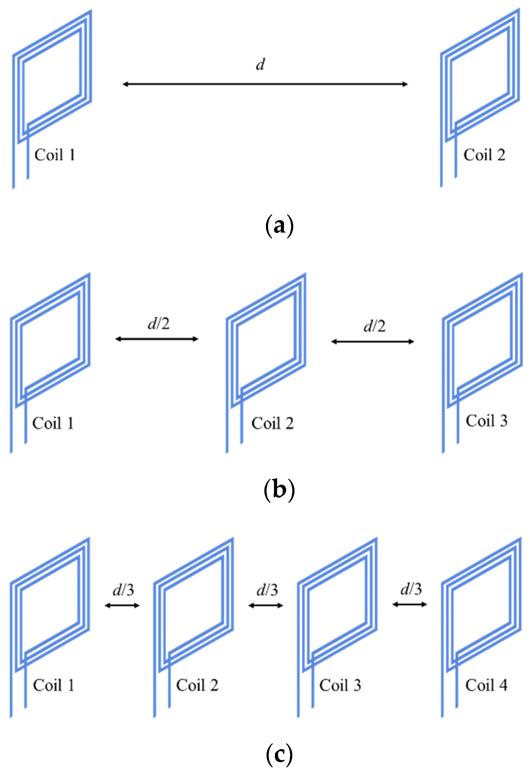
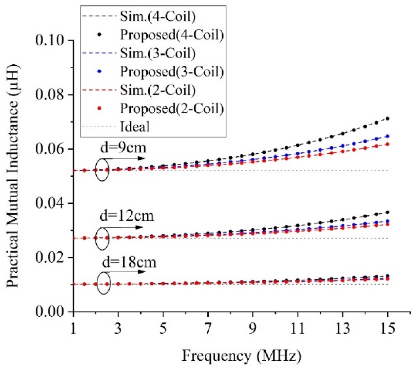
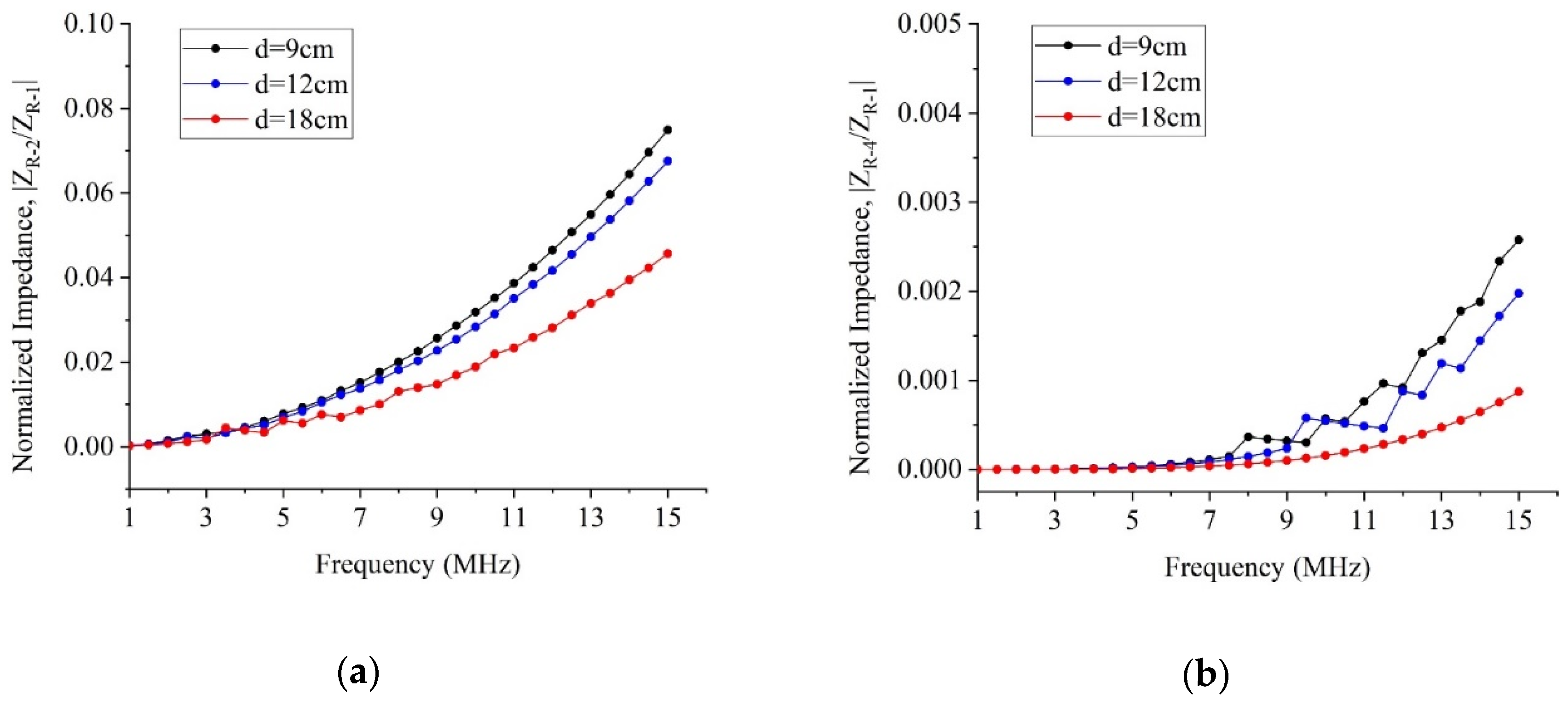
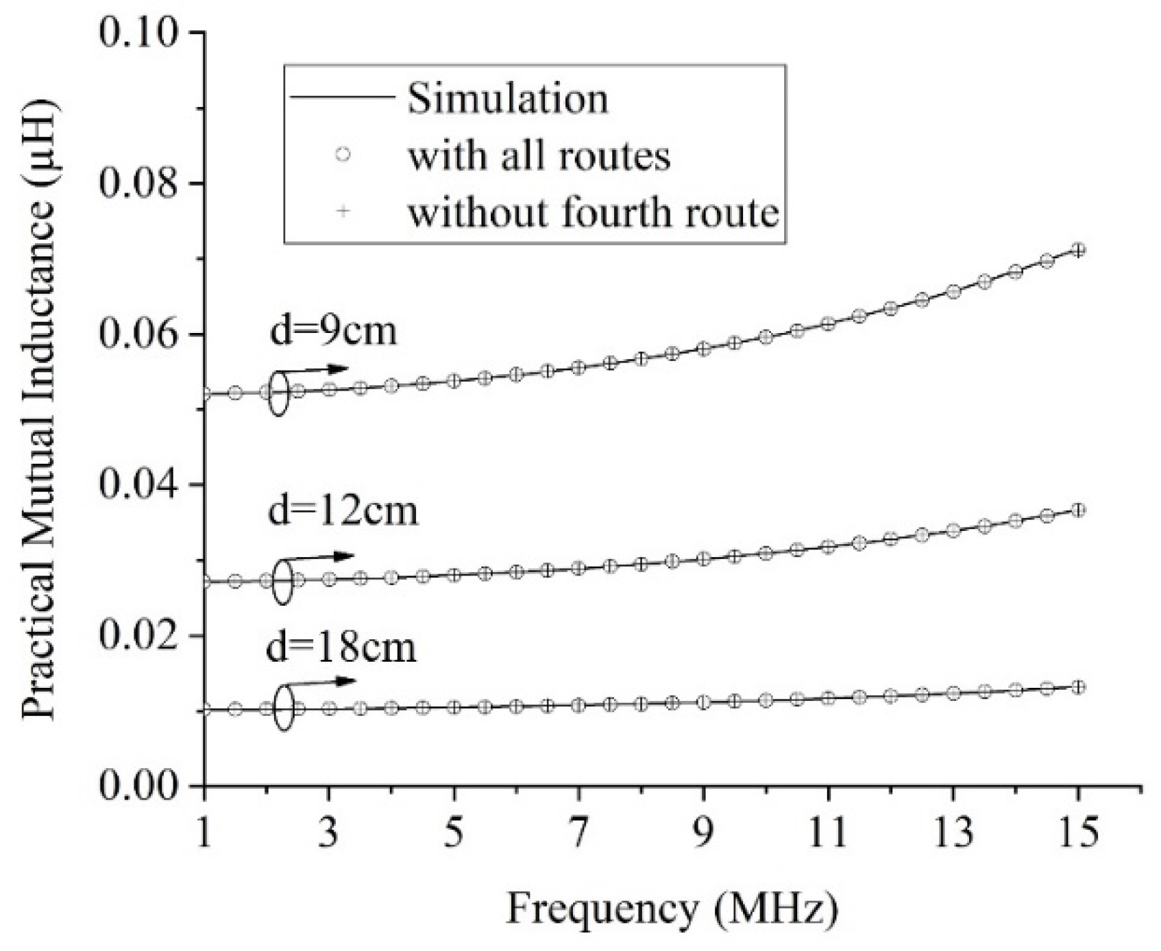
3.3. Analysis of Unilateral Method for the Number of Coils

Figure 10 shows the practical mutual inductance as a function of the frequency at several distances for two, three, and four coils as shown in Figure 6. The parameters of all arranged coils are identical with Coila in Table 1. The ideal mutual inductance does not depend on the frequency, but the practical mutual inductances are proportional to frequency. In addition, as the number of coils increases, the mutual inductance increases further due to the parasitic effect. In these cases, the results of the proposed method are almost identical to the simulated value.
Figure 11 shows the simulated transfer impedance of each route for four coils, which is normalized by the transfer impedance of the direct route, ZR−1. The transfer impedances of one- and two-hop indirect routes are presented in Figure 11a,b, respectively. As the number of hops increase, the transfer impedance decreases dramatically. In other words, the normalized transfer impedance of one-hop routes have a value smaller than 0.1, while those of two-hop routes have a very small value of less than 0.005. Thus, the two-hop route is almost unaffected as an element to obtain the practical mutual inductance in a four-coil array. This means that among 2 n 2 routes for n coils, only the direct and one-hop routes are practically dominant, so the transfer impedance between the primary and the nth coil can be approximately expressed as
Z n 1 k = 1 2 n 2 Z R k k = 1 n 1 Z R k .
Finally, for four coils, the practical mutual inductances by all routes and the routes except two more hopping routes with respect to the frequency are as shown in Figure 12. Even if the two-hop routes are not taken into account, the calculated mutual inductances are in good agreement with the results of all the routes as well as the simulated results.

4. Conclusions

The multi-coil WPT systems commonly use three or more coils to improve efficiency in HF bands as well as LF bands. These systems are basically required to estimate or measure the practical mutual inductance between coils. In this paper, the unilateral approach method is proposed to estimate the mutual inductance among multiple coils. With the proposed method, it is not only simple to configure the expression of formulas but also possible to estimate the practical mutual inductance through several routes for multiple coils since the assumption that only one voltage generated with respect to the coil pair was considered. To verify the validity of the proposed method, we coaxially placed several coils along the distance and confirmed the consistent results with simulation and measurement. In reality, it is difficult to analyze the mutual inductance in multiple coils using a public VNA that has only two ports. However, the proposed method can provide the mutual inductance using a public two-port VNA. Furthermore, it will be quite useful for the multi-coil WPT systems with a regular array of identical coils.

Author Contributions

Conceptualization, S.-J.J. and S.-H.L.; methodology, S.-J.J.; software, S.-J.J.; validation, S.-J.J. and S.-H.L.; formal analysis, S.-J.J. and D.-W.S.; investigation, S.-J.J. and S.-H.L.; resources, S.-H.L.; data curation, S.-J.J.; writing—original draft preparation, S.-J.J.; writing—review and editing, D.-W.S.; visualization, S.-J.J.; supervision, D.-W.S.; project administration, D.-W.S.; funding acquisition, D.-W.S. All authors have read and agreed to the published version of the manuscript.

Funding

This work was supported by the National Research Foundation of Korea (NRF) grant funded by the Korea government (MSIT) (No. 2018R1C1B6003854).

Conflicts of Interest

The authors declare no conflicts of interest.

References

  1. Zhong, W.X.; Lee, C.K.; Hui, S.Y.R. General analysis on the use of tesla’s resonators in domino forms for wireless power transfer. IEEE Trans. Ind. Electron. 2013, 60, 261–270. [Google Scholar] [CrossRef] [Green Version]
  2. Kim, J.H.; Park, B.C.; Lee, J.H. Optimum design of WPT relay system by controlling capacitance. Microw. Opt. Technol. Lett. 2014, 56, 1658–1661. [Google Scholar] [CrossRef]
  3. Sun, Y.; Liao, Z.J.; Ye, Z.H.; Tang, C.S.; Wang, P.Y. Determining the maximum power transfer points for MC-WPT systems with arbitrary number of coils. IEEE Trans Power Electron. 2018, 33, 9734–9743. [Google Scholar] [CrossRef]
  4. Seo, D.W. Design method of three-coil WPT system based on critical coupling condition. IEEE J. Emerg. Sel. Top. Power Electron. 2019. [Google Scholar] [CrossRef]
  5. Sun, T.; Xie, X.; Li, G.; Gu, Y.; Wang, Z. Indoor wireless power transfer using asymmetric directly-strong-coupling mechanism. Microw. Opt. Technol. Lett. 2013, 55, 250–253. [Google Scholar] [CrossRef]
  6. Xu, B.; Li, Y. Investigation of surface wave propagation along a multi-coil wireless power transfer system. Microw. Opt. Technol. Lett. 2016, 58, 2261–2265. [Google Scholar] [CrossRef]
  7. Jadidian, J.; Katabi, D. Magnetic MIMO: How to charge your phone in your pocket. In Proceedings of the 20th Annual International Conference on Mobile Computing and Networking (MOBICOM), Maui, HI, USA, 7–11 September 2014; pp. 495–506. [Google Scholar]
  8. Shi, L.; Kabelac, Z.; Katabi, D.; Perreault, D. Wireless power hotspot that charges all of your devices. In Proceedings of the 21th Annual International Conference on Mobile Computing and Networking (MOBICOM), Paris, France, 7–11 September 2015; pp. 2–13. [Google Scholar]
  9. Sritongon, C.; Wisestherrakul, P.; Hansupho, N.; Nutwong, S.; Sangswang, A.; Naetiladdanon, S.; Mujjalinvimut, E. Novel IPT multi-transmitter coils with increase misalignment tolerance and system Efficiency. In Proceedings of the 2018 IEEE International Symposium on Circuits and Systems (ISCAS), Florence, Italy, 27–30 May 2018; pp. 1–5. [Google Scholar]
  10. Nguyen, M.Q.; Ta, K.; Dubey, S.; Chiao, J.C. Frequency modes in a MIMO wireless power transfer system. In Proceedings of the 2017 IEEE Asia Pacific Microwave Conference (APMC), Kuala Lumpar, Malaysia, 13–16 November 2017; pp. 146–149. [Google Scholar]
  11. Kim, D.H.; Ahn, D. Maximum efficiency point tracking for multiple-transmitters wireless power transfer. IEEE Trans. Power Electron. 2019. [Google Scholar] [CrossRef]
  12. Fu, M.; Zhang, T.; Ma, C.; Zhu, X. Efficiency and optimal loads analysis for multiple-receiver wireless power transfer systems. IEEE Trans. Microw. Theory Tech. 2015, 63, 801–812. [Google Scholar] [CrossRef]
  13. Alley, C.L.; Atwood, K.W. Electronic Engineering; Wiley: Hoboken, NJ, USA, 1973; p. 199. [Google Scholar]
  14. Piri, M.; Jaros, V.; Fricaldsky, M. Verification of a mutual inductance calculation between two helical coils. In Proceedings of the 2015 16th International Scientific Conference on Electric Power Engineering (EPE), Kouty nad Desnou, Czech Republic, 20–22 May 2015; pp. 712–717. [Google Scholar]
  15. Wu, L.; Lu, K.; Xia, Y. Mutual inductance calculation of two coaxial solenoid coils with iron core. In Proceedings of the 2018 21st International Conference on Electrical Machines and System (ICEMS), Jeju, Korea, 7–10 October 2018; pp. 1804–1808. [Google Scholar]
  16. Ariffin, A.; Inamori, M. Influence of mutual inductance measurement for high efficiency wireless power transmission. In Proceedings of the 2018 7th International Conference on Renewable Energy Research and Applications (ICRERA), Paris, France, 14–17 October 2018; pp. 949–953. [Google Scholar]
  17. Zhang, X.; Meng, H.; Wei, B.; Wang, S.; Yang, Q. Mutual inductance calculation for coils with misalignment in wireless power transfer. IET J. Eng. 2019, 16, 1041–1044. [Google Scholar] [CrossRef]
  18. Rakhymbay, A.; Khamitov, A.; Bagheri, M.; Alimkhanuly, B.; Lu, M.; Phung, T. Precise analysis on mutual inductance variation in dynamic wireless charging of electric vehicle. Energies 2018, 11, 624. [Google Scholar] [CrossRef] [Green Version]
  19. Hackl, S.; Lanschutzer, C.; Raggam, P.; Randeu, W.L. A Novel Method for Determining the Mutual Inductance for 13.56MHz RFID Systems. In Proceedings of the 2008 6th International Symposium on Communication Systems, Networks and Digital Signal Processing, Graz, Austria, 25–25 July 2008; pp. 297–300. [Google Scholar]
  20. Pozar, D.M. Microwave Engineering, 4th ed.; Wiley: Hoboken, NJ, USA, 2011; p. 181. [Google Scholar]
Figure 1. The equivalent circuit model: (a) Ideal two coils; and (b) real coils with parasitic capacitors.
Electronics 09 00377 g001
Figure 2. The equivalent circuit model of two coils with Route 1.
Electronics 09 00377 g002
Figure 3. The procedures to obtain the coil’s parameter and the ideal mutual inductance between coils.
Electronics 09 00377 g003
Figure 4. The equivalent circuit model: (a) Three coils with ideal mutual inductances; and (b) with two routes.
Electronics 09 00377 g004
Figure 5. The equivalent circuit model: (a) Four coils with ideal mutual inductances; and (b) with four routes.
Electronics 09 00377 g005
Figure 6. The experimental array of the coils: (a) Two coils; (b) three coils; and (c) four coils.
Electronics 09 00377 g006
Figure 7. The experimental setup with a four-port vector network analyzer (VNA).
Electronics 09 00377 g007
Figure 8. Practical mutual inductance between two coils with distance.
Electronics 09 00377 g008
Figure 9. Practical mutual inductance between Coils 1 and 3 with distance: (a) 6.78 MHz; and (b) 13.56 MHz.
Electronics 09 00377 g009
Figure 10. Practical mutual inductances between side coils.
Electronics 09 00377 g010
Figure 11. Normalized transfer impedance in the array of four coils: (a) One-hop; and (b) two-hop routes.
Electronics 09 00377 g011
Figure 12. Simulated and calculated results for the array of four coils.
Electronics 09 00377 g012
Table 1. The parameter for designed coils.
ParameterCoilaCoilb
Inductance (μH)1.133.83
Parasitic cap. (pF)8.2215.17
Table 2. Configuration of three coils for two cases.
Two CasesCoil 1Coil 2Coil 3
Case#1CoilaCoilaCoila
Case#2CoilaCoilbCoila
Table 3. Mean and normalized root-mean-square error (NRMSE) of difference between the results of measurement and the proposed method for Figure 8 and Figure 9.
6.78 MHz13.56 MHz
Mean (μH)NRMSE (%)Mean (μH)NRMSE (%)
Two coils−2.7 × 10−40.6816.9 × 10−41.67
Case#1−5.8 × 10−41.0320.0 × 10−41.92
Case#2−6.5 × 10−40.847.3 × 10−42.81

