Article

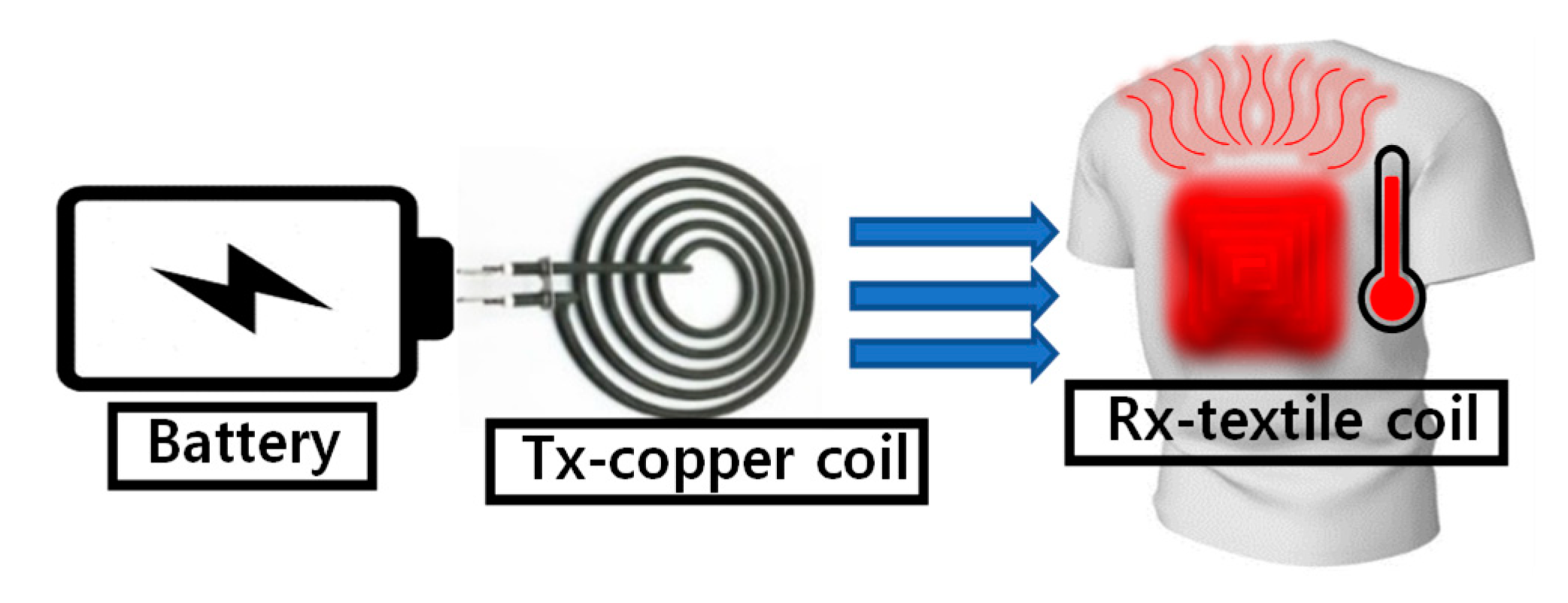
Inductive Power Transmission for Wearable Textile Heater using Series-None Topology

1
Department of Electrical Engineering, Incheon National University, Incheon 22012, Korea
2
Daegu Research Center for Medical Devices and Rehab Engineering, Korea Institute of Machinery and Materials, Daejeon 42994, Korea
*
Authors to whom correspondence should be addressed.
Electronics 2020, 9(3), 431; https://doi.org/10.3390/electronics9030431
Submission received: 10 February 2020 / Revised: 25 February 2020 / Accepted: 2 March 2020 / Published: 4 March 2020
(This article belongs to the Special Issue Wireless Power/Data Transfer, Energy Harvesting System Design)

Abstract

:
In this paper, an inductive-power-transmission (IPT) system for a wearable textile heater is proposed to comfortably provide heating to a user’s body. The conductive thread, which has high electrical resistance, was sewn into a receiver (Rx) coil on clothing to generate high temperature with a low current. The proposed wearable heaters are completely washable thanks to their nonmetallic materials, other than conductive threads in the clothing. We introduced series-none (SN) topology to eliminate a resonant capacitor in the wearable textile heater. A single resonant capacitor in a transmitter (Tx) in SN mode was implemented to resonate both Tx and Rx, resulting in increased power delivered to the load (PDL) while maintaining high-power transfer efficiency (PTE), comparable with conventional series-series (SS) topology. When the supply voltage of the power amplifier was 7 V, while the PTE of the SS and SN modes was 85.2% and 75.8%, respectively, the PDL of the SS and SN modes was 2.74 and 4.6 W, respectively.

1. Introduction

Recently, wearable heaters have attracted a lot of broad attention due to their potential applications in personal heating systems and healthcare management, such as thermotherapy [1,2,3]. In particular, thermotherapy has been effective in relieving pain and activating muscles or damaged skin, joints, and tissue, resulting in effective physiotherapy [3]. Most research on wearable heaters has typically focused on the development of heating materials for transparent [1], stretchable [1,2], or high-temperature (>100 °C) operations [3]. However, wearable heaters that were studied or commercialized still require electric wires to supply power to the thermal materials, which causes inconvenience and limited action for users. Inductive-power-transmission (IPT) technology could be a potential application in wearable heaters because IPT can eliminate electric wires from thermal materials in clothes.
IPT has been researched in the last few decades because of the convenience of wireless technology and its high applicability with other fields, such as the wireless charging of electric vehicles [4] and implantable biomedical devices [5,6]. In conventional IPT systems, many applications use a capacitive compensation network, such as series-series (SS) [7,8,9], series-parallel (SP) [8], parallel-series (PS) [10], and parallel-parallel (PP) [11,12], to improve power transfer efficiency (PTE) or power delivered to load (PDL) in given conditions. However, these compensated capacitors in a receiver (Rx) coil can be potentially damaged by repeated washing when it is implemented in a wearable textile heater with IPT technology.
While several IPT topologies were proposed to eliminate the resonant capacitor at the Rx [13] or the Tx [14], they inherently showed less PTE than the maximal achievable PTE of conventional compensation topologies. Series-none (SN) compensation, which removes the resonant capacitor at the Rx [13], ideally shows approximately the same PTE as that of SS topology, but only when the coupling is strong and quality (Q) factors are large, which is difficult to achieve in a textile coil. Therefore, the proposed IPT with a textile coil focused on the analysis of PTE and PDL losses from the SS topology to find an optimal design point, where PTE loss is not large, but the PDL is increased at the same level as power-amplifier (PA) supply voltage VDD, which implies the alleviation of voltage stress on the PA. Moreover, the SN structure has inherent advantages in terms of wireless efficiency and safety, because the overall system, including the Tx coil, only resonates when the textile Rx coil is properly coupled to the Tx, unlike in a conventional structure.
In the proposed wearable textile heater with an IPT system, a conductive thread (Imbut GmbH 110/f34_PA) with silver-coated polyamide multifilament yarns was utilized, which showed good electrical and thermal conductivity with good washability. We designed a textile coil by sewing the conductive thread onto the clothing. This textile coil simultaneously performs the roles of the Rx coil and thermal material [15]. The proposed wearable heater with an IPT system using a textile coil is shown in Figure 1. The PTE and PDL of the wearable textile heater in the IPT system were analyzed on the basis of circuit theory for conventional SS and proposed SN modes. The system modeling is described in Section 2, and experiment results are shown in Section 3. The conclusion is given in Section 4.

2. System Modeling

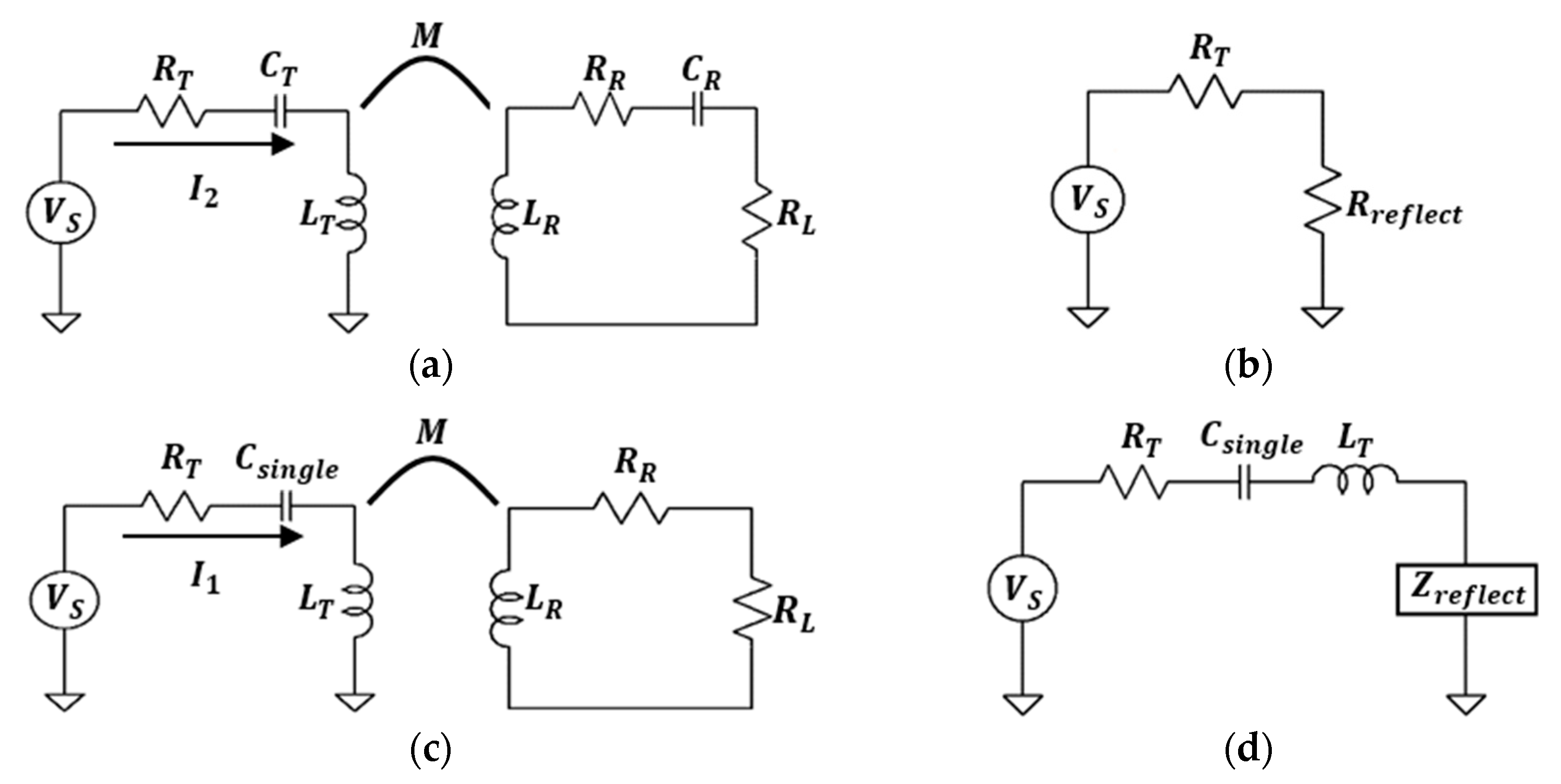
2.1. Circuit Analysis of SS and SN modes

In Figure 2a, the circuit model of SS is presented, which consisted of RT, CT, and LT, where LT is the inductance of the transmitter (Tx) coil, CT is a resonant capacitor of Tx, and RT is the combination of the parasitic resistance of the Tx coil, equivalent series resistance (ESR) of CT, and the output resistance of PA, represented in VS. The Rx was composed of RL, RR, CR, and LR, where LR is the inductance of the Rx coil, CR is a resonant capacitor of Rx, RR is a sum of the parasitic resistance and ESR of CR, and RL is load resistance [16].
Since resonant capacitors can compensate for the reactance of inductors from Tx and Rx coils, we could transform the SS circuit to a simple equivalent circuit as shown in Figure 2b. In SS topology, the reflected resistance at Tx is given by
R r e f l e c t , S S = k 2 Q T Q R R T ,
where k is coupling coefficient, and Q T = w L T / R T , Q R = w L R / ( R R + R L ), which are the Q factor of Tx and loaded Rx coils, respectively.
The transmission efficiency of SS topology can be calculated by the ratio of delivered power to the RT and Rreflext,SS, resulting in ηT,SS, given by
η T , S S = k 2 Q T Q R 1 + k 2 Q T Q R .
Similarly, Rx efficiency can also be calculated by the ratio of delivered power to the RR and RL, resulting in Rx efficiency ηR, given by
η R = 1 Q R Q R ,
where QR = ωLR/RR, which is the Q factor of the Rx coil. Consequently, the total efficiency of the SS mode can be calculated by the multiplication of ηT,SS and ηR:
η S S = k 2 Q T Q R 1 + k 2 Q T Q R ( 1 Q R Q R ) .
In Figure 2a, the source current can be derived as
I 2 , p k = V s , p k R T + R r e f l e c t , S S = V s , p k R T ( 1 + k 2 Q T Q R )
where I2,pk and Vs,pk are the peak current of the SS mode and peak source voltage, respectively. The input power of SS mode is obtained by
P i n , S S = 0.5 V s , p k I 2 , p k = 0.5 V s , p k 2 R T ( 1 + k 2 Q T Q R ) ,
and the output power of SS mode is defined as the multiplication of Pin,SS and ηSS:
P o u t , S S = k 2 Q T Q R ( 1 + k 2 Q T Q R ) 2 ( 1 Q R Q R ) ( V s , p k 2 2 R T ) .
In SN mode, there is no resonant capacitor in Rx, and the reactance part still remains in the equivalent circuit compared to SS mode, as shown in Figure 2c. In this condition, the reflected impedance can be written as
Z r e f l e c t = k 2 Q T Q R R T 1 + Q R 2 j k 2 Q T Q R 2 R T 1 + Q R 2 .
The reactance part of Zreflect can be compensated by a single capacitor at Tx, Csingle, and it is defined as
C s i n g l e = 1 w 2 L T ( 1 k 2 Q R 2 / ( 1 + Q R 2 ) ) .
The Equation (9) implies that the overall inductive link only resonates with Csingle when the Rx coil is properly coupled with the Tx coil. This is advantageous in terms of wireless power efficiency and safety compared to the conventional structure. Since LT does not directly resonate with Csingle, Tx power consumption without the Rx coil is automatically reduced.
Assuming that the reactance part is completely compensated by Csingle in SN mode, there was only reflected resistance Rreflect,SN remaining, as shown in Figure 2d, which can be defined as
R r e f l e c t , S N = k 2 Q T Q R R T 1 + Q R 2 .
The Rx efficiency of SN mode was the same as that of SS mode since there was no additional energy consumption in the inductance. Therefore, the remaining procedures to obtain the equations of PTE and PDL are similar to the SS mode:
η T , S N = k 2 Q T Q R 1 + Q R 2 + k 2 Q T Q R
η S N = k 2 Q T Q R 1 + Q R 2 + k 2 Q T Q R ( 1 Q R Q R ) ,
I 1 , p k = V s , p k R T ( 1 + k 2 Q T Q R / ( 1 + Q R 2 ) ) ,
P i n , S N = 0.5 V s , p k I 1 , p k = 0.5 V s , p k 2 R T ( 1 + k 2 Q T Q R / ( 1 + Q R 2 ) ) ,
P o u t , S N = k 2 Q T Q R ( 1 + Q R 2 ) ( 1 + Q R 2 + k 2 Q T Q R ) 2 ( 1 Q R Q R ) ( V s , p k 2 2 R T ) .
On the basis of the PTE and PDL from SS and SN modes in Equations (4) and (12), we introduced the ratios of PTE and PDL, nPTE and nPDL, to show the effectiveness of SN mode in a textile coil compared to the conventional SS mode:
n P T E = η S N η S S = 1 + k 2 Q T Q R 1 + Q R 2 + k 2 Q T Q R ,
n P D L = P o u t , S N P o u t , S S = ( 1 + Q R 2 ) ( 1 + k 2 Q T Q R ) 2 ( 1 + Q R 2 + k 2 Q T Q R ) 2 .
When nPTE or nPDL is close to 1, SN mode showed high PTE or PDL, the same as that in conventional SS mode, which means that SN mode could replace SS mode without an additional resonant capacitor in Rx. On the other hand, a small nPTE or nPDL implied that SN mode showed relatively lower achievable PTE or PDL compared to SS mode in the given wireless power conditions.

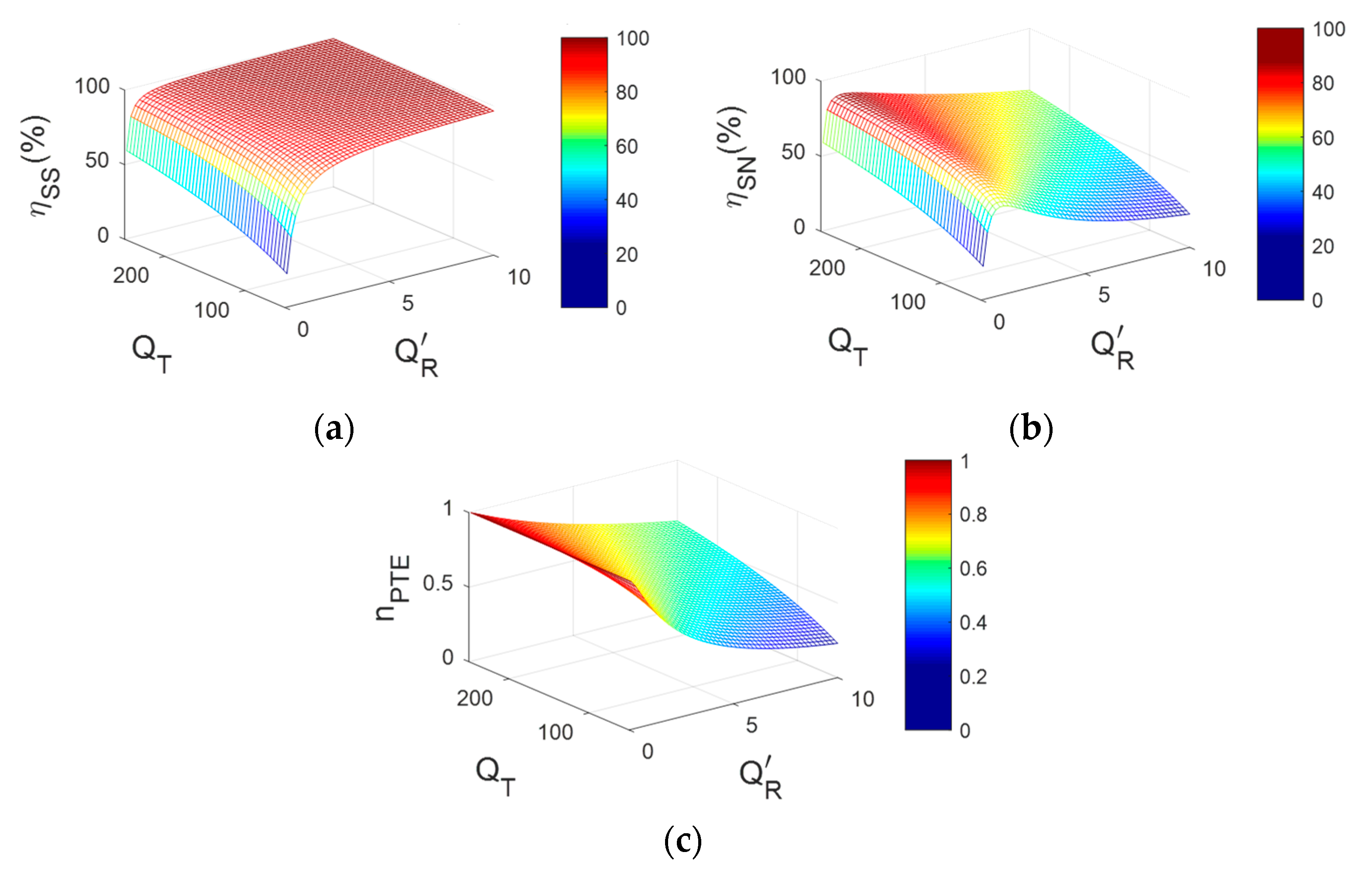
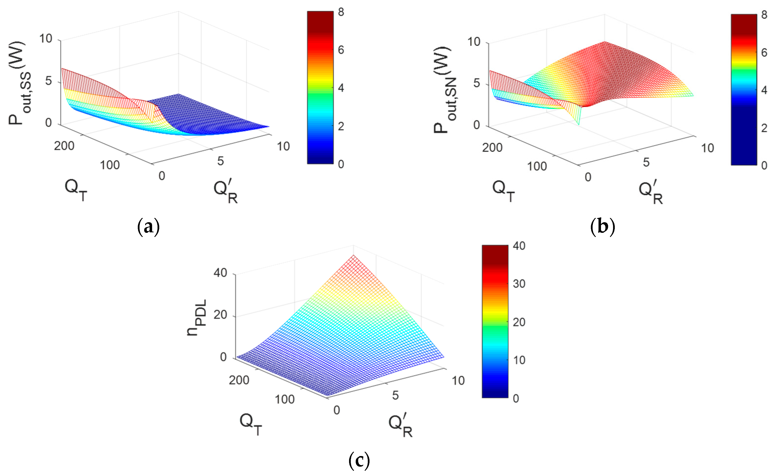
2.2. PTE and PDL Properties in SS and SN Modes

Figure 3 shows the calculated PTE in SS and SN modes, respectively, as a function of QT and Q R . QT is the effective Q factor of the Tx, including PA output resistance, 0.45 Ω. When the RL was much larger than RR, Rx efficiency ηR was close to 1. In the proposed wearable heater using the textile coil, RR could be considered as zero because the parasitic resistance of the Rx coil is regarded as the load resistance, resulting in the ηR ≈ 1. As shown in Figure 3a, ηSS increased when both QT and Q R increased. However, ηSN was maximized at the optimal Q R , which could be found from differentiating Equation (12), while higher QT was still desirable for the SN mode in Figure 3b. The achievable PTE ratio between SS and SN modes, nPTE, is shown in Figure 3c, and it was used to find the design consideration of Tx and Rx coils in SN mode. When nPTE was close to 1, it was beneficial to use SN mode instead of SS mode in the given inductive link considering the burden of the additional resonant capacitor in the Rx in SS mode.
By contrast with the PTE properties, the PDL in SS mode was maximized when Q R decreased, as shown in Figure 4a. This is because a larger Zreflect is not desirable for a large PDL, while it is beneficial for PTE, based on circuit theory. However, SN mode showed a higher PDL in a wide range of Q R compared to SS mode, as shown in Figure 4b, due to (1 + Q R 2 ) terms in Equation (15) compared to Equation (7). Therefore, the PDL ratio between SN and SS modes nPDL could be increased by up to ~60 as Q R increased, as shown in Figure 4c. Considering Figure 3c and Figure 4c, we could optimize the textile coil for a wearable heater in SN mode with improved PDL and less PTE loss compared to the conventional SS mode.

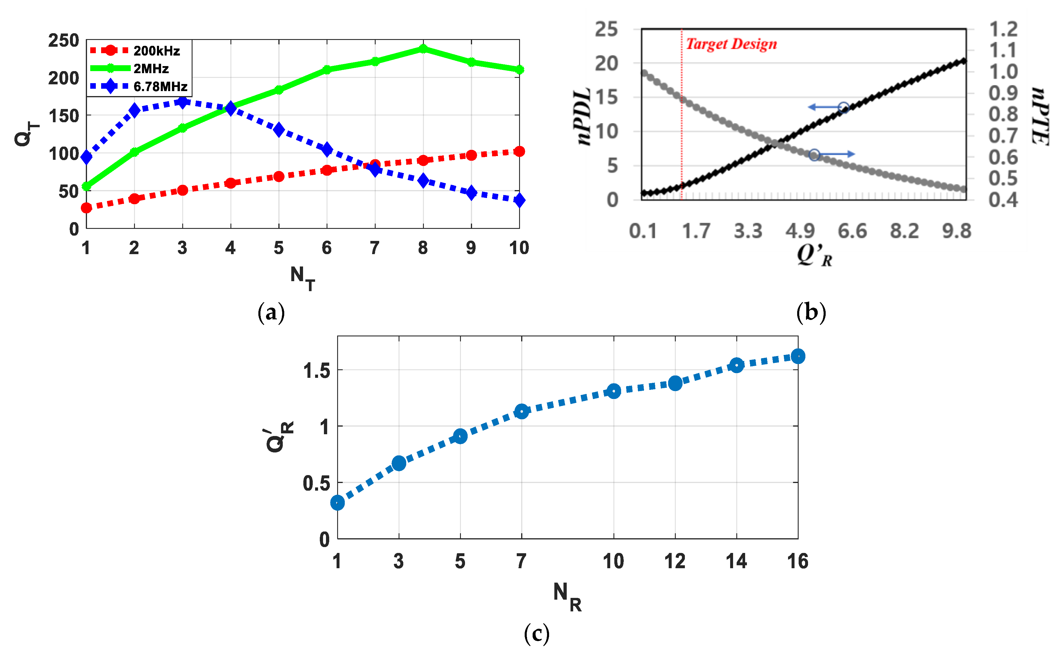
2.3. Coil Design for Wearable Textile Heater

Considering that the thermal material Rx, attached to the back of a t-shirt, received inductive power from the Tx in a backpack, the maximal outer diameter of the Tx and Rx coils was 16 cm with a gap of 4 cm between coils. In this condition, the coupling coefficient was 0.24, based on the calculation in [16], which was well-matched with the measurement result using the vector network analyzer. On the basis of the derived nPDL and nPTE in Figure 3c and Figure 4c, a higher QT is always desirable to achieve better PDL and PTE for fixed PA output resistance. Therefore, the Tx coil was designed to have maximal quality (Q) factor in the experiment conditions considering practical limitations. The Tx coil was designed using 22 American Wire Gauge (AWG) with a 0.3 mm pitch, with a sweep of frequencies and number of turns performed with an electromagnetic (EM) simulator (FEKO, Altair) and measurement, while the lumped-model circuit simulation was performed with LTSpice (Analog Devices). A Tx coil quality factor of 238 without PA output resistance (QT = 153.4 including PA) was achieved at NT = 8 at 2 MHz carrier frequency, as shown in Figure 5a. From the calculated result from Figure 3c and Figure 4c, Q R = 1 was selected considering optimal PTE loss (large nPTE) and improved PDL (large nPDL) in the textile coil. When Q R = 1, the PTE loss from the conventional SS structure was only 10%, while PDL was improved by 176%, as shown in Figure 5b. Although the figure of merit (FoM) between PDL and PTE could be one of clear standards as described in [17], the design balance between PDL and PTE is still flexible for the design purpose and applications. The Rx coil was designed using conductive thread with a 0.25 mm pitch at 2 MHz carrier frequency. The washable conductive thread (ELITEX®, Art. 110/f34_PA/Ag) had basic 110 dtex/34 filaments yarn counts with a silver coating of 1 μm thickness that showed 70 ± 20 Ω/m at DC and had a 259 °C melting point based on the datasheet. The number of turns of Rx coil NR was swept to find the optimal condition of Q R = 1. As shown in Figure 5c, NR = 7 showed the nearest value to 1. The coil parameters for Tx and Rx are summarized on Table 1. The coil parameters in Table 1 show one of the exemplar designs for the wireless wearable heater for t-shirts. While the outer diameters or thickness of coils could differ by geometrical limitations in practical applications such as gloves, socks, or t-shirts, the optimization procedure is the same as that of the SN topology.

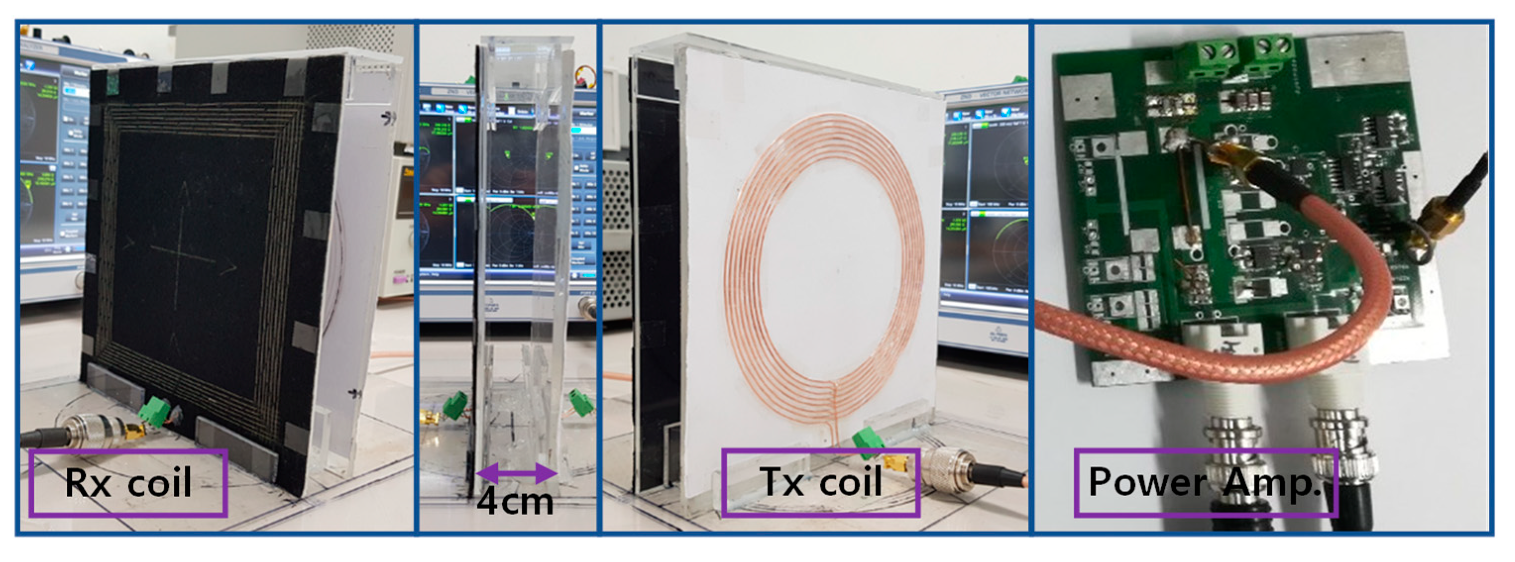
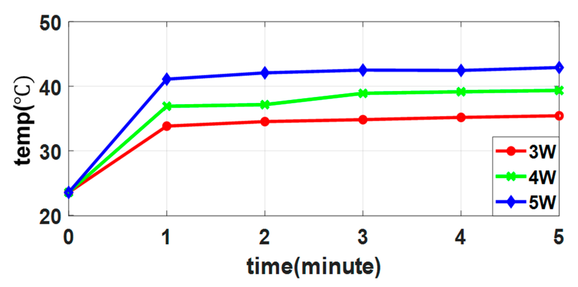
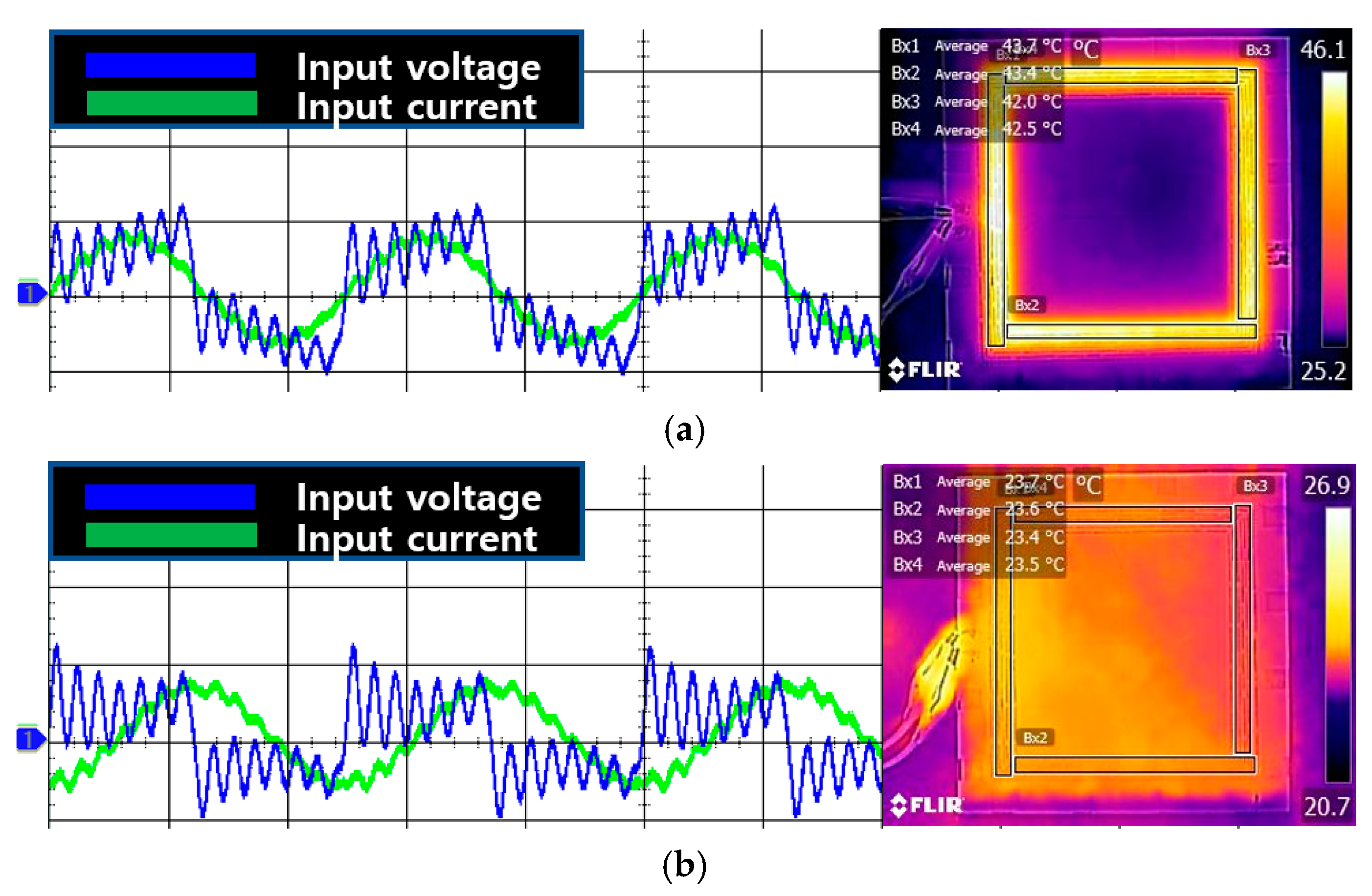
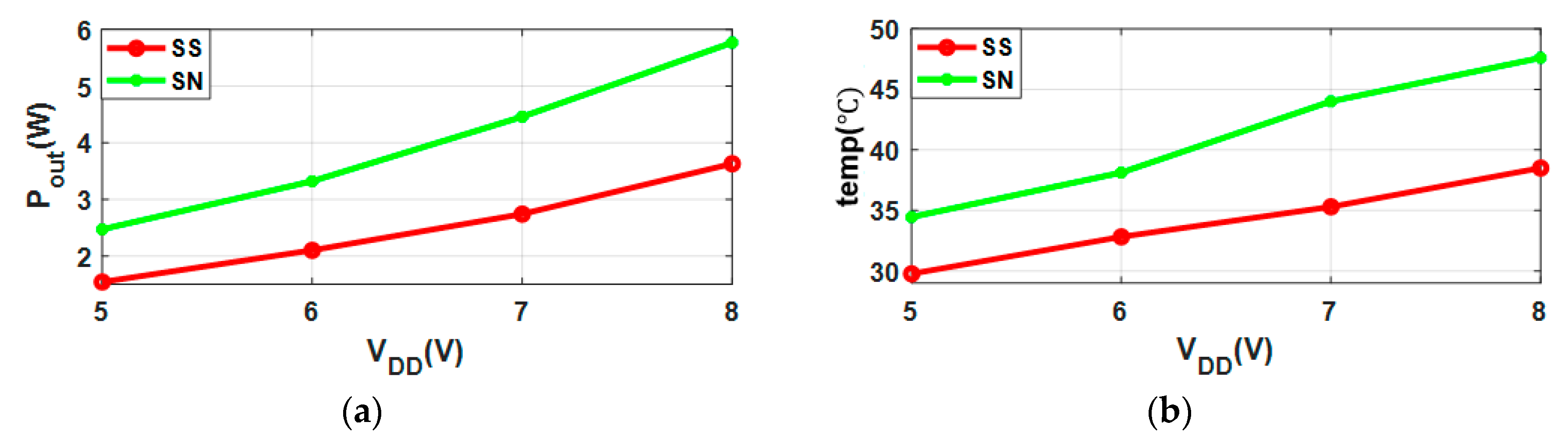
3. Experiment Results

Figure 6 shows the experiment setup for the optimized wire-wound Tx coil and conductive-thread Rx coil on the textile with a Class-D power amplifier (PA). The Tx coil was placed 4 cm away from the textile Rx coil, and the PA drove the Tx coil for the inductive heating. The Rx coil received inductive power from the Tx coil, and its internal resistance simultaneously operated as thermal material. The Rx coil made of conductive threads had an electrical resistance of 70 ± 20 Ω/m, allowable current of 0.4 A, and good washability. PA power was controlled by PA supply voltage VDD for the temperature controls in the wearable textile heater. The coupling coefficient of the proposed inductive link was 0.24 at 4 cm distance with QT = 153.4, including PA output resistance and Q R = 1.1 as shown in Table 2. All parameters and variables were acquired by the network analyzer (ZND, Rohde and Schwarz) in the experiment.
Figure 7 shows the measured temperature of the wearable textile heater depending on the controlled PA power from 3 to 5 W by the adjustment of VDD. Temperature was measured by thermal imaging camera, and was controlled by the input PA power and increased up to 42.5 °C from room temperature when the PA provided the output power of 5 W. For individual PA powers, temperature in the wearable textile heater reached the target temperature within 1 min.
Figure 8 shows the transient waveforms of input voltage and current waveforms in the PA with the temperature of the inductively powered wearable textile heater using the thermal imaging camera. When the textile Rx was properly placed on the Tx coil without any misalignment, the imaginary parts of Zreflect and LT resonated with Csingle at 2 MHz carrier frequency from the PA, as shown in Figure 2d. Therefore, the entire inductive link from the Tx to the Rx resonated in-phase between input voltage and current because the real parts of the inductive link remained, and the temperature in the wearable textile heater increased up to 42.5 °C from room temperature, as shown in Figure 8a. The PA did not automatically deliver the inductive power to the wearable textile heater when the Rx coil moved farther from the Tx coil. In this case, the imaginary parts of Zreflect were reduced compared to the nominal condition, and the resonant frequency of the Tx moved farther from the 2 MHz carrier frequency, resulting in an almost 90° phase shift between input voltage and current waveforms, shown in Figure 8b. Therefore, the temperature of the wearable textile heater stayed at room temperature, and the energy was rarely dissipated in this condition.
PTE and PDL were measured for the proposed system with SN mode, and compared to the conventional SS mode, as summarized on Table 2. The output impedance of the PA, 0.45 Ω, was added in the QT. While the measured PTE of the proposed SN mode was reduced by 11%, it showed a 1.6 times higher PDL on average compared to the SS mode without the compensated capacitor in the Rx coil, which showed similar trends in the calculated results. The derived equations proved reliability by showing that the error rate was within 10% between calculated and measured results. The error rates of ηSS, ηSN, and nPDL were 2.97%, 6.23%, and 10%, respectively. The measured PDLs and the temperatures of the wearable textile heater for SS and SN modes are shown in Figure 9 with respect to controllable PA supply voltage VDD.

4. Conclusions

We presented the new concept of a wearable heater that combines IPT techniques and a textile coil. The SN mode for the IPT was adapted in the proposed wearable textile heater to eliminate electronic components in the Rx, improving robustness and user convenience. Since the Tx coil only resonates with the textile Rx coil when both coils are properly placed, the system could save energy and ensure safety if the Rx coil is unintentionally misaligned during operation. We optimized the Tx and Rx coils to minimize PTE loss, and maximize the PDL in SN mode through analysis in the IPT system based on SN topology analysis for wireless-wearable-heater applications. The proposed system provides a very robust wearable heater using IPT technology without any electrical components at the Rx, which dramatically increases convenience for the user. Compared to the conventional SS topology in the IPT, the proposed optimized design showed 160% improved PDL, while PDL was only reduced by 11%, which was well-matched with the theoretical results. Furthermore, the proposed design could inherently prevent energy dissipation from the Tx against misalignment between Tx and Rx due to automatic resonant-frequency shifting in the IPT, resulting in improved safety and efficiency with no need for complicated sensing and data-communication circuitries in the Rx. Although the proposed wireless wearable heater showed less sensitivity against temperature variations compared to a wired wearable heater due to the lack of sensing circuitries in the Rx, it can be further improved by a transient observation circuit in the Tx to monitor input voltage and current for estimating the delivered power to the heating material, as shown in Figure 7. To the best of our knowledge, this is the first demonstration of a wireless wearable heater using conductive thread, providing textile-coil optimization for SN topology in an IPT system.

Author Contributions

conceptualization, B.L. and K.-H.L.; methodology, B.L.; validation, H.K. and B.L.; formal analysis, H.K.; investigation, B.L.; data curation, H.K.; writing—original-draft preparation, H.K.; writing—review and editing, B.L.; visualization, H.K.; supervision, project administration, and funding acquisition, B.L. All authors have read and agreed to the published version of the manuscript.

Funding

This work was supported by the Incheon National University (#2018-0165) Research Grant in 2018.

Conflicts of Interest

The authors declare no conflict of interest.

References

  1. Hong, S.; Lee, H.; Lee, J.; Kwon, J.; Han, S.; Suh, Y.D.; Cho, H.; Shin, J.; Yeo, J.; Ko, S.H. Highly stretchable and transparent metal nanowire heater for wearable electronics applications. Adv. Mater. 2015, 27, 4744–4751. [Google Scholar] [CrossRef] [PubMed]
  2. Choi, S.; Park, J.; Hyun, W.; Kim, J.; Kim, J.; Lee, Y.B.; Song, C.; Hwang, H.J.; Kim, J.H.; Hyeon, T.; et al. Stretchable heater using ligand-exchanged silver nanowire nanocomposite for wearable articular thermotherapy. ACS Nano 2015, 9, 6626–6633. [Google Scholar] [CrossRef] [PubMed]
  3. Zhang, M.; Wang, C.; Liang, X.; Yin, Z.; Xia, K.; Wang, H.; Jian, M.; Zhang, Y. Weft-Knitted Fabric for a Highly Stretchable and Low-Voltage Wearable Heater. Adv. Electron. Mater. 2017, 3, 1700193. [Google Scholar] [CrossRef]
  4. Liu, C.; Jiang, C.; Qiu, C. Overview of coil designs for wireless charging of electric vehicle. In Proceedings of the 2017 IEEE PELS Workshop on Emerging Technologies: Wireless Power Transfer (WoW), Chongqing, China, 20–22 May 2017; pp. 1–6. [Google Scholar]
  5. Jia, Y.; Mirbozorgi, S.A.; Lee, B.; Khan, W.; Madi, F.; Weber, A.; Li, W.; Ghovanloo, M. A mm-Sized Free-Floating Wirelessly-Powered Implantable Optical Stimulation Device. IEEE Trans. Biomed. Circuits Syst. 2019, 13, 608–618. [Google Scholar] [CrossRef]
  6. Lee, B.; Ahn, D. Robust Self-Regulated Rectifier for Parallel-Resonant Rx Coil in Multiple-Receiver Wireless Power Transmission System. IEEE J. Emerg. Sel. Top. Power Electron. 2019. [Google Scholar] [CrossRef]
  7. Lee, B.; Yeon, P.; Ghovanloo, M. A multi-cycle Q-modulation for dynamic optimization of inductive links. IEEE Trans. Ind. Electron. 2016, 63, 5091–5100. [Google Scholar] [CrossRef] [PubMed] [Green Version]
  8. Zhang, Z.; Pang, H.; Georgiadis, A.; Cecati, C. Wireless power transfer—An overview. IEEE Trans. Ind. Electron. 2018, 66, 1044–1058. [Google Scholar] [CrossRef]
  9. Sample, A.P.; Meyer, D.T.; Smith, J.R. Analysis, experimental results, and range adaptation of magnetically coupled resonators for wireless power transfer. IEEE Trans. Ind. Electron. 2011, 58, 544–554. [Google Scholar] [CrossRef]
  10. Monti, G.; Costanzo, A.; Mastri, F.; Monglardo, M. Optimal design of a wireless power transfer link using parallel and series resonators. Wirel. Power Transf. 2016, 3, 105–116. [Google Scholar] [CrossRef]
  11. Hu, A.P.; Hussmann, S. Improved power flow control for contactless moving sensor applications. IEEE Power Electron. Lett. 2004, 2, 135–138. [Google Scholar] [CrossRef]
  12. Monti, G.; Mastri, F.; Mongiardo, M.; Corchia, L.; Tarricone, L. Load-Independent Operative Regime for Inductive Resonant WPT Link in Parallel Configuration. IEEE Trans. Microw. Theory Technol. 2020, 1–10. [Google Scholar] [CrossRef]
  13. Zhang, Y.; Kan, T.; Yan, Z.; Mao, Y.; Wu, Z.; Mi, C.C. Modeling and Analysis of Series-None Compensation for Wireless Power Transfer Systems with a Strong Coupling. IEEE Trans. Power Electron. 2018, 34, 1209–1215. [Google Scholar] [CrossRef]
  14. Lee, B.; Kim, H.; Rim, C.T. Resonant power shoes for humanoid robots. In Proceedings of the 2011 IEEE Energy Conversion Congress and Exposition, Phoenix, AZ, USA, 17–22 September 2011; pp. 1791–1794. [Google Scholar]
  15. Šahta, I.; Baltina, I.; Truskovska, N.; Blums, J.; Deksnis, E. Selection of conductive yarns for knitting an electrical heating element. High Perform. Optim. Des. Struct. Mater. 2014, 137, 91–102. [Google Scholar]
  16. Harrison, R.R. Designing efficient inductive power links for implantable devices. In Proceedings of the 2007 IEEE International Symposium on Circuits and Systems, New Orleans, LA, USA, 27–30 May 2007; pp. 2080–2083. [Google Scholar]
  17. Kiani, M.; Ghovanloo, M. A Figure-of-Merit for Designing High-Performance Inductive Power Transmission Links. IEEE Trans. Ind. Electron. 2013, 60, 5292–5305. [Google Scholar] [CrossRef] [PubMed]
Figure 1. Simplified conceptual representation of proposed wearable heater using inductive power transmission with textile coil.
Electronics 09 00431 g001
Figure 2. (a) Circuit model of series-series (SS) topology, (b) simplified equivalent SS circuit model, (c) circuit model of proposed series-none (SN) topology, and (d) equivalent SN circuit model using textile coil.
Electronics 09 00431 g002
Figure 3. Calculated PTEs of (a) SS mode, ηSS, (b) SN mode, ηSN, and (c) PTE ratio of SS and SN modes, nPTE, as function of QT and Q R for k = 0.24 and RR = 0 Ω.
Electronics 09 00431 g003
Figure 4. Calculated PDLs of (a) SS mode, Pout,SS, (b) SN mode, Pout,SN and (c) PDL ratio of SS and SN modes, nPDL, as a function of function of QT and Q R for k = 0.24, RR = 0 Ω, and Vs,pk = 5 V.
Electronics 09 00431 g004
Figure 5. (a) Measured Q factor of wire-wound Tx coil for 200 kHz, 2 MHz, and 6.78 MHz carrier frequencies without power-amplifier (PA) output resistance; (b) Q R optimization for designated QT considering nPDL and nPTE; and (c) resulting Q factor of conductive-thread textile Rx coil vs. number of turns at 2 MHz carrier frequency.
Electronics 09 00431 g005
Figure 6. Experiment setup of optimized wire-wound Tx coil and conductive-thread textile Rx coil with power amplifier.
Electronics 09 00431 g006
Figure 7. Measured temperature curves of wearable textile heater for different PA power values.
Electronics 09 00431 g007
Figure 8. Transient waveforms of input voltage and current with temperature in wearable textile heater for (a) aligned and (b) misaligned Tx and Rx coils.
Electronics 09 00431 g008
Figure 9. Measured (a) power delivered to load (PDL) and (b) temperature of wearable textile heater for SS and SN modes with respect to controllable PA supply voltage VDD.
Electronics 09 00431 g009
Table 1. Parameters of transmitter (Tx) and receiver (Rx) coil.
Tx/Rx CoilParameters
MaterialOuter DiameterThicknessPitch (mm)TurnParasitic Res.Ind. (μH)Q
Tx coilCopper16 cm22 AWG0.380.82 Ω15.5238
Rx coilCoated Textile16 cm1 μm 10.257214.3 Ω18.31.1
1 Thickness of silver layer, 70 ± 20 Ω/m at DC.
Table 2. Calculated and measured results for SS and SN modes in wearable heater.
Fixed ParametersTopology
k Q T Q R Series-Series (SS)Series-None (SN)
0.24153.371.07
Calculated PTE90.7%81.8%
Measured PTE88%77%
Calculated n P D L 1.76
Measured n P D L 1.6

