Abstract
This paper presents not only a hardware-simulator development for hydraulic turbine generation systems (HTGS) in a district heating system (DHS) but also its control strategies and sequence. Generally, a DHS uses a differential pressure control valve (DPCV) to supply high-pressure–high-temperature fluids for customers depending on distance. However, long-term exposure of the DPCV to fluids increases the probability of cavitation and leads to heat loss in an event of cavitation. Therefore, a HTGS was introduced to solve this problem. It performs differential pressure control of the fluids, replaces the DPCV, and converts excess energy wasted by the DPCV to electrical energy. In this paper, the development of a hardware-simulator for HTGSs with a back-to-back converter, which uses two-level topologies, is proposed; moreover, control strategies and sequence used in this design are presented. The performance and validity of the proposed hardware-simulator and its control strategies are demonstrated by experimental results.
1. Introduction
The district heating system (DHS) is known to be efficient and reliable for heating and cooling buildings in densely populated cities, communities, and commercial facilities [1,2,3]. It supplies high pressure and temperature fluids to customers, as shown in Figure 1. However, because the pressure of fluids is decided relative to the distance from the cogeneration plant to the farthest customers, an additional device is required to decompress fluids that are supplied to customers that are closer the plant. Generally, a differential pressure control valve (DPCV) is used to supply fluids, depending on the distance between the cogeneration plants and customers [4]. It can control the differential pressure between the input and output of DPCV.
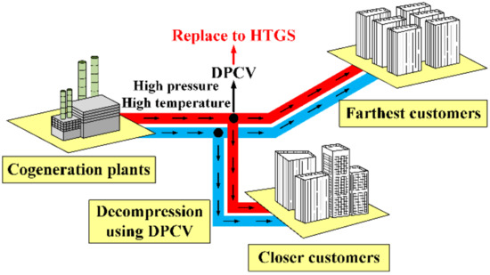
Figure 1.
Schematic diagram of district heating system (DHS). DCPV = differential pressure control valve; HTGS = hydraulic turbine generation systems.
However, in case the DPCV is exposed to high-pressure and temperature fluids over a long time, it increases the probability of cavitation, which can cause heat-loss and decreases the transfer efficiency of heat energy. Therefore, to solve the problem of DPCV in DHS and to utilize excess energy, the hydraulic turbine generation system (HTGS) as a replacement for DPCV has been studied [5]. Figure 2 shows the comparison of pressure regulation devices for high-pressure fluids in DHS. In DHS using DPCV as shown in Figure 2a, the pressure of high-pressure fluids flowing into the pipeline is decompressed by regulating flow rate using the DPCV. In DHS replacing DPCV with HTGS as shown in Figure 2b, the hydraulic turbine with a permanent magnet synchronous generator (PMSG) is installed in the middle of the pipeline without DPCV. The pressure of high-pressure fluids can be decompressed by controlling the torque of the PMSG coupled with the hydraulic turbine.
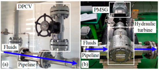
Figure 2.
Comparison of pressure regulation devices for high-pressure fluids in DHS: (a) DHS using DPCV; (b) DHS replacing DPCV with HTGS. PMSG = permanent magnet synchronous generator.
The HTGS is an urban energy harvesting technology that can maximize transmission power efficiency by getting close to cogeneration plants and customers [6,7,8,9,10,11]. It generally adopts a Pico Hydropower [12] with a rated power less than 5 kW. Additionally, contrary to Pico Hydropower in the river stream, cost of public works required to install the HTGS is not necessary because the DHS replacing DPCV with HTGS is generally located nearby customers. Therefore, it leads to initial investment saving, and it does not have effect on surrounding ecosystem; the unused energy wasted by DHS using DPCV can be utilized through DHS replacing DPCV with HTGS, as well.
The HTGS consists of a permanent magnet synchronous generator (PMSG) with a hydraulic turbine and a power conversion system (PCS) using a back-to-back (BTB) converter, as shown in Figure 3. Furthermore, an LCL filter for reducing the output of current ripples and a three-phase grid were connected to the PCS. The BTB converter consists of a generator-side inverter and grid-side converter [13,14,15,16] using two-level topologies [17,18] that share a DC-link. In HTGS, electrical energy is generated by the PMSG, when high-pressure fluids rotate the hydraulic turbine. This electrical energy can be transferred to the three-phase grid using the PCS [19,20,21,22]. As a result, HTGS performs differential pressure control of fluids, replaces DPCV, and converts unused energy wasted by DPCV to electrical energy.
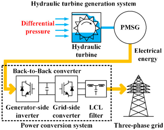
Figure 3.
Configuration of HTGS with back-to-back (BTB) converter.
In this paper, we propose a hardware-simulator development for HTGS with the BTB converter, which uses two-level topologies. It describes not only the design of the power and control board of the BTB converter but also controls its strategies and sequence. Experimental results demonstrate the performance and validity of the proposed hardware-simulator and control strategies.
2. Proposed Hardware-Simulator for HTGS
The proposed hardware-simulator for HTGS in DHS is composed of the PMSG with the hydraulic turbine and the BTB converter. The hydraulic turbine is modeled using a 5 kW induction motor, which is controlled by a conventional inverter (Yaskawa A1000). The BTB converter is classified into the generator-side inverter and the grid-side converter that are designed for the power and control board, respectively.
2.1. Power Board of Generator-Side Inverter
Figure 4 shows the power board of the generator-side inverter. The power board of the generator-side inverter is typically designed by using a switch module of the two-level topology, a snubber capacitor, a DC-link voltage sensor, current sensors, and DC-link capacitors. The switch module is designed by PM50CL1A120 (1200 V/50 A) from Mitsubishi; the module consists of six insulated gate bipolar transistors (IGBTs), gate drivers, and protection circuits. The current sensors are required to measure the currents of the PMSG, and they are designed by HC-PDG50V4B15 (50 A) from KOHSHIN. Additionally, the snubber capacitors are required to reduce spikes in DC-link current and voltage, and to reduce the electromagnetic interference (EMI) caused by voltage damping and current ringing. It is designed by PHE450 (1600 V/330 nF) from KEMET. Finally, the DC-link of the power board in the generator-side inverter is connected to that of the power board in the grid-side converter, and the DC-link voltage sensor measures the DC-link voltage.
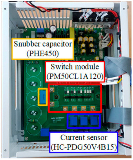
Figure 4.
Power board of generator-side inverter.
2.2. Power Board of Grid-Side Converter
Figure 5 shows the power board of the grid-side converter. The switch module, current sensors, snubber capacitor, DC-link capacitors, and the DC-link voltage sensor of the power board in the grid-side converter are equal to those of the power board in the generator-side inverter. However, because the power board of the grid-side converter is connected to the three-phase grid, additional components, such as voltage sensors and magnetic contactors (MCs), are required. The voltage sensors are required to measure the voltages of the three-phase grid; they are designed by SVH-D4-500H05-12D (1000 V) from Seri2B. Additionally, the MCs are required to connect the power board of the grid-side converter to the three-phase grid. They are designed by MC-22b (690 V/40 A) from LSIS.
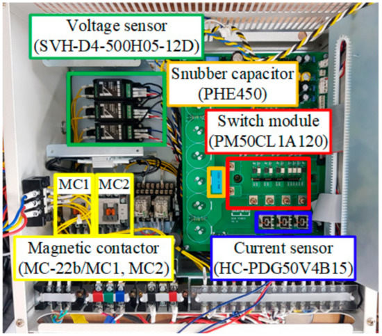
Figure 5.
Power board of grid-side converter.
Figure 6 shows the circuit diagram of MCs in the power board of the grid-side converter. The MCs branch out into two types, namely MC1 for initial charging circuit and MC2 for direct connection circuit. Furthermore, the resistors (RMC,ic) are connected to the initial charging circuit in series. Therefore, when the power board of the grid-side converter is initially connected to the three-phase grid, MC1 is switched on to prevent the inrush current of DC-link capacitors. After a few seconds, MC2 is switched on for a direct connection between the power boards of the grid-side converter. Then, MC1 is switched off.
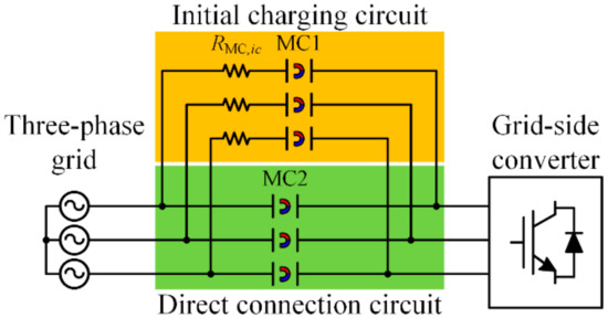
Figure 6.
Circuit diagram of magnetic contactors (MCs) in power board of grid-side converter.
2.3. Control Board of BTB Converter
In the proposed hardware-simulator for HTGS, the BTB converter adopts two control boards for the generator-side inverter and the grid-side converter, respectively. Each control board of the BTB converter is equal. Figure 7 shows the control board of the BTB converter, which is typically designed by using a digital signal processor (DSP), JTAG, RS232, relay signal, RS485, enhanced quadrature encoder pulse (eQEP), and other peripheral circuits.
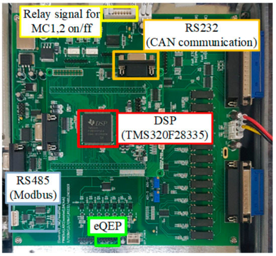
Figure 7.
Control board of BTB converter. CAN = controller area network; eQEP = enhanced quadrature encoder pulse.
The DSP is necessary for whole calculations: measuring voltages and currents, as well as control implementations, in the control board of the proposed hardware-simulator for HTGS. It is designed by TMS320F28335 as a high-performance controller from Texas Instruments. The TMS320F28335 is operated as 150 MHz clocks, and it has 12 ports of PWM and 16 channels of an analog-to-digital converter (ADC) [23,24]. The 6 ports of PWM in each control board of the BTB converter are used to operate the switch module in each power board of the generator-side inverter and grid-side converter. Additionally, the 4 channels or 7 channels of ADC in each control board of the BTB converter are used to measure DC-link voltage, three-phase currents of the PMSG or the three-phase grid, and voltages of the three-phase grid in each power board of the generator-side inverter and grid-side converter.
Figure 8 shows a functional block diagram of the control board with a host controller unit. In the proposed hardware-simulator, the JTAG of SDS200i from Syncworks is used to connect the control board to the computer. The controller area network (CAN) communication, which exchanges information between each control board of the generator-side and grid-side converter, uses RS232 for serial communication. The relay signals and RS485 are only used in the control board of the grid-side converter. The relay signals are used to operate the MCs, as shown in Figure 6. RS485 is used for Modbus communication to exchange start or stop signals for the operation of the PCS between the control board of the grid-side converter and the host controller unit. The eQEP is used only in the control board of the generator-side inverter and to calculate the rotational angle and speed of the PMSG. Finally, there are other peripheral circuits for isolation circuits and protection circuits.
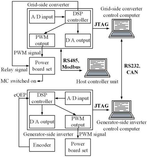
Figure 8.
Function block diagram of control board with host controller unit.
3. Control Strategies and Sequence of BTB Converter
Figure 9 shows the control block diagram of HTGS with the BTB converter. In HTGS, the electrical energy generated from the PMSG as an alternating current (AC) power is converted to direct current (DC) power using the generator-side inverter [25]. The converted DC power is reconverted to the AC power by the grid-side converter. The DC-link reduces the ripple of converted DC power. The control strategies of HTGS is described by dividing the generator-side inverter and grid-side converter [26,27]. The generator-side inverter controls the torque of the PMSG to perform differential pressure control of the high-pressure fluids. Moreover, the grid-side converter performs the DC-link voltage and current control [28]. As a result, the DC-link voltage of the BTB converter is continuously controlled, and the power generated by differential pressure control is transferred to the three-phase grid.
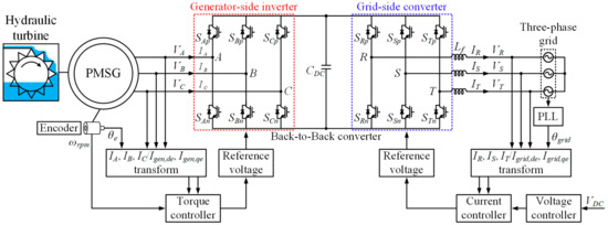
Figure 9.
Control block diagram of HTGS with BTB converter.
Figure 10 shows the control sequence of HTGS with the BTB converter. First, in the grid-side converter, the relay signal is switched on to operate the MCs as shown in Figure 6 and to connect the power board of the grid-side converter to the three-phase grid. Then, phase-locked loop (PLL) control is performed to calculate the phase angle of the three-phase grid. If the PLL control is operated appropriately, the voltage controller and current controller are turned on, and the reference DC-link voltage is applied. Finally, the switching operation of the grid-side converter is performed. The DC-link voltage controlled by the grid-side converter is applied to the DC-link of the power board in the generator-side inverter because the DC-link of the power board in the grid-side converter is directly connected to that of the power board in the generator-side inverter. Then, in the generator-side inverter, the current controller is turned on, and the reference current of the PMSG is applied. Finally, the switching operation of the generator-side inverter is performed.
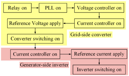
Figure 10.
Control sequence of HTGS with BTB converter. PLL = phase-locked loop.
4. Experimental Results
In this study, the proposed hardware-simulator for HTGS was built, as shown in Figure 11. The proposed hardware-simulator consists of the generator-side inverter, the grid-side converter, a grid-simulator, the PMSG connected with an induction motor, and a power analyzer. Table 1 shows the PMSG and system parameters used for the proposed hardware-simulator.
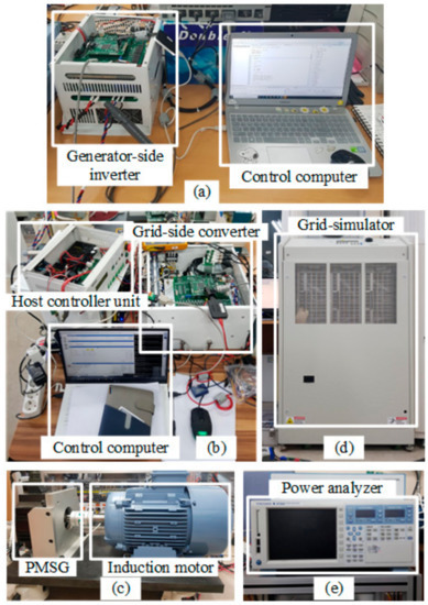
Figure 11.
Proposed hardware-simulator for HTGS: (a) generator-side inverter; (b) grid-side converter with host controller unit; (c) grid-simulator; (d) PMSG connected with induction motor; (e) power analyzer.

Table 1.
PMSG and system parameters.
Figure 12 shows the experimental results of the voltage control, using the grid-side converter with a control sequence. The state of the control sequence (Grid-side sequence) is changed to 6 from 0 depending on the control sequence of the grid-side converter, as shown in Figure 10. The DC-link voltage (VDC) is kept constant at 600 V using the voltage control of the grid-side converter. Additionally, VR and IR indicate the R-phase voltage and current of the three-phase grid, respectively. In Grid-side sequence 1, the MCs are operated to connect the initial charge circuit or direct connect circuit, depending on the relay signals. In Grid-side sequence 2 and 3, PLL control is performed to calculate the phase angle of the three-phase grid, and the calculated phase angle is checked, respectively. If the PLL control is typically operated, in Grid-side sequence 4, the voltage and current controller are turned on, and the reference DC-link voltage is adjusted to 600 V. Finally, in Grid-side sequence 5, the switching operation of the grid-side converter is performed. In Grid-side sequence 6, the overall control of the grid-side converter is checked.
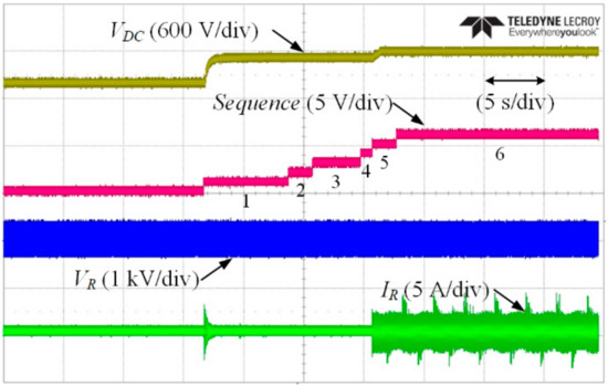
Figure 12.
Experimental results of voltage control using grid-side converter with control sequence.
Figure 13 shows the experimental results of the current control, using the generator-side inverter with a control sequence after the voltage control using the grid-side converter. The state of the control sequence (Generator-side sequence) is changed to 7 from 0 depending on the control sequence of the generator-side inverter, as shown in Figure 10. IA and Igen,qe indicate the A-phase current and q-axis current of the generator-side inverter, respectively. In Generator-side sequence 1, VDC of the generator-side inverter shared with the DC-Link of grid-side converter is checked. In Generator-side sequence 2 and 3, the PMSG is aligned by applying d-axis current. In Generator-side sequence 4, the current controller is turned on and the reference current is applied. Thereafter, the induction motor which modeled hydraulic turbine is rotated using Yaskawa A1000 in Generator-side sequence 5. If the PMSG connected to the induction motor rotates with constant speed, the switching operation of the generator-side inverter is performed. Finally, in Generator-side sequence 6 and 7, the overall control of the generator-side inverter is checked.
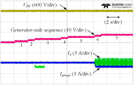
Figure 13.
Experimental results of current control using generator-side inverter with control sequence.
Figure 14 shows the experimental results of the voltage and current control using the grid-side converter. The phase angle (θgrid) of the three-phase grid is calculated by the PLL control and it can be checked by comparing it with the phase angle of the VR. The VDC is kept constant at 600 V, and the q-axis current (Igrid,qe) of the three-phase grid is controlled to 10 A, which is determined by the power generated from the PMSG. Additionally, as shown in Figure 14, the grid-side converter has a unity power factor because the phase difference between VR and IR is almost zero.
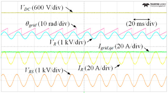
Figure 14.
Experimental results of voltage and current control using the grid-side converter.
Figure 15 shows the experimental results of the current control using the generator-side inverter. The VDC controlled by the grid-side converter is indicated as DC-link voltage of the generator-side inverter. In case the grid-side converter is conventionally performed, the PMSG connected with the hydraulic turbine modeled by an induction motor is rotated by using the common inverter. The speed (ωrpm) of the PMSG is set to 1800 rpm. Furthermore, the reference current of the PMSG is set to –19 A, and q-axis current (Igen,qe) of the PMSG is controlled to the reference current. As a result, in the proposed hardware-simulator, the power generated from the PMSG is transferred to the three-phase grid.
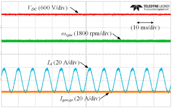
Figure 15.
Experimental results of current control using the generator-side inverter.
Figure 16 shows the experimental results of the BTB converter performance, using the power analyzer. Figure 16a,b show the current and power of the PMSG and three-phase grid, respectively. The power generated from the PMSG is about 5.2 kW, which is calculated by using the current and electro motive force (EMF) of the PMSG and the power transferred to the three-phase grid is about 4.8 kW, which is calculated by using the current and voltage of the three-phase grid. Moreover, as shown in Figure 16c,d, the current THD of the three-phase grid is approximately 2%, the power factor is 0.99, and the efficiency of the BTB converter is about 92%. The efficiency of the BTB converter is calculated by the ratio of the power generated from the PMSG and the power transferred to the three-phase grid, and it means that the conduction loss and switching loss generated by the PCS, including the grid-side converter and generator-side inverter, are approximately 0.4 kW. Consequently, the performance and validity of the proposed hardware-simulator and control strategies are validated by experimental results.
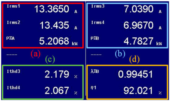
Figure 16.
Experimental results of BTB converter performance, using power analyzer. (a) Current and power of PMSG; (b) current and power of three-phase grid; (c) current THD of three-phase grid; (d) power factor and efficiency of BTB converter.
5. Conclusions
In this paper, the development of a hardware-simulator for HTGS in DHS was described. The HTGS is used to solve the failure of DPCV, such as cavitation, in DHS. The HTGS replaces DPCV, performs differential pressure control of the fluids, and converts excess energy wasted by DPCV to electrical energy. This paper presents the development and implementation of the hardware-simulator with the BTB converter, including the power and control boards, as well as its control strategies with control sequences. In addition, a 5 kW hardware-simulator was built in the laboratory with a grid-simulator and hydraulic turbine, which was modeled by an induction motor. Through the proposed hardware-simulator for HTGS, the power generated from the PMSG can be transferred to the three-phase grid. The performance and validity of the proposed hardware-simulator and control strategies were demonstrated by experimental results.
Author Contributions
K.-B.L. provided guidance and supervision. Y.B. conceived the idea of this paper and performed the experiment. Y.J.L. built hardware-simulator and performed the experiment. S.-S.J. implemented the main research, performed the experiment, wrote the paper and revised the manuscript as well. All authors have equally contributed to the experiment and result discussions. All authors have read and agreed to the published version of the manuscript.
Funding
This research was supported by a grant (No.20172020108970) from the Korea Institute of Energy Technology Evaluation and Planning (KETEP) that was funded by the Ministry of Trade, Industry and Energy (MOTIE) and the Korea Institute of Energy Technology Evaluation and Planning (KETEP) grant funded by the Korea government (MOTIE) (No.20182410105160, Demonstration and Development of ESS Solution Connected with Renewable Energy against with the wheather condition of Middle East Region).
Acknowledgments
Authors thank our Power Electronics Laboratory colleagues of Electrical & Computer Engineering Department, Ajou University, South Korea.
Conflicts of Interest
The authors declare no conflict of interest.
References
- Verrilli, F.; Srinivasan, S.; Gambino, G.; Canelli, M.; Himanka, M.; Vecchio, C.D.; Sasso, M.; Glielmo, L. Model predictive control-based optimal operations of district heating system with thermal energy storage and flexible loads. IEEE Trans. Autom. Sci. Eng. 2017, 14, 547–557. [Google Scholar] [CrossRef]
- Cao, Y.; Wei, W.; Wu, L.; Mei, S.; Shahidehpour, M.; Li, Z. Decentralized operation of interdependent power distribution network and district heating network: A market-driven approach. IEEE Trans. Smart Grid 2019, 10, 5374–5385. [Google Scholar] [CrossRef]
- Li, J.; Lin, J.; Song, Y.; Xing, X.; Fu, C. Operation optimization of power to hydrogen and heat (P2HH) in ADN coordinated with the district heating network. IEEE Trans. Sustain. Energy 2019, 10, 1672–1683. [Google Scholar] [CrossRef]
- Niu, S.; Wang, J.; Zhang, P.; Zhao, J.; Wang, S.; Shen, W. An energy-saving position control strategy for electro-hydraulic servo system with parallel dual valves. In Proceedings of the IEEE Chinese Control Conference (CCC), Guangzhou, China, 27–30 July 2019; pp. 3266–3271. [Google Scholar]
- Jeon, S.-S.; Bak, Y.; Lee, K.-B. Minimization of DC-link voltage variation in a hydraulic turbine generation system using back-to-back converters. Trans. Korean Inst. Electr. Eng. 2019, 68, 1118–1123. [Google Scholar] [CrossRef]
- Hajikhani, M.; Labeau, F.; Agba, B.L. An autonomous wireless sensor network in a substation area using wireless transfer of energy. IEEE Access 2018, 6, 62352–62360. [Google Scholar] [CrossRef]
- Hajikhani, M.; Labeau, F.; Agba, B.L. Power allocation for a self-sustainable power substation monitoring system using wireless transfer of energy. IEEE Access 2019, 7, 141456–141465. [Google Scholar] [CrossRef]
- Zhang, C.; Yang, M.; Li, J. Detailed modelling and parameters optimisation analysis on governing system of hydro-turbine generator unit. IET Gener. Transm. Distrib. 2017, 12, 1045–1051. [Google Scholar] [CrossRef]
- Liu, J.; Xu, B.; Chen, D.; Li, J.; Gao, X.; Liu, G. Grid-connection analysis of hydro-turbine generator unit with stochastic disturbance. IET Renew. Power Gener. 2018, 13, 500–509. [Google Scholar] [CrossRef]
- Joseph, A.; Kim, S.-M.; Lee, S.S.; Dominic, A.; Lee, K.-B. Boost multi-level NPC-fed VS large rated asynchronous pumped storage hydro-generating unit. IET Electr. Power Appl. 2019, 13, 1488–1496. [Google Scholar] [CrossRef]
- Fan, Z.-N.; Han, L.; Liao, Y.; Xie, L.-D.; Wen, K.; Wang, J.; Dong, X.-C.; Yao, B. Effect of Shifting the Pole-shoe and Damper-bar Centerlines on the No-load Voltage Waveform of a Tubular Hydro-generator. J. Electr. Eng. Technol. 2018, 13, 1294–1303. [Google Scholar]
- Thankappan, A.T.; Simon, S.P.; Nayak, P.S.R.; Sundareswaran, K.; Padhy, N.P. Pico-hydel hybrid power generation system with an open well energy storage. IET Gener. Transm. Distrib. 2017, 11, 740–749. [Google Scholar] [CrossRef]
- Baek, J.; Kwak, S. Direct power control of PMa-SynRG with back-to-back PWM voltage-fed drive. J. Electr. Eng. Technol. 2018, 13, 761–768. [Google Scholar]
- Tcai, A.; Shin, H.-U.; Lee, K.-B. DC-link capacitor-current ripple reduction in DPWM-based back-to-back converters. IEEE Trans. Ind. Electron. 2018, 65, 1897–1907. [Google Scholar] [CrossRef]
- Lee, J.-S.; Lee, K.-B.; Blaabjerg, F. Open-switch fault detection method of a back-to-back converter using NPC topology for wind turbine systems. IEEE Trans. Ind. Appl. 2015, 51, 325–335. [Google Scholar] [CrossRef]
- Zhang, Z.; Li, Z.; Kazmierkowski, M.P.; Rodriguez, J.; Kennel, R. Robust predictive control of three-level NPC back-to-back power converter PMSG wind turbine systems with revised predictions. IEEE Trans. Power Electron. 2018, 33, 9588–9598. [Google Scholar] [CrossRef]
- Lee, C.-H.; Lee, J. An optimal damping control algorithm of direct two-level inverter for miniaturization and weight reduction of auxiliary power supply on railway vehicle. J. Electr. Eng. Technol. 2018, 13, 2335–2343. [Google Scholar]
- Zhang, T.; Chen, X.; Qi, C.; Lang, Z. Leg-by-leg-based finite-control-set model predictive control for two-level voltage-source inverters. J. Power Electron. 2019, 19, 1162–1170. [Google Scholar]
- Bak, Y.; Lee, K.-B. Constant speed control of a permanent-magnet synchronous motor using a reverse matrix converter under variable generator input conditions. IEEE J. Emerg. Sel. Top. Power Electron. 2018, 6, 315–326. [Google Scholar] [CrossRef]
- Bak, Y.; Lee, K.-B. Reducing switching losses in indirect matrix converter drives: Discontinuous PWM method. J. Power Electron. 2018, 18, 1325–1335. [Google Scholar]
- Bak, Y.; Jang, Y.; Lee, K.-B. Torque predictive control for permanent magnet synchronous motor drives using indirect matrix converter. J. Power Electron. 2019, 19, 1536–1543. [Google Scholar]
- Jlassi, I.; Cardoso, A.J.M. Fault-tolerant back-to-back converter for direct-drive PMSG wind turbines using direct torque and power control techniques. IEEE Trans. Power Electron. 2019, 34, 11215–11227. [Google Scholar] [CrossRef]
- Jo, S.-R.; Kim, S.-M.; Cho, S.; Lee, K.-B. Development of a hardware simulator for reliable design of modular multilevel converters based on junction-temperature of IGBT modules. Electronics 2019, 8, 1127. [Google Scholar] [CrossRef]
- Park, K.; Lee, K.-B. Hardware simulator development for a 3-parallel grid-connected PMSG wind power system. J. Power Electron. 2010, 10, 555–562. [Google Scholar] [CrossRef]
- Lee, J.-S.; Lee, K.-B.; Blaabjerg, F. Predictive control with discrete space-vector modulation of Vienna rectifier for driving PMSG of wind turbine systems. IEEE Trans. Power Electron. 2019, 34, 12368–12383. [Google Scholar] [CrossRef]
- Lee, K.-B. Advanced Power Electronics, 1st ed.; Munundang: Seoul, Korea, 2019; pp. 141–210. [Google Scholar]
- Jeong, H.-G.; Lee, K.-B. Power Electronics Technology of Wind Power Generation System, 1st ed.; Hanteemedia: Seoul, Korea, 2014; pp. 56–75. [Google Scholar]
- Bak, Y.; Lee, J.-S.; Lee, K.-B. Low-voltage ride-through control strategy for a grid-connected energy storage system. Appl. Sci. 2018, 8, 57. [Google Scholar] [CrossRef]


© 2020 by the authors. Licensee MDPI, Basel, Switzerland. This article is an open access article distributed under the terms and conditions of the Creative Commons Attribution (CC BY) license (http://creativecommons.org/licenses/by/4.0/).