Article

NoCGuard: A Reliable Network-on-Chip Router Architecture

by
Muhammad Akmal Shafique
1,
Naveed Khan Baloch
2,
Muhammad Iram Baig
1,
Fawad Hussain
2,
Yousaf Bin Zikria
3,* and
Sung Won Kim
3,*
1
Department of Electrical Engineering, University of Engineering & Technology, Taxila 47050, Pakistan
2
Department of Computer Engineering, University of Engineering & Technology, Taxila 47050, Pakistan
3
Department of Information and Communication Engineering, Yeungnam University, Gyeongsan 38541, Korea
*
Authors to whom correspondence should be addressed.
Electronics 2020, 9(2), 342; https://doi.org/10.3390/electronics9020342
Submission received: 18 December 2019 / Revised: 7 February 2020 / Accepted: 12 February 2020 / Published: 17 February 2020

Abstract

:
Aggressive scaling in deep nanometer technology enables chip multiprocessor design facilitated by the communication-centric architecture provided by Network-on-Chip (NoC). At the same time, it brings considerable challenges in reliability because a fault in the network architecture severely impacts the performance of a system. To deal with these reliability challenges, this research proposed NoCGuard, a reconfigurable architecture designed to tolerate multiple permanent faults in each pipeline stage of the generic router. NoCGuard router architecture uses four highly reliable and low-cost fault-tolerant strategies. We exploited resource borrowing and double routing strategy for the routing computation stage, default winner strategy for the virtual channel allocation stage, runtime arbiter selection and default winner strategy for the switch allocation stage and multiple secondary bypass paths strategy for the crossbar stage. Unlike existing reliable router architectures, our architecture features less redundancy, more fault tolerance, and high reliability. Reliability comparison using Mean Time to Failure (MTTF) metric shows 5.53-time improvement in a lifetime and using Silicon Protection Factor (SPF), 22-time improvement, which is better than state-of-the-art reliable router architectures. Synthesis results using 15 nm and 45 nm technology library show that additional circuitry incurs an area overhead of 28.7% and 28% respectively. Latency analysis using synthetic, PARSEC and SPLASH-2 traffic shows minor increase in performance by 3.41%, 12% and 15% respectively while providing high reliability.

1. Introduction

A conventional way to increase chip performance is to improve its operational frequency. However, the power consumption of a chip shares a linear relationship with its operating frequency. It forces the designers to search for other ways to increase performance without exponentially increasing power consumption. Aggressive technology scaling in a deep nanometer regime enables the fabrication of billions of transistors on a chip [1]. This led to the design of chip multi-processors (CMP) or multi-core architectures with high performance and low power consumption [2].
CMPs typically use the on-chip bus for communication among two or four cores. The on-chip bus lacks scalability and does not support simultaneous communication among multiple cores. With the increasing multitude of cores, communication among the cores become more critical. The on-chip bus was unable to perform stringent communication, creating a bottleneck in performance growth. Consequently, it shifts the trend from the computational centric design to communication-centric design and has led to the evolution of on-chip interconnection network or network-on-chip (NoC) [3,4]. NoC architecture is a packet-based inter-connected network that separates communication from the computation. As it is different from the shared bus, it facilitates customization in terms of bandwidth, buffers size, and topology. It offers scalability without using long global wires. NoC infrastructure consists of routers and links that are used to deliver packets via layered protocol [5].
The continuous improvement in process technology yields higher transistor density [1]. It makes transistors and links more vulnerable to different fault mechanisms [6,7]. A fault in a transistor may lead to erroneous computation. Open/short circuit in links, result in data corruption. Even single fault can paralyze the whole chip. Primarily, faults are classified into permanent and transient categories [8]. Permanent faults are also known as hard faults, apparent in the chip for a lifetime after their occurrence. They permanently affect the functionality of the chip. They are traditionally caused by open/short circuits in links, time-dependent-dielectric-breakdown (TDDB) [9], electro-migration (EM) [10], stress migration, negative-bias-temperature-instability (NBTI) [11], hot carrier injection [12] and thermal cycling [13]. On the other hand, transient faults, also known as soft errors, occur only for one or two clock cycles. They are traditionally caused by electrical noise, electrostatic discharge, electrical power drops, overheating, mechanical shocks, process variation [14], and external radiations like alpha particles [15,16] and cosmic rays [17].
Each node in NoC connects with a processing element (PE) or memory unit through a router. The healthy core connected to the router become inaccessible in case of a router failure. Faults in the router architecture lead to misrouting, deadlock, traffic hot spots, packet loss, and increased latency. Thus, reliable router architecture is necessary to avoid these undesirable fault scenarios [18,19]. We focused only on the tolerance of permanent faults in the router micro-architecture. Previously, many routing techniques are proposed for permanent fault tolerance, they ignore healthy cores and make them inoperable [20,21]. We work on the permanent fault tolerance mechanism for each pipeline stage of the router. It ensures connectivity of the healthy core associated with the faulty router. The proposed methodology exploits idle cycles of existing resources, the default winner strategy for failed arbiters, and bypassing of faulty resources by providing multiple bypass paths. The dominant idea in this work is to get the right balance between redundancy techniques to get higher reliability at low latency overhead.
The rest of the paper is organized as follows; Section 2 presents the overview of existing reliable router architectures and fault detection mechanisms. Section 3 presents the fundamentals of a generic NoC router. Section 4 presents the effects of faults on router pipeline. Section 5 presents the proposed NoCGuard reliable router architecture. Section 6 presents the performance analysis. Section 7 presents the reliability analysis. Section 8 presents the latency analysis. Section 9 concludes the paper.

2. Related Work

BulletProof router [22] exploits N-modular redundancy (NMR) which requires multiple copies of the hardware for fault tolerance. It uses redundant components at every stage. However, it incurs high area and power overhead. RoCo router [23] splits the router into two independent row and column modules. Each module deals with one dimension, i.e., X or Y. Fault in one module does not affect the functionality of the other module. Thus, it tolerates faults with degraded performance.
Vicis router [24] exploits input port swapping and adaptive routing algorithm to tolerate faults in inter-router links. To tolerate faults in the data path of a router, i.e., intra-router links, crossbar (XB), and virtual channel (VC) buffers, it uses error correcting codes (ECC) and crossbar bypass bus. Encoder and decoder are placed at the input port. ECC can tolerate only one fault in the data path. Therefore, input port swapper and bypass bus use reconfiguration to avoid or move additional faults to different data paths. Repair router [25] improves port swapping by using additional buffers. However, it saves only one out of two faulty ports. Hence, it requires costly rerouting. Both Vicis and Repair routers incur high area overhead of 40–50% respectively.
PVS router [26] exploits resource sharing for fault tolerance in the input ports and RC units. It shares buffers among different input channels. However, if the resource sharing component, i.e., demultiplexer gets a fault, all input ports associated with it become inoperable. DRS router [27] uses decoupled resource sharing to resolve this issue. It shares multiplexers, demultiplexers and all VC buffers of 2 or 3 adjacent input ports along with the decoupled resource sharing unit of each input port. Thus, the occurrence of a fault in the DRS unit of one input port does not affect the functionality of the adjacent input port.
SHIELD router [28] tolerates both permanent and transient faults. For tolerating permanent faults, it exploits different strategies at each pipeline stage. At routing computation (RC) stage it uses spatial redundancy, at virtual channel allocation (VA) stage it uses resource borrowing, at switch allocation (SA) stage it uses default winner strategy and at crossbar (XB) stage it provides multiple paths to reach an output port. It does not consider faults at the input ports. For tolerating transient faults, it exploits the selective hardening of gates. Consequently, it increases the size of the critical gates to make them immune to transient faults. Overall it offers high reliability at the cost of noticeable latency overhead.
HPR router [29] tolerates permanent faults at each pipeline stage of the router. At the input port, it uses ECC for the detection and correction of single-bit errors. To further increase tolerance at input port it uses virtual channel (VC) closing strategy, at RC stage it uses double routing strategy, at VA stage it uses default winner strategy, at SA stage it uses a runtime arbiter selection mechanism, and at XB stage it uses double bypass bus strategy. It achieves high reliability at low latency overhead.
In [30] authors consider faults in the state field of the VC. It divides the state field into two groups and provides spare registers in each group for fault tolerance. It uses built-in-self-test (BIST) for fault detection in the state fields of a status register. It marks the VC as faulty on the occurrence of more than one fault in a group. Then the VC closing strategy propagates the upstream router to avoid sending flits to that downstream VC. It only tackles fault in the input port VC, leaving other router components vulnerable.
In [31] author proposes three different fault-tolerant architectures namely single spare, turn priority and stay alive. An additional unit is available to replace faulty units at each level in the single spare architecture. Priority-based selection is used in case if two units at the same level get a fault. Exploiting regularity of the router, turn priority architecture uses the available resources by assembling as much input and output channels as possible. Different priorities are assigned to input and output channels to ensure router operation even in the worst case. Stay alive architecture combines these two previous architectures to enhance tolerance. These architectures incur high area overhead, i.e., single spare incurs 42%, turn priority incurs 77% and stay alive incurs 115% area overhead.
In [32] author uses channel slicing along with on-demand triple modular redundancy (TMR) for fault tolerance. Each node in the network consists of three identical router slices that share internal paths. It supports three modes of operation. First is the parallel mode, in which different router slices share their control logic with each other in case of a fault in the control logic of a slice. Second is the separate mode, in which different router slices share internal resources like buffers and XB’s in case of fault in the buffer or XB of a slice. The third is the TMR mode, in which all three slices work in parallel on the same data and control signals. At the output, it uses majority voting to select the correct result.
EsyTest [33] is a built-in-self-test (BIST) strategy for the data path and control path of NoC architecture. It exploits free time slots of data path components for testing. For data path testing, it uses idle cycles of inter-router links. For control path testing, it isolates the components with the help of test wrappers. In the test mode, it statically connects the local port with the east or west port to ensure the secure connection of core with the network. To support this setting, it uses the adaptive routing algorithm. This testing approach requires complex control and routing mechanism. The area overhead is 9.88% and power overhead is 4.63% for this fault detection strategy.
NoCAlert [34] is an online and real-time fault detection mechanism for the NoC router micro-architecture. It consists of lightweight micro-checkers that work on the concept of invariance checking. It continuously monitors the system in real time for functionally illegal outputs as a result of faults. These checkers instantly detect 97% faults. The area overhead is 3% and power overhead is 0.7% for this fault detection mechanism.
The proposed reliable NoC router architecture “NoCGuard” can detect and tolerate multiple permanent faults and ensure continuous network operation. For fault detection, it relies on NoCAlert lightweight checkers. In contrast to existing reliable NoC architectures, NoCGuard tolerate faults in all pipeline components and maintain a gracefully degraded performance under heavy network traffic.

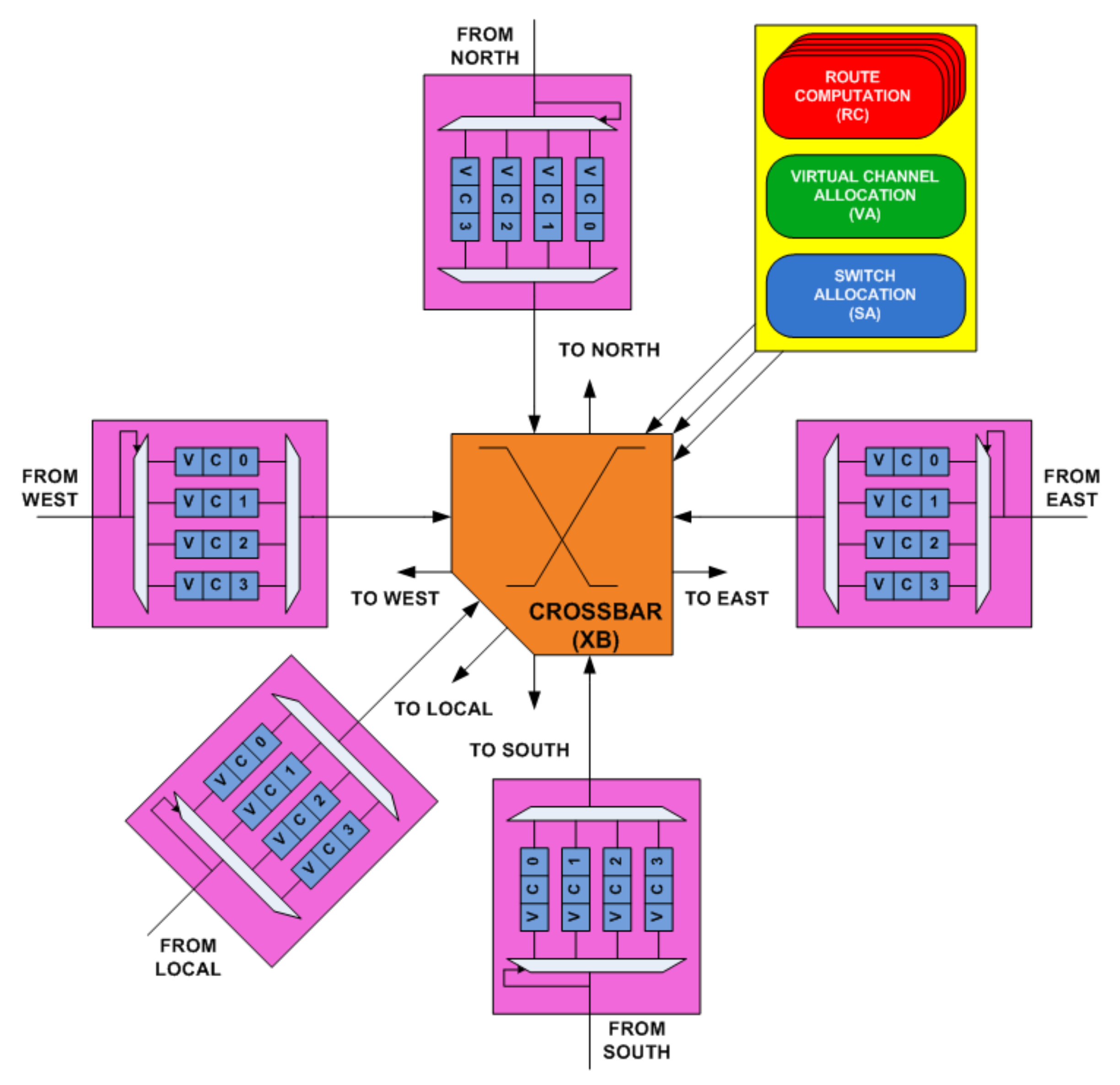
3. Generic NoC Router Architecture

Figure 1 shows the generic router architecture. It consists of five input/output ports. The data path of the router includes the input port and the XB unit. However, the control path includes the RC unit, VA unit, and SA unit [35]. RC, VA, SA & XB unit make up the four pipeline stages of the generic router. These pipeline stages facilitate packet traversal through the router.

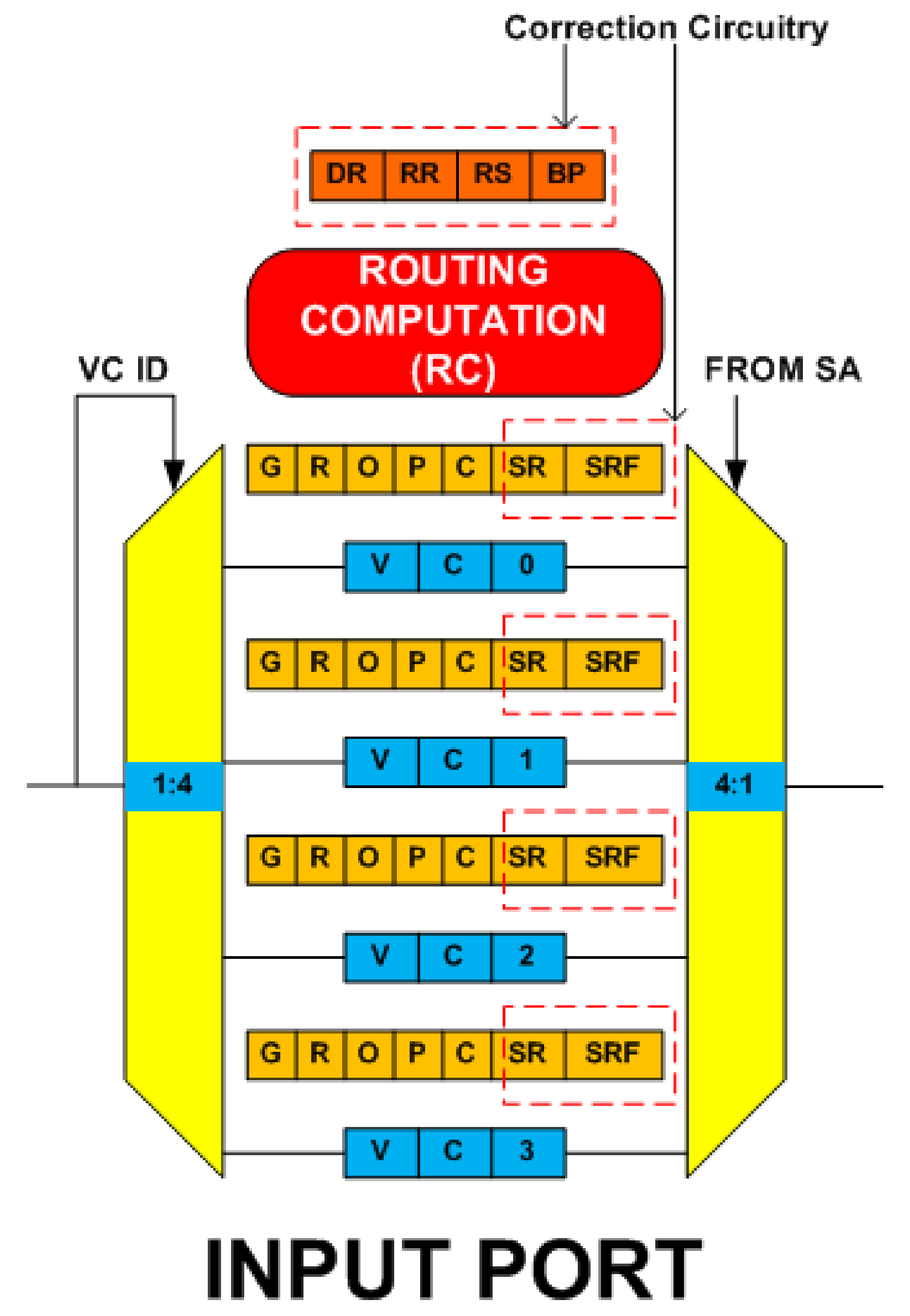
3.1. Overview of Router Input Port

Figure 2a shows the architecture of the input port of the router. Each input port consists of four VCs, a 4:1 multiplexer and a 1:4 demultiplexer. Status of each VC is maintained using a state field register. It has five status fields ‘G’, ‘R,’ ‘O,’ ‘P’ & ‘C.’ ‘G’ stores the global state of the VC. ‘R’ holds the result of the RC stage, i.e., output port identification for the packet. ‘O’ holds the assigned downstream VC identification as the result of the VA stage. ‘P’ contains the head and tail pointers for the flit in the VC buffer of the input port. ‘C’ holds the credits available for the downstream VC. They play an important role in flow control.

3.2. Overview of Pipeline Stages
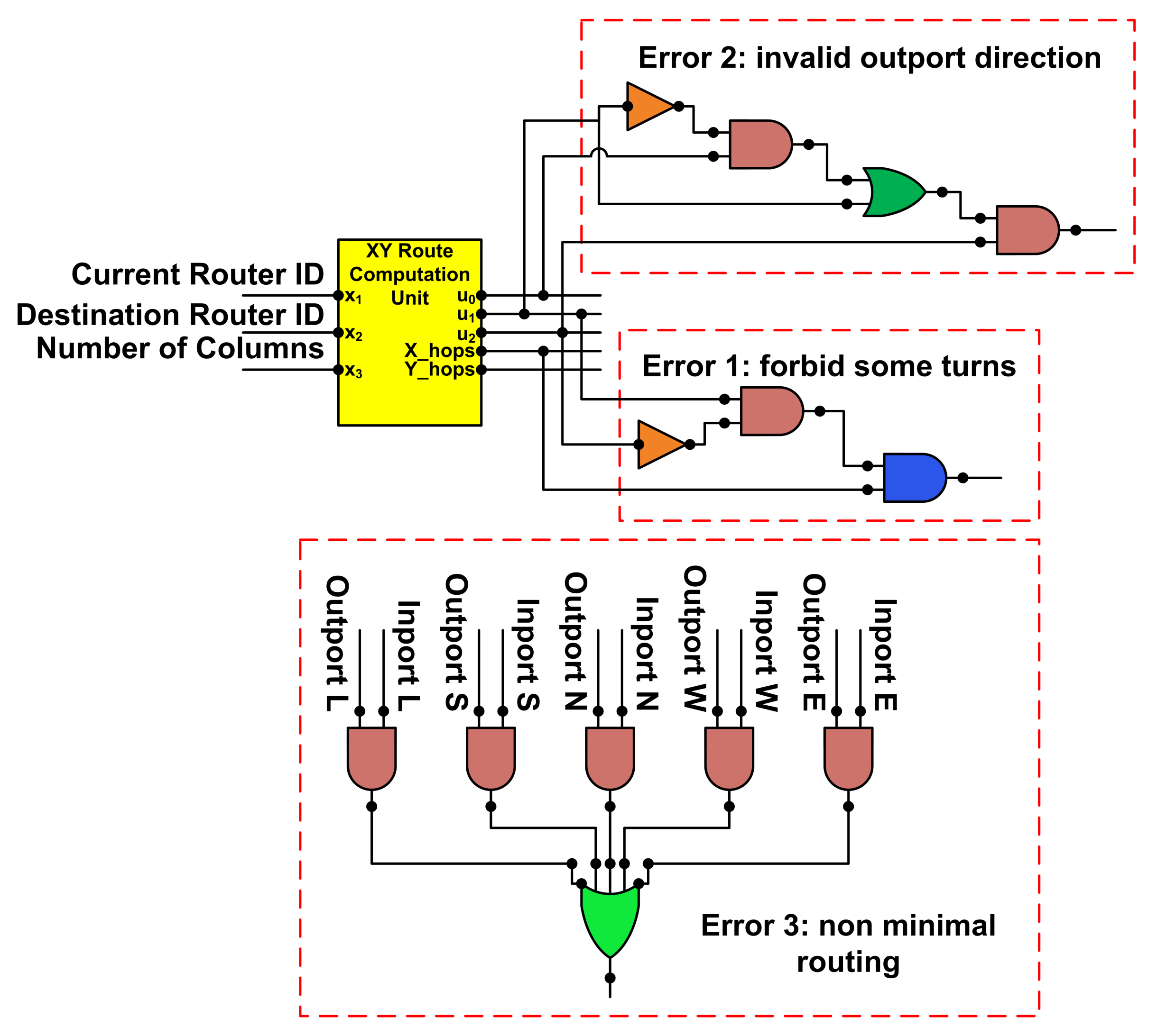
3.2.1. RC Stage

RC unit makes up the first stage in the router pipeline. It determines the output port for the packet on its arrival. The generic router employs a lookahead dimension order (XY) routing algorithm. Instead of computing the current output port, it calculates the output port for the downstream router at the current router. Head flit contains this pre-computed route. Thus, on the arrival of a packet, it goes directly into the VA stage. This stage triggers only on the arrival of the head flit and remains idle for the rest of the flits for that packet.

3.2.2. VA Stage

VA unit makes up the second stage in the router pipeline. It activates on the arrival of the head flit. Figure 2b [36] shows the two-stage separable VA. It consists of multiple arbiters. In the first stage, every input VC arbitrates for the empty VC at the downstream router based on the pre-computed route. In the second stage, the input VCs from different input ports that win arbitration for the same downstream VC in the first stage arbitrates with each other for that downstream VC. This stage remains idle for the rest of the flits for that packet.

3.2.3. SA Stage

SA unit makes up the third stage in the router pipeline. It operates on head, body and tail flits. It grants the flits in the VC access to the XB input ports. Figure 2c [36] shows the two-stage separable switch allocator. In the first stage, VCs from an input port arbitrate for getting access to the XB. In the second stage, it mediates among VCs from different input ports that are trying to reach the same input port of the XB. In a generic router, we use speculation, in which VA and SA stages execute at the same time. We use two separate SA units. The first SA unit handles the speculative requests for the packets that are also requesting a downstream VC in the VA stage. The second SA unit handles the non-speculative requests for the input VCs that win the VA stage but do not win speculative SA.

3.2.4. XB Stage

It is the last stage in the router pipeline. It operates on head, body and tail flits. It activates after the execution of the SA stage. The flit that wins arbitration in the SA stage now traverses through the XB and moves towards its destination. XB connects the input ports of the router to its output ports. Figure 2d shows the multiplexer-based crossbar. It consists of five 5:1 multiplexers. The SA unit generates control signals for the multiplexers. In every cycle, it configures the input and output port connections.

4. Effects of Fault on Router Pipeline

4.1. RC Stage Fault Scenario

If a fault occurs in the RC unit of an input port, it results in the wrong output port computation. Due to the lookahead routing protocol, this incorrect computation does not result in misrouting at the current router. Misrouting occurs in the downstream router only if the incorrect computation estimate is still a valid output port direction. In that case, the next downstream router directs the packet toward its correct destination. Thus, the packet incurs extra latency. If the incorrect computation is not a valid output port direction, then the packet sticks in the downstream router and end up causing deadlock. The downstream router may drop that packet which results in retransmission at the later stage.

4.2. VA Stage Fault Scenario

A fault in an arbiter of the VA stage results in miss-allocation or no-allocation of the downstream VC. In the case of the miss-allocation of the downstream VC, if the VC has been already occupied, then the latter packet overwrites the last one. It results in data corruption. In the case of no-allocation of the downstream VC, the packet does not proceed and remains in the buffer. It results in severe performance degradation and may end up as a deadlock.

4.3. SA Stage Fault Scenario

A fault in an arbiter of the first stage of SA, blocks the packets at the associated input port. Now the packet in each VC of that port does not proceed. A fault in an arbiter of the second stage of SA, makes the output port inaccessible. In both cases, the whole input port isolates permanently, causing severe degradation in performance and may lead to deadlock.

4.4. XB Stage Fault Scenario

A fault in a multiplexer of the XB results in an inaccessible output port. It severely disrupts the operation of the router. Adaptive routing or bypassing faulty multiplexers helps a router to operate in degradable manner.

5. NoCGuard Router Micro-Architecture

Each pipeline stage performs a specific function and has a distant role in the operation of the router. This work proposes a fault-tolerant design for each pipeline stage. For fault detection, NoCGuard relies on the NoCAlert fault detection mechanism [34].

5.1. RC Stage Fault-Tolerant Design

In the generic router, each input port has its own RC unit. There are five RC units per router. They operate on the head flit and remain idle for the body and tail flits. Knowing this fact, we propose to borrow the RC unit of adjacent ports when the RC unit of the current port become faulty. To facilitate the borrowing process, we propose four new state fields for each input port. Figure 3 shows the modified input port. It consists of the following new state fields: ‘DR’ (Destination Router), ‘RR’ (RC Result), ‘RS’ (RC Status) and ‘BP’ (Borrower Port).
Suppose a fault occurs in the RC unit of input port 1 (IP1). First, it changes the status of its RC unit to faulty in the ‘RS’ field register. Then it searches for an idle RC unit by checking the ‘RS’ field status of all other input ports. Suppose it finds the RC unit of input port 2 (IP2) idle. Now IP1 initiates the borrowing process by changing the status of ‘RS’ field of IP2 to active globally. Then IP1 stores the destination router identification of its packet in the ‘DR’ field and its input port identification in the ‘BP’ field register of IP2’s RC unit. After the route computation is complete, the IP2 RC unit places the route result in its ‘RR’ field register. In addition, changes the status of its ‘RS’ field back to idle. Now, IP1 accesses the ‘RR’ field register of IP2’s RC unit to get the RC result. ‘RS’ state field register takes four states namely idle, active locally (active for the current port), active globally (active for another port) and faulty. ‘BP’ state field register takes input port identification namely east, west, north, south and local.
We exploit the double routing strategy of [23] with the RC borrowing strategy. The generic router uses a lookahead routing mechanism. In which the RC unit of the upstream router computes the route for the next downstream router. In addition, embeds this pre-computed route in the packet and delivers it to the downstream router. The current router only computes the route for the next downstream router. Thus, we propose to skip the RC borrowing if we do not instantly get idle RC. Because if we are unable to find idle RC in the current cycle, we must wait for two or more cycles. Instead, we forward the packet to the downstream router based on the pre-computed route already present in the packet at the current router. Now the downstream router computes the current and next downstream router’s route using double routing strategy. It consumes one extra cycle. On the other hand, if an Idle RC was found instantly, the same one extra cycle was consumed. Thus, the use of both strategies gives high reliability as compared to the use of only double routing strategy as in RoCo [23] and HPR [29] router.
To detect faults in the RC unit, we use NoCAlert [34] invariance checkers. Figure 4 shows the fault detection circuitry. Error1 signal asserts on the illegal turn, forbidding, which is necessary to prevent deadlock in the network. Error2 signal asserts on the computation of invalid output port direction. Error3 signal detects whether the computed output port direction takes the flit one step closer to its destination or not.

5.2. VA Stage Fault-Tolerant Design

In the generic router, VA happens in two stages. We tolerate faults in the first stage at the second stage by using the default winner strategy. The second stage consists of twenty 20:1 arbiters, each of which associates with one downstream VC. The allocation requests to each 20:1 arbiter come from a set of arbiters in the first stage associated with each input port. Four requests come from an input port to a 20:1 arbiter. If faults occur in all corresponding four arbiters, we propose to provide one default winner request. In this way, VA proceeds even if all the arbiters in the first stage become faulty.
To facilitate fault tolerance at VA, we propose to add two registers per 20:1 arbiter as shown in Figure 5. The first register known as IDP (Identification of the Port) is 5-bit wide. Each bit of which represents the fault status of the first stage arbiter set of an input port. The corresponding bit is asserted if all four first stage arbiters of an input port become faulty. The second register, known as IDVC (Identification of the Virtual Channel), holds the identification of the default winner VC and is 10-bit wide. A pair of bits represents the identification of the default winner VC for the corresponding first stage arbiter set of an input port. On the occurrence of faults, the corresponding fault status bit asserts. Now the 20:1 arbiter takes input from the corresponding default winner register instead of first stage arbiters. In this way, even if all first stage arbiters are faulty, VA proceeds by using the default winner strategy. This strategy consumes no extra cycle, as it does not depend on time upon any other computation.
The success of the default winner scheme is highly dependent on the selection methodology for the default winner. Poor selection methodology results in starvation. Arbiters in the generic router use round-robin selection methodology. The selection fairness should be close to the fairness of the round-robin arbiter. We propose the selection based on the R and C field of the VC status register. In addition, default winner rotates in a cyclic manner to provide fairness. It avoids static allocation, which can cause starvation. In this way, packet in every VC gets a chance to proceed.
Both VA and SA stages consist of arbiters. Figure 6 shows the NoCAlert [34] invariance checkers for arbiters. Error1 signal asserts if arbiter grants without getting any request. Error2 signal asserts if arbiter does not grant on requests. Error3 signal asserts, if more than one bit of a grant vector is logically high, i.e., an arbiter gives multiple grants at a time.

5.3. SA Stage Fault-Tolerant Design

The generic router consists of two identical sets of SA units. One unit handles the speculative requests, and the second unit handles the non-speculative requests. On the arrival of the flit, it directly requests for speculative SA. Upon allocation, if the flit has already won the VA stage, it goes for the XB stage. Otherwise, in the next cycle, it requests for non-speculative SA. We exploit this redundancy to achieve fault tolerance. Non-speculative SA unit is more critical than the speculative one because if a fault occurs in it, an input port will not win a non-speculative grant and SA will not proceed.
Figure 7 shows the proposed fault-tolerant SA design. It is the modification of the runtime arbiter selection strategy for fault tolerance proposed in [29]. By exploiting the inherent redundancy provided by speculation, [29] proposes to select the arbiters of both allocators at runtime. It ensures that the non-speculative requests will never be blocked, and SA always proceeds. To do that, it shifts the non-speculative requests to the speculative arbiter at runtime, if the corresponding non-speculative arbiter becomes faulty. It achieves that by adding a few 2:1 multiplexers to select between appropriate arbiters. Subsequent speculative requests at that time shift to the non-speculative arbiter. As non-speculative arbiter is already faulty, the flit uses the speculative arbiter in the next cycle. This strategy works both for the first and second stages of SA. Arbiter fault detection mechanism generates necessary control signals for runtime arbiter selection multiplexers. In case of a fault, this strategy consumes an extra cycle.
Now the speculative SA of the first stage becomes critical, handling both types of requests. To protect it, we propose a default winner strategy. When the arbiter of the speculative SA of the first stage becomes faulty, the input VC identification stored in the register is considered to be the winner without arbitration. The choice of the default winner is very critical. If a specific input VC is always a default winner, it causes static allocation and results in starvation. To avoid this, we purpose dynamic allocation in which VC identification in the register rotates. The identification of the first non-empty VC found in an input port is stored in the register. Once all the flits in that VC have successfully traversed the XB, the register is updated with the next non-empty VC. This is how starvation is avoided by rotating VCs as a default winner. To further enhance reliability, this strategy is also used for the first stage of non-speculative SA. Default winner strategy does not consume an extra cycle because it does not depend on time upon any other component. The default winner strategy kicks in when corresponding arbiters in speculative and non-speculative SA become faulty. It not only saves an extra cycle but also proceeds SA. Thus, the use of both strategies gives high reliability as compared to the HPR router [29].

5.4. XB Stage Fault-Tolerant Design

In the multiplexer-based XB, each output port associated with a multiplexer. Exactly one primary path exists to access an output port. The flit traverses the multiplexer to reach its output port. A fault in the multiplexer blocks all the flits trying to access that output port. We modify the XB to add multiple secondary paths to bypass the faulty multiplexer. The flits use the secondary bypass paths to access an output port. Secondary bypass paths consist of small size multiplexers. Figure 8 shows the XB fault-tolerant architecture.
For example, from Figure 8 consider an output port (out1). Multiplexers (M1, N1, O1) form the primary path to access out1. When a fault occurs in the primary multiplexer M1, out1 becomes inaccessible. In this case, the flit uses a secondary bypass path to reach out1. The following sets of multiplexer combinations form secondary bypass paths to reach out1: (M2, N1, O1), (M3, N3, 01), (M4, N3, 01). The SA provides necessary control signals for the additional multiplexers. The secondary bypass paths are only used in case of fault. In the absence of fault, secondary bypass paths are inactive, and the architecture behaves like generic 5 × 5 XB.
To use the secondary bypass path, flit uses the primary multiplexer of another output port. The input port VC containing that flit must arbitrate for this output port in its SA stage. For the above example, when M1 is faulty, the flit must go through M2, M3, or M4 to reach out1. To facilitate this, we add two new state fields to the status register of each input VC (shown in Figure 3). First is the secondary route field ‘SR’, it holds the output port associated with the primary multiplexer of the secondary bypass path. Second is the secondary route flag field ‘SRF’, it indicates the fault status of the primary multiplexer.
In case of a fault, after route computation the SR field is updated with the appropriate output port. For the above example, the ‘SR’ field is updated with one of the output port associated with multiplexers (M2, M3 & M4). Then the secondary route flag ‘SRF’ is raised to indicate that there is a fault in the primary multiplexer, so the secondary bypass path is to be used. This strategy also helps in the fault tolerance for the second stage of SA. By arbitrating for another output port and using a secondary bypass path, faults in the arbiter of the second stage of the SA are tolerated.

6. Performance Analysis

Hardware Overhead Analysis

We developed the generic and the NoCGuard router in Verilog HDL. Each router consists of five input and output ports. Each input port consists of four VCs. For the synthesis of both designs, we use the NangateOpenCell 15 nm [37] and 45 nm library with the Cadence Genus Synthesis Solution. Synthesis results reveal that our fault-tolerant design incurs an area overhead of 28.7% for 15 nm and 28% for 45 nm technology node.

7. Reliability Analysis

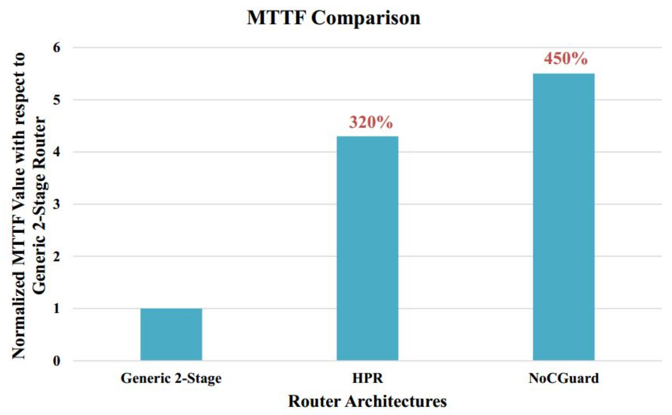
7.1. Mean Time to Failure (MTTF) Analysis

To estimate the reliability improvement of the NoCGuard router as compared to the generic router, we use MTTF [38] metric. MTTF of a component is given as
M T T F c o m p o n e n t = 1 F I T c o m p o n e n t
where FIT c o m p o n e n t (failure in time) is the number of failures occurring in a billion hours of operation.

7.1.1. Failures in Time (FIT) Estimation Model

For FIT estimation, we employ the modeling framework for the architectural level lifetime reliability of [39]. It provides a mathematical model for the estimation of the FIT rate of the circuit. It considers three failure mechanisms, i.e., TDDB, EM, and NBTI for reliability modeling. The effects of EM and NBTI can be suppressed by decreasing stress on the circuit. TDDB results in an electrical breakdown of the gate oxide. There is no recovery mechanism for TDDB. TDDB causes prolong charge transport through gate oxide [40]. This charge leakage through the gate oxide affects the logic state transition, making the device susceptible to timing violations. Thus, being the prominent cause of permanent faults, we only calculate MTTF for TDDB induced failures. This reliability modeling framework proposes failure in time of reference circuit (FORC) for FIT c o m p o n e n t estimation. Without dealing with the technological and low-level circuit implementation, it enables the designer to quantify failure rates of a component. FORC for either pFET or nFET effected by TDDB mechanism is given by [39],
F O R C T D D B = 10 9 A T D D B × V d d a b T × e x + y T + z T k T
where A TDDB , a, b, X, Y & Z represent the fitting parameters. [41] provides their experimental values. K represents the Boltzmann constant. V dd represents the circuit voltage taken 1V. T represents the ambient temperature taken 300 K. Using FORC TDDB the FIT for a FET (either p or n-type) is given as
F O R C T D D B _ p e r _ F E T = d u t y c y c l e × F O R C T D D B
Assuming continuous stress on the device, i.e., 100% duty cycle. If the number of transistors in a logic gate are given, then the F I T c o m p o n e n t is calculated as
F I T c o m p o n e n t = n u m b e r _ o f _ t r a n s i s t o r s l o g i c _ g a t e × F I T T D D B _ p e r _ F E T
The sum of failure rates (SOFR) model is used to estimate the FIT rates for a logic circuit [42]. According to the SOFR model, the FIT rate of a logic circuit is equal to be the sum of the FIT rates of the individual gates of that circuit. As an example, the FIT rate of the logic circuit comprised of basic logic gates AND, OR, NOT and XOR is calculated by taking the sum of the FIT rates of the individual gates. By using the above methodology, we estimate the FIT rates for the components of the generic router pipeline stages and the correction circuitry of the NoCGuard router.

7.1.2. FIT Rate of Generic 2-Stage NoC Router

The generic NoC router consists of five input/output ports and four VCs per input port. A comparator is the basic building block of the RC stage. The RC stage uses the dimension order XY routing algorithm in 8 × 8 mesh topology. Thus, it requires one comparator for X dimension and one for the Y dimension. In 8 × 8 mesh topology, there are 64 routers. 6-bits are needed to represent the identification of 64 routers (26 = 64). Thus, the RC stage requires a 6-bit comparator. An arbiter is the basic building block of the VA stage. It uses 4:1 arbiters in the first stage and 20:1 arbiters in the second stage. Arbiter and multiplexer are the basic building blocks of the SA stage. It employs 4:1 arbiters and 4:1 multiplexers in the first stage and 5:1 arbiters in the second stage. The multiplexer is the basic building block of the XB. It employs 32-bit 5:1 multiplexers.
Table 1 lists the components of the generic router and the number in which they are present in each pipeline stage. It also shows the FIT rates for each component and the overall FIT rates of the whole pipeline stage based on the SOFR model.

7.1.3. FIT Rate of Correction Circuitry

  • RC Pipeline Stage
    This stage uses the resource borrowing and the double routing strategy for fault tolerance. Correction circuitry consists of four new state fields namely ‘DR’, ‘RR’, ‘RS, and ‘BP’. Implementation requires 6-bit D flip-flop (DFF) for ‘DR’, 3-bit DFF for ‘RR’, 2-bit DFF for ‘RS’ and 3-bit DFF for the ‘BP’ field. The double routing strategy does not incur any correction circuitry.
  • VA Pipeline Stage
    This stage uses the default winner strategy for fault tolerance. Correction circuitry consists of two new state fields namely ‘IDP’ and ‘IDVC’. Implementation requires 5-bit DFF for the ‘IDP’ and 10-bit DFF for the ‘IDVC’ field.
  • SA Pipeline Stage
    This stage uses the runtime arbiter selection and the default winner strategy for fault tolerance. Correction circuity for the runtime arbiter selection strategy consists of 2:1 multiplexers. Correction circuity for the default winner strategy consists of 2:1 multiplexers and 2-bit DFF registers (reg). SA stage also facilitates the fault tolerance in the XB stage. For that, it adds two new state fields, namely ‘SR’ and ‘SRF’ to each input VC. Implementation requires 3-bit DFF for the ‘SR’ and 1-bit DFF for the ‘SRF’ field.
  • XB Pipeline Stage
    This stage uses the multiple secondary bypass paths strategy for fault tolerance. Correction circuitry consists of 32-bit 2:1 multiplexers.
Table 2 lists the components of the correction circuitry and the number in which they are present in each pipeline stage. It also shows the FIT rates for each component and the overall FIT rates of the whole pipeline stage correction circuitry based on the SOFR model.

7.1.4. MTTF Estimation of NoCGuard Router

By using the SOFR model, the MTTF of the generic router is given as
M T T F g e n e r i c _ r o u t e r = 1 F I T R C + F I T V A + F I T S A + F I T X B
Putting FIT values for the components of the generic router from Table 1,
M T T F g e n e r i c _ r o u t e r = 10 9 117 + 1474 + 215 + 1024 353356.89 h o u r s
NoCGuard router modifies the generic router for fault tolerance by adding the correction circuitry. MTTF of the system with two components (i.e., the generic router and the correction circuitry) with failure rates FIT 1 and FIT 2 is given as
M T T F N o C G u a r d _ r o u t e r = 1 F I T 1 + 1 F I T 2 + 1 F I T 1 + F I T 2
FIT 1 is the sum of the failure rates of each pipeline stage of the generic router. By using Table 1, it is calculated as
F I T 1 = 117 + 1474 + 215 + 1024 = 2830
FIT 2 is the sum of the failure rates of the correction circuitry for each pipeline stage. By using Table 2, it is calculated as
F I T 2 = 35 + 150 + 98 + 470.7 = 753.7
Now by putting the values of FIT 1 and FIT 2 from Equations (8) and (9) into Equation (7), MTTF of the NoCGuard router is given as
M T T F N o C G u a r d _ r o u t e r = 10 9 2830 + 10 9 753.7 + 10 9 2830 + 753.7 1959185.95 h o u r s
The reliability improvement is the ratio of the MTTF of the NoCGuard router to the MTTF of the generic router. By using Equations (6) and (10), reliability improvement is calculated as
M T T F N o C G u a r d _ r o u t e r M T T F g e n e r i c _ r o u t e r = 1959185.95 353356.89 5.5
Hence, the proposed NoCGuard router is 5.5 times more reliable than the generic router. Figure 9 shows the MTTF comparison of the NoCGuard router with the generic NoC router and state-of-the-art reliable HPR router [29]. HPR router is 4.3 times more reliable than the generic router. MTTF of the NoCGuard router increases by 450% compared to the generic router. However, the MTTF of the HPR router increases by 320% compared to the respective generic router. Hence, NoCGuard is more reliable than the state-of-the-art HPR reliable router [29].

7.2. Mean Defects to Failure (MDTF) Analysis

To estimate the reliability improvement of the NoCGuard router as compared to the existing reliable routers, we use the MDTF metric. MDTF of a system is given as
M D T F = M a x i m u m f a u l t s t o c a u s e f a i l u r e + M i n i m u m f a u l t s t o c a u s e f a i l u r e 2

7.2.1. Fault Estimation of Pipeline Stages

To calculate the MDTF of the NoCGuard router, we first calculate the maximum and the minimum number of faults each pipeline stage tolerates.
  • RC Pipeline Stage
    This stage uses the resource borrowing and the double routing strategy for fault tolerance. If all five RC units of a current router and four RC units of adjacent router become faulty, the router still works due to borrowing and double routing strategy. Therefore, the router tolerates a maximum of 9 faults. On the other hand, if all five RC units of the adjacent router become faulty then it does not compute current as well as lookahead route. Therefore, a minimum of 5 faults causes RC failure.
  • VA Pipeline Stage
    This stage uses the default winner strategy for fault tolerance. It tolerates faults in the arbiters of the first stage by providing their default winner at the second stage of the VA. If all twenty-first stage arbiters at an input port become faulty, then VA proceeds by using their default winner at corresponding twenty-second stage arbiters. Therefore, the router can tolerate the maximum 20 faults. There are four VCs per port. For every output port VC, there is one arbiter in the second stage of the VA. If all four arbiters associated with an output port become faulty, the output port becomes inaccessible. Therefore, a minimum of 4 faults causes VA failure.
  • SA Pipeline Stage
    This stage uses the runtime arbiter selection and the default winner strategy for fault tolerance. If all ten arbiters of the non-speculative set and ten arbiters of the speculative set become faulty, then SA proceeds using the default winner strategy. Thus, the router tolerates a maximum of 20 faults. If for an input port, a speculative and a non-speculative arbiter, along with their default winner registers become faulty, SA fails. Therefore, a minimum of 4 faults causes SA failure.
  • XB Pipeline Stage
    This stage uses the multiple bypass paths strategy for fault tolerance. A fault in the primary multiplexer associated with an output port makes it unreachable. We provide three secondary bypass paths to access an output port. For local output port, four secondary paths are present, and its primary multiplexer does not take part in making secondary paths for any other output port. Hence, it is not considered in this calculation. Therefore, the router tolerates a maximum 3 faults. If all four primary multiplexers become faulty, output ports become unreachable. Therefore, a minimum of 4 faults causes XB failure.

7.2.2. MDTF Estimation of NoCGuard Router

To calculate MDTF, take the mean of the minimum and the maximum number of faults to cause router failure. The minimum number of faults to cause router failure is the least number of faults among the minimum number of faults to cause the failure of any pipeline stage. Because if a pipeline stage fails, the operation of the whole router fails. Based on the above analysis, the minimum number of faults to cause NoCGuard router failure is calculated as
m i n [ 5 , 4 , 4 , 4 ] = 4 f a u l t s
Thus, a minimum of 4 faults in a pipeline stage cause failure of the NoCGuard router.
The maximum number of faults the router tolerates is the sum of the maximum number of faults each pipeline stage tolerates. Based on the above analysis, the maximum number of faults NoCGuard router tolerates is calculated as
s u m [ 9 , 20 , 20 , 3 ] = 52 f a u l t s
Thus, the NoCGuard router tolerates a maximum 52 faults. To calculate MDTF, we need a maximum number of faults to cause router failure. The router will fail on the occurrence of one more fault than the maximum number of faults the router tolerates. Thus, for the NoCGuard router, the maximum number of faults to cause failure are 52 + 1 = 53. Now by putting these values in Equation (12), the MDTF of NoCGuard router is calculated as:
M D T F = 4 + 53 2 = 28.5
Thus, on average 28.5 faults cause the failure of the NoCGuard router. We compare MDTF of our NoCGuard router with the existing reliable routers such as BulletProof [22], RoCo [23], Vicis [24], PVS [26], REPAIR [25], SHIELD [28], DRS [27] and HPR [29]. From Figure 10, it is evident that the MDTF of NoCGuard is greater than the existing reliable router architectures.

7.3. SPF Analysis

To estimate the reliability improvement of the NoCGuard router as compared to the generic router, we use SPF [22] as a figure of merit. It considers the fault-tolerant capability of the architecture with respect to the hardware cost. It is given as
S P F = M D T F A r e a o f f a u l t t o l e r a n t r o u t e r A r e a o f g e n e r i c r o u t e r
By using MDTF and area overhead, Equation (17) gives
S P F = 28.5 1.28 = 22.26
Table 3 shows the SPF comparison of NoCGuard router with state-of-the-art reliable router architectures. It is evident that the proposed architecture is more economical than the existing reliable router architectures.

8. Latency Analysis

In this section, we discuss the impact of fault-tolerant enhancements on the latency of a generic router. Gem5 [43] simulator is used for simulation. The generic router is simulated in Garnet [44]. It is then modified to implement NoCGuard fault-tolerant design.
For software-based fault simulations, the ideal way is to inject faults based on the failure rates of pipeline components. Failure rates estimated in the previous section are minimal. For these failure rates, the simulation runs for a very long time. To reduce simulation time, a fault is injected after 1 million cycles. All simulations are done on an 8 × 8 mesh network and executed for 10 million cycles. In 8 × 8 mesh, there are 64 nodes, i.e., routers. We inject faults at 20 randomly chosen routers. Each router is injected with a fault in two of its pipeline stages. Different pipeline stages of a router are chosen randomly for fault injection. Two experiments are conducted. First using synthetic traffic and second using PARSEC [45] and SPLASH-2 [46] benchmark applications.
The first experiment with synthetic traffic employs uniform random, tornado, shuffle and transpose traffic patterns. Injection rate varies from 0.01 to 0.1 packets/node/cycle in 5 steps. Figure 11 shows the latency comparison of NoCGuard and HPR [29] router with the generic router under synthetic traffic patterns. In the absence of faults, NoCGuard incurs no extra latency. For uniform random, tornado, shuffle and transpose traffic patterns, the average increase in latency is 3.45%, 3.41%, 3.46% and 3.32% respectively. This increase in average latency is less for all traffic patterns than the state-of-the-art HPR reliable router architecture.
The second experiment employs PARSEC and SPLASH-2 benchmark applications. In 8x8 mesh each core associates with a cache and directory. The NoC uses MOESI_CMP_directory cache coherence protocol in this experiment. Figure 12 and Figure 13 shows the latency comparison of NoCGuard and HPR [29] router with the generic router under PARSEC and SPLASH-2 benchmark applications. NoCGuard incurs no extra latency in the absence of faults. For PARSEC and SPLASH-2 benchmark applications the average increase in latency is 12% and 15% respectively. For benchmark applications too, the increase in average latency is less for all application traces than the state-of-the-art HPR [29] reliable router architecture.

9. Conclusions

We propose NoCGuard, a gracefully degraded in performance and reliable router architecture based on a generic router. It uses different architectural modifications to tolerate faults on routers RC, VA, SA and XB pipeline stages. Simulation results show graceful degradation in latency even under heavy network traffic. Lifetime reliability evaluation using MTTF reveals 5.53 times improvement as compared to a state-of-the-art reliable router architecture. Most importantly, the mean no. of faults to cause failure, area, and SPF estimation show that NoCGuard is more reliable than existing state-of-the-art reliable router architectures. Overall, NoCGuard achieves the right balance between performance degradation, reliability, and area overhead incurred.

Author Contributions

Conceptualization, M.A.S. and N.K.B.; methodology, M.A.S. and N.K.B.; software, M.A.S. and N.K.B.; validation, M.A.S., N.K.B., M.I.B. and F.H.; writing—original draft preparation, M.A.S., N.K.B., M.I.B. and F.H.; writing—review and editing, Y.B.Z. and S.W.K; visualization, M.A.S. and N.K.B.; supervision, N.K.B., Y.B.Z. and S.W.K.; project administration, N.K.B. and M.I.B. All authors have read and agreed to the published version of the manuscript.

Acknowledgments

This research was supported in part by the Brain Korea 21 Plus Program (No. 22A20130012814) funded by the National Research Foundation of Korea (NRF), in part by the MSIT(Ministry of Science and ICT), Korea, under the ITRC(Information Technology Research Center) support program(IITP-2019-2016-0-00313) supervised by the IITP(Institute for Information & communications Technology Planning & Evaluation), and in part by Basic Science Research Program through the National Research Foundation of Korea (NRF) funded by the Ministry of Education (2018R1D1A1A09082266) and in part by University of Engineering & Technology, Taxila, Pakistan).

Conflicts of Interest

The authors declare no conflict of interest.

References

  1. ITRS. International Technology Roadmap for Semiconductors; Technical Report; ITRS: Hong Kong, China, 2011. [Google Scholar]
  2. Borkar, S. Thousand Core Chips: A Technology Perspective. In Proceedings of the 44th Annual Design Automation Conference, San Diego, CA, USA, 4 June 2007; pp. 746–749. [Google Scholar] [CrossRef]
  3. Dally, W.J.; Towles, B. Route packets, not wires: On-chip interconnection networks. In Proceedings of the 38th Design Automation Conference (IEEE Cat. No.01CH37232), Las Vegas, NV, USA, 23 May 2001; pp. 684–689. [Google Scholar] [CrossRef]
  4. Benini, L.; De Micheli, G. Networks on chips: A new SoC paradigm. Computer 2002, 35, 70–78. [Google Scholar] [CrossRef] [Green Version]
  5. Salminen, E.; Kulmala, A.; Hamalainen, T.D. On network-on-chip comparison. In Proceedings of the 10th Euromicro Conference on Digital System Design Architectures, Methods and Tools (DSD 2007), Lubeck, Germany, 31 August 2007; pp. 503–510. [Google Scholar] [CrossRef]
  6. Borkar, S. Design challenges of technology scaling. IEEE Micro 1999, 19, 23–29. [Google Scholar] [CrossRef]
  7. Borkar, S. Designing reliable systems from unreliable components: The challenges of transistor variability and degradation. IEEE Micro 2005, 25, 10–16. [Google Scholar] [CrossRef]
  8. Radetzki, M.; Feng, C.; Zhao, X.; Jantsch, A. Methods for Fault Tolerance in Networks-on-chip. ACM Comput. Surv. 2013, 46, 1–38. [Google Scholar] [CrossRef]
  9. Oussalah, S.; Nebel, F. On the oxide thickness dependence of the time-dependent-dielectric-breakdown. In Proceedings of the 1999 IEEE Hong Kong Electron Devices Meeting (Cat. No.99TH8458), Hong Kong, China, 26 June 1999; pp. 42–45. [Google Scholar] [CrossRef]
  10. Barsky, R.; Wagner, I.A. Electromigration-dependent parametric yield estimation. In Proceedings of the 2004 11th IEEE International Conference on Electronics, Circuits and Systems, Tel Aviv, Israel, 13 December 2004; pp. 121–124. [Google Scholar] [CrossRef]
  11. Mahapatra, S.; Bharath Kumar, P.; Dalei, T.R.; Sana, D.; Alam, M.A. Mechanism of negative bias temperature instability in CMOS devices: Degradation, recovery and impact of nitrogen. IEDM Technical Digest. IEEE Int. Electron Devices Meet. 2004, 2004, 105–108. [Google Scholar] [CrossRef] [Green Version]
  12. Groeseneken, G.V. Hot carrier degradation and ESD in submicrometer CMOS technologies: How do they interact? IEEE Trans. Device Mater. Reliab. 2001, 1, 23–32. [Google Scholar] [CrossRef]
  13. JEDEC. Failure Mechanisms and Models for Semiconductor Devices; Technical Report; JEDEC: Arlington, VA, USA, 2009. [Google Scholar]
  14. Kuhn, K.J. Reducing Variation in Advanced Logic Technologies: Approaches to Process and Design for Manufacturability of Nanoscale CMOS. In Proceedings of the 2007 IEEE International Electron Devices Meeting, Washington, DC, USA, 10 December 2007; pp. 471–474. [Google Scholar] [CrossRef]
  15. May, T.C.; Woods, M.H. Alpha-particle-induced soft errors in dynamic memories. IEEE Trans. Electron Devices 1979, 26, 2–9. [Google Scholar] [CrossRef]
  16. Sai-Halasz, G.A.; Wordeman, M.R.; Dennard, R.H. Alpha-Particle-Induced Soft Error Rate in VLSI Circuits. IEEE J. Solid-State Circuits 1982, 17, 355–361. [Google Scholar] [CrossRef]
  17. Ziegler, J.F. Terrestrial cosmic ray intensities. IBM J. Res. Dev. 1998, 42, 117–140. [Google Scholar] [CrossRef]
  18. Werner, S.; Navaridas, J.; Luján, M. A Survey on Design Approaches to Circumvent Permanent Faults in Networks-on-Chip. ACM Comput. Surv. 2016, 48, 1–36. [Google Scholar] [CrossRef]
  19. Ibrahim, M.; Baloch, N.K.; Anjum, S.; Zikria, Y.B.; Kim, S.W. An Energy Efficient and Low Overhead Fault Mitigation Technique for Internet of Thing Edge Devices Reliable On-Chip Communication. Software: Practice and Experience. Available online: https://onlinelibrary.wiley.com/doi/pdf/10.1002/spe.2796 (accessed on 16 February 2020).
  20. Feng, C.; Lu, Z.; Jantsch, A.; Zhang, M.; Xing, Z. Addressing Transient and Permanent Faults in NoC With Efficient Fault-Tolerant Deflection Router. IEEE Trans. Very Large Scale Integr. Syst. 2013, 21, 1053–1066. [Google Scholar] [CrossRef] [Green Version]
  21. Ebrahimi, M.; Wang, J.; Huang, L.; Daneshtalab, M.; Jantsch, A. Rescuing healthy cores against disabled routers. In Proceedings of the 2014 IEEE International Symposium on Defect and Fault Tolerance in VLSI and Nanotechnology Systems (DFT), Amsterdam, The Netherlands, 1 October 2014; pp. 98–103. [Google Scholar] [CrossRef]
  22. Constantinides, K.; Plaza, S.; Blome, J.; Zhang, B.; Bertacco, V.; Mahlke, S.; Austin, T.; Orshansky, M. BulletProof: A defect-tolerant CMP switch architecture. In Proceedings of the Twelfth International Symposium on High-Performance Computer Architecture, Austin, TX, USA, 11 February 2006; pp. 5–16. [Google Scholar] [CrossRef] [Green Version]
  23. Das, C.R.; Yousif, M.S.; Narayanan, V.; Dongkook, P.; Nicopoulos, C.; Jongman, K.; Das, C.R.; Yousif, M.S.; Narayanan, V.; Dongkook, P.; et al. A Gracefully Degrading and Energy-Efficient Modular Router Architecture for On-Chip Networks. In Proceedings of the 33rd International Symposium on Computer Architecture (ISCA’06), Boston, MA, USA, 17 June 2006; pp. 4–15. [Google Scholar] [CrossRef]
  24. Fick, D.; DeOrio, A.; Jin, H.; Bertacco, V.; Blaauw, D.; Sylvester, D. Vicis: A reliable network for unreliable silicon. In Proceedings of the 2009 46th ACM/IEEE Design Automation Conference, San Francisco, CA, USA, 26 July 2009; pp. 812–817. [Google Scholar] [CrossRef]
  25. Xie, L.; Mei, K.; Li, Y. REPAIR: A Reliable Partial-Redundancy-Based Router in NoC. In Proceedings of the 2013 IEEE Eighth International Conference on Networking, Architecture and Storage, Xian, Shaanxi, China, 17 July 2013; pp. 173–177. [Google Scholar] [CrossRef]
  26. Latif, K.; Rahmani, A.M.; Nigussie, E.; Seceleanu, T.; Radetzki, M.; Tenhunen, H. Partial Virtual Channel Sharing: A Generic Methodology to Enhance Resource Management and Fault Tolerance in Networks-on-Chip. J. Electron. Test. 2013, 29, 431–452. [Google Scholar] [CrossRef]
  27. Valinataj, M.; Shahiri, M. A low-cost, fault-tolerant and high-performance router architecture for on-chip networks. Microprocess. Microsyst. 2016, 45, 151–163. [Google Scholar] [CrossRef]
  28. Poluri, P.; Louri, A. Shield: A Reliable Network-on-Chip Router Architecture for Chip Multiprocessors. IEEE Trans. Parallel Distrib. Syst. 2016, 27, 3058–3070. [Google Scholar] [CrossRef]
  29. Wang, L.; Ma, S.; Li, C.; Chen, W.; Wang, Z. A high performance reliable NoC router. Integration 2017, 58, 583–592. [Google Scholar] [CrossRef]
  30. Mohammed, H.J.; Flayyih, W.N.; Rokhani, F.Z. Tolerating Permanent Faults in the Input Port of the Network on Chip Router. J. Low Power Electron. Appl. 2019, 9. [Google Scholar] [CrossRef] [Green Version]
  31. Putkaradze, T.; Azad, S.P.; Niazmand, B.; Raik, J.; Jervan, G. Fault-resilient NoC router with transparent resource allocation. In Proceedings of the 2017 12th International Symposium on Reconfigurable Communication-centric Systems-on-Chip (ReCoSoC), Madrid, Spain, 31 March 2017; pp. 1–8. [Google Scholar] [CrossRef]
  32. Li, C.; Yang, M.; Ampadu, P. An Energy-Efficient NoC Router with Adaptive Fault-Tolerance Using Channel Slicing and On-Demand TMR. IEEE Trans. Emerg. Top. Comput. 2018, 6, 538–550. [Google Scholar] [CrossRef]
  33. Wang, J.; Ebrahimi, M.; Huang, L.; Xie, X.; Li, Q.; Li, G.; Jantsch, A. Efficient Design-for-Test Approach for Networks-on-Chip. IEEE Trans. Comput. 2019, 68, 198–213. [Google Scholar] [CrossRef]
  34. Prodromou, A.; Panteli, A.; Nicopoulos, C.; Sazeides, Y. NoCAlert: An On-Line and Real-Time Fault Detection Mechanism for Network-on-Chip Architectures. In Proceedings of the 2012 45th Annual IEEE/ACM International Symposium on Microarchitecture, Vancouver, BC, Canada, 1 December 2012; pp. 60–71. [Google Scholar] [CrossRef]
  35. Dally, W.; Towles, B. Principles and Practices of Interconnection Networks; Morgan Kaufmann Publishers Inc.: San Francisco, CA, USA, 2003. [Google Scholar]
  36. Peh, L.; Dally, W.J. A delay model and speculative architecture for pipelined routers. In Proceedings of the HPCA Seventh International Symposium on High-Performance Computer Architecture, Monterrey, Nuevo Leon, Mexico, 19 January 2001; pp. 255–266. [Google Scholar] [CrossRef]
  37. Martins, M.; Matos, J.M.; Ribas, R.P.; Reis, A.; Schlinker, G.; Rech, L.; Michelsen, J. Open Cell Library in 15 nm FreePDK Technology. In Proceedings of the 2015 Symposium on International Symposium on Physical Design, Monterey, CA, USA, 29 March 2015; pp. 171–178. [Google Scholar] [CrossRef]
  38. Gaver, D.P. Time to Failure and Availability of Paralleled Systems with Repair. IEEE Trans. Reliab. 1963, R-12, 30–38. [Google Scholar] [CrossRef]
  39. Shin, J.; Zyuban, V.; Hu, Z.; Rivers, J.A.; Bose, P. A Framework for Architecture-Level Lifetime Reliability Modeling. In Proceedings of the 37th Annual IEEE/IFIP International Conference on Dependable Systems and Networks (DSN’07), Edinburgh, UK, 25 June 2007; pp. 534–543. [Google Scholar] [CrossRef]
  40. Wu, E.Y.; Nowak, E.J.; Vayshenker, A.; Lai, W.L.; Harmon, D.L. CMOS scaling beyond the 100-nm node with silicon-dioxide-based gate dielectrics. IBM J. Res. Dev. 2002, 46, 287–298. [Google Scholar] [CrossRef]
  41. Srinivasan, J.; Adve, S.V.; Bose, P.; Rivers, J.A. The case for lifetime reliability-aware microprocessors. In Proceedings of the 31st Annual International Symposium on Computer Architecture, Munchen, Germany, 23 June 2004; pp. 276–287. [Google Scholar] [CrossRef]
  42. Kouvatsos, D.D. Probability Statistics with Reliability, Queueing and Computer Science Applications-K. S. Trivedi. IEEE Trans. Educ. 1985, 28, 116. [Google Scholar] [CrossRef]
  43. Binkert, N.; Beckmann, B.; Black, G.; Reinhardt, S.K.; Saidi, A.; Basu, A.; Hestness, J.; Hower, D.R.; Krishna, T.; Sardashti, S.; et al. The Gem5 Simulator. SIGARCH Comput. Archit. News 2011, 39, 1–7. [Google Scholar] [CrossRef]
  44. Agarwal, N.; Krishna, T.; Peh, L.; Jha, N.K. GARNET: A detailed on-chip network model inside a full-system simulator. In Proceedings of the 2009 IEEE International Symposium on Performance Analysis of Systems and Software, Boston, MA, USA, 26 April 2009; pp. 33–42. [Google Scholar] [CrossRef] [Green Version]
  45. Bienia, C.; Kumar, S.; Singh, J.P.; Li, K. The PARSEC benchmark suite: Characterization and architectural implications. In Proceedings of the 2008 International Conference on Parallel Architectures and Compilation Techniques (PACT), Toronto, ON, Canada, 4 October 2008; pp. 72–81. [Google Scholar]
  46. Woo, S.C.; Ohara, M.; Torrie, E.; Singh, J.P.; Gupta, A. The SPLASH-2 programs: Characterization and methodological considerations. In Proceedings of the 22nd Annual International Symposium on Computer Architecture, Santa Margherita Ligure, Italy, 22 June 1995; pp. 24–36. [Google Scholar] [CrossRef]
Figure 1. Generic Router.
Electronics 09 00342 g001
Figure 2. Components of the router.
Electronics 09 00342 g002
Figure 3. Fault-Tolerant RC Unit Design.
Electronics 09 00342 g003
Figure 4. Fault Detection Circuitry for RC Unit.
Electronics 09 00342 g004
Figure 5. Fault-Tolerant VA Unit Design.
Electronics 09 00342 g005
Figure 6. Fault Detection Circuitry for Arbiter.
Electronics 09 00342 g006
Figure 7. Fault-Tolerant SA Unit Design.
Electronics 09 00342 g007
Figure 8. Fault-Tolerant XB Unit Design.
Electronics 09 00342 g008
Figure 9. MTTF Comparison.
Electronics 09 00342 g009
Figure 10. MDTF Comparison.
Electronics 09 00342 g010
Figure 11. Average Latency for Synthetic Traffic.
Electronics 09 00342 g011
Figure 12. Average Latency for PARSEC Benchmark Applications.
Electronics 09 00342 g012
Figure 13. Average Latency for SPLASH-2 Benchmark Applications.
Electronics 09 00342 g013
Table 1. FIT Values of Generic 2-Stage NoC router.
Pipeline StagesComponent FIT component No of Components FIT pipeline stage
RC6-bit comparator11.710117
VA20:1 arbiter36.7201474
4:1 arbiter7.4100
SA5:1 arbiter9.310215
4:1 arbiter7.410
4:1 multiplexer4.810
XB32-bit 2:1 multiplexer204.851024
Table 2. FIT Values of Correction Circuitry.
Pipeline StagesComponent FIT component No of Components FIT pipeline stage
RC6-bit DFF (DR)3535
3-bit DFF (RR)1.55
2-bit DFF (RS)15
3-bit DFF (BP)1.55
VA5-bit DFF (IDP)2.520150
10-bit DFF (IDVC)520
SA2:1 multiplexer1.63098
3-bit DFF (Reg)110
2-bit DFF (SR)1.520
3-bit DFF (SRF)0.520
XB32-bit 5:1 multiplexer52.39470.7
Table 3. SPF Comparison.
Router ArchitectureArea OverheadMean No of FaultsSPF
BulletProof52%3.152.07
VICIS42%9.36.55
REPAIR50%24.516.34
SHIELD34%1511.19
HPR30%28.521.92
NoCGuard28%28.522.26

