NoCGuard: A Reliable Network-on-Chip Router Architecture
Abstract
1. Introduction
2. Related Work
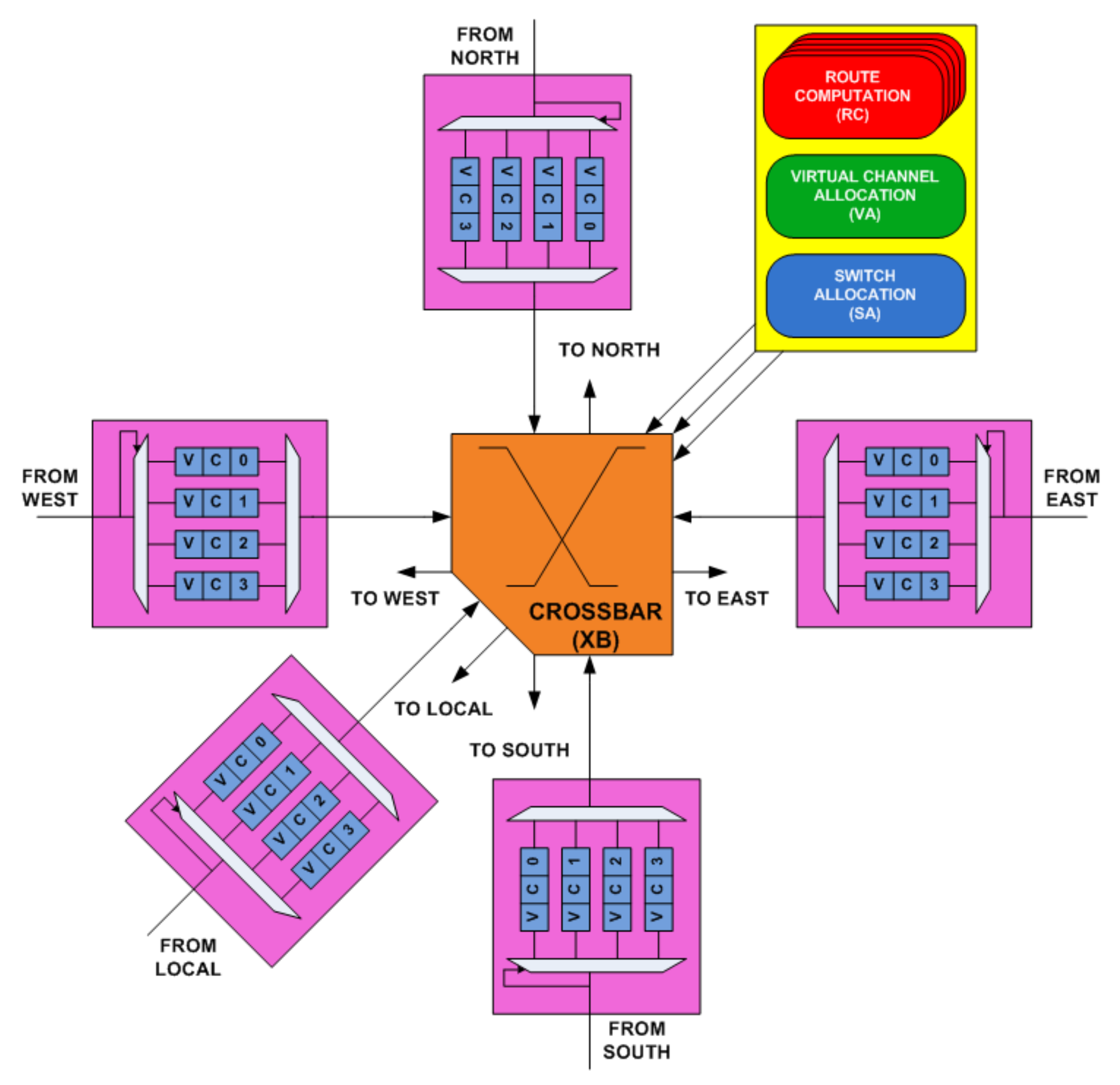
3. Generic NoC Router Architecture
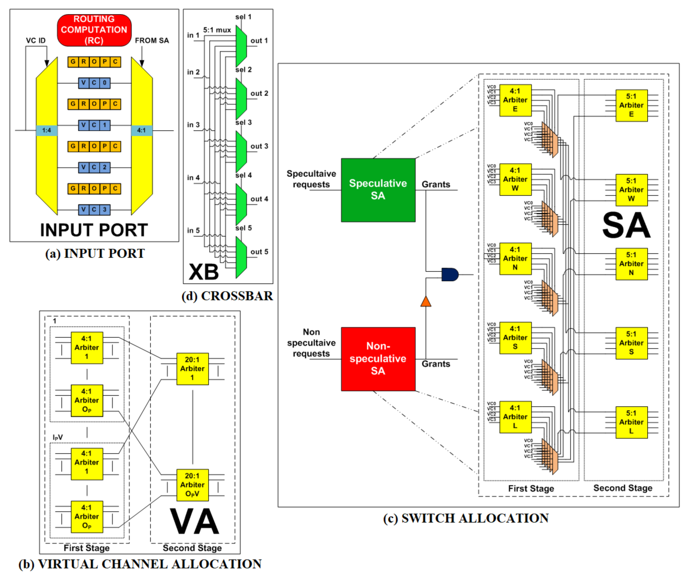
3.1. Overview of Router Input Port
3.2. Overview of Pipeline Stages
3.2.1. RC Stage
3.2.2. VA Stage
3.2.3. SA Stage
3.2.4. XB Stage
4. Effects of Fault on Router Pipeline
4.1. RC Stage Fault Scenario
4.2. VA Stage Fault Scenario
4.3. SA Stage Fault Scenario
4.4. XB Stage Fault Scenario
5. NoCGuard Router Micro-Architecture
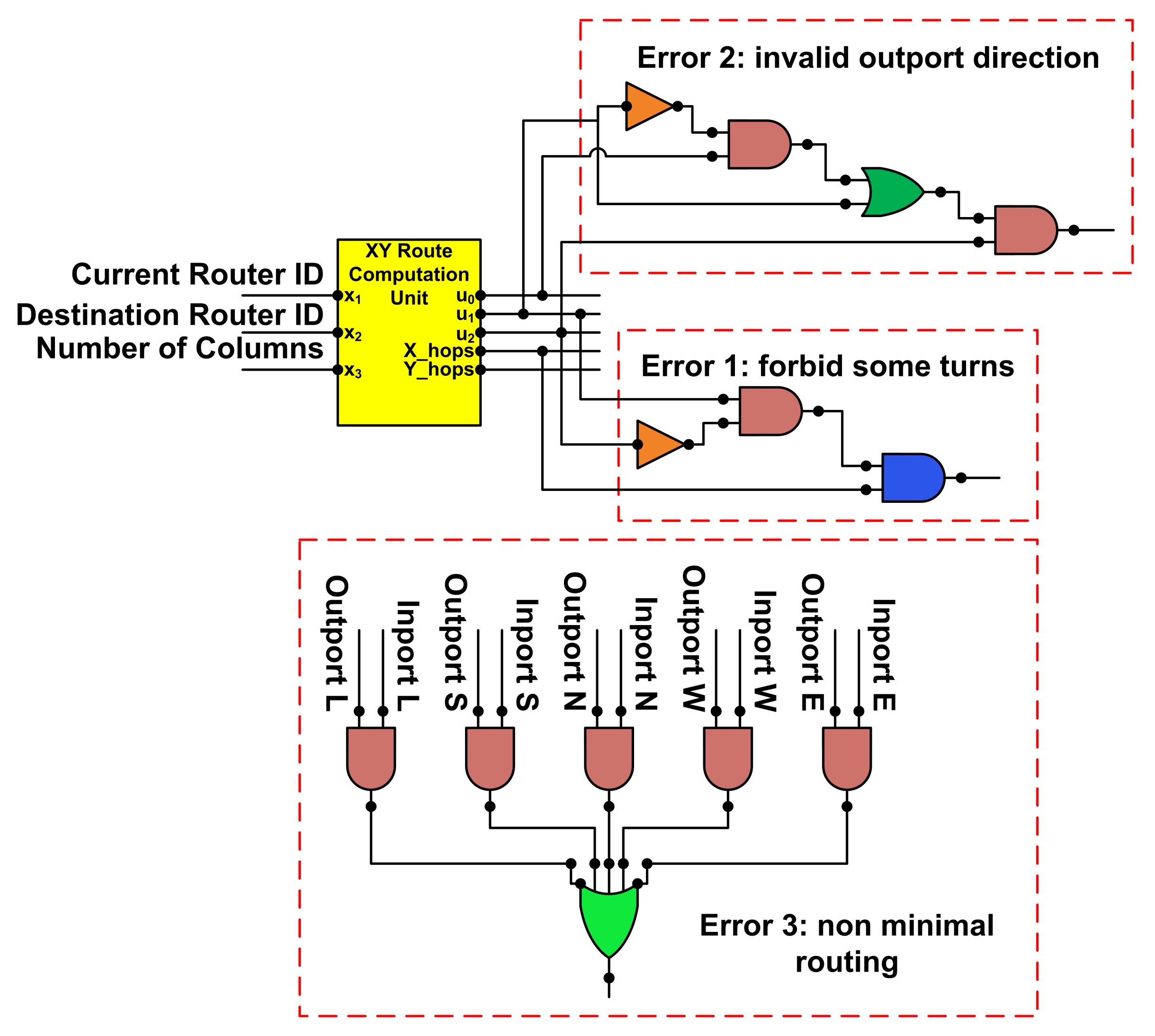
5.1. RC Stage Fault-Tolerant Design
5.2. VA Stage Fault-Tolerant Design
5.3. SA Stage Fault-Tolerant Design
5.4. XB Stage Fault-Tolerant Design
6. Performance Analysis
Hardware Overhead Analysis
7. Reliability Analysis
7.1. Mean Time to Failure (MTTF) Analysis
7.1.1. Failures in Time (FIT) Estimation Model
7.1.2. FIT Rate of Generic 2-Stage NoC Router
7.1.3. FIT Rate of Correction Circuitry
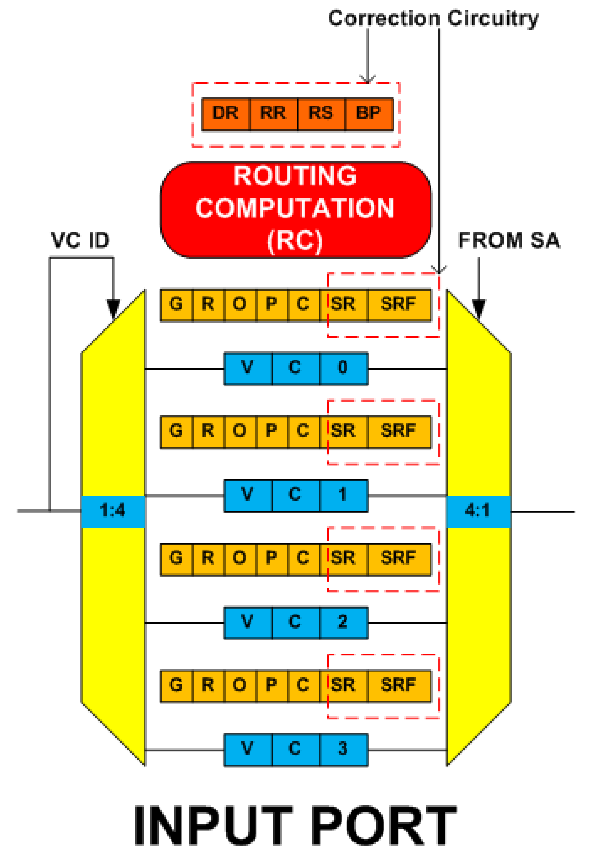
- RC Pipeline StageThis stage uses the resource borrowing and the double routing strategy for fault tolerance. Correction circuitry consists of four new state fields namely ‘DR’, ‘RR’, ‘RS, and ‘BP’. Implementation requires 6-bit D flip-flop (DFF) for ‘DR’, 3-bit DFF for ‘RR’, 2-bit DFF for ‘RS’ and 3-bit DFF for the ‘BP’ field. The double routing strategy does not incur any correction circuitry.
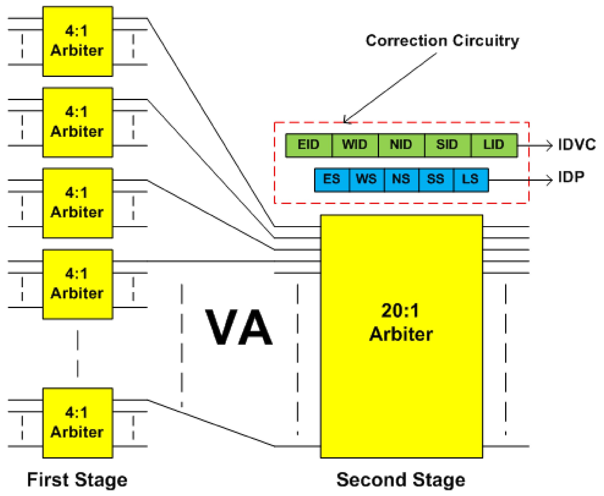
- VA Pipeline StageThis stage uses the default winner strategy for fault tolerance. Correction circuitry consists of two new state fields namely ‘IDP’ and ‘IDVC’. Implementation requires 5-bit DFF for the ‘IDP’ and 10-bit DFF for the ‘IDVC’ field.
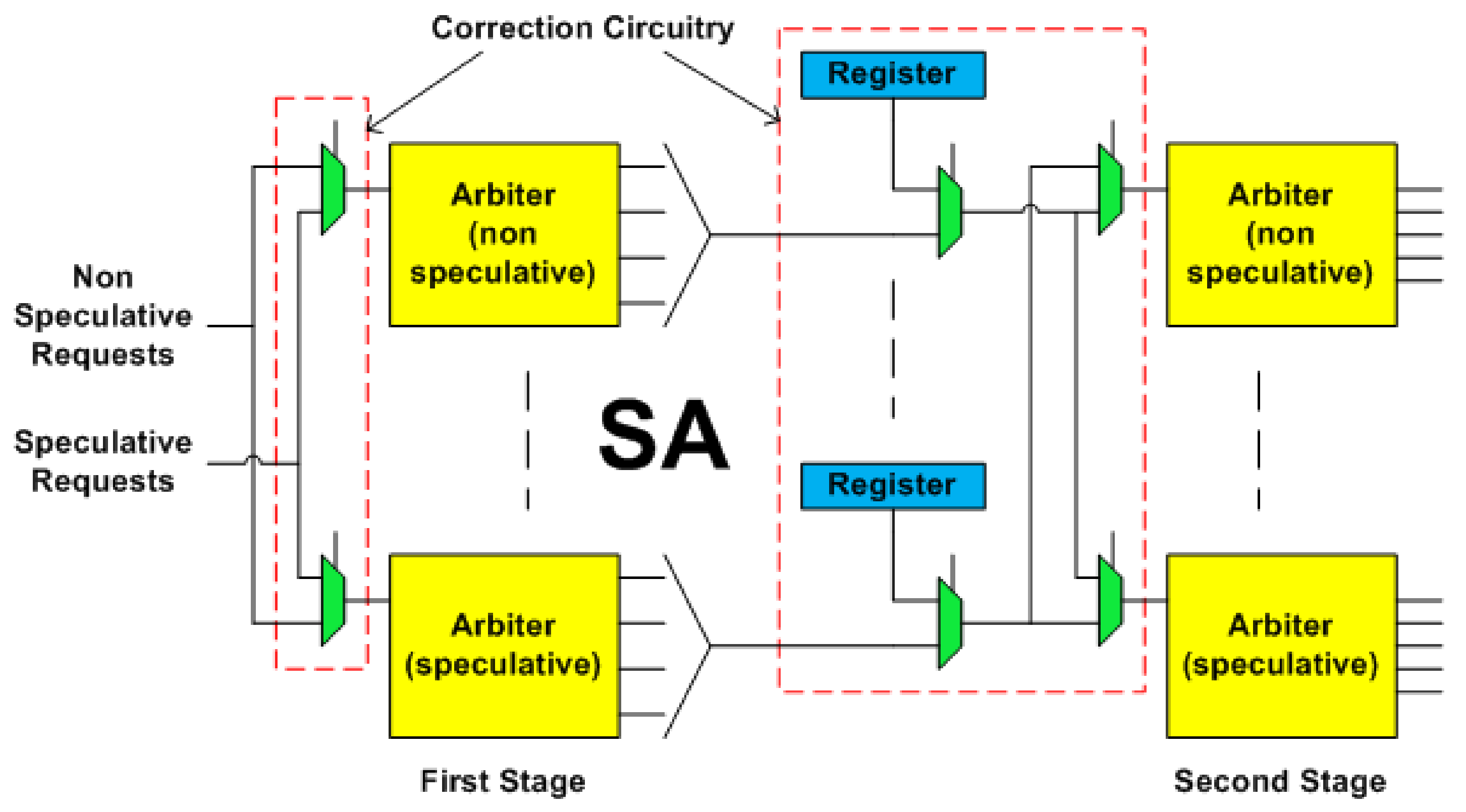
- SA Pipeline StageThis stage uses the runtime arbiter selection and the default winner strategy for fault tolerance. Correction circuity for the runtime arbiter selection strategy consists of 2:1 multiplexers. Correction circuity for the default winner strategy consists of 2:1 multiplexers and 2-bit DFF registers (reg). SA stage also facilitates the fault tolerance in the XB stage. For that, it adds two new state fields, namely ‘SR’ and ‘SRF’ to each input VC. Implementation requires 3-bit DFF for the ‘SR’ and 1-bit DFF for the ‘SRF’ field.
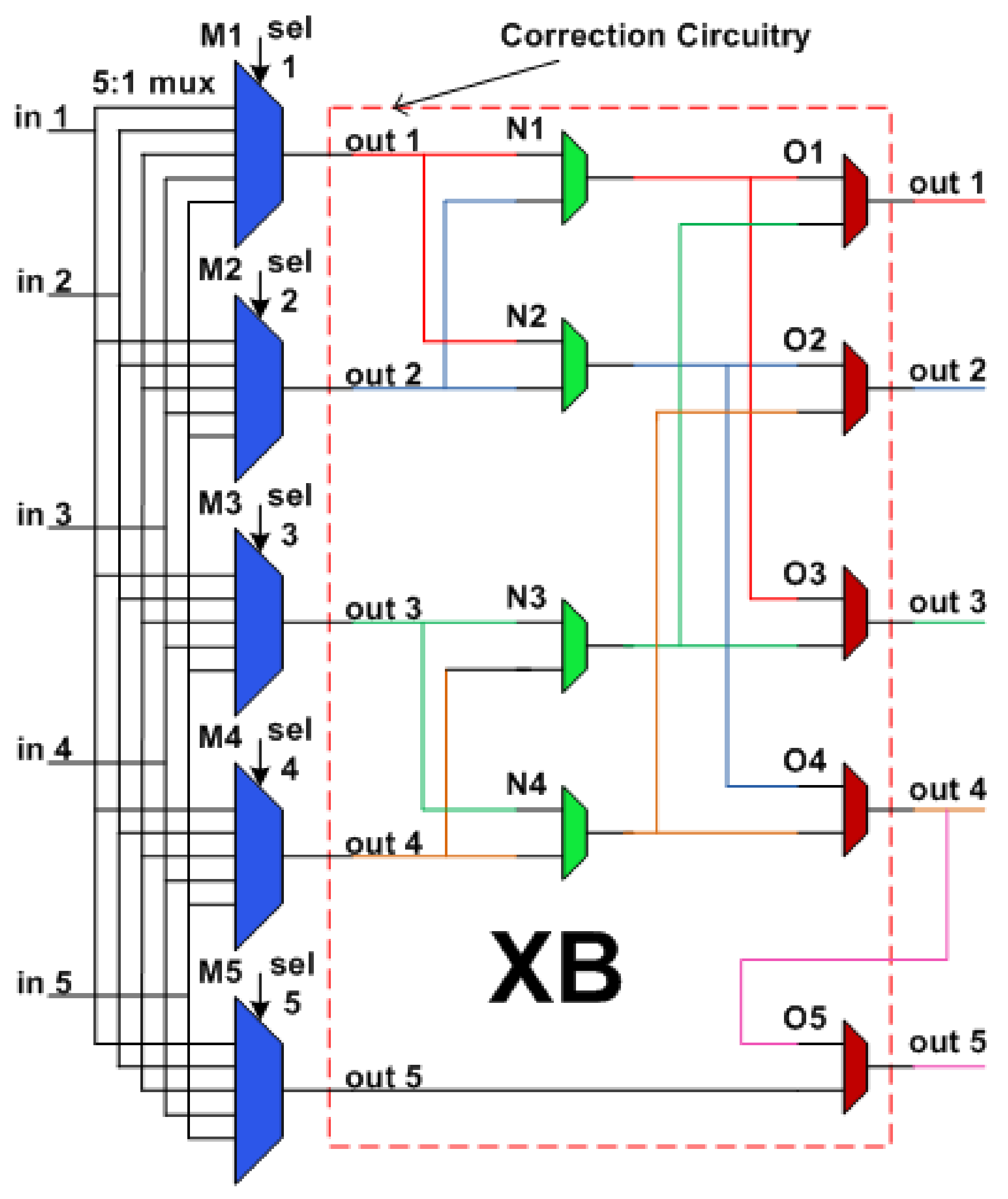
- XB Pipeline StageThis stage uses the multiple secondary bypass paths strategy for fault tolerance. Correction circuitry consists of 32-bit 2:1 multiplexers.
7.1.4. MTTF Estimation of NoCGuard Router
7.2. Mean Defects to Failure (MDTF) Analysis
7.2.1. Fault Estimation of Pipeline Stages
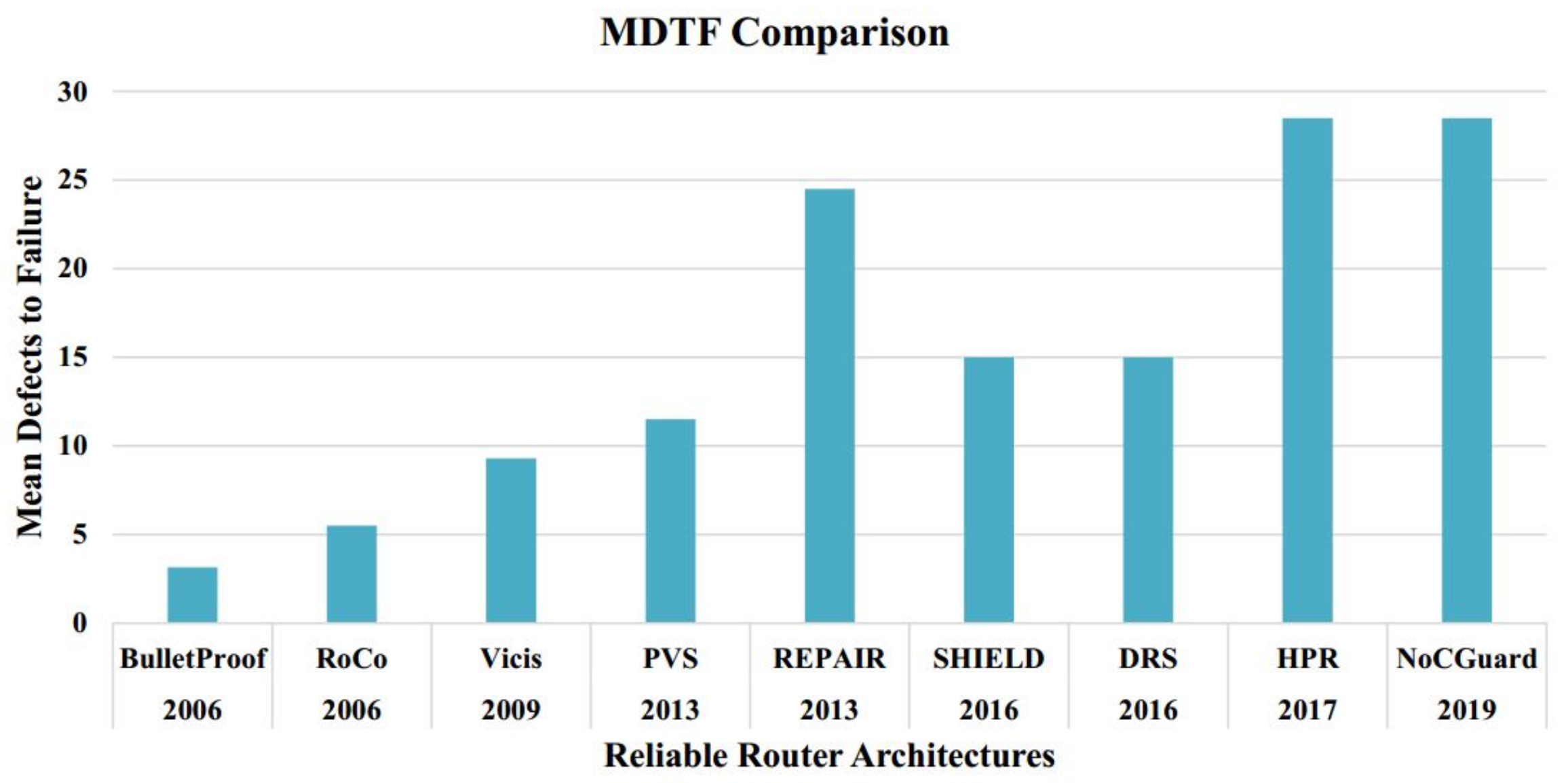
- RC Pipeline StageThis stage uses the resource borrowing and the double routing strategy for fault tolerance. If all five RC units of a current router and four RC units of adjacent router become faulty, the router still works due to borrowing and double routing strategy. Therefore, the router tolerates a maximum of 9 faults. On the other hand, if all five RC units of the adjacent router become faulty then it does not compute current as well as lookahead route. Therefore, a minimum of 5 faults causes RC failure.
- VA Pipeline StageThis stage uses the default winner strategy for fault tolerance. It tolerates faults in the arbiters of the first stage by providing their default winner at the second stage of the VA. If all twenty-first stage arbiters at an input port become faulty, then VA proceeds by using their default winner at corresponding twenty-second stage arbiters. Therefore, the router can tolerate the maximum 20 faults. There are four VCs per port. For every output port VC, there is one arbiter in the second stage of the VA. If all four arbiters associated with an output port become faulty, the output port becomes inaccessible. Therefore, a minimum of 4 faults causes VA failure.
- SA Pipeline StageThis stage uses the runtime arbiter selection and the default winner strategy for fault tolerance. If all ten arbiters of the non-speculative set and ten arbiters of the speculative set become faulty, then SA proceeds using the default winner strategy. Thus, the router tolerates a maximum of 20 faults. If for an input port, a speculative and a non-speculative arbiter, along with their default winner registers become faulty, SA fails. Therefore, a minimum of 4 faults causes SA failure.
- XB Pipeline StageThis stage uses the multiple bypass paths strategy for fault tolerance. A fault in the primary multiplexer associated with an output port makes it unreachable. We provide three secondary bypass paths to access an output port. For local output port, four secondary paths are present, and its primary multiplexer does not take part in making secondary paths for any other output port. Hence, it is not considered in this calculation. Therefore, the router tolerates a maximum 3 faults. If all four primary multiplexers become faulty, output ports become unreachable. Therefore, a minimum of 4 faults causes XB failure.
7.2.2. MDTF Estimation of NoCGuard Router
7.3. SPF Analysis
8. Latency Analysis
9. Conclusions
Author Contributions
Acknowledgments
Conflicts of Interest
References
- ITRS. International Technology Roadmap for Semiconductors; Technical Report; ITRS: Hong Kong, China, 2011. [Google Scholar]
- Borkar, S. Thousand Core Chips: A Technology Perspective. In Proceedings of the 44th Annual Design Automation Conference, San Diego, CA, USA, 4 June 2007; pp. 746–749. [Google Scholar] [CrossRef]
- Dally, W.J.; Towles, B. Route packets, not wires: On-chip interconnection networks. In Proceedings of the 38th Design Automation Conference (IEEE Cat. No.01CH37232), Las Vegas, NV, USA, 23 May 2001; pp. 684–689. [Google Scholar] [CrossRef]
- Benini, L.; De Micheli, G. Networks on chips: A new SoC paradigm. Computer 2002, 35, 70–78. [Google Scholar] [CrossRef]
- Salminen, E.; Kulmala, A.; Hamalainen, T.D. On network-on-chip comparison. In Proceedings of the 10th Euromicro Conference on Digital System Design Architectures, Methods and Tools (DSD 2007), Lubeck, Germany, 31 August 2007; pp. 503–510. [Google Scholar] [CrossRef]
- Borkar, S. Design challenges of technology scaling. IEEE Micro 1999, 19, 23–29. [Google Scholar] [CrossRef]
- Borkar, S. Designing reliable systems from unreliable components: The challenges of transistor variability and degradation. IEEE Micro 2005, 25, 10–16. [Google Scholar] [CrossRef]
- Radetzki, M.; Feng, C.; Zhao, X.; Jantsch, A. Methods for Fault Tolerance in Networks-on-chip. ACM Comput. Surv. 2013, 46, 1–38. [Google Scholar] [CrossRef]
- Oussalah, S.; Nebel, F. On the oxide thickness dependence of the time-dependent-dielectric-breakdown. In Proceedings of the 1999 IEEE Hong Kong Electron Devices Meeting (Cat. No.99TH8458), Hong Kong, China, 26 June 1999; pp. 42–45. [Google Scholar] [CrossRef]
- Barsky, R.; Wagner, I.A. Electromigration-dependent parametric yield estimation. In Proceedings of the 2004 11th IEEE International Conference on Electronics, Circuits and Systems, Tel Aviv, Israel, 13 December 2004; pp. 121–124. [Google Scholar] [CrossRef]
- Mahapatra, S.; Bharath Kumar, P.; Dalei, T.R.; Sana, D.; Alam, M.A. Mechanism of negative bias temperature instability in CMOS devices: Degradation, recovery and impact of nitrogen. IEDM Technical Digest. IEEE Int. Electron Devices Meet. 2004, 2004, 105–108. [Google Scholar] [CrossRef]
- Groeseneken, G.V. Hot carrier degradation and ESD in submicrometer CMOS technologies: How do they interact? IEEE Trans. Device Mater. Reliab. 2001, 1, 23–32. [Google Scholar] [CrossRef]
- JEDEC. Failure Mechanisms and Models for Semiconductor Devices; Technical Report; JEDEC: Arlington, VA, USA, 2009. [Google Scholar]
- Kuhn, K.J. Reducing Variation in Advanced Logic Technologies: Approaches to Process and Design for Manufacturability of Nanoscale CMOS. In Proceedings of the 2007 IEEE International Electron Devices Meeting, Washington, DC, USA, 10 December 2007; pp. 471–474. [Google Scholar] [CrossRef]
- May, T.C.; Woods, M.H. Alpha-particle-induced soft errors in dynamic memories. IEEE Trans. Electron Devices 1979, 26, 2–9. [Google Scholar] [CrossRef]
- Sai-Halasz, G.A.; Wordeman, M.R.; Dennard, R.H. Alpha-Particle-Induced Soft Error Rate in VLSI Circuits. IEEE J. Solid-State Circuits 1982, 17, 355–361. [Google Scholar] [CrossRef]
- Ziegler, J.F. Terrestrial cosmic ray intensities. IBM J. Res. Dev. 1998, 42, 117–140. [Google Scholar] [CrossRef]
- Werner, S.; Navaridas, J.; Luján, M. A Survey on Design Approaches to Circumvent Permanent Faults in Networks-on-Chip. ACM Comput. Surv. 2016, 48, 1–36. [Google Scholar] [CrossRef]
- Ibrahim, M.; Baloch, N.K.; Anjum, S.; Zikria, Y.B.; Kim, S.W. An Energy Efficient and Low Overhead Fault Mitigation Technique for Internet of Thing Edge Devices Reliable On-Chip Communication. Software: Practice and Experience. Available online: https://onlinelibrary.wiley.com/doi/pdf/10.1002/spe.2796 (accessed on 16 February 2020).
- Feng, C.; Lu, Z.; Jantsch, A.; Zhang, M.; Xing, Z. Addressing Transient and Permanent Faults in NoC With Efficient Fault-Tolerant Deflection Router. IEEE Trans. Very Large Scale Integr. Syst. 2013, 21, 1053–1066. [Google Scholar] [CrossRef]
- Ebrahimi, M.; Wang, J.; Huang, L.; Daneshtalab, M.; Jantsch, A. Rescuing healthy cores against disabled routers. In Proceedings of the 2014 IEEE International Symposium on Defect and Fault Tolerance in VLSI and Nanotechnology Systems (DFT), Amsterdam, The Netherlands, 1 October 2014; pp. 98–103. [Google Scholar] [CrossRef]
- Constantinides, K.; Plaza, S.; Blome, J.; Zhang, B.; Bertacco, V.; Mahlke, S.; Austin, T.; Orshansky, M. BulletProof: A defect-tolerant CMP switch architecture. In Proceedings of the Twelfth International Symposium on High-Performance Computer Architecture, Austin, TX, USA, 11 February 2006; pp. 5–16. [Google Scholar] [CrossRef]
- Das, C.R.; Yousif, M.S.; Narayanan, V.; Dongkook, P.; Nicopoulos, C.; Jongman, K.; Das, C.R.; Yousif, M.S.; Narayanan, V.; Dongkook, P.; et al. A Gracefully Degrading and Energy-Efficient Modular Router Architecture for On-Chip Networks. In Proceedings of the 33rd International Symposium on Computer Architecture (ISCA’06), Boston, MA, USA, 17 June 2006; pp. 4–15. [Google Scholar] [CrossRef]
- Fick, D.; DeOrio, A.; Jin, H.; Bertacco, V.; Blaauw, D.; Sylvester, D. Vicis: A reliable network for unreliable silicon. In Proceedings of the 2009 46th ACM/IEEE Design Automation Conference, San Francisco, CA, USA, 26 July 2009; pp. 812–817. [Google Scholar] [CrossRef]
- Xie, L.; Mei, K.; Li, Y. REPAIR: A Reliable Partial-Redundancy-Based Router in NoC. In Proceedings of the 2013 IEEE Eighth International Conference on Networking, Architecture and Storage, Xian, Shaanxi, China, 17 July 2013; pp. 173–177. [Google Scholar] [CrossRef]
- Latif, K.; Rahmani, A.M.; Nigussie, E.; Seceleanu, T.; Radetzki, M.; Tenhunen, H. Partial Virtual Channel Sharing: A Generic Methodology to Enhance Resource Management and Fault Tolerance in Networks-on-Chip. J. Electron. Test. 2013, 29, 431–452. [Google Scholar] [CrossRef]
- Valinataj, M.; Shahiri, M. A low-cost, fault-tolerant and high-performance router architecture for on-chip networks. Microprocess. Microsyst. 2016, 45, 151–163. [Google Scholar] [CrossRef]
- Poluri, P.; Louri, A. Shield: A Reliable Network-on-Chip Router Architecture for Chip Multiprocessors. IEEE Trans. Parallel Distrib. Syst. 2016, 27, 3058–3070. [Google Scholar] [CrossRef]
- Wang, L.; Ma, S.; Li, C.; Chen, W.; Wang, Z. A high performance reliable NoC router. Integration 2017, 58, 583–592. [Google Scholar] [CrossRef]
- Mohammed, H.J.; Flayyih, W.N.; Rokhani, F.Z. Tolerating Permanent Faults in the Input Port of the Network on Chip Router. J. Low Power Electron. Appl. 2019, 9. [Google Scholar] [CrossRef]
- Putkaradze, T.; Azad, S.P.; Niazmand, B.; Raik, J.; Jervan, G. Fault-resilient NoC router with transparent resource allocation. In Proceedings of the 2017 12th International Symposium on Reconfigurable Communication-centric Systems-on-Chip (ReCoSoC), Madrid, Spain, 31 March 2017; pp. 1–8. [Google Scholar] [CrossRef]
- Li, C.; Yang, M.; Ampadu, P. An Energy-Efficient NoC Router with Adaptive Fault-Tolerance Using Channel Slicing and On-Demand TMR. IEEE Trans. Emerg. Top. Comput. 2018, 6, 538–550. [Google Scholar] [CrossRef]
- Wang, J.; Ebrahimi, M.; Huang, L.; Xie, X.; Li, Q.; Li, G.; Jantsch, A. Efficient Design-for-Test Approach for Networks-on-Chip. IEEE Trans. Comput. 2019, 68, 198–213. [Google Scholar] [CrossRef]
- Prodromou, A.; Panteli, A.; Nicopoulos, C.; Sazeides, Y. NoCAlert: An On-Line and Real-Time Fault Detection Mechanism for Network-on-Chip Architectures. In Proceedings of the 2012 45th Annual IEEE/ACM International Symposium on Microarchitecture, Vancouver, BC, Canada, 1 December 2012; pp. 60–71. [Google Scholar] [CrossRef]
- Dally, W.; Towles, B. Principles and Practices of Interconnection Networks; Morgan Kaufmann Publishers Inc.: San Francisco, CA, USA, 2003. [Google Scholar]
- Peh, L.; Dally, W.J. A delay model and speculative architecture for pipelined routers. In Proceedings of the HPCA Seventh International Symposium on High-Performance Computer Architecture, Monterrey, Nuevo Leon, Mexico, 19 January 2001; pp. 255–266. [Google Scholar] [CrossRef]
- Martins, M.; Matos, J.M.; Ribas, R.P.; Reis, A.; Schlinker, G.; Rech, L.; Michelsen, J. Open Cell Library in 15 nm FreePDK Technology. In Proceedings of the 2015 Symposium on International Symposium on Physical Design, Monterey, CA, USA, 29 March 2015; pp. 171–178. [Google Scholar] [CrossRef]
- Gaver, D.P. Time to Failure and Availability of Paralleled Systems with Repair. IEEE Trans. Reliab. 1963, R-12, 30–38. [Google Scholar] [CrossRef]
- Shin, J.; Zyuban, V.; Hu, Z.; Rivers, J.A.; Bose, P. A Framework for Architecture-Level Lifetime Reliability Modeling. In Proceedings of the 37th Annual IEEE/IFIP International Conference on Dependable Systems and Networks (DSN’07), Edinburgh, UK, 25 June 2007; pp. 534–543. [Google Scholar] [CrossRef]
- Wu, E.Y.; Nowak, E.J.; Vayshenker, A.; Lai, W.L.; Harmon, D.L. CMOS scaling beyond the 100-nm node with silicon-dioxide-based gate dielectrics. IBM J. Res. Dev. 2002, 46, 287–298. [Google Scholar] [CrossRef]
- Srinivasan, J.; Adve, S.V.; Bose, P.; Rivers, J.A. The case for lifetime reliability-aware microprocessors. In Proceedings of the 31st Annual International Symposium on Computer Architecture, Munchen, Germany, 23 June 2004; pp. 276–287. [Google Scholar] [CrossRef]
- Kouvatsos, D.D. Probability Statistics with Reliability, Queueing and Computer Science Applications-K. S. Trivedi. IEEE Trans. Educ. 1985, 28, 116. [Google Scholar] [CrossRef]
- Binkert, N.; Beckmann, B.; Black, G.; Reinhardt, S.K.; Saidi, A.; Basu, A.; Hestness, J.; Hower, D.R.; Krishna, T.; Sardashti, S.; et al. The Gem5 Simulator. SIGARCH Comput. Archit. News 2011, 39, 1–7. [Google Scholar] [CrossRef]
- Agarwal, N.; Krishna, T.; Peh, L.; Jha, N.K. GARNET: A detailed on-chip network model inside a full-system simulator. In Proceedings of the 2009 IEEE International Symposium on Performance Analysis of Systems and Software, Boston, MA, USA, 26 April 2009; pp. 33–42. [Google Scholar] [CrossRef]
- Bienia, C.; Kumar, S.; Singh, J.P.; Li, K. The PARSEC benchmark suite: Characterization and architectural implications. In Proceedings of the 2008 International Conference on Parallel Architectures and Compilation Techniques (PACT), Toronto, ON, Canada, 4 October 2008; pp. 72–81. [Google Scholar]
- Woo, S.C.; Ohara, M.; Torrie, E.; Singh, J.P.; Gupta, A. The SPLASH-2 programs: Characterization and methodological considerations. In Proceedings of the 22nd Annual International Symposium on Computer Architecture, Santa Margherita Ligure, Italy, 22 June 1995; pp. 24–36. [Google Scholar] [CrossRef]


| Pipeline Stages | Component | No of Components | ||
|---|---|---|---|---|
| RC | 6-bit comparator | 11.7 | 10 | 117 |
| VA | 20:1 arbiter | 36.7 | 20 | 1474 |
| 4:1 arbiter | 7.4 | 100 | ||
| SA | 5:1 arbiter | 9.3 | 10 | 215 |
| 4:1 arbiter | 7.4 | 10 | ||
| 4:1 multiplexer | 4.8 | 10 | ||
| XB | 32-bit 2:1 multiplexer | 204.8 | 5 | 1024 |
| Pipeline Stages | Component | No of Components | ||
|---|---|---|---|---|
| RC | 6-bit DFF (DR) | 3 | 5 | 35 |
| 3-bit DFF (RR) | 1.5 | 5 | ||
| 2-bit DFF (RS) | 1 | 5 | ||
| 3-bit DFF (BP) | 1.5 | 5 | ||
| VA | 5-bit DFF (IDP) | 2.5 | 20 | 150 |
| 10-bit DFF (IDVC) | 5 | 20 | ||
| SA | 2:1 multiplexer | 1.6 | 30 | 98 |
| 3-bit DFF (Reg) | 1 | 10 | ||
| 2-bit DFF (SR) | 1.5 | 20 | ||
| 3-bit DFF (SRF) | 0.5 | 20 | ||
| XB | 32-bit 5:1 multiplexer | 52.3 | 9 | 470.7 |
| Router Architecture | Area Overhead | Mean No of Faults | SPF |
|---|---|---|---|
| BulletProof | 52% | 3.15 | 2.07 |
| VICIS | 42% | 9.3 | 6.55 |
| REPAIR | 50% | 24.5 | 16.34 |
| SHIELD | 34% | 15 | 11.19 |
| HPR | 30% | 28.5 | 21.92 |
| NoCGuard | 28% | 28.5 | 22.26 |
© 2020 by the authors. Licensee MDPI, Basel, Switzerland. This article is an open access article distributed under the terms and conditions of the Creative Commons Attribution (CC BY) license (http://creativecommons.org/licenses/by/4.0/).
Share and Cite
Shafique, M.A.; Baloch, N.K.; Baig, M.I.; Hussain, F.; Zikria, Y.B.; Kim, S.W. NoCGuard: A Reliable Network-on-Chip Router Architecture. Electronics 2020, 9, 342. https://doi.org/10.3390/electronics9020342
Shafique MA, Baloch NK, Baig MI, Hussain F, Zikria YB, Kim SW. NoCGuard: A Reliable Network-on-Chip Router Architecture. Electronics. 2020; 9(2):342. https://doi.org/10.3390/electronics9020342
Chicago/Turabian StyleShafique, Muhammad Akmal, Naveed Khan Baloch, Muhammad Iram Baig, Fawad Hussain, Yousaf Bin Zikria, and Sung Won Kim. 2020. "NoCGuard: A Reliable Network-on-Chip Router Architecture" Electronics 9, no. 2: 342. https://doi.org/10.3390/electronics9020342
APA StyleShafique, M. A., Baloch, N. K., Baig, M. I., Hussain, F., Zikria, Y. B., & Kim, S. W. (2020). NoCGuard: A Reliable Network-on-Chip Router Architecture. Electronics, 9(2), 342. https://doi.org/10.3390/electronics9020342


