Review

Reconfigurable Antennas: Switching Techniques—A Survey

by
Naser Ojaroudi Parchin
1,*,
Haleh Jahanbakhsh Basherlou
2,
Yasir I. A. Al-Yasir
1,
Ahmed M. Abdulkhaleq
1,3 and
Raed A. Abd-Alhameed
1
1
Faculty of Engineering and Informatics, University of Bradford, Bradford BD7 1DP, UK
2
Bradford College, University of Bradford, West Yorkshire, Bradford BD7 1AY, UK
3
SARAS Technology Limited, Leeds LS12 4NQ, UK
*
Author to whom correspondence should be addressed.
Electronics 2020, 9(2), 336; https://doi.org/10.3390/electronics9020336
Submission received: 31 December 2019 / Revised: 28 January 2020 / Accepted: 6 February 2020 / Published: 15 February 2020
(This article belongs to the Section Microwave and Wireless Communications)

Abstract

:
Due to the fast development of wireless communication technology, reconfigurable antennas with multimode and cognitive radio operation in modern wireless applications with a high-data rate have drawn very close attention from researchers. Reconfigurable antennas can provide various functions in operating frequency, beam pattern, polarization, etc. The dynamic tuning can be achieved by manipulating a certain switching mechanism through controlling electronic, mechanical, physical or optical switches. Among them, electronic switches are the most popular in constituting reconfigurable antennas due to their efficiency, reliability and ease of integrating with microwave circuitry. In this paper, we review different implementation techniques for reconfigurable antennas. Different types of effective implementation techniques have been investigated to be used in various wireless communication systems such as satellite, multiple-input multiple-output (MIMO), mobile terminals and cognitive radio communications. Characteristics and fundamental properties of the reconfigurable antennas are investigated.

1. Introduction

Rapid growth in the area of modern wireless communication systems has led to demand for multi-mode reconfigurable antennas to be used in various wireless services [1,2]. Reconfigurability of an antenna refers to the capacity to adjust a radiator’s characteristics in terms of resonant frequency, radiation pattern or polarization [3,4,5]. A frequency reconfigurable antenna is arguably the most practical option for switching its operation to the desired frequency, instead of utilizing a number of antennas operating in different frequencies for signal transmission or reception [6,7,8]. In addition to improved performance, multi-frequency operation in a single antenna reduces space and cost. Pattern reconfigurable antennas are attractive in applications such as surveillance and tracking because they produce more than one radiation pattern with different directivity at the same operating frequency [9,10]. In addition, manipulation of patterns is useful in avoiding noise sources, mitigating electronic jamming, improving security and increasing energy efficiency. The polarization reconfigurable antennas can switch the polarization characteristics of the radiators between various linear polarizations, right-hand circular polarization (RHCP), left-hand circular polarization (LHCP) and any number of elliptical polarizations [11,12,13].
Due to these attractive features, reconfigurable antennas have received considerable attention, and a number of works have been demonstrated in past years [14,15]. Furthermore, several review and survey papers have been published recently [16,17]. However, these reviews have only focused on electrical reconfiguration with active elements such as positive–intrinsic–negative (PIN) diodes. In [18], various kinds of reconfigurable antennas including radiation pattern reconfigurable antenna, polarization reconfigurable antenna and a combination of radiation and frequency reconfigurable antenna are discussed. In addition, more details of different types of reconfigurable antennas are described in [19]. Unlike the reported reviews, we investigate here different types of effective implementation techniques including not only electronic switching but also other possible switching techniques of reconfigurable antennas. In order to demonstrate the reconfigurable antennas, various effective implementation techniques have been proposed to be used in different wireless systems such as satellite, multiple-input multiple-output (MIMO) and cognitive ratio communications, which are classified as below:
  • Electrical reconfiguration;
  • Optical reconfiguration;
  • Physical reconfiguration;
  • Reconfigurable antennas with smart materials.
The most common technique is electrical reconfiguration, which uses active elements such as positive–intrinsic–negative (PIN) diodes, varactors and radiofrequency micro-electromechanical system (RFMEMS) switches [20,21,22,23]. Compared to RFMEMS switches, PIN diodes have acceptable performance and a low price. Another technique is called optical reconfiguration, which relies on photoconductive switching elements [24,25]. The antenna reconfigurable characteristic can also be implemented by altering the structure of the antenna—this is called the mechanical reconfiguration method [26,27]. Apart from the mentioned techniques, the antenna can be also reconfigured using smart materials in the antenna configuration [28]. In this section, we investigate different types of reconfigurable antenna implementation techniques by providing some detailed examples.

2. Electrical Reconfiguration
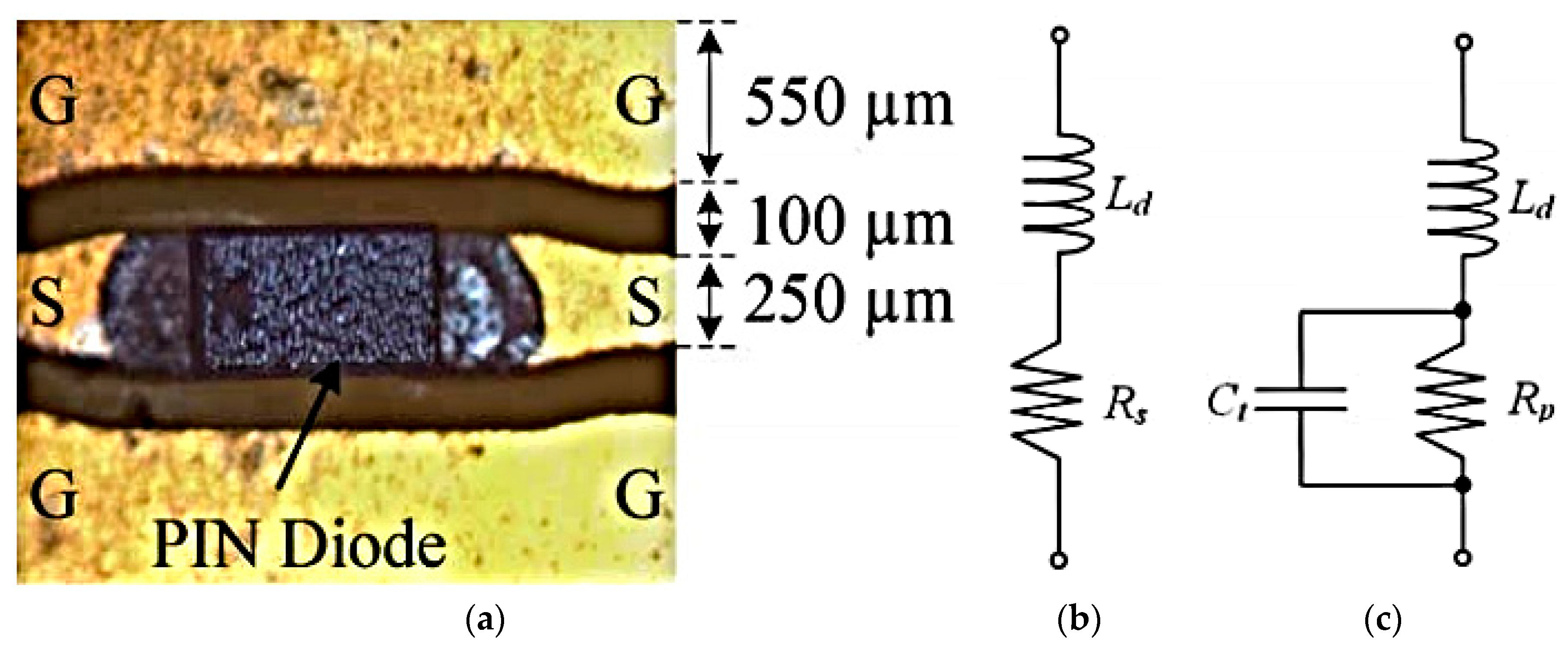
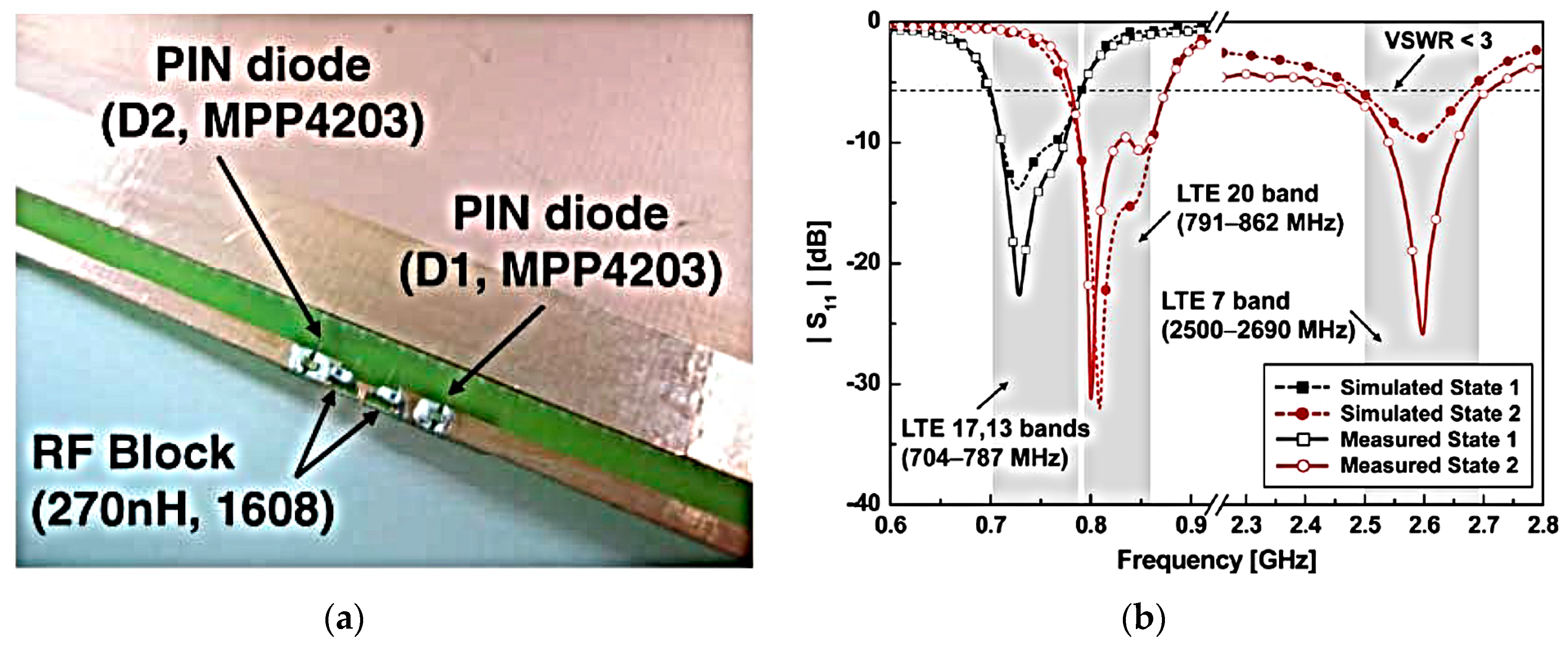
In this type of reconfiguration method, the antenna characteristics are changed using electronic switching components such as PIN diodes, varactors or MEMS. Using these switches, the antenna structure can be reconfigured, which causes the redistribution of the surface current and alters the antenna’s fundamental characteristics in terms of frequency, radiation pattern and polarization. The implementation of such a reconfigurable antenna with switching elements is easy and has received lots of attention in research [29,30,31,32]. Next, different methods along with some examples of electrically reconfigurable antennas to obtain the corresponding reconfigurability function with their own advantages and disadvantages using PIN diodes, varactors or MEMS switches are described.

2.1. PIN Diodes

The electrical parameters of the diode equivalent model with forward and reverse biases in the ON and OFF states are illustrated in Figure 1. PIN diodes are widely used as the switching components in different wireless systems. For reconfigurable antennas, an additional dimension for the RF and the direct current (DC) blocks is required and should be considered in the design of the antenna [33]. In Reference [34], a frequency reconfigurable MIMO antenna is presented for laptop applications. The schematic and the performance of the antenna are represented in Figure 2. As can be observed, its configuration contains a pair of planar inverted-F antenna (PIFA) elements and a T-shaped DC line feed structure. Two PIN diodes are embedded in conjunction with the proximity-coupled feeding. For different states of the employed diodes, the operation frequency of the antenna can be tuned to cover LTE 17/13 and LTE 20/7 bands including 704–787, 791–862 and 2500–2690 MHz.
The PIN diode needs a high tuning speed, a high direct current (DC) bias current in the ON-state and a high power-handling capacity. However, it is very reliable and extremely low-cost which makes it a good choice for the reconfiguration technique.

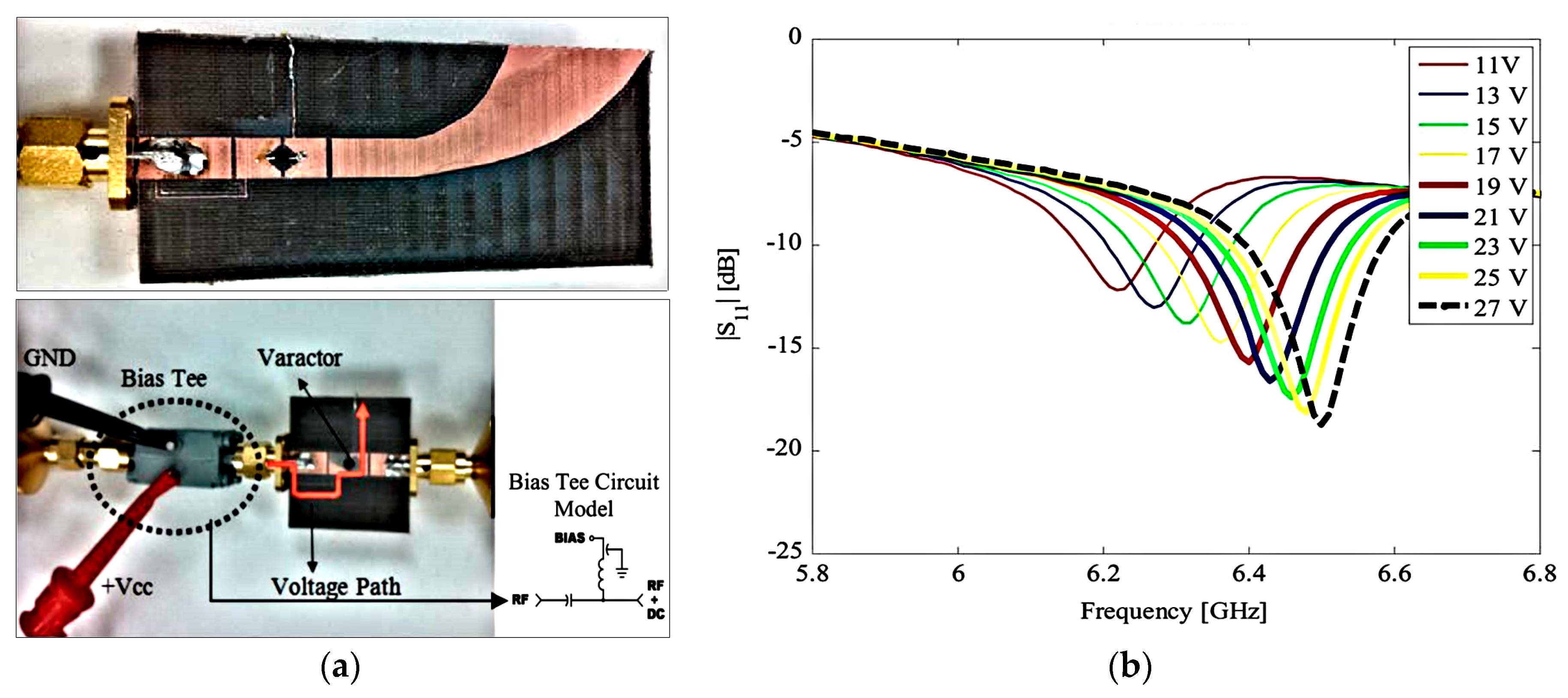
2.2. Tunable Varactors
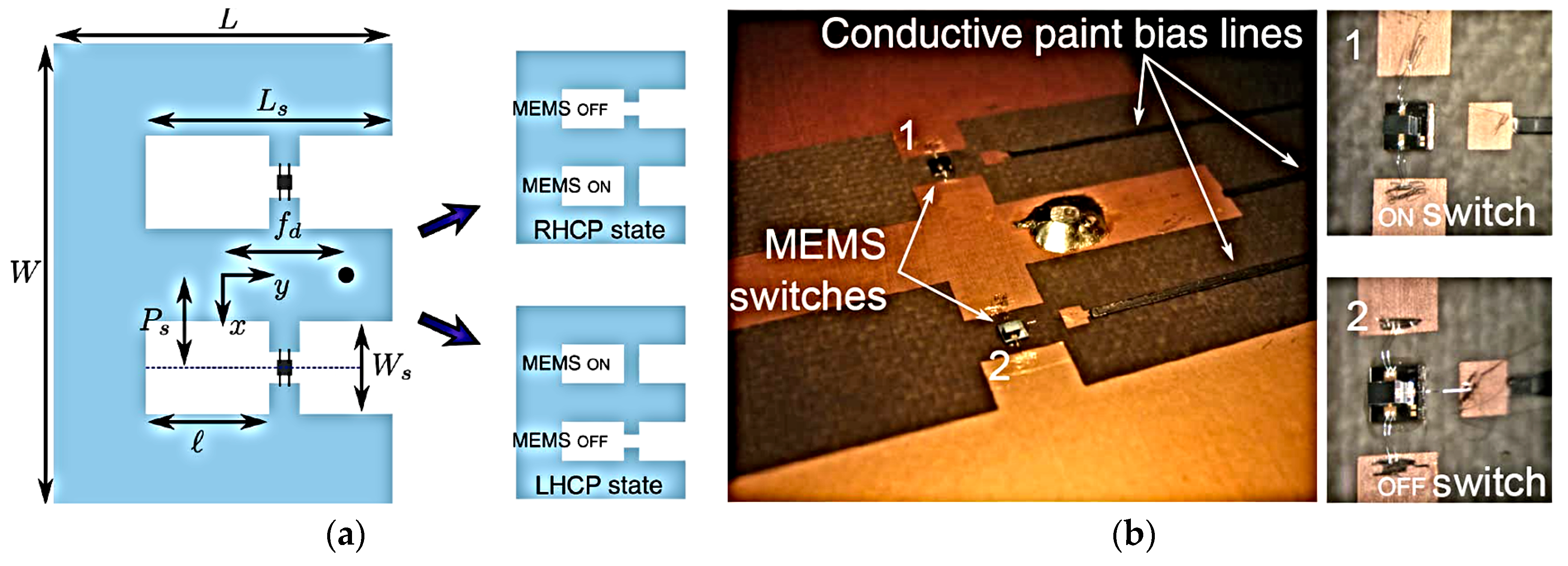
Varactors can also be embedded into the reconfigurable antenna, either on its radiating patch or the feeding line. It requires a direct DC-voltage source. By changing the voltage levels of the varactor, its capacitance changes, which leads to tune the antenna performance. Integrating varactors in reconfigurable designs is a common way to achieve the frequency tuning function. A varactor-loaded reconfigurable filtenna is introduced in [35]. Its structure and S11 characteristic are shown in Figure 3. The configuration of the design is a combination of the bandpass within the 50 microstrip feeding line of a dual-sided Vivaldi antenna. As seen in Figure 3b, for different values of voltage (different capacitance), the operation frequency of the design tunes from 6.2 to 6.5 GHz, without additional and unwanted interferences due to the filtering function of the proposed filtenna.
The varactor is nonlinear with a low dynamic range. It also requires a complex bias circuitry. However, compared with other active elements such as a PIN diode or MEMS, it has a small current flow and continuous tuning characteristics.

2.3. MEMS

Reconfigurable antennas with MEMS switches have gained tremendous research interest. MEMS switches are devices which operate by the use of mechanical movement to achieve a short or open circuit in RF circuits. MEMS switches can be designed in different configurations based on signal path (series or shunt), the actuation mechanism (electrostatic, thermal or magnetostatic), the type of contact (ohmic or capacitive) and the type of structure (cantilever or bridge). The required force for mechanical movement can be obtained by different mechanisms for actuation such as electrostatic and magnetostatic. RFMEMS switches that are able to handle up to 20 W and operating at a cycle of 1012 have found applications in radar system, network analyzer, satellite communication systems and base stations [36].
An RFMEMS shunt switch is a type of MEMS switch, unlike a series switch, which consists of a suspended movable thin metal bridge over the center conductor. It is fixed and anchored at both ends to the ground line of the transmission line. MEMS switches for RF applications operate through short and open circuits to transmit signals [37]. In [38], the characteristics of RHCP/LHCP reconfigurable antenna are investigated. Figure 4a depicts the configuration of the design: Its schematic consists of an E-shaped radiation patch with a coaxial probe feeding into it. In order to facilitate the integration of the RF switched and also to achieve a wide impedance bandwidth, a multilayer configuration has been used in the proposed design. As shown, a pair of MEMS switches are employed across the E-shaped patch slots. Figure 4b illustrates the implementation and bias lines of the MEMS. The RHCP and LHCP characteristics are achieved when one switch is ON and the other one is OFF.
A comparison of different switching components is provided in Table 1. MEMS switches offer some advantages over PIN diodes or varactors, including high isolation and linearity, wide impedance bandwidth, low noise figure and low power losses. However, compared with other RF switches, it requires a high-control voltage and has a slow switching speed and a limited life cycle. Extensive studies on various kinds of reconfigurable antennas with electronic switching components are introduced in [39,40,41,42,43].

3. Optical Reconfiguration

This type of reconfiguration technique is based on the use of photoconductive switches, made of a semiconductor material (silicon or gallium arsenide) [44,45]. In optical reconfiguration, the photoconductive switches obviate the need for metallic wires, and bias lines are used which provide less interference and high isolation compared to electrical switches [46,47,48]. In addition, they exhibit extremely fast switching speeds, switching in nanoseconds. Using photoconductive switches allows one to optically control an antenna’s operational bandwidths and radiation pattern. In [49], an optically reconfigurable antenna is proposed for cognitive radio applications. The fabricated prototype of the design is shown in Figure 5. Its structure contains two parts including spectrum sensing and communications parts.
The first part is a U-shaped monopole antenna with ultra-wideband (UWB) characteristics, and the second part is an open-annulus antenna with four switches. Based on the different combinations of ON/OFF states of the four switches, the antenna exhibits four different frequency bands around 6, 7, 8 and 9 GHz with wide and narrow bandwidths. The UWB antenna has a stable frequency response (S11) with UWB performance. Another optically reconfigurable antenna design is presented in [50] for millimeter-wave (mm-wave) 5G applications. The configuration and reconfiguration performance of the antenna are illustrated in Figure 6. The antenna is composed of a slotted-waveguide array design with a pair of photoconductive switches, as shown in Figure 6a. As shown in Figure 6b, by employing a pair of switches across different slots, different configurations of the antenna can be obtained which can increase the flexibility of the antenna’s performance. The operation frequency and radiation gain of the design can be reconfigured at 28 and 38 GHz (5G candidate bands), as illustrated in Figure 6c. The radiation pattern of the designed antenna is providing a gain value of 8.0 and 9.0 dBi for 28 and 38 GHz, respectively.
Unlike the electrical reconfiguration, the photoconductive approach does not require the use of bias lines and can lie in the antenna mainboard without adding a complex system to modify the radiating structure [51,52,53].

4. Mechanical Reconfiguration

In mechanical reconfiguration, the main radiator of the antenna can be reconfigured mechanically to provide different characteristics [54,55]. In contrast to other reconfiguration techniques with the switches, this type of reconfigurable antenna does need active element integration, biasing systems or swathing mechanisms. However, the performance flexibility of this type of antenna is limited, and it is difficult to provide multi-function reconfigurable characteristics [56,57,58].
In [59], a reconfigurable antenna is proposed that uses a liquid metal to mechanically reconfigure its performance. The configuration of the design is represented in Figure 7a. The main radiator of the design is a structurally embedded vascular antenna (SEVA) with a parallel-strip feed network and 50-ohm parallel-strip feed lines to provide a balun-like transition in the form of an antipodal dipole which creates physical space between the insertion points for the liquid metal. The S11 performances of the design for different configurations and different values of the channel filling parameter (t: 0~2) are illustrated in Figure 7b. As can be observed, by changing the size of channel filling, the operation frequency and impedance bandwidth of the proposed mechanically reconfigurable antenna can be easily tuned for different frequencies.
Another design of the mechanically reconfigurable antenna is introduced in [60]. Its structure consists of a circular rotating part with four different shapes which can be connected to the microstrip feeding line of the design to generate different sets of resonant frequencies. As can be seen from Figure 8a, with every rotation, different shapes (shape 1–shape 4) with different radiation patches can be structured. For different configurations from shape 1 to shape 4, the antenna is able to cover various operation frequency bands including 2.3–2.6, 2.6–3.4, 4–5, and 3–4 and 5.26–7 GHz. It should be noted that the antenna preserves the same radiation pattern with omnidirectional mode while performing a frequency reconfiguration. Various reconfigurable antennas with mechanical reconfiguration switches are introduced in [61,62,63,64,65].

5. Reconfigurable Antennas with Smart Materials

Reconfigurable antennas with smart materials are a very new subject of research, and many challenges such as reliability and efficiency still need to be further investigated. However, some designs with notable achievements have been reported recently [66,67,68]. In this type of reconfiguration technique, the characteristics of the antennas can be reconfigured by pumping fluid into a hollow placed behind the antenna to change the characteristics of the substrate in terms of relative electric permittivity or magnetic permeability [69,70,71].
In [72], a broadband polarization reconfigurable antenna is proposed. Its structure, shown in Figure 9a, is a spiral antenna radiator fed by a parallel stripline. The antenna utilizes two water arms and is mounted above a large ground plane for unidirectional radiation. Two water channels are mounted above the ground plane to generate different polarizations. By controlling the water flow along the water channels, the polarization of the antenna can be switched between right-hand and left-hand circular polarizations. The antenna operation band covers a frequency range of 1.2–1.84 GHz.
Another design of the reconfigurable antenna with smart materials is introduced in [73]. It uses a low-loss transformer oil at high frequency to tune the operation frequency of a coaxial-fed patch antenna. As shown in Figure 10a, a two-layer substrate is employed between the radiation patch and ground plane of the proposed antenna. By changing the height of the oil layer, the volume ratio of air to liquid is varied, which leads to tuning the effective permittivity of the entire substrate of the patch radiators to generate the frequency reconfiguration. Figure 10b shows the fabricated prototype of the design. An aluminum plate is used as the ground plane. As can be observed from Figure 10c, for different heights of the transformer oil (0~9 mm), the operation frequency of the patch antenna can be tuned in a wide range from 1.42 to 1.96 GHz.

6. Comparison between Different Reconfiguration Techniques

Electrical reconfiguration is the most common technique of tuning antenna characteristics using active switches. Electrically reconfigurable antennas are the best solution when size and efficiency are important issues. However, the power handling capability and the lifetime of these switches are important issues. Compared with other reconfiguration techniques, the implementation of such reconfigurable antenna with switching elements is easy. Nevertheless, it requires a complex biasing system [74,75]. Unlike the electrical reconfiguration, the photoconductive approach does not require the use of bias lines and can lie in the antenna mainboard without adding a complex system to modify the radiating structure. In addition, the activation/deactivation of the switch does not generate harmonics and intermodulation distortion. However, in contrast with active switches, the optical switches are less popular due to lossy behavior and the need of a complex activation mechanism [76,77,78]. Table 2 compares the characteristics of the different switching techniques which have been mainly used on electrically and optically reconfigurable antennas [79,80].
The main advantage of the physical reconfiguration technique is that there is no requirement for active elements, biasing systems or optical fibers. Despite all these advantages, the flexibility of this type of antenna is limited, and it is difficult to provide multi-function reconfigurable characteristics. In addition, its performance has a slow response and requires a power source with complex integration [81,82]. For the antenna systems which do not require fast reconfiguration, this approach is an attractive technique. The reconfigurable antennas with smart materials might have the advantage of having a low profile, but the common disadvantage is its low-efficiency characteristic [83,84,85]. In addition, compared with other reconfiguration techniques, the applications of smart-material-based reconfigurable antennas are limited. The advantages and disadvantages of different reconfiguration techniques are summarized in Table 3.

7. Conclusions

A detailed study and exhaustive review about different implementation methodologies and techniques of reconfigurable antennas is presented in this paper. The investigated reconfiguration techniques are classified into electrical, optical, mechanical and smart-material-loaded reconfigurable structures. Various examples of reconfigurable antennas with different implementation applications are discussed and their characteristics are described.
The implementation of different functionalities requires topological reconfigurability to achieve radiation pattern, polarization and frequency agility. The mechanisms for reconfiguration add levels of complexity that can have effects that are difficult to predict in advance. The best reconfiguration technique is the one that is more satisfying to the constraints of the application for which the antenna is designed.
The future of reconfigurable antennas is filled with self-adaptation and is to achieve a well-defined and energy-efficient communication link with highly dynamic and ever-changing properties. The future reconfigurable antennas should be multifunctional and have software-controlled/machine-learning capabilities to detect and react to various changes in their RF environment. Applications of the future reconfigurable antenna should be implemented based on a new generation of wireless systems and communication protocols.

Author Contributions

Writing—original draft preparation, N.O.P., H.J.B., Y.I.A.A.-Y., A.M.A. and R.A.A.-A.; writing—review and editing, N.O.P. and R.A.A.-A.; investigation, N.O.P., H.J.B., Y.I.A.A.-Y. and A.M.A.; resources, N.O.P. and R.A.A.-A.; for other cases, all authors have participated. All authors have read and agreed to the published version of the manuscript.

Funding

This project has received funding from the European Union’s Horizon 2020 research and innovation programme under grant agreement H2020-MSCA-ITN-2016 SECRET-722424.

Acknowledgments

The authors wish to express their thanks to the support provided by the innovation programme under grant agreement H2020-MSCA-ITN-2016 SECRET-722424.

Conflicts of Interest

The authors declare no conflict of interest.

References

  1. Bernhard, J.T. Reconfigurable Antennas; Morgan & Claypool Publishers: San Rafael, CA, USA, 2007. [Google Scholar]
  2. Christodoulou, C.G.; Tawk, Y.; Lane, S.A.; Erwin, S.R. Reconfigurable antennas for wireless and space applications. Proc. IEEE 2012, 100, 2250–2261. [Google Scholar] [CrossRef]
  3. Balanis, C.A. Antenna Theory Analysis and Design, 4th ed.; John Wiley & Sons: New York, NY, USA, 1998. [Google Scholar]
  4. Ojaroudi, N.; Amiri, S.; Geran, F. A novel design of reconfigurable monopole antenna for UWB applications. Appl. Comput. Electromagn. Soc. ACES J. 2013, 8, 633–639. [Google Scholar]
  5. Bernhard, J.T. Reconfigurable Antennas; Wiley: New York, NY, USA, 2005. [Google Scholar]
  6. Bhartia, P.; Bahl, I.J. Frequency agile microstrip antennas. Microw. J. 1982, 25, 67–70. [Google Scholar]
  7. Ojaroudi, N.; Amiri, S.; Geran, F. Reconfigurable monopole antenna with controllable band-notched performance for UWB communications. In Proceedings of the 20th Telecommunications Forum, TELFOR 2012, Belgrade, Serbia, 20–22 November 2012. [Google Scholar]
  8. Musavand, A.; Zehforoosh, Y.; Ojaroudi, H.; Ojaroudi, N. A compact UWB slot antenna with reconfigurable band-notched function for multimode applications. Appl. Comput. Electromagn. Soc. ACES J. 2016, 13, 975–980. [Google Scholar]
  9. Lu, Z.-L.; Yang, X.-X.; Tan, G.-N. A multidirectional pattern reconfigurable patch antenna with CSRR on the ground. IEEE Antennas Wirel. Propag. Lett. 2017, 16, 416–419. [Google Scholar] [CrossRef]
  10. Parchin, N.O.; Abd-Alhameed, R.A.; Shen, M. A radiation-beam switchable antenna array for 5G smartphones. In Proceedings of the PhotonIcs & Electromagnetics Research Symposium (PIERS), Xiamen, China, 17–20 December 2019. [Google Scholar]
  11. Wu, F.; Luk, K.M. Widband tri-polarization reconfigurable magnetoelectric dipole antenna. IEEE Trans. Antennas Propag. 2017, 65, 1633–1641. [Google Scholar] [CrossRef]
  12. Al-Yasir, Y.I.; Abdullah, A.S.; Ojaroudi Parchin, N.; Abd-Alhameed, R.A.; Noras, J.M. A new polarization-reconfigurable antenna for 5G applications. Electronics 2018, 7, 293. [Google Scholar] [CrossRef] [Green Version]
  13. Valizade, A.; Ojaroudi, M.; Ojaroudi, N. CPW-fed small slot antenna with reconfigurable circular polarization and impedance bandwidth characteristics for DCS/WiMAX applications. Progress Electromagn. Res. C 2015, 47, 65–72. [Google Scholar] [CrossRef] [Green Version]
  14. Parchin, N.O.; Abd-Alhameed, R.A.; Shen, M. Frequency-switchable patch antenna with parasitic ring load for 5G mobile terminals. In Proceedings of the International Symposium on Antennas and Propagation (ISAP), Xi’an, China, 27–30 October 2019. [Google Scholar]
  15. Haupt, R.L.; Lanagan, M. Reconfigurable antennas. IEEE Antennas Propag. Mag. 2013, 55, 49–61. [Google Scholar] [CrossRef]
  16. Kumar, R.; Vijay, R. Reconfigurable antenna’s: A survey. Int. J. Eng. Dev. Res. 2014, 2, 3090–3099. [Google Scholar]
  17. Nikopoulos, C.D.; Capsalis, C.N. Reconfigurable antennas: Theory and techniques—A survey. In Wideband, Multiband, and Smart Reconfigurable Antennas for Modern Communications; IGI Global: Hershey, PA, USA, 2016; pp. 203–236. [Google Scholar]
  18. Sharma, S.; Gupta, M.; Tripathi, C.C. Reconfigurable Antennae: A Review. Int. J. Electr. Commun. Technol. 2011, 2, 131–135. [Google Scholar]
  19. Ojaroudi Parchin, N.; Jahanbakhsh Basherlou, H.; Al-Yasir, Y.I.; Abd-Alhameed, R.A.; Abdulkhaleq, A.M.; Noras, J.M. Recent developments of reconfigurable antennas for current and future wireless communication systems. Electronics 2019, 8, 128. [Google Scholar] [CrossRef] [Green Version]
  20. Nikolaou, S.; Bairavasubramanian, R.; Lugo, C.; Carrasquillo, I.; Thompson, D.C. Pattern and frequency reconfigurable annular slot antenna using PIN diodes. IEEE Trans. Antennas Propag. 2006, 54, 439–448. [Google Scholar] [CrossRef]
  21. Ojaroudi, N.; Ghadimi, N.; Ojaroudi, Y.; Ojaroudi, S. A Novel design of microstrip antenna with reconfigurable band rejection for cognitive radio applications. Microw. Opt. Technol. Lett. 2014, 56, 2998–3003. [Google Scholar] [CrossRef]
  22. Parchin, N.O.; Al-Yasir, Y.I.A.; Abd-Alhameed, R.A. Microwave/RF Components for 5G Front-End Systems; Avid Science: Telangana, India, 2019. [Google Scholar]
  23. Andy, A.; Alizadeh, P.; Rajab, K.Z.; Kreouzis, T.; Donnan, R. An optically-switched frequency reconfigurable antenna for cognitive radio applications. In Proceedings of the 10th European Conference on Antennas and Propagation (EuCAP), Davos, Switzerland, 10–15 April 2016; pp. 1–4. [Google Scholar]
  24. Yazgan, A.; Cakir, O.; Kaya, H.; Cavdar, I.H. Optically reconfigurable fractal antennas for RoF systems. In Proceedings of the International Conference on Telecommunications and signal processing (TSP 2012), Prague, Czech Republic, 2–3 July 2012. [Google Scholar]
  25. Tawk, Y. Physically controlled CubeSat antennas with an adaptive frequency operation. IEEE Antennas Wirel. Propag. Lett. 2019, 18, 1892–1896. [Google Scholar] [CrossRef]
  26. Li, C.; Xu, S.; Yang, F.; Li, M. Design and optimization of a mechanically reconfigurable reflectarray antenna with pixel patch elements using genetic algorithm. In Proceedings of the IEEE MTT-S International Wireless Symposium (IWS), Guangzhou, China, 19–22 May 2019. [Google Scholar]
  27. Singh, A.; Goode, I.; Saavedra, C.E. A multistate frequency reconfigurable monopole antenna using fluidic channels. IEEE Antennas Wirel. Propag. Lett. 2019, 18, 856–860. [Google Scholar] [CrossRef]
  28. Wang, C.; Yeo, J.C.; Chu, H.; Lim, C.T.; Guo, Y.-X. Design of a reconfigurable patch antenna using the movement of liquid metal. IEEE Antennas Wirel. Propag. Lett. 2018, 17, 974–977. [Google Scholar] [CrossRef]
  29. Nguyen, B.D.; Pichot, C. Unit-cell loaded with PIN diodes for 1-bit linearly polarized reconfigurable transmitarrays. IEEE Antennas Wirel. Propag. Lett. 2019, 18, 98–102. [Google Scholar] [CrossRef]
  30. Ojaroudi, S.; Ojaroudi, Y.; Ojaroudi, N. Novel design of reconfigurable microstrip slot antenna with switchable band-Notched Characteristic. Microw. Opt. Technol. Lett. 2015, 57, 849–853. [Google Scholar] [CrossRef]
  31. Cho, Y.-H.; Rebeiz, G.M. Two- and four-pole tunable 0.7–1.1-GHz bandpass-to-bandstop filters with bandwidth control. IEEE Trans. Microw. Theory Tech. 2014, 62, 457–463. [Google Scholar] [CrossRef]
  32. Cai, Y. Mars exploration: Wideband frequency reconfigurable electrically small multi-turn loop antenna using MEMS switch. In Proceedings of the IEEE International Symposium on Antennas and Propagation and USNC-URSI Radio Science Meeting, Atlanta, GA, USA, 7–12 July 2019. [Google Scholar]
  33. Clemente, A.; Dussopt, L.; Sauleau, R.; Potier, P.; Pouliguen, P. 1-bit reconfigurable unit cell based on PIN diodes for transmit-array applications in x-band. IEEE Trans. Antennas Propag. 2012, 60, 2260–2269. [Google Scholar] [CrossRef]
  34. Mun, B.; Jung, C.; Park, M.-J.; Lee, B. A compact frequency-reconfigurable multiband lte mimo antenna for laptop applications. IEEE Antennas Wirel. Propag. Lett. 2014, 13, 1389–1392. [Google Scholar] [CrossRef]
  35. Tawk, Y.; Costantine, J.; Christodoulou, C.G. A varactor-based reconfigurable filtenna. IEEE Antennas Wirel. Propag. Lett. 2012, 11, 716–719. [Google Scholar] [CrossRef]
  36. Jaafar, H.; Sidek, O.; Miskam, A.; Abdul-Rahman, R. High-isolation and low-loss RF MEMS shunt switches. ACES J.-Appl. Comput. Electromagnet. Soc. 2013, 25, 780–786. [Google Scholar]
  37. Kingsley, N. Comparative study of analytical and simulated doubly-supported RF MEMS switches for mechanical and electrical performance. Appl. Comput. Electromagn. Soc. J. 2006, 21, 9–15. [Google Scholar]
  38. Kovitz, J.M.; Rajagopalan, H.; Rahmat-Samii, Y. Design and implementation of broadband MEMS RHCP/LHCP reconfigurable arrays using rotated E-shaped patch elements. IEEE Trans. Antennas Propag. 2015, 63, 2497–2507. [Google Scholar] [CrossRef]
  39. Parchin, N.O.; Al-Yasir, Y.; Abdulkhaleq, A.M.; Elfergani, I.; Rayit, A.; Noras, J.M.; Rodriguez, J.; Abd-Alhameed, R.A. Frequency reconfigurable antenna array for mm-wave 5G mobile handsets. In Proceedings of the International Conference on Broadband Communications, Networks and Systems, Faro, Portugal, 19–20 September 2018. [Google Scholar]
  40. Rutschlin, M.; Sokol, V. Reconfigurable antenna simulation: Design of reconfigurable antennas with electromagnetic simulation. IEEE Microw. Mag. 2013, 14, 92–101. [Google Scholar] [CrossRef]
  41. Thummaluru, S.R.; Kumar, R.; Chaudhary, R.K. Isolation and frequency reconfigurable compact MIMO antenna for WLAN applications. Microw. Antennas Propag. 2019, 13, 519–525. [Google Scholar] [CrossRef]
  42. Ding, Z.; Jin, R.; Geng, J.; Zhu, W.; Liang, X. Varactor Loaded Pattern Reconfigurable Patch Antenna with Shorting Pins. IEEE Trans. Antennas Propag. 2019, 67, 6267–6277. [Google Scholar] [CrossRef]
  43. Alazemi, A.J. A tunable single-feed triple-band LTE antenna with harmonic suppression. IEEE Access 2019, 7, 104667–104672. [Google Scholar] [CrossRef]
  44. Pendharker, S.; Shevgaonkar, R.K.; Chandorkar, A.N. Optically controlled frequency-reconfigurable microstrip antenna with low photoconductivity. IEEE Antennas Wirel. Propag. Lett. 2014, 13, 99–102. [Google Scholar] [CrossRef]
  45. Sathi, V.; Ehtheshami, N.; Nourinia, J. Optically tuned frequency reconfigurable microstrip antenna. IEEE Antennas Wirel. Propag. Lett. 2012, 11, 1018–1020. [Google Scholar] [CrossRef]
  46. Liu, P.-J.; Zhao, D.-S.; Wang, B.-Z. Design of optically controlled microwave switch for reconfigurable antenna systems. In Proceedings of the International Conference on Microwave and Millimeter Wave Technology, Guilin, China, 18–21 April 2007; pp. 1–4. [Google Scholar]
  47. Sivakumar, E.; Ramachandran, B.; Indhu bala, B. Optically controlled reconfigurable antenna array. In Proceedings of the International Conference on Communications and Signal Processing (ICCSP), Chengdu, China, 10–11 October 2015; pp. 1839–1843. [Google Scholar]
  48. Alizadeh, P.; Andy, A.S.; Parini, C.; Rajab, K.Z. A reconfigurable reflectarray antenna in Ka-band using optically excited silicon. In Proceedings of the European Conference on Antennas and Propagation, Davos, Switzerland, 10–15 April 2016; pp. 1–5. [Google Scholar]
  49. Zheng, S.-H.; Liu, X.-Y.; Tentzeris, M.M. A novel optically controlled reconfigurable antenna for cognitive radio systems. In Proceedings of the IEEE Antennas and Propagation Society International Symposium (APSURSI), Memphis, TN, USA, 6–11 July 2014; pp. 1246–1247. [Google Scholar]
  50. Da Costa, I.F.; Cerqueira, A.; Spadoti, D.H.; da Silva, L.G.; Ribeiro, J.A.J.; Barbin, S.E. Optically controlled reconfigurable antenna array for mm-wave applications. IEEE Antennas Wirel. Propag. Lett. 2017, 16, 2142–2145. [Google Scholar] [CrossRef] [Green Version]
  51. Tawk, Y.; Albrecht, A.R.; Hemmady, S.; Balakrishnan, G.; Christodoulou, C.G. Optically pumped frequency reconfigurable antenna design. IEEE Antennas Wirel. Propag. Lett. 2010, 9, 280–283. [Google Scholar] [CrossRef]
  52. Manasson, V.A.; Sadovnik, L.S.; Yepishin, V.A.; Marker, D. An optically controlled millimeter wave beam-steering antenna based on a novel architecture. IEEE Trans. Microw. Theory Tech. 1997, 45, 1497–1500. [Google Scholar] [CrossRef]
  53. Patron, D.; Daryoush, A.S.; Dandekar, K.R. Optical control of reconfigurable antennas and application to a novel pattern reconfigurable planar design. J. Lightwave Technol. 2014, 32, 3394–3402. [Google Scholar] [CrossRef]
  54. Tawk, Y.; Costantine, J.; Ayoub, F.; Christodoulou, C.; Doyle, D.; Lane, S.A. Physically reconfigurable antennas: Concepts and automation. In Proceedings of the IEEE International Symposium on Antennas and Propagation & USNC/URSI National Radio Science Meeting, San Diego, CA, USA, 9–14 July 2017; pp. 419–420. [Google Scholar]
  55. Ma, W.; Wang, G.; Zong, B.F.; Zhuang, Y.; Zhang, X. Mechanically reconfigurable antenna based on novel metasurface for frequency tuning-range improvement. In Proceedings of the IEEE International Conference on Microwave and Millimeter Wave Technology (ICMMT), Beijing, China, 5–8 June 2016; pp. 629–631. [Google Scholar]
  56. Jouade, A.; Himdi, M.; Chauloux, A.; Colombel, F. Mechanically pattern-reconfigurable bended horn antenna for high-power applications. IEEE Antennas Wirel. Propag. Lett. 2017, 16, 457–460. [Google Scholar] [CrossRef]
  57. McMichael, I.T. A mechanically reconfigurable patch antenna with polarization diversity. IEEE Antennas Wirel. Propag. Lett. 2018, 17, 1186–1189. [Google Scholar] [CrossRef]
  58. Mazlouman, S.J.; Mahanfar, A.; Menon, C.; Vaughan, R.G. Mechanically reconfigurable antennas using electro-active polymers (EAPs). In Proceedings of the IEEE International Symposium on Antennas and Propagation (Apsursi), Spokane, WA, USA, 3–8 July 2011; pp. 742–745. [Google Scholar]
  59. Huff, G.H.; Pan, H.; Hartl, D.J.; Frank, G.J.; Bradford, R.L.; Baur, J.W. A physically reconfigurable structurally embedded vascular antenna. IEEE Trans. Antennas Propag. 2017, 65, 2282–2288. [Google Scholar] [CrossRef]
  60. Tawk, Y.; Costantine, J.; Christodoulou, C.G. A frequency reconfigurable rotatable microstrip antenna design. In Proceedings of the IEEE Antennas and Propagation Society International Symposium, Toronto, ON, Canada, 11–17 July 2010; pp. 1–4. [Google Scholar]
  61. Jang, T.; Zhang, C.; Youn, H.; Zhou, J.; Guo, L.J. Semitransparent and flexible mechanically reconfigurable electrically small antennas based on tortuous metallic micromesh. IEEE Trans. Antennas Propag. 2017, 65, 150–158. [Google Scholar] [CrossRef]
  62. Zhu, H.; Cheung, S.; Yuk, T. Mechanically pattern reconfigurable antenna using metasurface. Microw. Antennas Propag. 2015, 9, 1331–1336. [Google Scholar] [CrossRef]
  63. Washington, M.A.G.; Yoon, H.-S.; Theunissen, W.H. Design, modeling, and optimization of mechanically reconfigurable aperture antennas. IEEE Trans. Antennas Propag. 2002, 50, 628–637. [Google Scholar] [CrossRef]
  64. Yang, X.; Xu, S.; Yang, F.; Li, M.; Fang, H.; Hou, Y.; Liu, L. A mechanically reconfigurable reflectarray with slotted patches of tunable height. IEEE Antennas Wirel. Propag. Lett. 2018, 17, 555–558. [Google Scholar] [CrossRef]
  65. Mehdipour, A.; Denidni, T.A.; Sebak, A.R.; Trueman, C.W.; Rosca, I.D.; Hoa, S.V. Mechanically reconfigurable antennas using an anisotropic carbon-fibre composite ground. IET Microw. Antennas Propag. 2013, 7, 1055–1063. [Google Scholar] [CrossRef]
  66. Liu, P.; Yang, S.; Wang, X.; Yang, M.; Song, J.; Dong, L. Directivity reconfigurable wideband two-arm spiral antenna. IEEE Antennas Wirel. Propag. Lett. 2016, 16, 66–69. [Google Scholar] [CrossRef]
  67. Jiao, Y.; Young, C.W.; Yang, S.; Oren, S.; Ceylan, H.; Kim, S.; Dong, L. Wearable graphene sensors with microfluidic liquid metal wiring for structural health monitoring and human body motion sensing. IEEE Sens. J. 2016, 16, 7870–7875. [Google Scholar] [CrossRef]
  68. Aljonubi, K.; AlAmoudj, A.O.; Langle, R.J.; Reane, I. Reconfigurable antenna using smart material. In Proceedings of the 7th European Conference on Antennas and Propagation (EuCAP), Gothenburg, Sweden, 8–12 April 2013. [Google Scholar]
  69. Teeslink, T.S.; Torres, D.; Ebel, J.L.; Sepulveda, N.; Anagnostou, D.E. Reconfigurable bowtie antenna using metal-insulator transition in vanadium dioxide. IEEE Antennas Wirel. Propag. Lett. 2015, 14, 1381–1384. [Google Scholar] [CrossRef]
  70. Wang, M.; Kilgore, I.M.; Steer, M.B.; Adams, J.J. Characterization of intermodulation distortion in reconfigurable liquid metal antennas. IEEE Antennas Wirel. Propag. Lett. 2018, 17, 279–282. [Google Scholar] [CrossRef]
  71. Zhang, G.B.; Gough, R.C.; Moorefield, M.R.; Cho, K.J.; Ohta, A.T.; Shiroma, W.A. A liquid-metal polarization-pattern-reconfigurable dipole antenna. IEEE Antennas Wirel. Propag. Lett. 2018, 17, 50–53. [Google Scholar] [CrossRef]
  72. Hu, Z.; Wang, S.; Shen, Z.; Wu, W. Broadband polarization reconfigurable water spiral antenna of low profile. IEEE Antennas Wirel. Propag. Lett. 2017, 16, 1377–1380. [Google Scholar] [CrossRef]
  73. Wang, S.; Zhu, L.; Wu, W. A novel frequency-reconfigurable patch antenna using low-loss transformer oil. IEEE Trans. Antennas Propag. 2017, 65, 7316–7321. [Google Scholar] [CrossRef]
  74. Ojaroudi, N. Design of small reconfigurable microstrip antenna for UWB-CR applications. In Proceedings of the 19th International Symposium on Antenna and propagation, ISAP2014, Kaohsiung, Taiwan, 2–5 December 2014. [Google Scholar]
  75. Ojaroudi, N.; Ojaroudi, M. A novel design of reconfigurable small monopole antenna with switchable band notch and multi resonance functions for UWB application. Microw. Opt. Technol. Lett. 2013, 55, 652–656. [Google Scholar] [CrossRef]
  76. Zhao, D.; Lan, L.; Han, Y.; Liang, F.; Zhang, Q.; Wang, B.Z. Optically controlled reconfigurable band-notched UWB antenna for cognitive radio applications. IEEE Photon. Technol. Lett. 2014, 26, 2173–2176. [Google Scholar] [CrossRef]
  77. Zheng, S.H.; Liu, X.; Tentzeris, M.M. Optically controlled reconfigurable band-notched UWB antenna for cognitive radio systems. Electron. Lett. 2014, 50, 1502–1504. [Google Scholar] [CrossRef] [Green Version]
  78. Panagamuwa, C.J.; Chauraya, A.; Vardaxoglou, J.C. Frequency and beam reconfigurable antenna using photoconductive switches. IEEE Trans. Antennas Propag. 2006, 54, 449–454. [Google Scholar] [CrossRef] [Green Version]
  79. Cummings, N.P. Active Antenna Bandwidth Control Using Reconfigurable Antenna Elements. Ph.D. Thesis, Virginia Tech, Bradley Department of Electrical and Computer Engineering, Blacksburg, VA, USA, 2003. [Google Scholar]
  80. Rohde, U.L.; Newkirk, D.P. RF/Microwave Circuit Design for Wireless Applications; Wiley: New York, NY, USA, 2000. [Google Scholar]
  81. Mazlouman, S.J.; Mahanfar, A.; Menon, C.; Vaughan, R.G. A review of mechanically reconfigurable antennas using smart material actuators. In Proceedings of the European Conference on Antennas and Propagation (EUCAP), Rome, Italy, 11–15 April 2011; pp. 1076–1079. [Google Scholar]
  82. Sanchez-Olivares, P.; Masa-Campos, J.L. Mechanically reconfigurable conformal array antenna fed by radial waveguide divider with tuning screws. IEEE Trans. Antennas Propag. 2017, 65, 4886–4890. [Google Scholar] [CrossRef]
  83. Song, L.; Gao, W.; Chui, C.O.; Rahmat-Samii, Y. Wideband frequency reconfigurable patch antenna with switchable slots based on liquid metal and 3-D printed microfluidics. IEEE Trans. Antennas Propag. 2019, 67, 2886–2895. [Google Scholar] [CrossRef]
  84. Chen, Z.; Wong, H.; Kelly, J. A polarization-reconfigurable glass dielectric resonator antenna using liquid metal. IEEE Trans. Antennas Propag. 2019, 67, 3427–3432. [Google Scholar] [CrossRef]
  85. Wang, M.; Khan, M.R.; Dickey, M.D.; Adams, J.J. A compound frequency- and polarization- reconfigurable crossed dipole using multidirectional spreading of liquid metal. IEEE Antennas Wirel. Propag. Lett. 2016, 16, 79–82. [Google Scholar] [CrossRef]
Figure 1. (a) Embedded positive–intrinsic–negative (PIN) diode on a prototype, equivalent models for (b) forward and (c) reverse biases (redrawn from [33]).
Electronics 09 00336 g001
Figure 2. (a) Configuration and (b) frequency behavior of the reconfigurable antenna (redrawn from [34]).
Electronics 09 00336 g002
Figure 3. (a) Fabricated filtenna (b) its S11 performance (redrawn from [35]).
Electronics 09 00336 g003
Figure 4. (a) Configuration of the micro-electromechanical system (MEMS) reconfigurable antenna and (b) magnified view of the switch implementation (redrawn from [38]).
Electronics 09 00336 g004
Figure 5. (a) Fabricated Prototype and (b) measured/simulated results (redrawn from [49]).
Electronics 09 00336 g005
Figure 6. (a) Measurement setup of the fabricated prototype (b) different configurations, and (c) measured gain results at 28 and 38 GHz, respectively (redrawn from [50]).
Electronics 09 00336 g006
Figure 7. (a) Schematic and (b) measured/simulated results of the mechanically reconfigurable antenna (redrawn from [59]).
Electronics 09 00336 g007
Figure 8. (a) Different configurations and (b) measured/simulated return losses of the antenna (redrawn from [60]).
Electronics 09 00336 g008
Figure 9. (a) Fabricated prototype, (b) different configurations and (c) measured/simulated results of the antenna (redrawn from [72]).
Electronics 09 00336 g009
Figure 10. (a) Configuration, (b) prototype sample and (c) frequency response of the reconfigurable antenna (redrawn from [73]).
Electronics 09 00336 g010
Table 1. A comparison of different switch components [39,40,41,42,43].
Reconfiguration TechniqueAdvantagesDisadvantages
PIN-Diodes
  • Very reliable
  • Extremely low-cost
  • Common choice for reconfiguration
  • High tuning speed
  • High DC bias in ON-state
  • High power handling capacity
Varactors
  • Small current flow
  • Continuous tuning
  • Ease of integration
  • Nonlinear
  • Low dynamic range
  • Complex bias circuitry
RF MEMS
  • High isolation and linearity
  • Wide impedance bandwidth
  • Low power losses and low noise figure
  • High-control voltage
  • Slow switching speed
  • Limited life cycle
Table 2. Properties for various switches [75,76,77,78,79,80].
Switch TypesVoltage [V]Current [mA]Power [mW]IsolationLoss [dB]Speed [µsec]
PIN Diode3–53–205–100High0.3–1.21–100 ×10−6
MEMS20–10000.05–0.1Very High0.05-0.21–200
Optical (Si)1.8–1.90–870–50High0.5–1.53–9
Table 3. Advantages and disadvantages of different reconfiguration techniques [75,76,77,78,79,80,81,82,83,84,85].
Reconfiguration TechniqueAdvantagesDisadvantages
Electrical Reconfiguration
  • Ease of implementation
  • Low-cost
  • Complex structure
  • Requires biasing systems
Optical Reconfiguration
  • No need the use of bias lines
  • No intermodulation distortion
  • Lossy behavior
  • Complex activation mechanism
Mechanical Reconfiguration
  • No need of active elements
  • No need of biasing systems
  • Slow response
  • Requires power source
Smart-Materials-Based Reconfiguration
  • Low-profile
  • Lighter weight
  • Low efficiency
  • Limited application

