Article

Gate Current and Snapback of 4H-SiC Thyristors on N+ Substrate for Power-Switching Applications

1
Department of Electrical Engineering, Myongji University, 116 Myongji-ro, Cheoin-gu, Yongin, Gyeonggi 17058, Korea
2
Korea Electrotechnology Research Institute, Changwon, Gyeongnam 51543, Korea
*
Author to whom correspondence should be addressed.
Electronics 2020, 9(2), 332; https://doi.org/10.3390/electronics9020332
Submission received: 20 December 2019 / Revised: 7 February 2020 / Accepted: 13 February 2020 / Published: 15 February 2020

Abstract

:
High-power switching applications, such as thyristor valves in a high-voltage direct current converter, can use 4H-SiC. The numerical simulation of the 4H-SiC devices requires specialized models and parameters. Here, we present a numerical simulation of the 4H-SiC thyristor on an N+ substrate gate current during the turn-on process. The base-emitter current of the PNP bipolar junction transistor (BJT) flow by adjusting the gate potential. This current eventually activated a regenerative action of the thyristor. The increase of the gate current from P+ anode to N+ gate also decreased the snapback voltage and forward voltage drop (Vf). When the doping concentration of the P-drift region increased, Vf decreased due to the reduced resistance of a low P-drift doping. An increase in the P buffer doping concentration increased Vf owing to enhanced recombination at the base of the NPN BJT. There is a tradeoff between the breakdown voltage and forward characteristics. The breakdown voltage is increased with a decrease in concentration, and an increase in drift layer thickness occurs due to the extended depletion region and reduced peak electric field.

1. Introduction

Power devices can be used to deliver power with varying voltage, current, and frequency [1,2]. The on-resistance and leakage current of an ideal power device is zero, and the resistance of power semiconductor devices should be low when on and high when off. Such devices must survive high voltages and inductive energy. The on-state resistance and off-state leakage currents mean that power devices consume electricity as heat and other forms of energy. A thyristor [3] is a power device that passes high currents with a lower on-resistance than metal-oxide-semiconductor field-effect transistors, bipolar junction transistors (BJTs), and insulated gate bipolar transistors. Thyristors comprise four PNPN layers and three electrodes, namely the anode, gate, and cathode, where NPN and PNP BJTs are connected. The sum of the current gains of two BJTs increases to one with the application of a gate current pulse, which causes the regenerative action of the thyristor to onset and an on-current flow that is larger than that of other transistor devices. The abrupt increase in the on-current induces a snapback phenomenon, or negative differential resistance in the forward current–voltage.
Conventional Si-based power devices are restricted by power loss and cell density due to material limitations. To address this problem, wide band gap materials such as GaN, diamond, and 4H-SiC have been introduced. Of these wide band gap materials, 4H-SiC is the only one that forms a natural SiO2 oxide, or can support the growth of an SiO2 dielectric layer through conventional thermal oxidation [4,5,6]. The strong chemical bond between Si and C results in a wide band gap and high breakdown field [7]. The energy band gap of 4H-SiC is 3.26 eV, which is three times greater than that of Si (1.12 eV). The wide band gap results in a low intrinsic carrier concentration, even at elevated temperatures. This is a critical advantage for high-temperature power devices. The breakdown field of 4H-SiC with a doping concentration of 1016 cm−3 is 2.8 MV cm−1, which is greater than that of Si (0.3 MV cm−1). The high breakdown field significantly reduces channel on-resistance, as the same breakdown voltage can be achieved for a significantly thinner low-doped drift layer. The thermal conductivity of 4H-SiC is 3.3–4.9 W cm−1 K−1, which is also greater than that of Si, which is 1.4–1.5 W cm−1 K−1. Therefore, 4H-SiC is well-suited for use in power switches [8,9,10,11,12,13,14]. Recently, various research results related to the SiC power devices have been published. The 10 kV SiC pin diode [11], 11 kV SiC merged pin-Schottky diode [12], SiC-based solid state circuit breaker [13], and intelligent control using SiC metal-oxide-semiconductor field-effect transistor for reduced electromagnetic interference generation [14] were reported.
The high on-current of the thyristor is complemented by the excellent material properties of 4H-SiC, which can further improve device performance. 4H-SiC thyristors demonstrate higher power-conversion efficiency for power switches in high-voltage direct current (DC) transmission [15,16,17]. The turn-off characteristics of 4H-SiC thyristors with gate electrodes on the P- or N- base have been simulated [18]. Additionally, the DC and switching-power loss [19] and high-temperature electrical characteristics [20] have been reported. Hybrid metal-oxide-semiconductor and thyristor devices, emitter turn-off thyristors have improved electrical characteristics [21,22,23,24]. A 12.7 kV ultrahigh-voltage 4H-SiC thyristor has been introduced [25]. A 1 × 1 cm2 4H-SiC thyristor chip was demonstrated for the first time with a breakdown voltage of 1770 V, and a forward voltage drop (Vf) of 4 V at 100 A [26]. Junction termination extension technology for high-voltage 4H-SiC thyristors has been reported [27,28,29]. For the numerical design of the 4H-SiC thyristors, specialized models and parameters should be taken into account. Long simulation times and convergence errors also should be improved. The gate current of the 4H-SiC thyristor is still important to reduce power loss and to avoid undesirable current flow into the driver circuit.
In this study, we investigated the gate current and snapback of the 4H-SiC thyristor on an N+ substrate. The base-emitter current of the PNP BJT was important to turn on the thyristor which was closely related to the gate potential. The decrease of the gate current from P+ anode to N+ gate also prevented turning on the thyristor by increasing snapback voltage. This also increased the Vf. We used a two-dimensional numerical simulation to extract the electrical characteristics of the 4H-SiC thyristor [30].

2. Numerical Methods

The 4H-SiC thyristor comprises PNP and NPN BJTs. Figure 1 presents a cross-section of a 4H-SiC thyristor design that has been studied extensively. The device features three electrodes, namely the anode, gate, and cathode. The anode and gate were located on the top of the device, and the cathode was fabricated on the bottom. The PNP BJT comprised a P+ anode (emitter), N base, and P-drift (collector). The NPN BJT comprised an N+ gate (collector), P-drift (base), and N+ cathode (emitter). If the two BJTs were turned on with a pulsing gate current, the sum of the current gains was one, and the regenerative action of the 4H-SiC thyristor commenced.
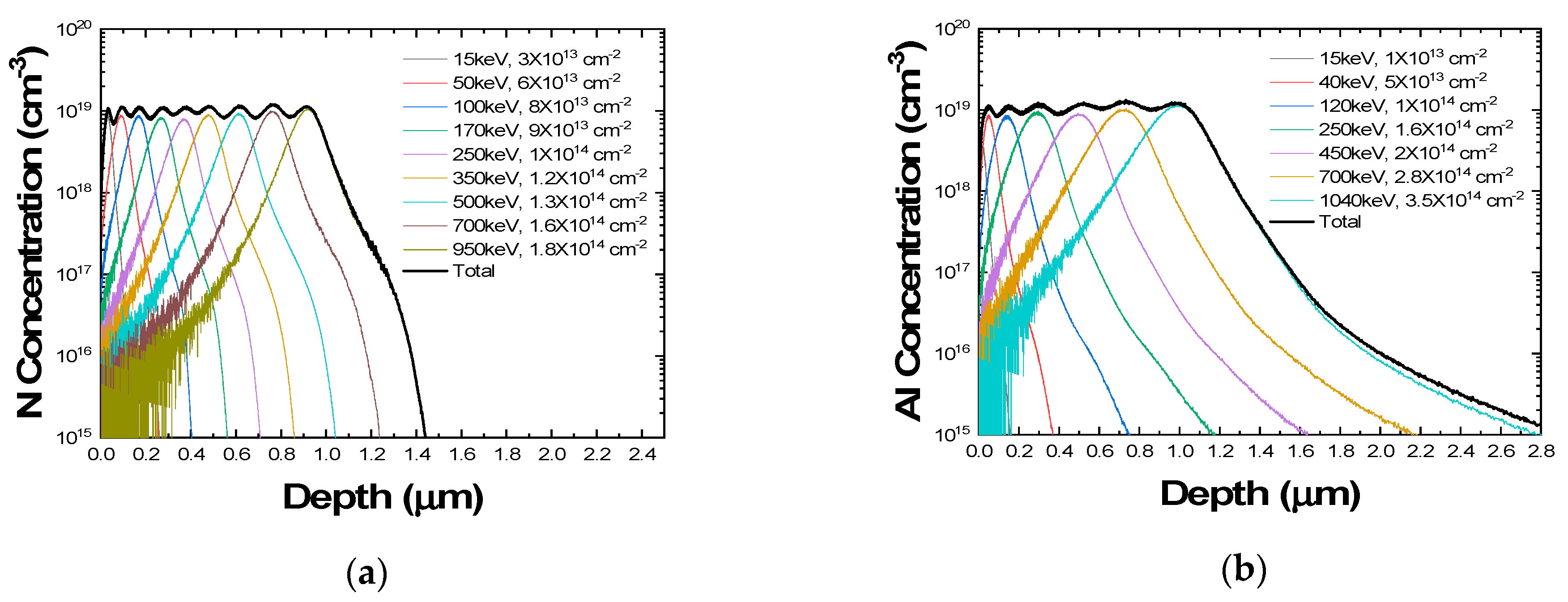
The 4H-SiC thyristor was designed on the N+ substrate because it is difficult to dope a P+ substrate highly with current technology. The epitaxy can be used to grow a P+ anode/N base/low-doped P-drift region/P buffer on N+ substrate. The drift layer sustained the breakdown. The doping concentration of P buffer was generally higher than that of the P-drift so that it determined the electric field distribution of the reverse-biased P-drift/P buffer/N+ cathode junction. The P buffer also increased recombination at the NPN BJT base. The N+ gate can be fabricated using ion implantation and activation after mesa etching. It is noted that our device was asymmetric. Figure 2 shows simulated depth profiles of the ion implantation for N+ and P+ junctions with various energies and doses. We used the Monte Carlo method of the Silvaco Athena tool [30]. For each N+ and P+ profiles, nitrogen and aluminum were used with 4° tilt. The both profiles were designed for target concentration of 1019 cm−3 and depth of 1 μm, respectively.
The distance between the P+ anode and N+ gate, lspace, was optimized at 10 μm, as a built-in potential cannot be established between the P+ anode (emitter) and N base of a PNP BJT if lspace is short. The parameters tdrift and Ndrift represent the thickness and doping concentration of the P-drift region, respectively. The P+ anode and N+ gate were both 1-μm-long. The thickness and junction depth of the P+ anode and N+ gate were 2.5 and 1.0 μm, respectively. An ohmic contact was formed by doping the P+ anode, N+ gate, and N+ cathode to a concentration of 1019 cm−3. The N base of the P-drift region was fabricated with a doping concentration of 7 × 1016 cm−3 to a depth of 2.5 μm. The doping concentration of the P buffer below the P-drift region was 3 × 1016 cm−3 to a thickness of 2.5 μm. Finally, the pulsing gate current was used to turn on the PNP BJT, and to trigger the regenerative action of the thyristor.
Atlas TCAD software (Silvaco) was used for the numerical simulation [30]. The numerical simulation environment is critical for the generation of accurate results with reasonable calculation times. Several physical models of analytic concentration-dependent mobility (ANALYTIC) [31,32], field-dependent mobility (FLDMOB) [33], Shockley–Read–Hall recombination (SRH) [34,35], Auger recombination (AUGER) [36], and band gap narrowing (BGN) [37] were used in this work. These models can be used to calculate the field, doping concentration, and temperature-dependent mobility and current. The lifetime of electrons and holes in the P-drift region was 10−7 s, respectively, and a resolution of 128-bit was selected for precise simulation. The numerical models did not converge easily owing to the negative resistance region of the thyristor. Therefore, an automatic curve tracing algorithm (CURVETRACE) was used to ensure convergence and determine the snapback mechanism of the 4H-SiC thyristor [38]; the algorithm was based on a dynamic load-line technique, in which the boundary conditions were adapted as the process progressed. The algorithm switched automatically from voltage to current boundary conditions, and vice versa. The snapback effect was only observed with the assistance of this algorithm.

3. Results

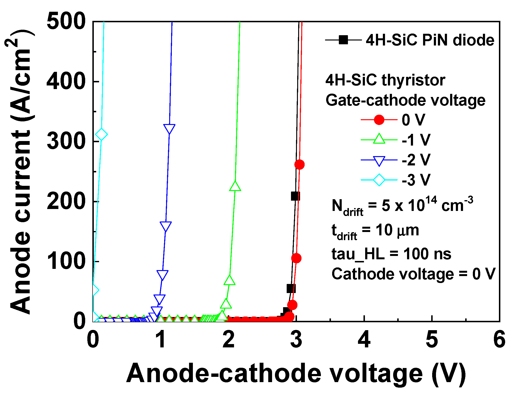
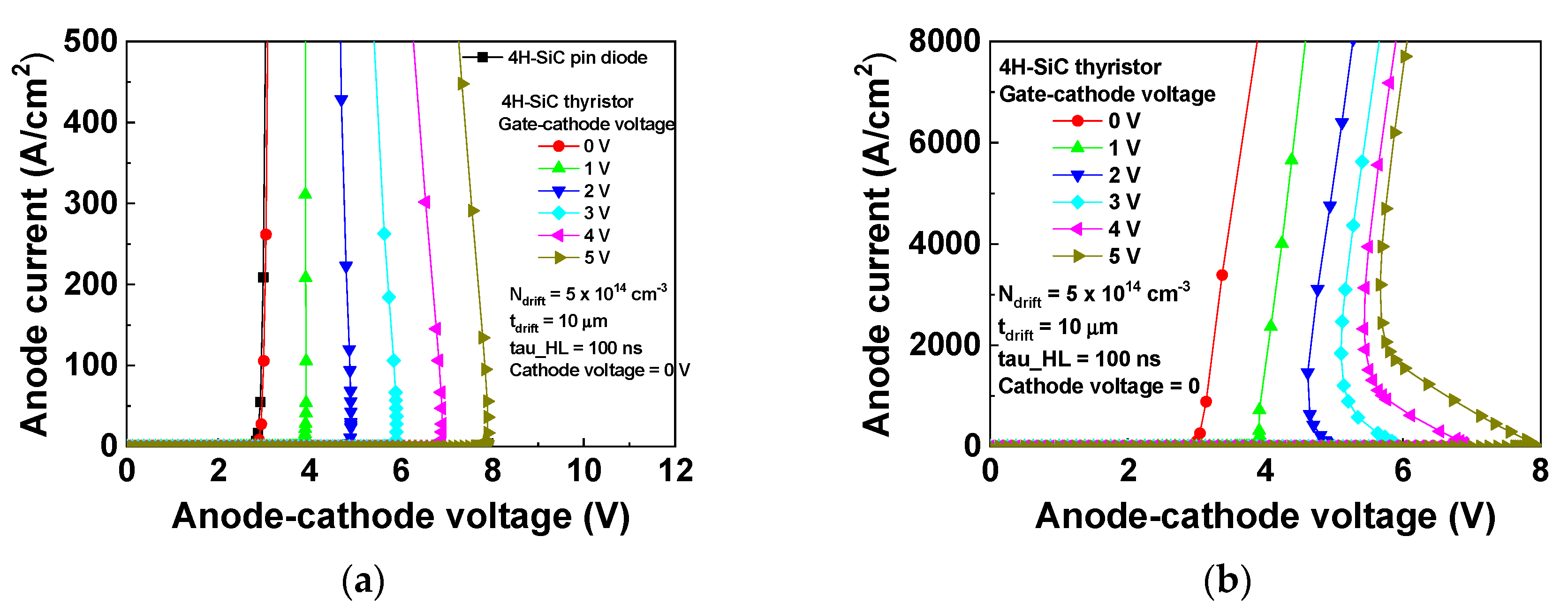
The electrical characteristics of the 4H-SiC thyristor were investigated. The anode voltage was swept in the positive direction after the gate voltage was incremented to a target value. The cathode voltage was zero. The snapback of the thyristor was defined as the anode voltage at which the resistance of the I–V characteristics changed from a positive value to a negative one. Figure 3 shows the simulated anode current of the 4H-SiC thyristor as the gate voltage was varied from 0 to −3 V. The concentration, Ndrift, was 5 × 1014 cm−3 and the thickness, tdrift, was 10 μm. The current-voltage characteristics of the 4H-SiC pin diode formed at the P+ anode/P-drift/P buffer/N+ cathode junctions were also included. The doping concentration and geometry of the pin diode and thyristor were the same when the N base, N+ gate, and gate were not considered in the pin diode. Lower gate voltage resulted in a forward-biased P+ anode/N+ gate junction at lower anode voltage. Therefore, as the gate voltages decreased from 0 to −3 V, the anode current-anode voltage characteristics shifted in the negative direction. The thyristor Vf at 100 A cm−2 were 2.99, 2.05, 1.05, and 0.06 V at the gate voltages of 0, −1, −2, and −3 V, respectively. We also increased the gate voltage from 0 to 5 V as shown in Figure 4. The snapback was clearly seen in the anode current-voltage characteristics under the high current-density scale. When the gate voltage increased from 0 to 5 V, the anode current-voltage characteristics shifted in the positive direction. The thyristor snapback voltage for gate voltages of 0, 1, 2, 3, 4, and 5 V was 2.9, 3.9, 4.9, 5.9, 6.9, and 7.9 V, respectively. The gate voltage determined the PNP BJT base voltage, and the BJT could be turned on with the low gate voltage. The high gate current from P+ anode to N+ gate enhanced the regenerative action of the thyristor. This also decreased the thyristor Vf. We also considered the built-in potential of the PN junction. The Si and 4H-SiC PN junction potential was approximately 0.7 and 3 V, respectively, because the band gap of Si and 4H-SiC is 1.12 and 3.26 eV, respectively.
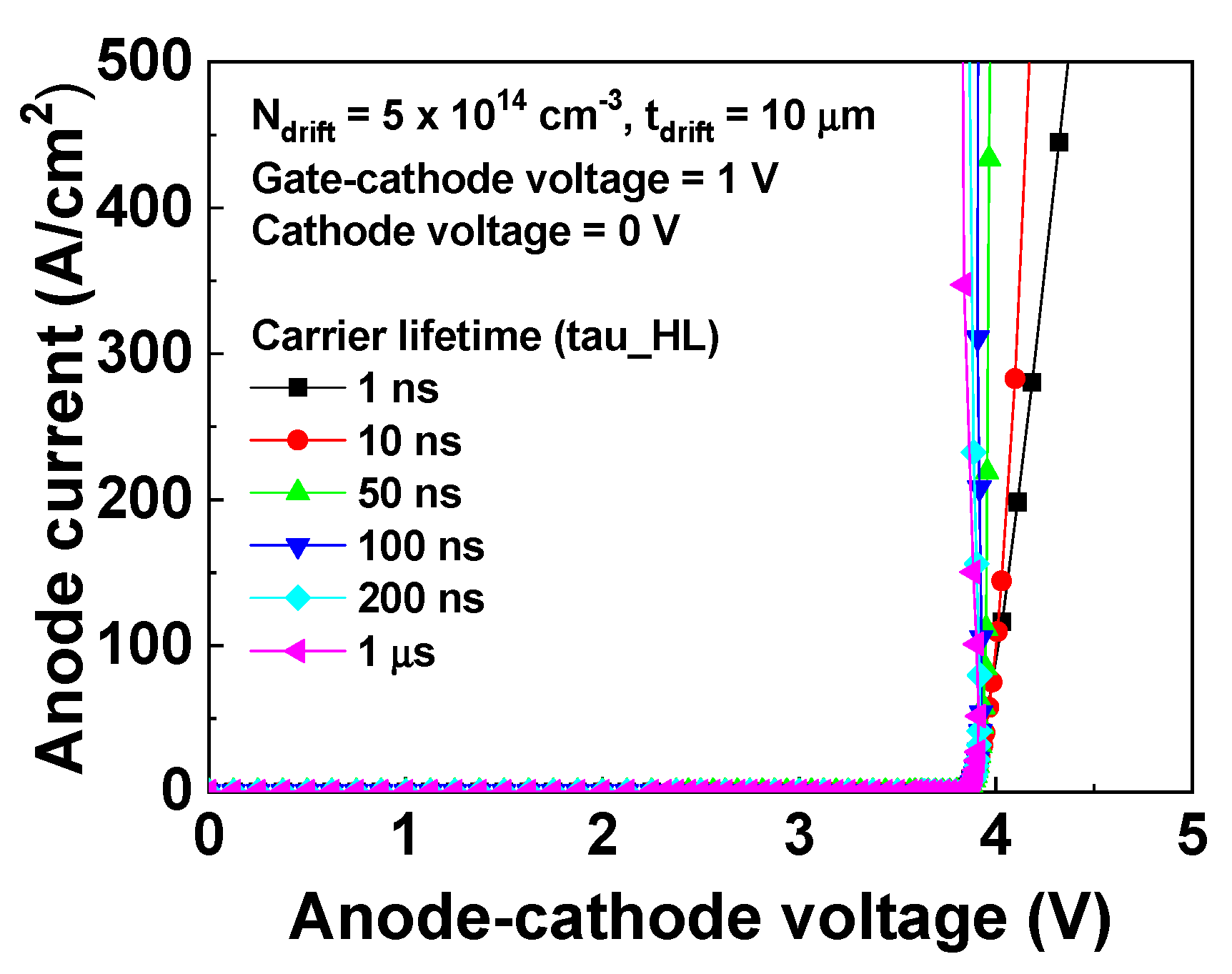
The carrier lifetime was crucial to the thyristors for conductivity modulation during on-state. The forward anode current of the 4H-SiC thyristor with the carrier lifetime from 10−9 to 10−6 s is shown in Figure 5. The increase of the carrier lifetime increased the on current due to the enhanced conductivity modulation. We also compared the forward I–V characteristics with or without incomplete ionization [39]. As expected, the incomplete ionization model (INCOMPLETE) lowered the doping concentration and increased the Vf at 200 A cm−2 from 3.92 to 3.99 V at 300 K.

4. Discussion

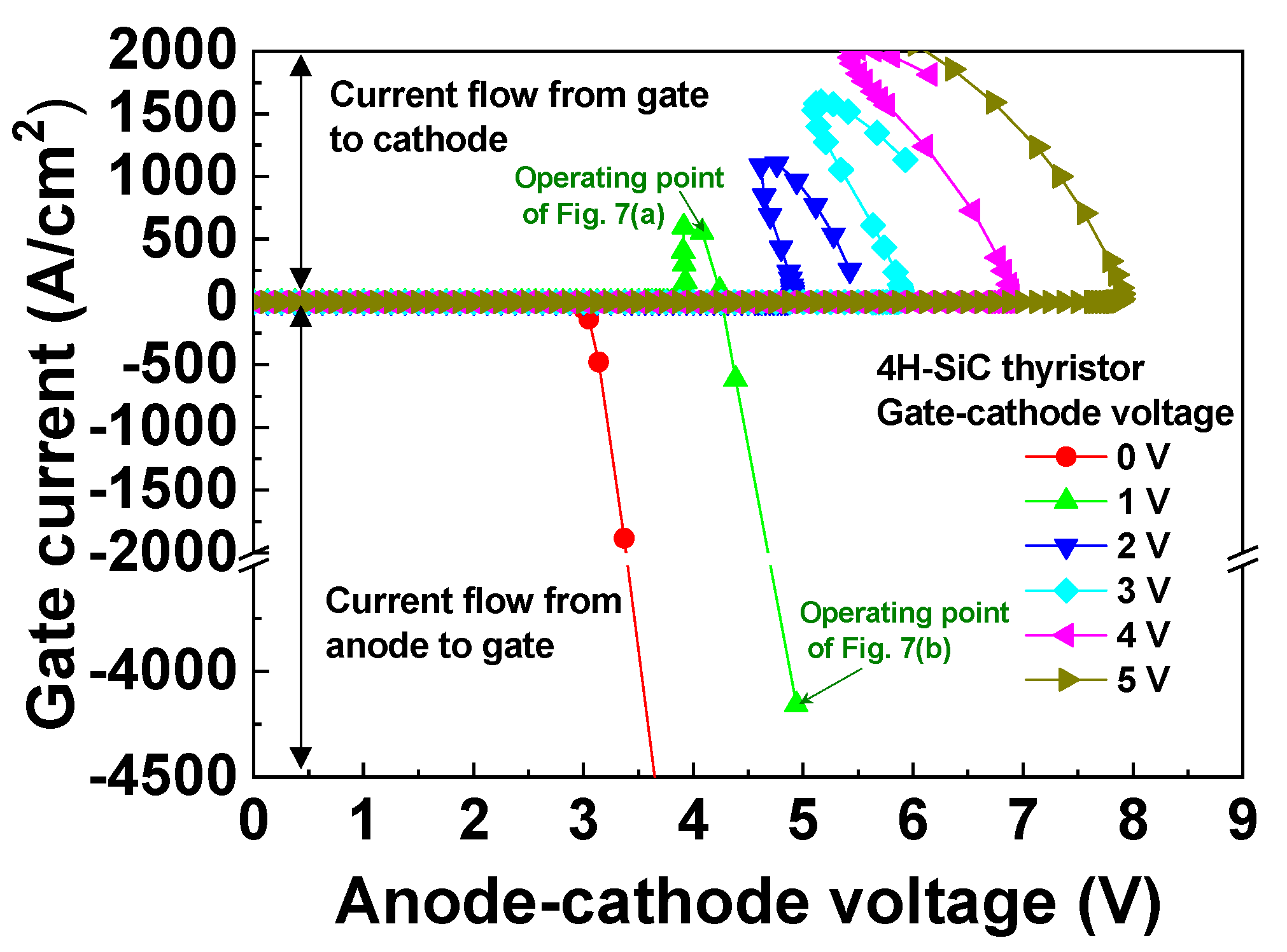
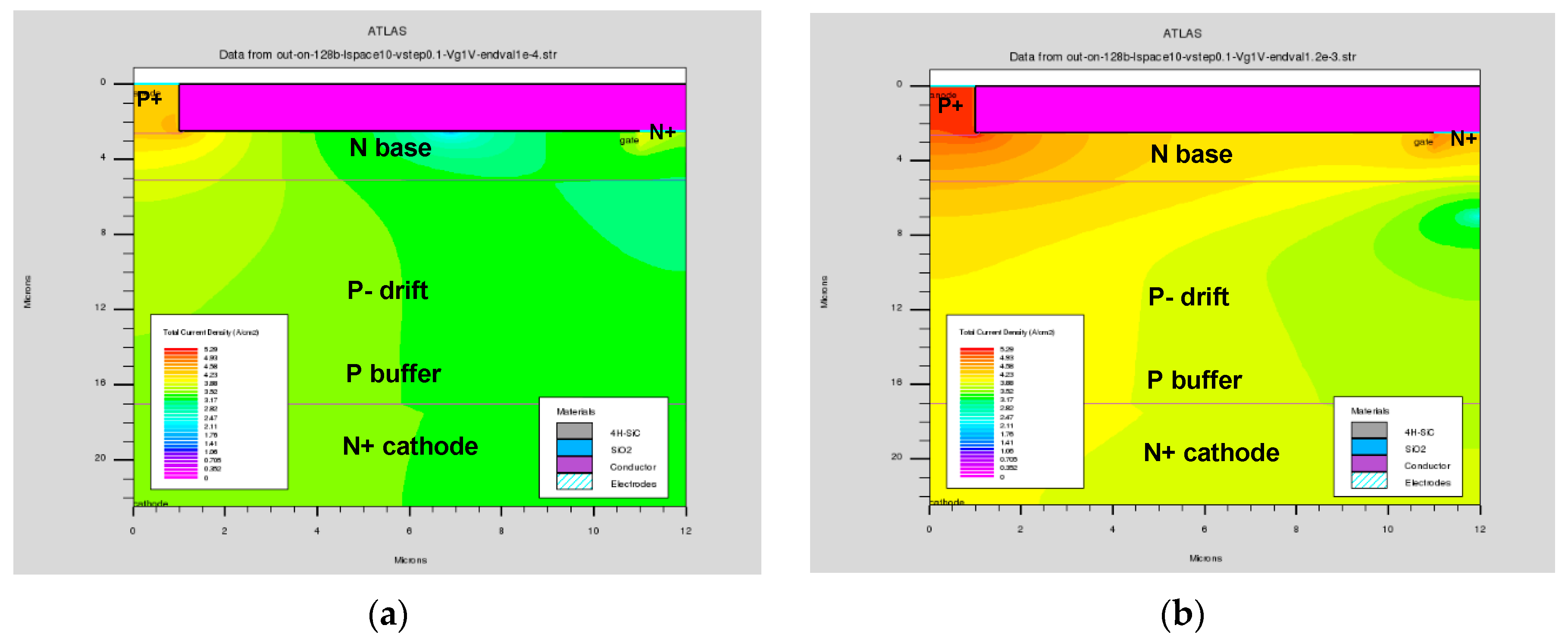
The gate current-anode voltage characteristics include the on-state current flow when a pulsed gate current is used to turn on the device. Figure 6 shows the simulated gate current of the 4H-SiC thyristor as the gate voltage was varied from 0 to 5 V. For zero gate voltage, the gate current was negative as the anode voltage was increased, which indicates a significant current from the P+ anode to the N+ gate to bring the thyristor into conduction mode. In contrast, a positive gate current represents carrier injection from the N+ gate to the P-drift region of the NPN BJT. This current indicates that the positive gate voltage prevents triggering the regenerative action of the thyristor. The decrease in the gate current from the P+ anode to the N+ gate increased both the snapback voltage and Vf. The current flow was verified, as shown in Figure 7. The scale colors indicate the total current density in logarithmic scale. The two operating points of Figure 7 are also included in the gate current-anode voltage characteristics shown in Figure 6. A 1 V bias was applied to the device gate, and a vertical current flow was observed from gate to cathode for an anode bias of 4.08 V, as shown in Figure 7a. The lateral current flow from anode to gate for a 4.94 V anode bias is shown in Figure 7b.
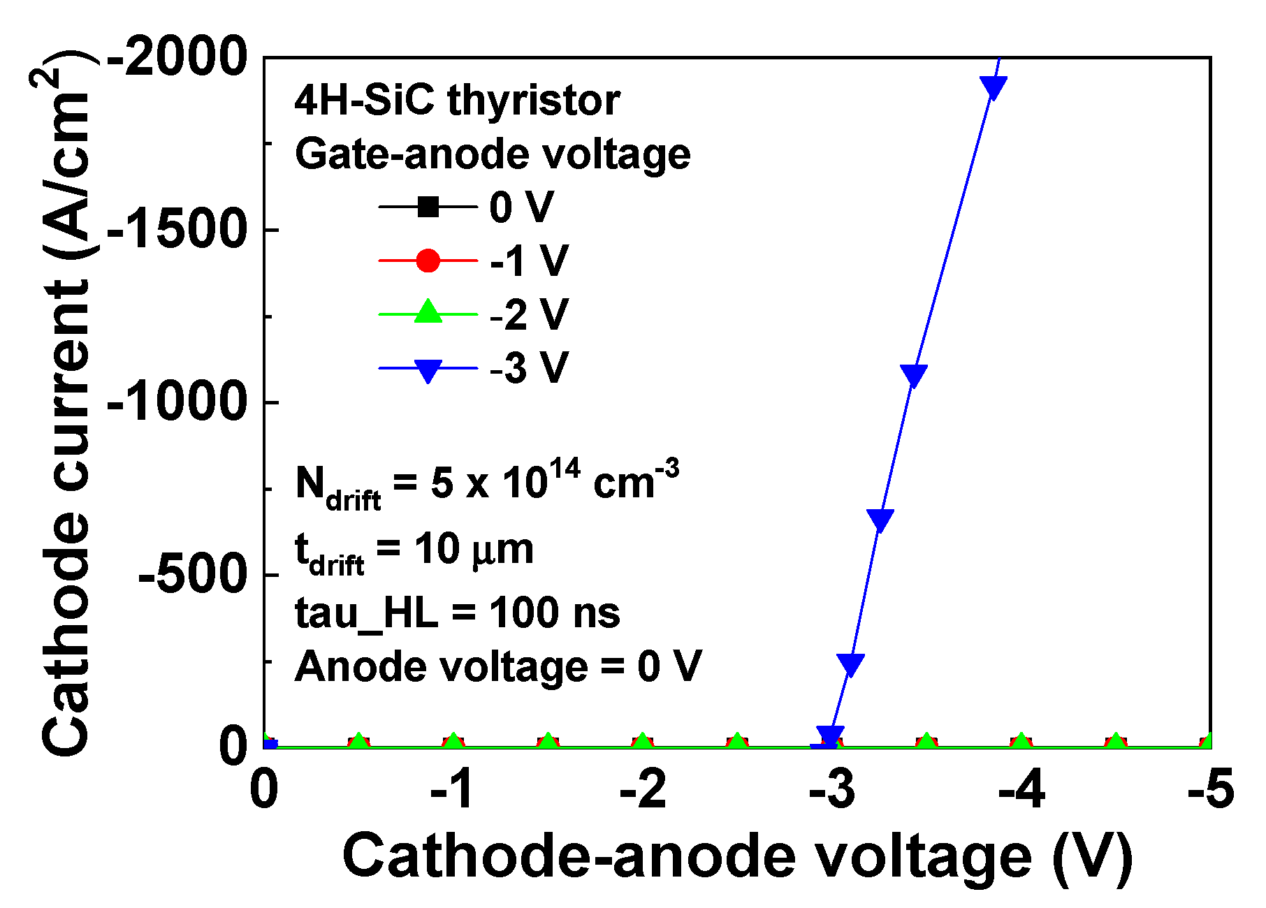
We also simulated the cathode current-cathode voltage characteristics as shown in Figure 8. The cathode voltage was swept in the negative direction after the gate voltage was changed to a target value. The anode voltage was zero. The gate voltage of −3 V caused the forward biased P+ anode/N+ gate which induced the current drive of the PNP BJT and thyristor, respectively. When the gate voltage was −2, −1, or 0 V, the 4H-SiC thyristor cannot be triggered.
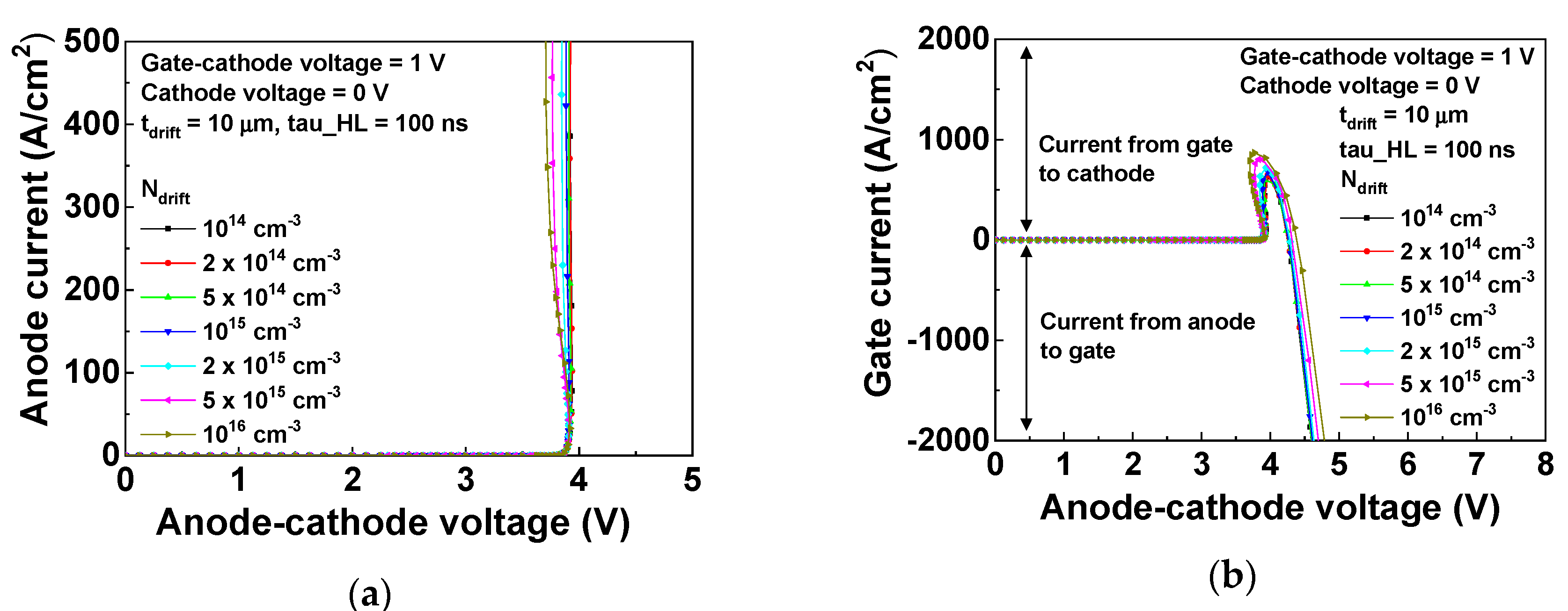
Figure 9 shows the simulated anode and gate current of the 4H-SiC thyristor for several doping concentrations with a 1 V gate bias. The Vf at 100 A cm−2 appeared similar as Ndrift was varied from 1014 to 1016 cm−3. The Vf at 200 A cm−2 as Ndrift was varied, from 1014 to 1015 and 1016 cm−3, was 3.93, 3.90, and 3.79 V, respectively. The increase in Ndrift resulted in an increased forward current and snapback magnitude. In addition, the increase of Ndrift increased recombination at the base, and decreased the NPN BJT current gain. This also decreased the resistance of the P-drift, Rdrift. These two parameters eventually increased the forward current or decreased Vf. The Rdrift had a more significant impact on Vf than current gain of the NPN BJT. The increase in Ndrift decreased the current flow from anode to gate as the decrease in Rdrift enhanced the current flow from anode to cathode.
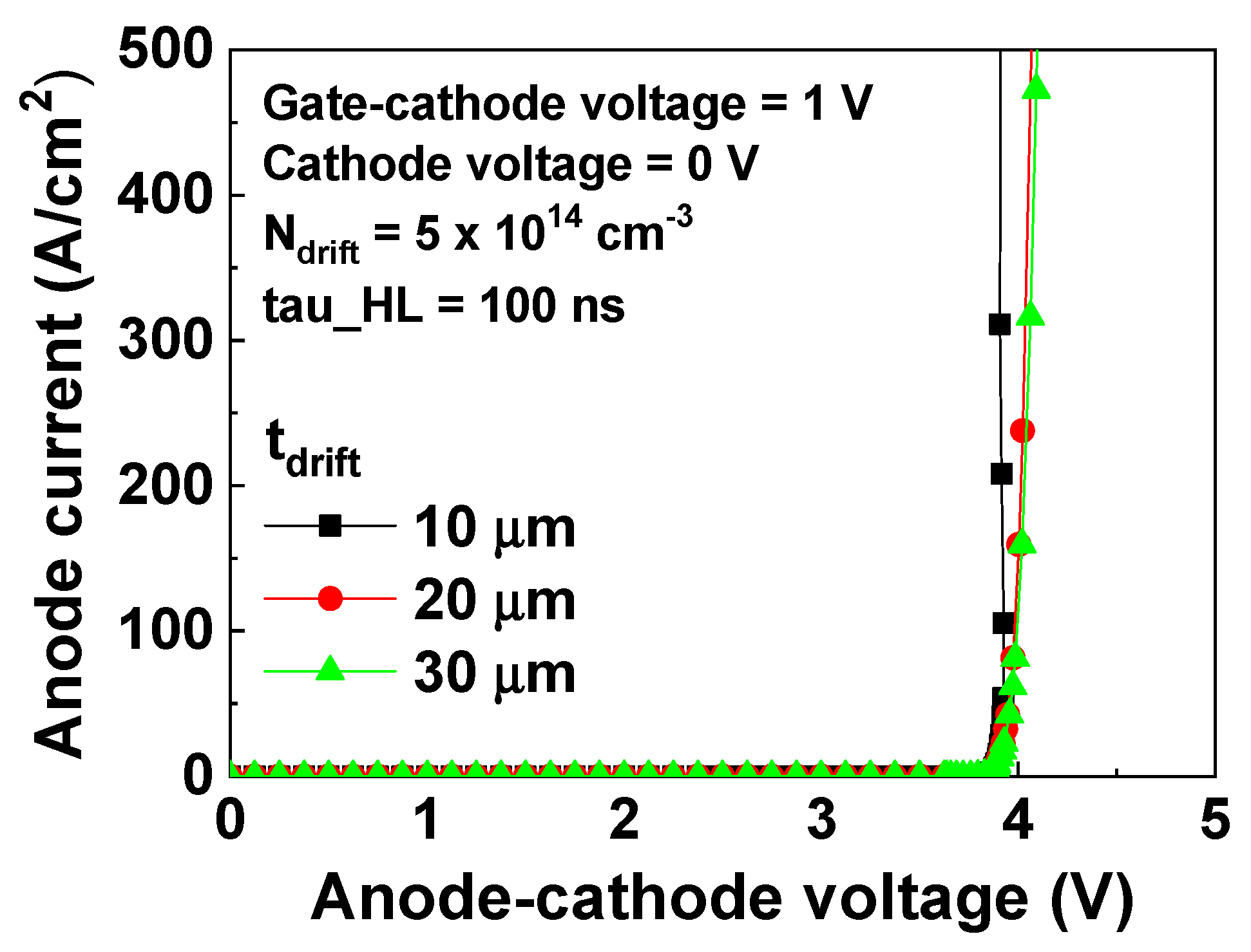
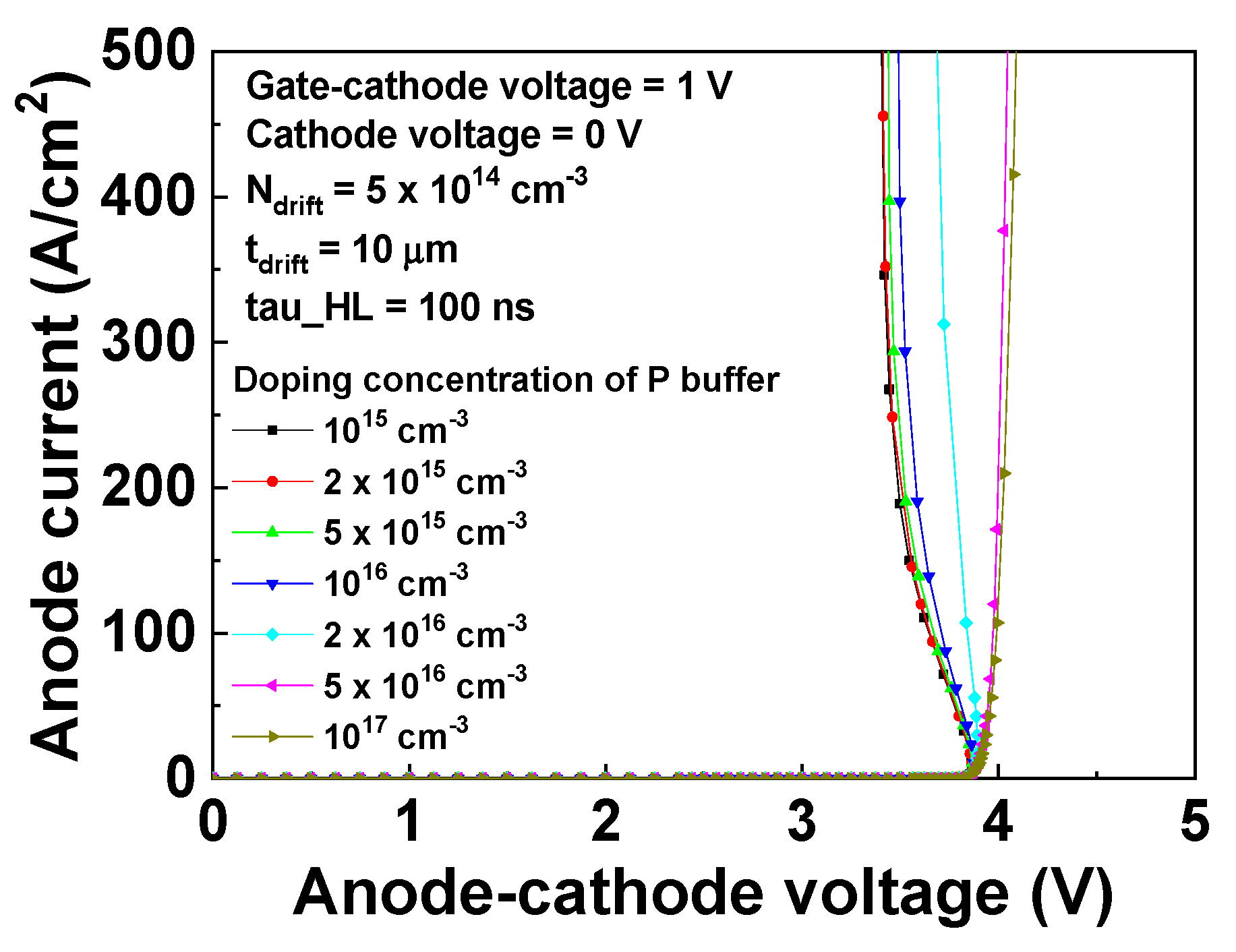
Furthermore, we investigated the anode current of the 4H-SiC thyristor for several tdrift, as shown in Figure 10. Ndrift and gate voltage were fixed at 5 × 1014 cm−3 and 1 V, respectively. The Vf at 200 A cm−2 for tdrift of 10, 20, and 30 μm was 3.92, 4.01, and 4.03 V, respectively. An increase in tdrift can improve the breakdown voltage of the 4H-SiC thyristor, but also results in an increase in Vf. Figure 11 shows the simulated anode current of the 4H-SiC thyristor for various P buffer doping concentrations. When the P buffer doping concentration was 1015, 1016, and 1017 cm−3, the Vf at 100 A cm−2 was 3.65, 3.71, and 3.99 V, respectively. The increase in P buffer doping concentration enhanced recombination at the NPN BJT base and increased Vf. This also affects the electric field distribution under reverse bias, as well as the breakdown voltage and switching speed.
The 4H-SiC thyristor should sustain the breakdown voltage through depletion of the P-drift region. When the anode voltage was greater than the cathode bias, the depletion region at N base/P-drift/P buffer withstood the breakdown voltage. However, when the anode voltage was less than the cathode bias, the depletion region at P-drift/P buffer/N+ cathode withstood the breakdown voltage. For low doping concentrations, the P-drift region was important for breakdown-resistance. The P buffer prevented the punch-through breakdown during forward blocking, but reduced the reverse breakdown voltage. We investigated the P-drift region breakdown voltage using a 4H-SiC pin diode with the P+ anode/P-drift/P buffer/N+ cathode. The anisotropic impact ionization (IMPACT ANISO) 4Hof (0001) 4H-SiC used for calculating breakdown voltage [40]. Due to the long simulation time and the convergence error, we approximated the reverse breakdown voltage of the thyristor to the breakdown voltage of the pin diode.
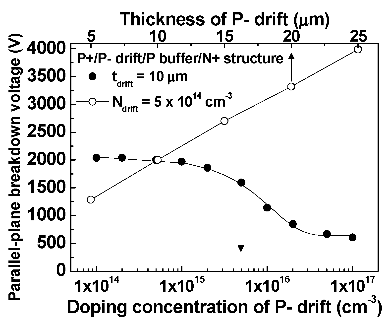
Figure 12 shows the simulated parallel-plane breakdown voltage of the P-drift/P buffer/N+ cathode for several values of Ndrift and tdrift. When the value of tdrift was fixed at 10 μm, the breakdown voltage of the P-drift/P buffer/N+ cathode when Ndrift was 1014, 1015, 1016, and 1017 cm−3 was 2038, 1970, 1143, and 606 V, respectively. If the Ndrift was fixed at 5 × 1014 cm−3, the breakdown voltage for tdrift of 5, 10, 15, 20, and 25 μm was 1289, 2000, 2700, 3320, and 3990 V, respectively. The breakdown voltage increased with decreasing Ndrift and increasing tdrift due to the extended depletion region and the reduced peak value of the electric field. It should be noted that we have determined the one-dimensional breakdown voltage. The two-dimensional (cylindrical) or three-dimensional (spherical) breakdown voltage of the thyristor should be less than the one-dimensional value due to the curvature effect or electric field distribution.

5. Conclusions

Numerical simulation was used to design a P+ anode/N base/P-drift/P buffer/N+ cathode 4H-SiC thyristor on the N+ substrate. The 4H-SiC thyristor gate current was analyzed when a gate current pulse was applied during the turn-on process. The base-emitter current of the PNP BJT was important to activate the regenerative action of the thyristor which was adjusted by the gate potential. The decrease of the gate current from P+ anode to N+ gate prevented turning on the thyristor by increasing snapback voltage. The increase in Ndrift decreased Rdrift and Vf. An increase in the P buffer doping concentration increased Vf due to the increase in recombination at the NPN BJT base. The breakdown voltage of the P-drift/P buffer/N+ cathode when Ndrift was 1014, 1015, 1016, and 1017 cm−3 was 2038, 1970, 1143, and 606 V, respectively. 4H-SiC thyristors with high on-current are suitable for power applications such as high-voltage DC transmission, traction, and megawatt drive systems.

Author Contributions

Conceptualization and investigation for the numerical design, and writing—original draft preparation, H.L. and M.-W.H.; the formal analysis and visualization of the electrical characteristics, T.K.; the Monte Carlo simulation and writing—review, O.S. All authors have read and agreed to the published version of the manuscript.

Funding

This research was supported by Korea Electric Power Corporation (Grant number: R18XA01). This research was also supported by the KERI Primary research program of MSIT/NST (No. 19-12-N0101-48).

Conflicts of Interest

The authors declare no conflict of interest.

References

  1. Huang, A.Q. Power semiconductor devices for smart grid and renewable energy systems. Proc. IEEE 2017, 105, 2019–2047. [Google Scholar] [CrossRef]
  2. Choi, U.-M.; Blaabjerg, F.; Lee, K.-B. Study and handling methods of power IGBT module failures in power electronic converter systems. IEEE Trans. Power Electron. 2015, 30, 2517–2533. [Google Scholar] [CrossRef]
  3. Vobecký, J.; Schulze, H.-J.; Streit, P.; Niedernostheide, F.-J.; Botan, V.; Przybilla, J.; Kellner-Werdehausen, U.; Bellini, M. Silicon thyristors for ultrahigh power (GW) applications. IEEE Trans. Electron Devices 2017, 64, 760–768. [Google Scholar] [CrossRef]
  4. Liu, G.; Tuttle, B.R.; Dhar, S. Silicon carbide: A unique platform for metal-oxide-semiconductor physics. Appl. Phys. Rev. 2015, 2, 021307. [Google Scholar] [CrossRef]
  5. She, X.; Huang, A.Q.; Lucía, Ó.; Ozpineci, B. Review of silicon carbide power devices and their applications. IEEE Trans. Ind. Electron. 2017, 64, 8193–8205. [Google Scholar] [CrossRef]
  6. Kimoto, T.; Yonezawa, Y. Current status and perspectives of ultrahigh-voltage SiC power devices. Mater. Sci. Semicon. Proc. 2018, 78, 43–56. [Google Scholar] [CrossRef]
  7. Kimoto, T. Material science and device physics in SiC technology for high-voltage power devices. Jpn. J. Appl. Phys. 2015, 54, 040103. [Google Scholar] [CrossRef]
  8. Lee, S.; Kim, S.; Kang, H.J.; Kim, H.W.; Seok, O.; Moon, J.H.; Bahng, W.; Kim, H.J.; Ha, M.W. Effect of sweeping direction on the capacitance−voltage behavior of sputtered SiO2/4H-SiC metal-oxide semiconductors after nitric oxide post-deposition annealing. Phys. Scr. 2019, 94, 125811. [Google Scholar] [CrossRef]
  9. Lee, S.; Kim, Y.S.; Kang, H.J.; Kim, H.; Ha, M.W.; Kim, H.J. Effects of post-deposition annealing on sputtered SiO2/4H-SiC metal-oxide-semiconductor. Solid-State Electron. 2018, 139, 115–120. [Google Scholar] [CrossRef]
  10. Seok, O.; Kim, H.W.; Moon, J.H.; Bahng, W. High-voltage LDIMOSFETs on HPSI 4H-SiC substrate with dual field plates. Phys. Scr. 2019, 94, 76–96. [Google Scholar] [CrossRef]
  11. Asllani, B.; Morel, H.; Phung, L.V.; Planson, D. 10 kV silicon carbide pin diodes—from design to packaged component characterization. Energies 2019, 12, 4566. [Google Scholar] [CrossRef] [Green Version]
  12. Kimoto, T.; Yamada, K.; Niwa, H.; Suda, J. Promise and challenges of high-voltage SiC bipolar power devices. Energies 2016, 9, 908. [Google Scholar] [CrossRef] [Green Version]
  13. Qin, H.; Mo, Y.; Xun, Q.; Zhang, Y.; Dong, Y. A digital-controlled SiC-based solid state circuit breaker with soft switch-off method for DC power system. Electronics 2019, 8, 837. [Google Scholar] [CrossRef] [Green Version]
  14. Xu, C.; Ma, Q.; Xu, P.; Cui, T. Shaping SiC MOSFET voltage and current transitions by intelligent control for reduced EMI generation. Electronics 2019, 8, 508. [Google Scholar] [CrossRef] [Green Version]
  15. Tiku, D. dc power transmission. IEEE Power Energy Mag. 2014, 12, 76–96. [Google Scholar] [CrossRef]
  16. Veilleux, E.; Ooi, B.T. Multiterminal HVDC with thyristor power-flow controller. IEEE Trans. Power Del. 2012, 27, 1205–1212. [Google Scholar] [CrossRef]
  17. Kim, C.K.; Sood, V.K.; Jang, G.S.; Lim, S.J.; Lee, S.J. HVDC Transmission: Power Conversion Applications in Power Systems; John Wiley & Sons, Inc.: Hoboken, NJ, USA, 2009; pp. 149–159. [Google Scholar]
  18. Shah, P.B.; Jones, K.A. Simulated Turn-Off of 4H-SiC gate turn-off thyristors with gate electrodes on the p-base or the n-base. IEEE Electron Device Lett. 1999, 20, 577–579. [Google Scholar] [CrossRef] [Green Version]
  19. Huang, A.Q.; Zhang, B. Comparing SiC switching power devices: MOSFET, NPN transistor and GTO thyristor. Solid-State Electron. 2000, 44, 325–340. [Google Scholar] [CrossRef]
  20. Cao, L.; Li, B.; Zhao, J.H. Characterization of 4H-SiC gate turn-off thyristor. Solid-State Electron. 2000, 44, 347–352. [Google Scholar] [CrossRef]
  21. Li, Y.; Huang, A.Q.; Motto, K. Experimental and numerical study of the emitter turn-off thyristor (ETO). IEEE Trans. Power Electron. 2000, 15, 561–574. [Google Scholar] [CrossRef]
  22. Wang, J.; Huang, A.Q. Design and characterization of high-voltage silicon carbide emitter turn-off thyristor. IEEE Trans. Power Electron. 2009, 24, 1189–1197. [Google Scholar] [CrossRef]
  23. Song, X.; Huang, A.Q.; Lee, M.; Peng, C.; Cheng, L.; O’Brien, H.; Ogunniyi, A.; Scozzie, C.; Palmour, J. 22 kV SiC emitter turn-off (ETO) thyristor and its dynamic performance including SOA. In Proceedings of the 27th International Symposium Power Semiconductor Devices & ICs, Hong Kong, China, 10–14 May 2015; pp. 277–280. [Google Scholar]
  24. Song, X.; Huang, A.Q.; Lee, M.C.; Peng, C. Theoretical and Experimental Study of 22 kV SiC Emitter Turn-OFF (ETO) Thyristor. IEEE Trans. Power Electron. 2017, 32, 6381–6393. [Google Scholar] [CrossRef]
  25. Sugawara, Y.; Takayama, D.; Asano, K.; Agarwal, A.K.; Ryn, S.; Palmour, J.; Ogate, S. 12.7kV ultra high voltage SiC commutated gate turn-off thyristor: SICGT. In Proceedings of the 16th International Symposium Power Semiconductor Devices & ICs, Kitakyushu, Japan, 24–27 May 2004; pp. 365–368. [Google Scholar]
  26. Agarwal, A.K.; Damsky, B.; Richmond, J.; Krishnaswami, S.; Capell, C.; Ryu, S.H.; Palmour, J.W. The first demonstration of the 1 cm × 1 cm SiC thyristor chip. In Proceedings of the 17th International Symposium Power Semiconductor Devices & ICs, Santa Babara, CA, USA, 23–26 May 2005; pp. 159–162. [Google Scholar]
  27. Zhou, C.N.; Yue, R.F.; Wang, Y.; Zhang, J.; Dai, G.; Li, J.T. 10-kV 4H-SiC gate turn-off thyristors with space-modulated buffer trench three-step JTE. IEEE Electron Device Lett. 2018, 39, 1199–1202. [Google Scholar] [CrossRef]
  28. Li, Z.; Zhou, K.; Zhang, L.; Xu, X.; Li, L.; Li, J.; Dai, G. A simple multistep etched termination technique for 4H-SiC GTO thyristors. Solid-State Electron. 2019, 151, 1–5. [Google Scholar] [CrossRef]
  29. Sung, W.; Huang, A.Q.; Baliga, B.J. Bevel junction termination extension-a new edge termination technique for 4H-SiC high-voltage devices. IEEE Electron Device Lett. 2015, 36, 594–596. [Google Scholar] [CrossRef]
  30. Atlas and Athena User’s Manual; Silvaco International: Santa Clara, CA, USA, 2009.
  31. Klaassen, D.B.M. A unified mobility model for device simulation-I. Model equations and concentration dependence. Solid-State Electron. 1992, 35, 953–959. [Google Scholar] [CrossRef]
  32. Klaassen, D.B.M. A unified mobility model for device simulation-II. Temperature dependence of carrier mobility and lifetime. Solid-State Electron. 1992, 35, 961–967. [Google Scholar] [CrossRef]
  33. Zakhleniuk, N.A. Nonequilibrium drift-diffusion transport in semiconductors in presence of strong inhomogeneous electric fields. Appl. Phys. Lett. 2006, 89, 252112. [Google Scholar] [CrossRef]
  34. Shockley, W.; Read, W.T. Statistics of the recombinations of holes and electrons. Phys. Rev. 1952, 87, 835–842. [Google Scholar] [CrossRef]
  35. Hall, R.N. Electron-hole recombination in germanium. Phys. Rev. 1952, 87, 387. [Google Scholar] [CrossRef]
  36. Dziewior, J.; Schmid, W. Auger coefficients for highly doped and highly excited silicon. Appl. Phys. Lett. 1977, 31, 346–348. [Google Scholar] [CrossRef]
  37. Slotboom, J.W.; de Graaf, H.C. Measurements of bandgap narrowing in Si bipolar transistors. Solid-State Electron. 1976, 19, 857–862. [Google Scholar] [CrossRef]
  38. Goossens, R.J.G.; Beebe, S.; Yu, Z.; Dutton, R.W. An automatic biasing scheme for tracing arbitrarily shaped I-V curves. IEEE Trans. Comput.-Aided Des. Integr. Circuits Syst. 1994, 13, 310–317. [Google Scholar] [CrossRef]
  39. Hakakeyma, T.; Fukuda, K.; Okumura, H. Physical models for SiC and their application to device simulations of SiC insulated-gate bipolar transistors. IEEE Trans. Electron Devices. 2013, 60, 613–621. [Google Scholar] [CrossRef]
  40. Hatakeyama, T.; Nishio, J.; Ota, C.; Shinohe, T. Physical modeling and scaling properties of 4H-SiC power devices. In Proceedings of the International Conference Simulation Semiconductor Processes and Devices, Tokyo, Japan, 1–3 September 2005; pp. 171–174. [Google Scholar]
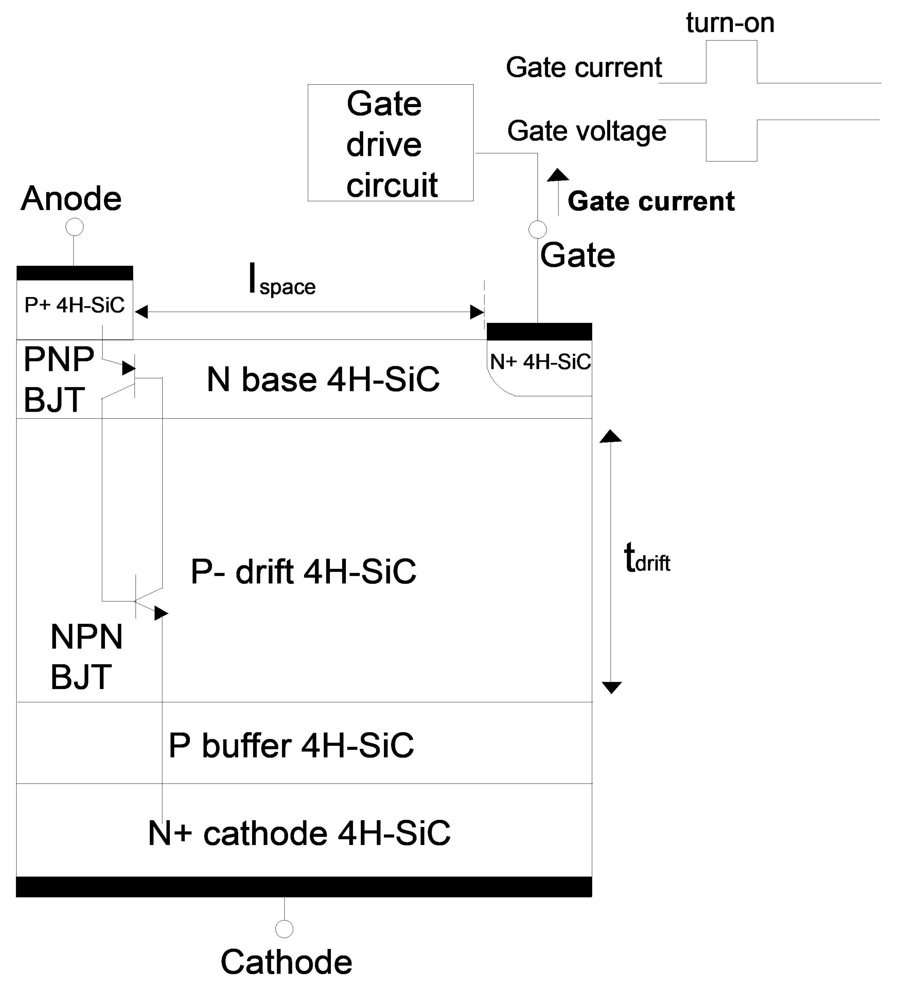
Figure 1. Cross-section of the 4H-SiC thyristor.
Electronics 09 00332 g001
Figure 2. Simulated depth profiles of (a) nitrogen for N+ junction and (b) aluminum for P+ junction
Electronics 09 00332 g002
Figure 3. Simulated anode current of the 4H-SiC thyristor for various gate-cathode voltages from 0 to −3 V. The doping concentration (Ndrift), thickness (tdrift), and high-level injection carrier lifetime (tau_HL) were 5 × 1014 cm−3, 10 μm, and 10−7 s, respectively.
Electronics 09 00332 g003
Figure 4. Simulated anode current of the 4H-SiC thyristor for various gate-cathode voltages from 0 to 5 V. The current range was (a) 0–500 and (b) 0–8000 A/cm2, respectively. The doping concentration (Ndrift), thickness (tdrift), and high-level injection carrier lifetime (tau_HL) were 5 × 1014 cm−3, 10 μm, and 10−7 s, respectively.
Electronics 09 00332 g004
Figure 5. Simulated anode current of the 4H-SiC thyristor for various high-level injection carrier lifetime (tau_HL) from 10−9 to 10−6 s. The doping concentration (Ndrift), thickness (tdrift), and gate-cathode voltage were 5 × 1014 cm−3, 10 μm, and 1 V, respectively.
Electronics 09 00332 g005
Figure 6. Simulated gate current of the 4H-SiC thyristor for various gate-cathode voltages from 0 to 5 V. The doping concentration (Ndrift), thickness (tdrift), and high-level injection carrier lifetime (tau_HL) were 5 × 1014 cm−3, 10 μm, and 10−7 s, respectively.
Electronics 09 00332 g006
Figure 7. Simulated current flow in logarithmic scale (a) from the gate to cathode for a 4.08 V anode bias, and (b) from anode to gate for a 4.94 V anode potential. The doping concentration (Ndrift), thickness (tdrift), gate-cathode voltage, and high-level injection carrier lifetime (tau_HL) were 5 × 1014 cm−3, 10 μm, 1 V, and 10−7 s respectively.
Electronics 09 00332 g007
Figure 8. Simulated cathode current-cathode voltage characteristics of the 4H-SiC thyristor for various gate-anode voltages from 0 to –3 V. The anode voltage was zero. The doping concentration (Ndrift), and high-level injection carrier lifetime (tau_HL) were 5 × 1014 cm−3, and 10−7 s, respectively.
Electronics 09 00332 g008
Figure 9. Simulated (a) anode current and (b) gate current of the 4H-SiC thyristor for various P-drift (Ndrift) doping concentrations. The thickness of the P-drift region (tdrift), gate-cathode voltage, and high-level injection carrier lifetime (tau_HL) were 10 μm, 1 V, and 10−7 s, respectively.
Electronics 09 00332 g009
Figure 10. Simulated anode current of the 4H-SiC thyristor for various thickness of P-drift region (tdrift). The doping concentration (Ndrift), gate-cathode voltage, and high-level injection carrier lifetime (tau_HL) were 5 × 1014 cm−3, 1 V, and 10−7 s, respectively.
Electronics 09 00332 g010
Figure 11. Simulated anode current of the 4H-SiC thyristor for various P buffer doping concentrations. The doping concentration (Ndrift), thickness (tdrift), gate-cathode voltage, and high-level injection carrier lifetime (tau_HL) were 5 × 1015 cm−3, 10 μm, 1 V, and 10−7 s, respectively.
Electronics 09 00332 g011
Figure 12. Simulated parallel-plane breakdown voltage of P-drift/P buffer/N+ cathode for several P-drift doping concentrations (Ndrift) and thicknesses (tdrift). The doping concentration of the P buffer was 3 × 1016 cm−3.
Electronics 09 00332 g012