Abstract
As the application of low-voltage-direct-current system increases, fault analysis in the low-voltage-direct-current system has essential because the fault response has different from the conventional AC distribution system. Especially, the fault current by the discharge current of the capacitor in the low-voltage-direct-current distribution system has very large compared with the conventional AC distribution system. Therefore, this paper proposed the application of the superconducting fault current limiter for limiting the fault current on the low-voltage-direct-current system. As one of the protected methods against fault current, the superconducting fault current limiter which could quickly limit the fault current has been noticed as an attractive method. However, the protection relay may malfunction such as over current relay, selective protection relay due to limiting fault current by applying superconducting fault current limiter. Therefore, in this paper proposed a solution to malfunction problem of the protection relay using the voltage components of the high temperature superconductivity. This paper verified the effect of the proposed method through test modelling and PSCAD/EMTDC.
1. Introduction
Micro grid has been in the spotlight for the efficient operation of distribution generation such as photovoltaic (PV) and energy storage systems (ESS) and for improving the reliability of the system. The low voltage direct current (LVDC) system for the efficient topology of the micro-grid is being used to meet the lofty goal of sharing distribution generation [1,2].
As the LVDC system has a different configuration from the AC system, the analysis of fault response should be necessary for protecting the system component. In particular, the LVDC system has a fatal problem in which the fault current sharply increased due to the discharge current of the capacitor [3,4]. Therefore, many studies have been conducted to limit the fault current on the LVDC system.
First of all, to understand the fault characteristics of the LVDC system, many studies focus on the fault response [5,6,7]. Also, since the LVDC system did not exist zero crossings, other studies have been conducted on the DC circuit breaker or insulated gate bipolar transistor (IGBT) isolation switches [3,8,9,10]. Reference [11] analysed the stability of applying a circuit breaker using a superconducting fault current limiter (SFCL) for protecting a DC system. However, for economic or bulky structure reasons, the DC circuit breaker was difficult to install on the LVDC system. Therefore, methods for limiting fault current have been studied. In order to limit the fault current, conventional methods were analysed by increasing the line impedance or changing the capacity of the capacitor on the DC-link [12,13,14,15]. However, these methods result in increased line losses or adversely affected the LVDC system. Reference [16] proposed a modular multi-level converter (MMC) based process for limiting fault current in DC systems. However, the MMC based method is not suitable for LVDC system. Reference [17] demonstrated to achieve the self-acting fault current limitation and protect the grid voltage using fault current limiting (FCL) and superconducting cable (SC). References [18,19,20,21] analysed the results of the positioning on the SFCL and its effects on limiting the fault current. The SFCL has more effective than other methods to protect the LVDC system against fault current. Reference [22,23] analysed the fault characteristics and protection of the DC distribution system with SFCL. Reference [24] proposed design method for limiting fault current which is weak point in the DC system. These studies confirmed that the SFCL is an effective method for limiting the fault current on the LVDC system. However, conventional studies only analysed the limiting effect of the fault current by applying SFCL. The problem caused by limiting fault current was not analysed. In order to effectively apply the SFCL to the LVDC system, a solution to solve the problem should be proposed.
This paper proposes the application of the SFCL to limit the fault current on the LVDC system. When the SFCL was applied to the LVDC system for limiting fault current, protection relay such as over current relay and selective protection relay was affected. The over current relay determines the timing of the trip signal according to the magnitude of the fault current. Therefore, as the fault current is limited, the timing of the trip signal on the over current relay is delayed [25,26]. In addition, the selective protection relay considered in this paper is affected because it detects the fault using the pole of the derivative on the fault current [27]. Therefore, this paper analysed the operational characteristics of the protection relay according to limiting the fault current. Also, this paper proposed a solution for the protection relays that have a problem with malfunction or timing delay of the trip signal. The method proposed in this paper solved the malfunction of the over current relay. Also, the selective protection relay improved the performance to detect the fault quickly by using the method proposed in this paper. The effect of the proposed method in this paper was verified by PSCAD/EMTDC.
Section 2 describes the modelling of the LVDC system and the SFCL respectively. Section 3.1 describes the fault response on the LVDC system. Section 3.2 verifies the effect of limiting fault current by applying the SFCL. Section 3.3 and Section 3.4 is analysed the problem caused by limiting fault current and proposed a solution for properly operational characteristics on the protection relay. Section 4 is discuss about this paper. Section 5 is conclusion.
2. Simulation Modelling
2.1. Low Voltage Direct Current (LVDC) System
Section 2.1 describes the modelling of the LVDC system. As shown in Figure 1, the LVDC system has connected to the AC system through the rectifier. Also, the PV system and the DC load have connected in the LVDC system through the DC/DC converter. The voltage of the LVDC system has composed bipolar 750 [V].

Figure 1.
Modelling of low voltage direct current (LVDC) System.
This paper focuses on analysing the trip signal of the protection relay, so the model of the circuit breaker used in Figure 1 could be opened immediately after receiving the trip signal on the protection relay. In this paper, the protection relay for fault detection has consists of the over current relay and selective protection relay which have mainly used in the LVDC system [13,27,28,29].
Table 1 shows the parameters used in the LVDC system modelling in Figure 1. The small-capacity transformer at the front position of the PV and load was not shown in Figure 1. Also, power supply from the AC system to the DC system was not limited by the transformer capacity. The profile of the PV and load did not have a significant effect on the fault analysis because the fault analysis of the DC system was transient (under 0.02 [s]). Table 2 shows the fault scenario for the analysis of the fault response and the operational characteristics of the protection relay in the LVDC system. The fault was simulated by a short-circuit fault between positive-pole and negative-pole. The simulation factors such as measurement time of the protection relay and the operation signal of the circuit breaker are assumed to be ideal.

Table 1.
Parameters of LVDC system.
Table 2.
Fault Scenario.
2.2. Superconducting Fault Current Limiters (SFCL)
Section 2.2 describes the modelling of the SFCL for limiting fault current. Various SFCLs such as resistive-, trigger- and flux lock types have been studied. Among them, the resistive type which consists of the simple component has a fast operation due to only using the characteristics of the high temperature superconductivity (HTSC) elements [30,31]. Fast operation characteristics are a very important issue in the LVDC system. Therefore, the resistive type SFCL was applied in this paper.
The SFCL has zero resistance under normal state. This feature has the advantage that there is no line loss than the method of increasing the line impedance to limit the fault current. Also, the power quality has not degraded compare with changing the capacity of the DC capacitor. The application of the SFCL on the LVDC system is an economical method to limit the fault current because it does not require an upgrade of the circuit breaker. Table 3 shows the parameter of the SFCL in this paper. Equation (1) shows the resistance of the HTSC elements according to the time. The represents the resistance of the HTSC elements when quench phenomenon occurs. The , and represent the quench starting time, first recovery starting time and secondary recovery starting time, respectively. The , , and represent the coefficients of experimental results [32,33,34].
Table 3.
Parameter of superconducting fault limiter (SFCL).
The HTSC elements have resistance due to a phenomenon called quench when the fault current exceeds a critical current. Therefore, the fault current was limited by the resistance on the HTSC elements when the quench phenomenon occurs. The phenomenon called quench could effectively limit the fault current faster than other methods. As shown in Figure 2, the method of applying SFCL on the LVDC system has following advantages:
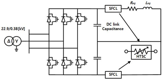
Figure 2.
Concept of SFCL on LVDC system.
- The fault current could be limited quickly by the resistance on the HTSC elements when the quench phenomenon occurs.
- The line losses were reduced than the method of increasing the impedance for limiting fault current.
- The power quality was not degraded compared to the method of changing the capacity of the DC capacitor.
- Since there is no need to upgrade the circuit breaker, the operation cost could be reduced.
3. Simulation Results
Section 3 verified the effectiveness of limiting the fault current when the SFCL was applied using PSCAD/EMTDC. Also, the operational characteristics of the protection relay such as over current relay, selective protection relay were analysed when the fault current was limited by applying the SFCL [5,6,7].
3.1. Fault Analysis in LVDC System
Section 3.1 analysed the short-circuit fault in the LVDC system. In order to solve the complete response of the non-linear circuit, the different stages of the fault are analysed separately. Figure 3 shows the equivalent circuit for the short circuit fault on the LVDC system. The fault analysis on the LVDC system was analysed in detail in three stage from Subsecions Section 3.1.1–Section 3.1.3.
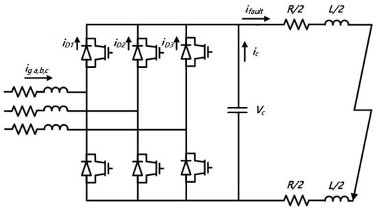
Figure 3.
Equivalent Circuit for Short Circuit Fault in LVDC System.
3.1.1. Stage 1: Capacitor-Discharge Stage (Natural Response)
The first stage on the DC fault analysis is the DC-link capacitor-discharge. When the fault occurs on the LVDC system, the IGBT is quickly opened for self-protection. The capacitor on the DC-link discharges the current to the line. When the fault occurs at time , under the initial conditions of and , Equations (2) and (3) represent the voltage of the DC-link and fault current.
where, and
is represented by Equation (4) when the voltage of the DC link to zero.
where,
3.1.2. Stage 2: Diode Freewheel Stage(Natural Response; After )
The second stage is line inductance discharges the current when the voltage of the DC-link drops to zero. Typically, this stage occurs within a few ms after the fault and the time for the inductance to discharge the current is affected by the capacity of the DC capacitor. The fault current has an initial value . The fault current where each phase-leg freewheel diode current carries a third of the current is represented by Equation (5).
3.1.3. Stage 3: Grid-Side Current Feeding Stage (Forced Response)
3.2. Application of Superconducting Fault Current Limiters (SFCL)
Section 3.2 verified the effect of applying the SFCL through PSCAD/EMTDC. Figure 4 shows the fault current in the LVDC system when the SFCL was applied or not. The peak of the fault current was increased sharply to 4.124 [kA] by the discharge current of the capacitor on the DC-link. The fault current which is rapidly increased than the AC system caused problems for the LVDC system. In order to protect the power conversion system, the LVDC system needed a method for limiting the fault current. This paper proposed the application of the SFCL to take advantage mentioned in Section 2.2. When the SFCL was applied to the LVDC system, the fault current was limited from 4.124 [kA] to 1.494 [kA] due to a resistance of the HTSC elements by quenching phenomenon. As a result, limiting the fault current was confirmed when the SFCL was installed.
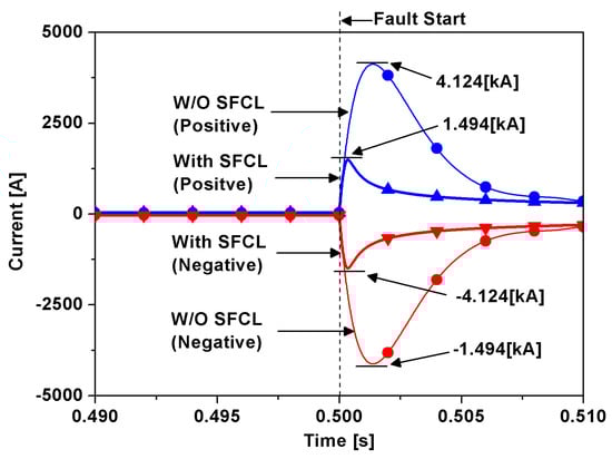
Figure 4.
Fault Current according to apply or not SFCL.
Figure 5 shows the DC voltage in the LVDC system when the SFCL was applied or not. When the SFCL was not applied, the DC voltage dropped to near zero. However, when the SFCL was applied, the DC voltage drop was improved by the resistance of the HTSC. As a result, the improvement of the voltage drop was confirmed when the SFCL was installed.
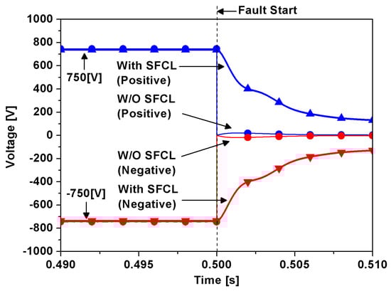
Figure 5.
DC Voltage in LVDC system according to apply or not SFCL.
3.3. Operational Characteristics of Over Current Relay
Section 3.3 describes the operational characteristics of the inverse time relay. The inverse time relay sends the trip signal to the circuit breaker depending on the magnitude of the fault current flowing through the current transformer(CT). The inverse time relay was mainly used in back up protection because the timing of sending the trip signal changes depending on the magnitude of the fault current. The inverse time relay reviewed in this paper were modelled using Equation (8) which represents the extremely inverse (EI) of IEC 60255 standard characteristics [25,26]. In this paper, the time multiplier setting () value of 0.2 was selected for fast fault detection of the LVDC system.
where,
Figure 6, Figure 7 and Figure 8 show the fault current of the positive pole and the trip signal of the protection relay. Figure 6 shows the fault current and trip signal in the over current relay when the SFCL was applied or not. The fault current was limited from 4.124 kA to 1.494 kA by the resistance of the HTSC elements. However, the trip signal was not sent to the circuit breaker because the was reduced by limiting the fault current. To solve the problem of no trip signal, there are two conventional methods. The first method is to change the value of the TMS. The second method is to change the relay setting current () value of . However, these methods which are to change the parameter of the relay are not recommended because it is difficult to take into account changes in the system. In addition, when the HTSC elements are not quenched, the LVDC system is fatally damaged because the relay is not properly working. To solve these problems, the over current relay was set in consideration of the voltage component of the HTSC elements.
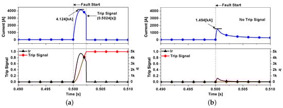
Figure 6.
Fault Current and Trip Signal in Over Current Relay (a) W/O SFCL (b) With SFCL.
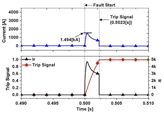
Figure 7.
Fault Current and Trip Signal when using the voltage component of high temperature superconductivity (HTSC) element.
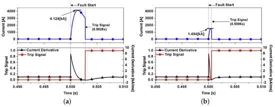
Figure 8.
Fault Current and Trip Signal in Selective Protection Relay (a) W/O SFCL (b) With SFCL.
Equation (9) shows the modified of the over current relay using the voltage component of the HTSC elements. When the fault current was below a critical current, since the HTSC voltage was zero(), the over current relay sent a trip signal to the circuit breaker similar to the case of the without SFCL. On the other hand, when the fault current exceeded a critical current, reduced by the limited fault current could be compensated by the voltage component ().
where,
Figure 7 shows the fault current and trip signal in the over current relay using the voltage component of the SFCL. The fault current was not only limited by the SFCL, but also the malfunction of the over current relay was improved through the use of the voltage component.
3.4. Operational Characteristics of Selective Protection Relay
Section 3.4 describes the operational characteristics of the selective protection relay. The selective protection relay sends a trip signal to the circuit breaker when the derivative() of the fault current flowing through the CT exceeds a certain value. The selective protection relay has been used to main protection because the LVDC system is no phase and a large fault current flows momentarily by the capacitor of the DC-link. Under the normal condition of the LVDC system, the derivative in load current is close to zero. However, when the fault occurs on the LVDC system, the derivative is very high due to the capacitor of the DC-link. The selective protection relay detects the fault by using the derivative in the fault current. Figure 8 shows the fault current and the trip signal of the selective protection relay when the SFCL was applied or not. The fault current was limited from 4.124 [kA] to 1.494 [kA] by the resistance of the HTSC elements. Also, the timing of the trip signal was changed from 0.5028 [s] to 0.5006 [s] due to the change in the derivative.
4. Discussion
Section 3.1 represents the characteristics of the fault current in the LVDC system. In Section 3.2, the effect of limiting fault current on the LVDC system using the SFCL was confirmed. The fault current on the LVDC system was limited through applying SFCL, but this causes a problem in the operational characteristics of the protection relay. In Section 3.3, the trip signal of the over current relay was not sent to the circuit breaker properly due to reducing . Therefore, in this paper, the voltage component of the HTSC was used to improve the relay’s trip signal to the circuit breaker even when the fault current was limited. The reduced by the SFCL was compensated by the voltage component of the HTSC elements. Even if the fault current was limited by applying the SFCL, the over current relay properly detected the fault through the method proposed in this paper. Section 3.4 describes the selective protection relay that are mainly used as main protection relay in the LVDC system. The selective protection relay has quickly detected the fault because the current derivative changed through the application of the SFCL. Therefore, the performance of the fault detection on selective protection relays was improved by applying the SFCL. Table 4 shows the results of the method proposed in this paper.
Table 4.
Simulation Results.
5. Conclusions
The LVDC system has a problem with large fault currents by the capacitor of the DC-link when the fault occurs. To solve these problems of LVDC system, this paper proposed applying an SFCL for limiting fault current in the LVDC system. The operation characteristics of the over current relay which caused malfunction due to limiting fault current was improved by using voltage component proposed in this paper. The selective fault relay operated by derivative has quickly detected the fault by applying the SFCL proposed in this paper. The solution proposed in this paper have the following advantages:
- The fault current on the LVDC system could be limited by applying the SFCL. Therefore, the economics have been improved due to not require the upgrade of the circuit breaker. Also, the LVDC system mitigated the risk of the fault current.
- The DC voltage drop was improved by the resistance of the HTSC elements.
- The line losses were reduced compared to the method of increasing impedance.
- The power quality was not affected compared to the method of changing the capacity of the DC capacitor.
- Unlike other methods, the application of the SFCL for limiting fault current could not affect the system.
- Even if the fault current was limited, the over current relay properly sent the trip signal to the circuit breaker through using the voltage component of the HTSC.
- The operational characteristics of the selective protection relay were improved by applying the SFCL.
Through the advantages mentioned above, the LVDC system could be effectively operated. In the future, it is necessary to research the fault characteristics on the LVDC system according to the system configuration, fault type and location.
Author Contributions
Writing–original draft preparation, H.-J.L.; Methodology, J.-S.K.; Supervision, J.-C.K.; Project administration, S.-Y.Y.; Review and editing, S.-M.C. All authors have read and agreed to the published version of the manuscript.
Funding
This research was supported in part by Korea Electric Power Corporation (Grant number:R18XA04), This work was supported by the Korea Institute of Energy Technology Evaluation and Planning(KETEP) and the Ministry of Trade, Industry & Energy(MOTIE) of the Republic of Korea (No. 2019381010001B).
Conflicts of Interest
The authors declare no conflict of interest.
Nomenclature
| Photovoltaic | |
| Energy Storage System | |
| Insulated Gate Bipolar Transistor | |
| Superconducting Fault Current Limiter | |
| Modular Multi-level Converter | |
| Fault Current Limiter | |
| Superconducting Cable | |
| Power System Computer Aided Design/Electromagnetic Transients including DC | |
| Resistance of HTSC Element | |
| Recovery Starting Time | |
| Coefficients of Experimental Results | |
| Current Transformer | |
| Extremely Inverse | |
| Time Multiplier Setting | |
| High Temperature Superconductivity |
References
- Dragicevic, T.; Juan, C.V.; Josep, M.G.; Davor, S. Advanced LVDC Electrical Power Architectures and Microgrids: A step toward a new generation of power distribution networks. IEEE Electr. Mag. 2015, 2, 54–65. [Google Scholar] [CrossRef]
- Andres, F.M.; Eduardo, M. LVDC microgrid perspective for a high efficiency distribution system. In Proceedings of the IEEE PES Transmission & Distribution Conference and Exposition—Latin America (PES T&D-LA), Medellin, Colombia, 10–13 September2014. [Google Scholar] [CrossRef]
- Abdullah, A.S.E.; Graeme, M.B. An Advanced Protection Scheme for Enabling an LVDC Last Mile Distribution Network. IEEE Trans. Smart Grid 2014, 5, 2602–2609. [Google Scholar] [CrossRef]
- Emhemed, A.; Burt, G. The effectiveness of using IEC61660 for characterising short-circuit currents of future low voltage DC distribution networks. In Proceedings of the 22nd International Conference and Exhibition on Electricity Distribution (CIRED 2013), Stockholm, Sweden, 10–13 June 2013. [Google Scholar] [CrossRef]
- Jin, Y.; John, E.F.; O’Reilly, J. Short-Circuit and Ground Fault Analyses and Location in VSC-Based DC Network Cables. IEEE Trans. Ind. Electr. 2012, 59, 3827–3837. [Google Scholar] [CrossRef]
- Jin, Y.; John, E.F.; O’Reilly, J. Multiterminal DC Wind Farm Collection Grid Internal Fault Analysis and Protection Design. IEEE Trans. Power Deliv. 2010, 25, 2308–2318. [Google Scholar] [CrossRef]
- Kyung-Min, L.; Chul-Won, P. A Study on Fault Current Calculation of 750[V] DC Distribution Grid. Trans. Korean Inst. Electr. Eng. 2018, 67, 1286–1291. [Google Scholar] [CrossRef]
- Salonen, P.; Nuutinen, P.; Peltoniemi, P.; Partanen, J. Protection scheme for an LVDC distribution system. In Proceedings of the CIRED 2009—20th International Conference and Exhibition on Electricity Distribution—Part 1, Prague, Czech Republic, 8–11 June 2009. [Google Scholar]
- Prempraneerach, P.; Angle, M.G.; Kirtley, J.L.; Karniadakis, G.E.; Chryssostomidis, C. Optimization of a z-source DC circuit breaker. In Proceedings of the IEEE Electric Ship Technologies Symposium (ESTS), Paris, France, 22–24 November 2013. [Google Scholar]
- Hye-Won, C.; Hyo-Sang, C. Extension of Cut-off Capacity of DC Circuit Breaker due to Superconducting Coil Application. Trans. Korean Inst. Electr. Eng. 2019, 68, 593–597. [Google Scholar] [CrossRef]
- Hwang, S.-H.; Choi, H.-W.; Jeong, I.-S.; Choi, H.-S. Characteristics of DC Circuit Breaker Applying Transformer-Type Superconducting Fault Current Limiter. IEEE Trans. Appli. Supercond. 2018, 28, 1–5. [Google Scholar] [CrossRef]
- Soo-Hwan, K. A Study on the Fault Analysis in LVDC System Using PSCAD/EMTDC. M.S.; Korea National University of Transportation: Chungju, Korea, 2017. [Google Scholar]
- Abdullah, E.; Fong, K.; Fletcher, S.; Graeme, B. Validation of fast and selective protection scheme for an LVDC distribution network. In Proceedings of the IEEE Manchester PowerTech, Manchester, UK, 18–22 June 2017. [Google Scholar] [CrossRef]
- Bin, L.; Jiawei, H.; Ye, L.; Ruisheng, L. A Novel Solid-State Circuit Breaker With Self-Adapt Fault Current Limiting Capability for LVDC Distribution Network. IEEE Trans. Pow. Electron. 2019, 34, 3516–3529. [Google Scholar] [CrossRef]
- Soo-Hwan, K.; Gyu-Wan, C.; Jong-Fil, M.; Tae-Hoon, K.; Ju-Yong, K. A Study on the Fault Analysis of the LVDC Using PSCAD/EMTDC. Trans. Korean Inst. Electr. Eng. 2016, 65P, 219–223. [Google Scholar]
- Jian-Xun, J.; Xiao-Yuan, C. A Novel Overcurrent Suppression Strategy during Reclosing Process of MMC-HVDC. Appl. Sci. 2019, 9, 1737. [Google Scholar] [CrossRef]
- Jian-Xun, J.; Xiao-Yuan, C. Cooperative Operation of Superconducting Fault-Current-Limiting Cable and SMES System for Grounding Fault Protection in a LVDC Network. IEEE Trans. Ind. Appl. 2015, 51, 5410–5414. [Google Scholar] [CrossRef]
- Khan, U.A.; Shin, W.J.; Seong, J.K.; Oh, S.H.; Lee, S.H.; Lee, B.W. Feasibility analysis of the application and positioning of DC HTS FCL in a DC microgrid through modeling and simulation using Simulink and SimPowerSystem. Phys. C Supercond. Appl. 2011, 471, 1322–1326. [Google Scholar] [CrossRef]
- Aref, M.; Abdelmeneam, A.; Oboskalov, V.; Mahnitko, A.; Gavrilov, A. Transient Analysis of AC and DC Microgrid with Effective of SFCL. In Proceedings of the IEEE 59th International Scientific Conference on Power and Electrical Engineering of Riga Technical University (RTUCON), Riga, Latvia, 12–14 November 2018. [Google Scholar] [CrossRef]
- Waqas, J.; Dong, C.; Ema, M.F.; Yan, X. System Configuration, Fault Detection, Location, Isolation and Restoration: A Review on LVDC Microgrid Protections. Energies 2019, 12, 1001. [Google Scholar] [CrossRef]
- Jae-Sang, H.; Khan, U.A.; Woo-Ju, S.; Jae-Kyu, S.; Jong-Geon, L.; Yong-Han, K.; Bang-Wook, L. Validity Analysis on the Positioning of Superconducting Fault Current Limiter in Neighboring AC and DC Microgrid. IEEE Trans. Appl. Supercond. 2013, 23. [Google Scholar] [CrossRef]
- Xue, S.; Gao, F.; Sun, W.; Li, B. Protection principle for a DC distribution system with a resistive superconductive fault current limiter. Energies 2015, 8, 4839. [Google Scholar] [CrossRef]
- Zhang, L.; Nengling, T.; Huang, W.; Jian, L.; Yanhong, W. A review on protection of DC microgrids. J. Mod. Pow. Syst. Clean Energy 2018, 6, 1113–1127. [Google Scholar] [CrossRef]
- Kaipei, L.; Qing, H.; Liang, Q.; Shu, Z.; Xiaobing, L.; Yuye, L.; Hua, D. Enhanced Fault Current-Limiting Circuit Design for a DC Fault in a Modular Multilevel Converter-Based High-Voltage Direct Current System. Appl. Sci. 2019, 9, 1661. [Google Scholar] [CrossRef]
- Abdulfetah, S.; Baysal, M.; Wadi, M.; Mehmet, R.T. Protection Coordination Practices for Industrial Ring Distribution Network Case Study of Organized Industrial Zone (GEBZE, Turkey). In Proceedings of the 7th International Conference on Renewable Energy Research and Applications (ICRERA), Paris, France, 14–17 October 2018. [Google Scholar] [CrossRef]
- Grid, A. Network Protection and Automation Guide-Protective Relays; Alstom Grid: Saint-Ouen-sur-Seine, France, 2011. [Google Scholar]
- Jong-Il, S. Development of Fault Detection Algorithm Using Current Derivative Characteristic in Low Voltage Direct Current Distribution System. M.S; Sungkyunkwan University: Gyeonggi-do, Korea, 2017. [Google Scholar]
- Jong-Il, S.; Chul-Ho, N.; Gi-Hyeon, G.; Yun-Sik, O.; Joon, H.; Chul-Hwan, K. A Study on Applicability of Protection Algorithms of AC Distribution System to DC Distribution System. J. Korean Inst. Illum. Electr. Install. Eng. 2016. [Google Scholar] [CrossRef]
- Dong, W.; Abdullah, E.; Graeme, B. A novel protection scheme for an LVDC distribution network with reduced fault levels. In Proceedings of the 2017 IEEE Second International Conference on DC Microgrids (ICDCM), Nuremberg, Germany, 27–29 June 2017. [Google Scholar] [CrossRef]
- Ok-Bae, H.; Sang-Do, C.; Hye-Rim, K.; Hyo-Sang, C.; Si-Dol, H. Shunt-assisted simultaneous quenches in series-connected resistive SFCL components. IEEE Trans. Appl. Supercond. 2003, 13, 2060–2063. [Google Scholar] [CrossRef]
- Dong, K.P.; Seong, E.Y.; Yong, S.Y.; Min, C.A.; Ho, M.K.; Yeong, S.K.; Jung-Wook, P.; Tae, K.K. Analysis of the Operational Characteristics of a Resistive SFCL by Using the YBCO Coated Conductor. IEEE Transactions Trans. Appl. Supercond. 2007, 17, 1851–1854. [Google Scholar] [CrossRef]
- Jin-Seok, K.; Sung-Hun, L.; Jae-Chul, K. Study on Application Method of Superconducting Fault Current Limiter for Protection Coordination of Protective Devices in a Power Distribution System. IEEE Trans. Appl. Supercond. 2012, 22. [Google Scholar] [CrossRef]
- Seung-Taek, L.; Sung-Hun, L. Analysis on Operational Improvement of OCR Using Voltage Component in a Power Distribution System for Application of SFCL. J. Electr. Eng. Technol. 2019, 14, 1027–1033. [Google Scholar] [CrossRef]
- Hyeong-Jin, L.; Sung-Hun, L.; Jae-Chul, K. Application of a Superconducting Fault Current Limiter to Enhance the Low-Voltage Ride-Through Capability of Wind Turbine Generators. Energies 2019, 12, 1478. [Google Scholar]
© 2020 by the authors. Licensee MDPI, Basel, Switzerland. This article is an open access article distributed under the terms and conditions of the Creative Commons Attribution (CC BY) license (http://creativecommons.org/licenses/by/4.0/).