Parallel Loop Control for Torque and Angular Velocity of BLDC Motors with DTC Commutation


Abstract
1. Introduction
2. Mathematical Model of a BLDC Motor and Driver
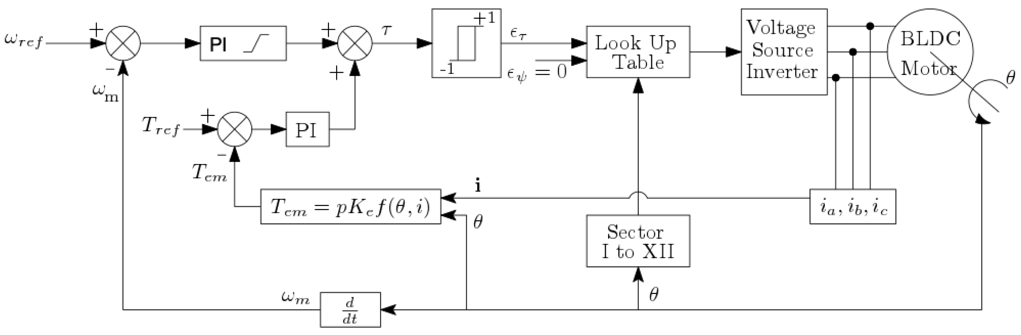
3. Control Loop
4. Direct Torque Control (DTC)
- Define voltage vectors and work sectors in the plane.
- Study the effect of the voltage vectors on the magnetic flux of the stator on each sector of the plane, and define a look-up table for the angular position of the rotor.
- Using a measurement of the actual angular position of the rotor and the control error as entry readings of the look-up table, we find the voltage vector, which is to be applied to the phases of the motor.
5. Simulation
5.1. Simulation Block Parameters
5.2. Simulated Comparison Test
- Rise time/Fall time ()
- Settling time ()
- Mean value ()
- Ripple value ()
5.3. Simulation Results
5.4. Discussion
- At the beginning, when the rotor is gathering up speed, from 0–2500 rpm, an overshoot is observed on the torque response for both controllers. For the cascaded PI controller, this overshoot goes up to a maximum of 15 N·m. In the case of the parallel PI controller, the overshoot goes over 20 N·m. Although this may be seen as a disadvantage, it can be observed that the duration of the overshoot in the parallel PI controller is shorter than in the cascaded PI controller.
- Moving to operation point B, when speed is now reduced to 1500 rpm, an overshoot on the torque is now observed in the opposite direction. In this case, the magnitude of the overshoot is smaller for the parallel PI controller, reaching N·m. For the cascaded PI controller, the overshoot reaches close to N·m but shows a shorter duration than that of the parallel PI controller.
- The time span of the rise time in the speed plot corresponds to the duration of the torque overshoot. Therefore, on the one hand, it can be concluded that under simultaneous speed-torque control, torque must be increased transiently in order to increase the speed. On the other hand, torque must be reduced in order to reduce speed. This interrelation between torque and speed can be explained by studying Equation (11). Here, the input to control speed is precisely . Whence, reducing the angular speed requires a negative torque.
- From visual inspection, it becomes evident that the controller is insensitive to changes in the load torque. This is different from the cascaded controller when speed must remain constant, while a change on the torque set-point must be performed. This is illustrated in points C and D. In clear contrast, the parallel loop allows that both speed and torque be regulated with a small or no error at all.
- It can be observed that, in the case of the cascaded PI controller, there is a steady state error, which is proportional to the magnitude of the reference torque . This is not the case for the parallel PI controller.
- Taking into account the response time, insensitivity to torque changes, steady state error, and the level of torque ripple, it can be concluded that the proposed parallel controller offers an improved performance over the cascaded controller.
6. Conclusions
Author Contributions
Funding
Conflicts of Interest
References
- Belov, M.P.; Dang Khoa, T.; Truong, D.D. BLDC of Robotic Manipulators with Neural Torque Compensator based Optimal Robust Control. In Proceedings of the 2019 IEEE Conference of Russian Young Researchers in Electrical and Electronic Engineering (EIConRus), Saint Petersburg and Moscow, Russia, 28–31 January 2019; pp. 437–441. [Google Scholar]
- Nagaraju, A. Modeling of Direct Torque Control ( DTC ) of BLDC Motor Drive. Int. J. Sci. Technol. Eng. 2017, 3, 413–419. [Google Scholar]
- Liu, Y.; Zhu, Z.Q.; Howe, D. Commutation-torque-ripple minimization in direct-torque-controlled PM brushless DC drives. IEEE Trans. Ind. Appl. 2007, 43, 1012–1021. [Google Scholar] [CrossRef]
- Liu, Y.L.Y.; Zhu, Z.Q.; Howe, D. Direct torque control of brushless DC drives with reduced torque ripple. IEEE Trans. Ind. Appl. 2005, 41, 599–608. [Google Scholar] [CrossRef]
- Lad, C.K.; Chudamani, R. A simple overlap angle control strategy for reducing commutation torque ripple in a brushless DC motor drive. Eng. Sci. Technol. Int. J. 2017, 20, 1406–1419. [Google Scholar] [CrossRef]
- Korkmaz, F.; Topaloğlu, I.; Mamur, H. Modified Direct Torque Control for Bldc Motor Drives. Int. J. Control Theory Comput. Model. (IJCTCM) 2016, 6, 1–9. [Google Scholar] [CrossRef]
- Korkmaz, F. A New Approach to DTC Method For BLDC Motor Adjustable Speed Drives. Comput. Sci. Inf. Technol. 2016, 6, 37–44. [Google Scholar]
- Hadeed, H.; Gottscheber, A. Six Step Control vs Direct Torque Control comparative evaluation for BLDC drive. Int. J. Recent Innov. Trends Comput. Commun. 2017, 5, 422–427. [Google Scholar]
- Garcia, X.d.T.; Zigmund, B.; Terlizzi, A.A.; Pavlanin, R.; Salvatore, L. Comparison between FOC and DTC Strategies for Permanent Magnet Synchronous Motors. Adv. Electr. Electron. Eng. 2006, 5, 76–81. [Google Scholar]
- Gao, J.; Hu, Y. Direct self-control for BLDC motor drives based on three-dimensional coordinate system. IEEE Trans. Ind. Electron. 2010, 57, 2836–2844. [Google Scholar]
- Li, W.; Wu, A.; Wang, Y.; Dong, N. Direct torque control for BLDCM based on optimized sliding mode observer. In Proceedings of the 2016 12th World Congress on Intelligent Control and Automation (WCICA), Guilin, China, 12–15 June 2016; pp. 2907–2912. [Google Scholar]
- Yang, J.; Hu, Y.; Huang, W.; Chu, J.; Gao, J. Direct torque control of Brushless DC motor without flux linkage observation. In Proceedings of the 2009 IEEE 6th International Power Electronics and Motion Control Conference, Wuhan, China, 17–20 May 2009; pp. 1934–1937. [Google Scholar]
- Haipeng, P.; Minming, G.; Junjie, G. A Kind of Simplified Structure Direct Torque Control Method for Brushless DC Motor. In Proceedings of the 2013 Third International Conference on Instrumentation, Measurement, Computer, Communication and Control, Shenyang, China, 21–23 September 2013; pp. 1480–1483. [Google Scholar]
- Geraee, S.; Shafiei, M.; Sahami, A.R.; Alavi, S. Position sensorless and adaptive speed design for controlling brushless DC motor drives. In Proceedings of the 2017 North American Power Symposium (NAPS), Morgantown, WV, USA, 17–19 September 2017; pp. 1–6. [Google Scholar]
- Mars, R.; Bouzidi, B.; Badsi, B.E.; Yangui, A. DTC of three-level inverter fed brushless DC motor drives with torque ripple reduction. In Proceedings of the 2018 Thirteenth International Conference on Ecological Vehicles and Renewable Energies (EVER), Monte-Carlo, Monaco, 10–12 April 2018; pp. 1–10. [Google Scholar]
- Sandeep, J.; Nair, D.S.; George, S.; Ashok, S.; Jagadan, G.; Ramchand, R. Performance Comparison of Direct Torque Controlled Permanent Magnet Machines. In Proceedings of the IECON 2018—44th Annual Conference of the IEEE Industrial Electronics Society, Washington, DC, USA, 21–23 October 2018; pp. 631–636. [Google Scholar]
- Uyar, O.; Cunkas, M. Torque and Speed Control of BLDC Motor for Pedelec. In Proceedings of the 5th International Conference on Innovation in Science and Technology, Barcelona, Spain, 7–9 December 2018; pp. 64–73. [Google Scholar]
- Sharma, T.R.; Pal, Y. Direct Torque Control of BLDC Drives With Reduced Torque Pulsations. In Proceedings of the 2019 3rd International conference on Electronics, Communication and Aerospace Technology (ICECA), Coimbatore, India, 12–14 June 2019; pp. 1242–1247. [Google Scholar]
- Kommula, B.N.; Kota, V.R. Direct instantaneous torque control of Brushless DC motor using firefly Algorithm based fractional order PID controller. J. King Saud Univ. - Eng. Sci. 2018, 32, 133–140. [Google Scholar] [CrossRef]
- Yuan, T.; Wang, D. Performance Improvement for PMSM DTC System through Composite Active Vectors Modulation. Electronics 2018, 7, 263. [Google Scholar] [CrossRef]
- Park, J.B.; Wang, X. Sensorless Direct Torque Control of Surface-Mounted Permanent Magnet Synchronous Motors with Nonlinear Kalman Filtering. Energies 2018, 11, 969. [Google Scholar] [CrossRef]
- Wang, D.; Yuan, T.; Wang, X.; Wang, X.; Li, W. A Composite Vectors Modulation Strategy for PMSM DTC Systems. Energies 2018, 11, 2729. [Google Scholar] [CrossRef]
- Agrawal, L.K.; Chauhan, B.K.; Banerjee, G.K. A Composite Vectors Modulation Strategy for PMSM DTC Systems. Int. J. Pure Appl. Math. 2018, 116, 3955–3959. [Google Scholar]
- Vas, P. Sensorless Vector and Direct Torque Control; Monographs in Electrical and Electronic Engineering; Oxford University Press: New York, NY, USA, 1998; Volume 1, p. 768. [Google Scholar]
- Toufouti, R.; Meziane, S.; Benalla, H. Direct Torque Control for Induction Motor Using Fuzzy Logic. ACSE J. 2006, 6, 19–26. [Google Scholar]
- Ozturk, S.B.; Toliyat, H.A. Direct torque control of brushless dc motor with non-sinusoidal back-EMF. In Proceedings of the 2007 IEEE International Electric Machines Drives Conference, Antalya, Turkey, 3–5 May 2007; pp. 165–171. [Google Scholar]
- Xia, C.L. Permanent Magnet Brushless DC Motor Drives and Controls; John Wiley & Sons Singapore Pte. Ltd.: Singapore, 2012. [Google Scholar]
- Krause, P.C.; Wasynczuk, O.; Sudhoff, S.D.; Pekarek, S. Analysis of Electric Machinery and Drives Systems, 2nd ed.; Wiley-IEEE Press: Piscataway, NJ, USA, 2002. [Google Scholar]
- Astrom, K.J.; Rundqwist, L. Integrator Windup and How to Avoid It. In Proceedings of the 1989 American Control Conference, Pittsburgh, PA, USA, 21–23 June 1989; pp. 1693–1698. [Google Scholar]
- Akshay, R.S.R.; Chaudhari, M.A. Direct torque control of PM BLDC motor using fuzzy controllers. In Proceedings of the 2017 International Conference on Innovations in Information, Embedded and Communication Systems (ICIIECS), Coimbatore, India, 17–18 March 2017; pp. 1–6. [Google Scholar]


| 1 | |||||||||||||
| Parameter | Description | Value |
|---|---|---|
| Drain to source on resistance | 1 | |
| Flyback (or body) diode resistance | 10 m | |
| Flyback diode inductance | 0 mH | |
| Diode on voltage | V |
| Parameter | Description | Value |
|---|---|---|
| Power source voltaje | 300 V | |
| p | Number of pole pairs | 4 |
| Number of phases | 3 | |
| Nominal speed without load | 5000 rpm | |
| Nominal torque of the motor | 6 N·m | |
| Wiring resistance | ||
| Wiring self-inductance | 1 mH | |
| back-EMF constant | V/(rad/s) | |
| J | Rotor inertia coefficient | Kg/m |
| Viscous friction coefficient | N/(rad/s) |
| Point | t | ||
|---|---|---|---|
| (s) | (rpm) | (N·m) | |
| A | 0 | 2500 | 6 |
| B | 1500 | 6 | |
| C | 1500 | ||
| D | 1500 | 6 |
| Operational Range | |||||||||
|---|---|---|---|---|---|---|---|---|---|
| RT | FT | Mean | Ripple | RT | FT | Mean | Ripple | ||
| (rpm) | (N·m) | (ms) | (ms) | (rpm) | (rpm) | (s) | (s) | (N·m) | (N·m) |
| 0–2500 | 6 | - | 1 | ||||||
| 2500–1500 | 6 | - | |||||||
| 1500 | - | - | |||||||
| 1500 | - | - | |||||||
| Operational Range | |||||||||
|---|---|---|---|---|---|---|---|---|---|
| RT | FT | Mean | Ripple | RT | FT | Mean | Ripple | ||
| (rpm) | (N·m) | (ms) | (ms) | (rpm) | (rpm) | (s) | (s) | (N·m) | (N·m) |
| 0–2500 | 6 | - | 1 | ||||||
| 2500–1500 | 6 | - | |||||||
| 1500 | 6–1.2 | - | |||||||
| 1500 | 1.2–6 | - | |||||||
© 2020 by the authors. Licensee MDPI, Basel, Switzerland. This article is an open access article distributed under the terms and conditions of the Creative Commons Attribution (CC BY) license (http://creativecommons.org/licenses/by/4.0/).
Share and Cite
Coballes-Pantoja, J.; Gómez-Fuentes, R.; Noriega, J.R.; García-Delgado, L.A. Parallel Loop Control for Torque and Angular Velocity of BLDC Motors with DTC Commutation. Electronics 2020, 9, 279. https://doi.org/10.3390/electronics9020279
Coballes-Pantoja J, Gómez-Fuentes R, Noriega JR, García-Delgado LA. Parallel Loop Control for Torque and Angular Velocity of BLDC Motors with DTC Commutation. Electronics. 2020; 9(2):279. https://doi.org/10.3390/electronics9020279
Chicago/Turabian StyleCoballes-Pantoja, J., R. Gómez-Fuentes, J. R. Noriega, and L. A. García-Delgado. 2020. "Parallel Loop Control for Torque and Angular Velocity of BLDC Motors with DTC Commutation" Electronics 9, no. 2: 279. https://doi.org/10.3390/electronics9020279
APA StyleCoballes-Pantoja, J., Gómez-Fuentes, R., Noriega, J. R., & García-Delgado, L. A. (2020). Parallel Loop Control for Torque and Angular Velocity of BLDC Motors with DTC Commutation. Electronics, 9(2), 279. https://doi.org/10.3390/electronics9020279