Article

A New CPW-Fed Diversity Antenna for MIMO 5G Smartphones

by
Naser Ojaroudi Parchin
1,*,
Haleh Jahanbakhsh Basherlou
2,
Yasir I. A. Al-Yasir
1,
Ahmed M. Abdulkhaleq
1,3,
Mohammad Patwary
4 and
Raed A. Abd-Alhameed
1
1
Engineering and Informatics, University of Bradford, Bradford BD7 1DP, UK
2
Bradford College, Bradford BD7 1AY, UK
3
SARAS Technology Limited, Leeds LS12 4NQ, UK
4
School of Computing and Digital Technology, Birmingham City University, Birmingham B5 5JU, UK
*
Author to whom correspondence should be addressed.
Electronics 2020, 9(2), 261; https://doi.org/10.3390/electronics9020261
Submission received: 31 December 2019 / Revised: 27 January 2020 / Accepted: 28 January 2020 / Published: 4 February 2020
(This article belongs to the Special Issue Recent Technical Developments in Energy-Efficient 5G Mobile Cells)

Abstract

:
In this study, a new coplanar waveguide (CPW)-fed diversity antenna design is introduced for multiple-input–multiple-output (MIMO) smartphone applications. The diversity antenna is composed of a double-fed CPW-fed antenna with a pair of modified T-ring radiators. The antenna is designed to cover the frequency spectrum of commercial sub-6 GHz 5G communication (3.4–3.8 and 3.8–4.2 GHz). It also provides high isolation, better than −16 dB, without an additional decoupling structure. It offers good potential to be deployed in future smartphones. Therefore, the characteristics and performance of an 8-port 5G smartphone antenna were investigated using four pairs of the proposed diversity antennas. Due to the compact size and also the placement of the elements, the presented CPW-fed smartphone antenna array design occupies a very small part of the smartphone board. Its operation band spans from 3.4 to 4.4 GHz. The simulated results agree well with measured results, and the performance of the smartphone antenna design in the presence of a user is given in this paper as well. The proposed MIMO design provides not only sufficient radiation coverage supporting different sides of the mainboard but also polarization diversity.

1. Introduction

With the creation of standards for and the development of fifth-generation (5G) mobile communication, more and more research has been conducted into related technologies with the hope of achieving a higher transmission rate, lower cost and higher gain [1,2,3]. Multiple-input–multiple-output (MIMO) technology is a key to realizing a higher transmission rate [4]. By using MIMO technology, multiple independent channels can be achieved on the original spectrum by the diversity method, and multipath fading can be reduced so as to improve the data transmission rate. A MIMO antenna is a significant facility to improve the channel capacity of a MIMO system [5,6,7,8]. MIMO systems of 2 × 2 are successfully employed for 4G mobile networks, and a large number of antenna elements are expected to be applied for 5G communications [9,10].
Several kinds of 5G MIMO smartphone antennas have been put forward recently [11,12,13,14,15,16,17,18,19,20,21,22,23,24,25] (see Table 2 for details). However, these MIMO antenna designs either suffer from a narrow frequency bandwidth or occupy a huge space on a smartphone mainboard. Furthermore, some of the reported designs use uniplanar radiators, which are difficult to fabricate and integrate with the 5G smartphone circuit. In the designs of many MIMO antennas, it is common to avoid placing elements in parallel and to choose instead to place them vertically, which can avoid strong mutual couplings caused by the same polarization mode. In this paper, however, the antenna elements are both perpendicular and parallel to each other to exhibit the diversity function. In addition, the T-shaped strip of the antenna configuration can act as a decoupling structure. Due to compact size and also placement of the antenna, the proposed MIMO design occupies a very small part of the smartphone printed circuit board (PCB). Therefore, the antenna achieves not only low mutual couplings but also small clearance.
The antenna elements of the MIMO design are fed using the coplanar waveguide feeding mechanism in order to operate at sub-6 GHz 5G communication (3.4–3.8 and 3.8–4.2 GHz) [26]. Compared with probe-fed and microstrip-fed antennas, coplanar waveguide (CPW)-fed antennas can easily achieve the wideband impedance matching [27,28]. Therefore, CPW-fed antennas are widely used and becoming increasingly popular in wireless applications owing to their attractive features such as compact size, conformal status, their light weight and ease of fabrication and integration with wireless communication systems [29,30]. The paper is organized as follows: The design and characteristics of the diversity antenna element are represented in Section 2. Section 3 discusses the MIMO performance and radiation characteristics of the proposed 5G smartphone antenna array. Section 4 investigates the radiation behavior of the designed smartphone antenna array in the vicinity of the user. Section 5 gives the conclusion of this paper.

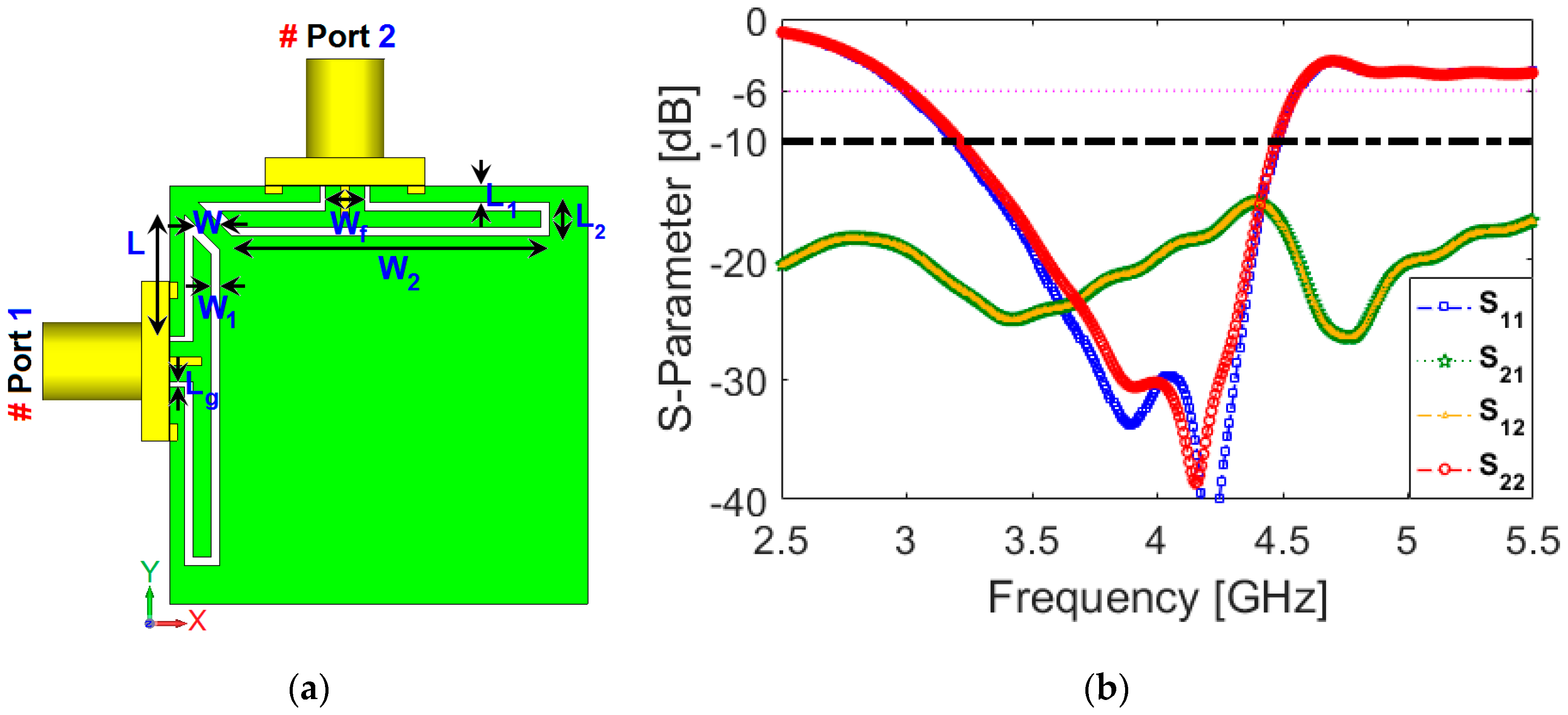
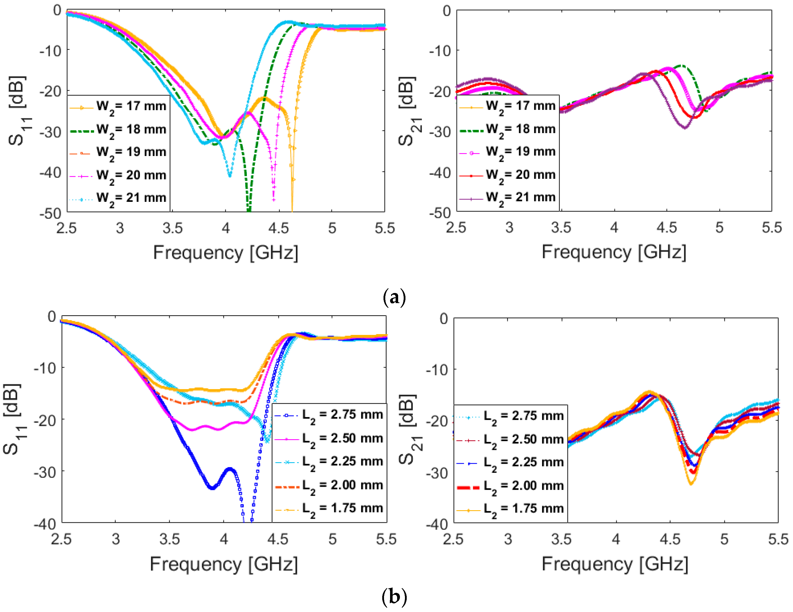
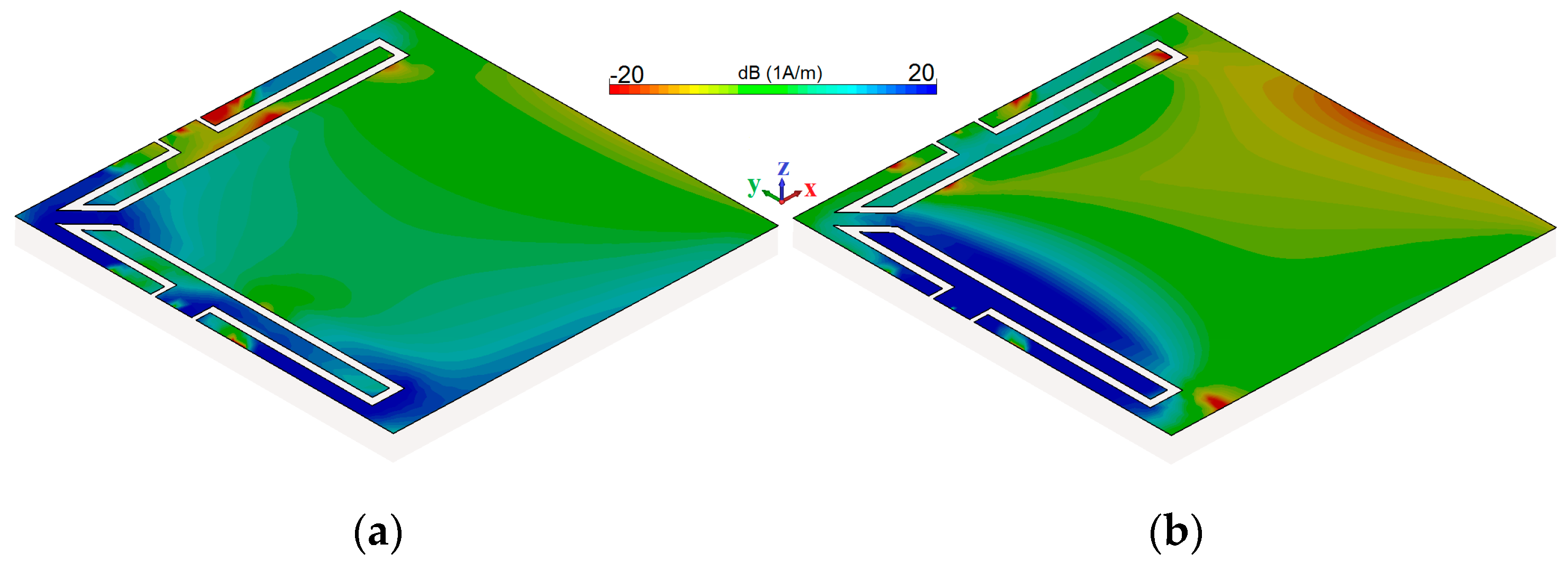
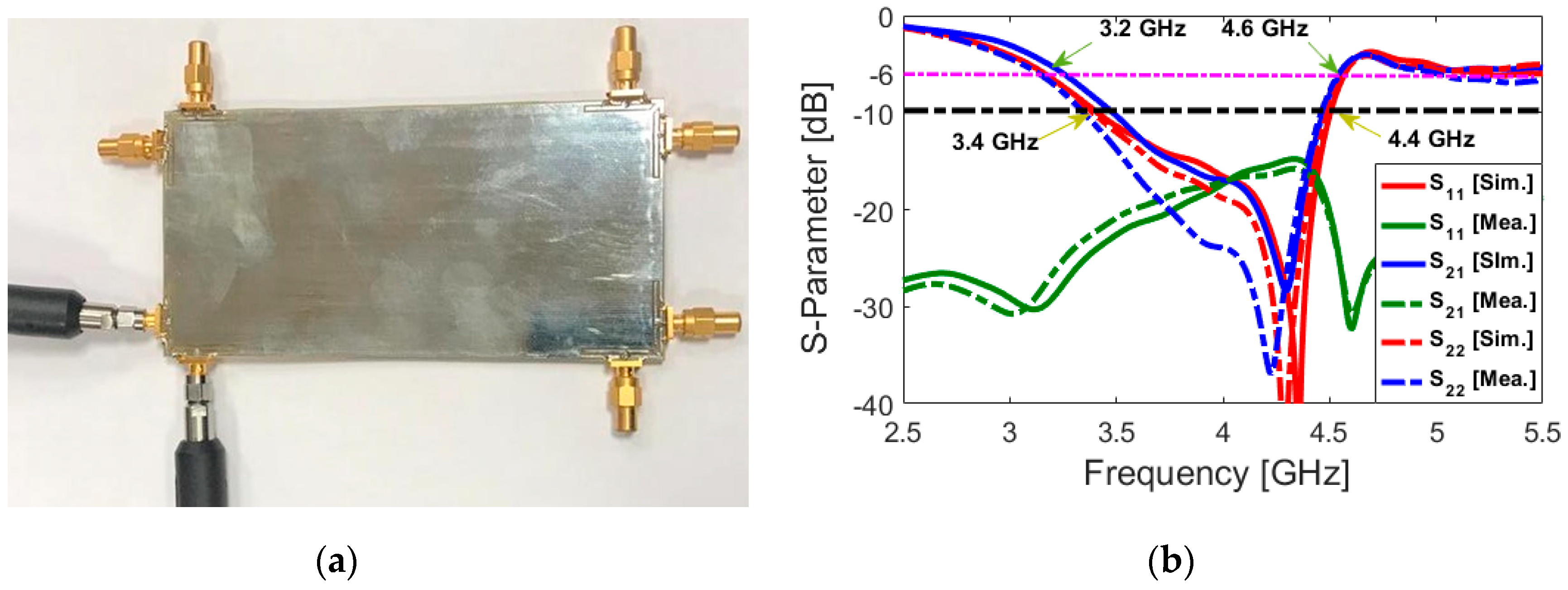
2. The Proposed CPW-Fed Diversity Antenna

The characteristics of the single-element diversity antenna are discussed in this section. Its structure is shown in Figure 1a. It is shown that the schematic of the diversity antenna contains a pair of modified CPW-fed T-ring resonators. As seen, the proposed antenna is designed on one side of the FR4 dielectric. In addition, as seen, SMA (SubMiniature version A) connectors are also embedded in the simulations. Figure 1b depicts the S-parameters of the proposed CPW-fed diversity antenna. As illustrated, the designed antenna provides a wide operation band of 3.2–4.4 GHz, supporting both target bands, including 3.4–3.8 and 3.8–4.2 GHz. It should be noted that the arrow-shaped strip of the design, placed between the elements, can act as a decoupling structure and increase the isolation between the antenna ports. Therefore, the mutual coupling (S12/S21) is successfully reduced. As can be observed, greater than −15 dB (with −20 dB value at the center frequency (4 GHz)) has been achieved for the designed diversity antenna. The characteristics of the antenna are investigated using computer simulation technology (CST) software [31]. The detailed dimensions of the designed CPW-fed diversity antenna are shown in Table 1.
The frequency behavior of the proposed diversity antenna is very flexible. Figure 2 discusses the impedance matching and frequency tuning of the antenna. Figure 2a illustrates the S11 and S21 characteristics versus different values of W2. As seen, when its value increases from 17 to 21 mm, the lower and upper operation frequencies of the antenna increase from 3 to 3.4 and 4.5 to 4.8 GHz, respectively. In addition, as can be observed, the S21 function of the diversity antenna tunes by changing the value of W2. Figure 2b investigates the impedance matching function of the antenna for various values of L2: when its size changes from 2.75 to 1.75 mm, the matching characteristic of the diversity antenna varies from −14 to less than −30 dB. However, unlike Figure 2a, the S21 is almost constant with an insignificant variation.
In order to have a better illumination about the working mechanism of the CPW-Fed, its simulated current distributions at 3.8 and 4.2 GHz are shown in Figure 3. As shown at 3.8 GHz, the current is mainly distributed near the arrow strip and outer boundary of the modified T-ring resonator, which verifies the role of the strip in creating a new resonance at 3.8 GHz. At 4.2 GHz, the currents are mainly concentrated inside of the modified T-ring slot [31,32]. The radiation patterns of the diversity antenna for each exciting port at 4 GHz (center frequency of the antenna operation band) are plotted in Figure 4. It is shown that well-defined polarization and pattern diversity is obtained for the antenna. The radiation patterns of the antenna are symmetrical, covering the top/bottom sides of the substrate and providing similar radiation behavior with a gain value of 3.6 dB. The fundamental radiation characteristics of the diversity antenna are also given in Figure 5 within the range of 3.4–4.4 GHz (with 0.1 GHz/step). As illustrated in Figure 5, the antenna exhibits high efficiencies over its 1 GHz impedance bandwidth. In addition, the antenna offers sufficient gain and directivity in the range of 3.4–4.4 GHz.
A prototype of the design was fabricated and its S parameters were tested. In order to verify the simulated S-parameter results mentioned above, the single-element diversity antenna was fabricated and measured. A vector network analyzer was used to measure the antenna in our research. The fabricated dual-port antenna and the measured results of S-parameters are given in Figure 6a,b. As illustrated in Figure 6b, the measured results of the diversity antenna based on FR-4 are very close to the simulated results’ values within 2.5–5.5 GHz; it provides quite a good impedance bandwidth (S11 < −10 dB within 3.2–4.4 GHz), and its mutual coupling (S21) is less than −15 dB.
The total active reflection coefficient (TARC), envelope correlation coefficient (ECC) and diversity gain (DG) characteristics are important parameters to be considered in diversity/MIMO antennas and can be calculated using the below formulas [33,34,35].
T A R C = ( S 11 + S 12 ) 2 + ( S 21 + S 22 ) 2 2
E C C = | S 11 * S 21 + S 12 * S 22 | 2 ( 1 | S 11 | 2 | S 12 | 2 ) ( 1 | S 21 | 2 | S 22 | 2 ) *
D G = 10 1 ( E C C ) 2
Figure 7 represents the calculated TARC, ECC and DG characteristics for the proposed dual-port diversity antenna. As shown in Figure 7a,b, the TARC and ECC results of this diversity antenna are very low within the band, which means the antenna is competent for diversity reception/transmission in the MIMO channels [33]. In addition, as can be observed from Figure 7c, the DG function of the design is greater than 9.97 dB over the entire band.

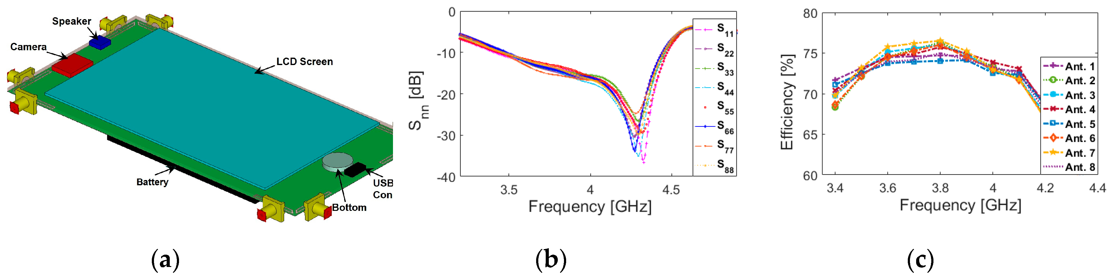
3. Mobile-Phone Antenna Design

Four pairs of the modified CPW-fed diversity antenna mentioned above were placed in different corners of the smartphone board to form an eight-port MIMO antenna with a standard size of 150 × 75 × 1.6 mm3. Its structure is shown in Figure 8. As can be observed, due to the compact size and also the placement of the CPW-fed ring antenna, the proposed MIMO design occupies a very small part of the board.
Figure 9 shows the S-parameters of the CPW-fed MIMO smartphone antenna. It can be observed from Figure 9a that all antenna elements exhibit good return loss results covering 3.4–4.4 GHz. It should also be noted that due to the effect of the MIMO configuration and also the big ground plane of the smartphone board, the lower operation frequency shifted from 3.2 to 3.4 GHz. However, it still covers the target 5G bands including 3.4–3.8 and 3.8–4.2 GHz. The isolations between ports are shown in Figure 9b. The maximum mutual couplings of the diversity antenna arrays are usually between the closely spaced diversity elements such as Ant. 1 and Ant. 2. Due, however, to similar performances and placements of the antenna pairs in the configuration of the proposed smartphone antenna, it is not necessary to show all S-parameters. As seen from Figure 9b, the isolation levels of the antenna ports are less than 16 dB within 3.4–4.4 GHz. This is mainly due to the strong mutual couplings between the adjacent ports. Figure 10 plots the radiation patterns at the middle frequency (4 GHz) of the first CPW-fed diversity antenna (with ports 1 and 2) mounted onto the smartphone PCB. As seen, the radiation patterns are symmetrical covering the top/bottom sides of the substrate and providing similar radiation behavior with gain vale of 4 dBi.
The 3D patterns of antenna radiations at 4 GHz for each feeding port have been illustrated in Figure 11. It can be observed that the CPW-fed resonators not only can cover different sides of the mobile-phone board but also support different polarizations, which is a unique function of the MIMO design [36,37]. In addition, due to the different placements of antenna elements (Ant. 1 and Ant. 2, for example), gain values of 4.6/5.15 dB are achieved for the resonators. The efficiencies (radiation and total) of the CPW-fed ring slot resonators are also given in Figure 12. It is evident that high efficiencies with slight variations are achieved within the range of 3.4–4.4 GHz: more than 80% radiation and 70% total efficiencies were observed for the CPW-fed elements of the proposed MIMO design.
A prototype of the 5G smartphone antenna design was fabricated and fed for measurements, as illustrated in Figure 13. In order to verify the simulated results of the smartphone antenna—mentioned above—the S-parameter and radiation patterns were measured. Due, however, to similar placements and also the performances of the CPW-fed antenna pairs, the properties of the smartphone antenna design for port 1 and 2 were measured and compared in the following way. A vector network analyzer and antenna chamber room were used in the measurement process in our research. The feeding mechanism of the design is shown in Figure 14a. During the measurements, in order to avoid unwanted mutual effects, 50-Ω RF loads are installed for the elements not under test. The measured and simulated results of the S-parameters are compared in Figure 14b. As seen, the measured results are in good agreement with the simulated results to cover the required operation band: a quite good impedance bandwidth (S11 < −10 dB within 3.4–4.4 GHz) and mutual coupling (S21< −15 dB) are obtained for the smartphone antenna design.
Measured and simulated radiation patterns are shown in Figure 15. When measuring radiation patterns, we keep one port excited and another one loaded with a 50-Ω load. In the measurement of radiation patterns, the smartphone MIMO antenna is used as the receiver, and a horn antenna is used as the transmitter. As can be observed from Figure 15 a,b, the sample smartphone antenna prototype offers good quasi-omnidirectional radiation patterns with an acceptable agreement between simulations and measurements [38,39,40].
Table 2 provides a comparison between the presented smartphone array antenna and another reported smartphone array [11,12,13,14,15,16,17,18,19,20,21,22,23,24,25]. As can be observed, compared with the recently proposed 5G MIMO smartphone antennas with planar and uniplanar structures, our antenna performs better in terms of impedance match and bandwidth, and its clearance size remains at a satisfactory level, as shown in Table 2. The proposed design achieves not only approximately 1 GHz impedance bandwidth but also sufficient mutual couplings, better than −15 dB. Unlike the reported 5G antenna design, our antenna is implemented in one-side of the smartphone mainboard using CPW-fed technology, which makes it easy to fabricate and integrate with the circuit. It is apparent that all the listed antennas have double-sides or uniplanar configuration. In addition, due to the small clearance of the proposed smartphone antenna, its fundamental radiation properties in data and talk modes are not reduced significantly, as discussed in the following section.

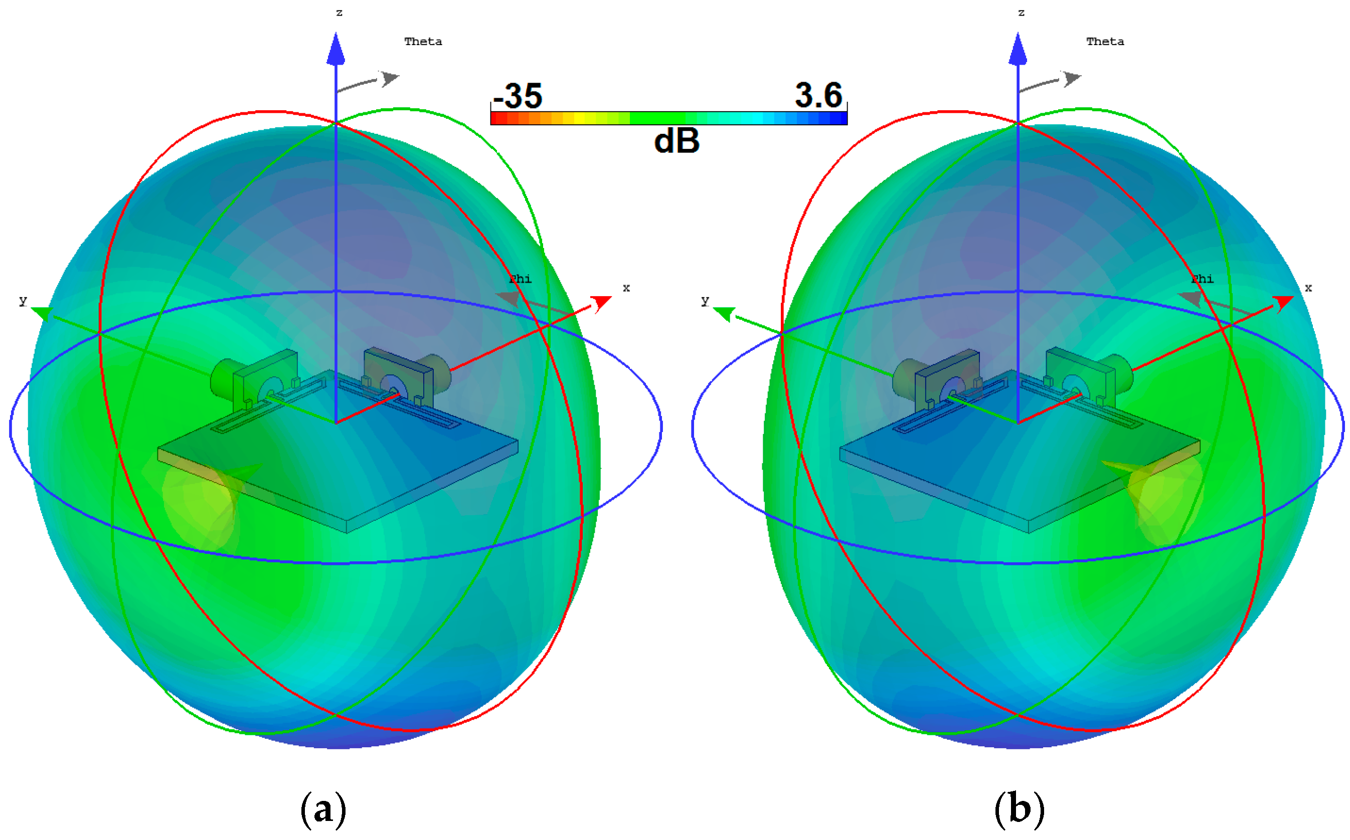
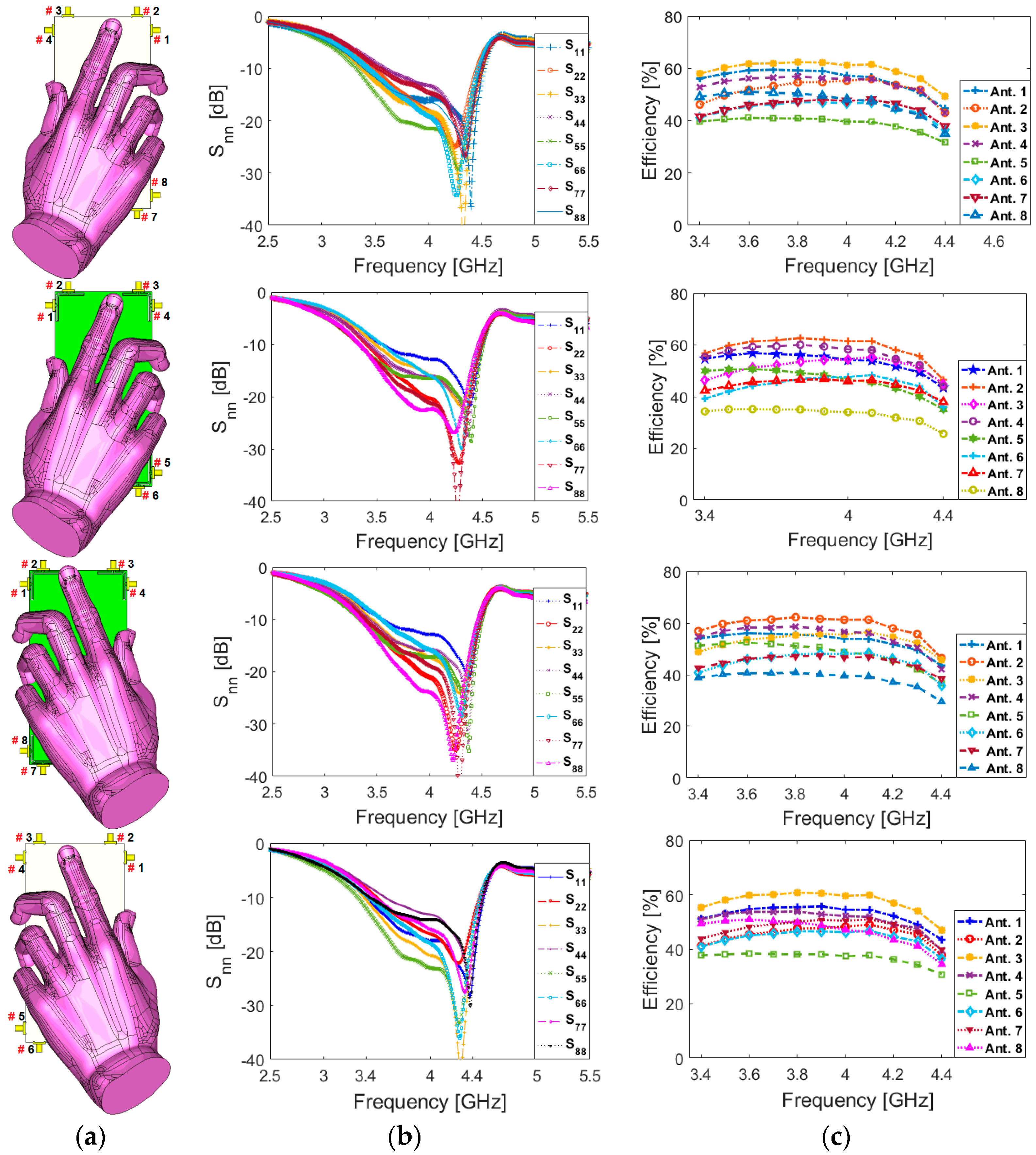
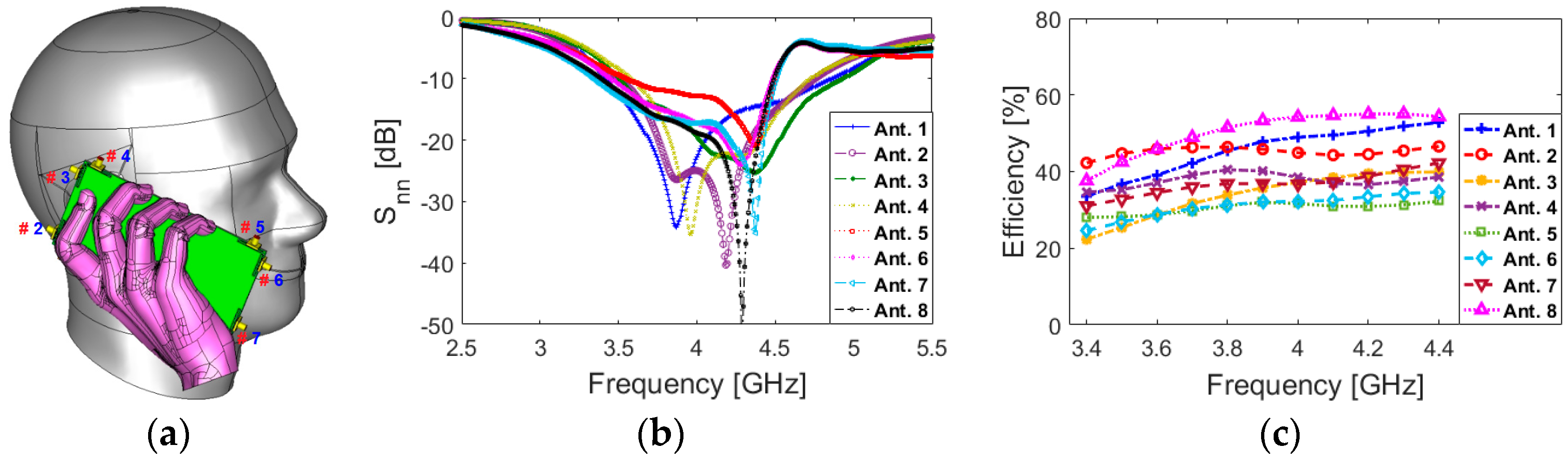
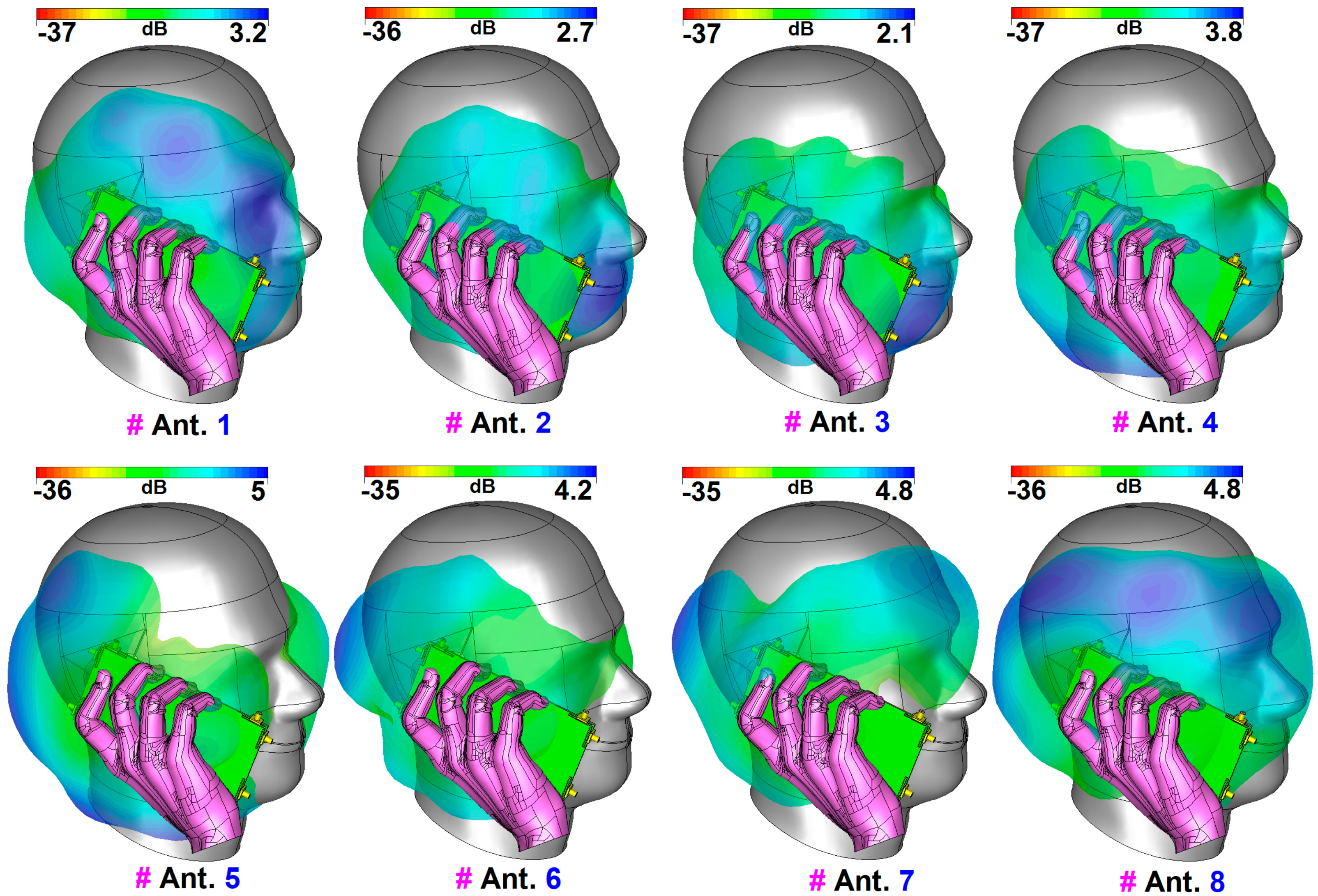
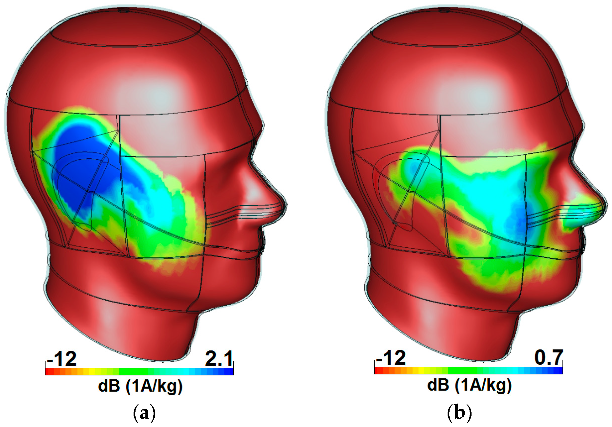
4. User Impacts on the Performance of the CPW-fed Smartphone Antenna Array

For smartphone antennas, it is indispensable to investigate the user effect on the radiation performance of the antenna [41,42]. Different usage postures in data-mode and talk-mode are considered in this section. Figure 16 represents Snn and efficiency results of the 5G antenna in data-mode with different placement modes for right/left hands touching the top/bottom sides of the smartphone. It can be observed that similar characteristics are achieved for different data-mode scenarios. This is mainly due to symmetrical configuration and similar placements of the CPW-fed antenna pairs. In addition, as shown in Figure 16b, the Snn results of all elements are not influenced significantly and still could cover the desired operation band. Some variation is discovered for the elements, which are partially covered with the hand-phantom, due to its absorption. Furthermore, it is evident from Figure 16c that a part of the radiation power of the antenna is absorbed by the medium, which causes some reduction in the efficiencies of the elements. However, the elements still provide around 40% and more total efficiencies within the 3.4–4.4 GHz operation band.
Apart from the data-mode, discussed above, the characteristics of the CPW-fed resonators in talk-mode are also investigated and represented in Figure 17, Figure 18 and Figure 19. It is evident from Figure 17 that the antenna elements work sufficiently and provide good Snn and total efficiency results for different antenna elements. The radiation pattern results for the MIMO smartphone antenna in talk-mode are shown in Figure 18. As can obviously be realized from the simulation, the proposed CPW-fed MIMO antenna offers good radiation patterns in talk-mode. In addition, the gain levels of the CPW-fed antenna resonators vary from 2 to 5 GHz.
Compared with Figure 8, the maximum reduction of antenna gain is observed for the elements closely spaced with the user’s head and hand. In general, the closer the distance between the antenna element and the user’s hand/head is, the greater the reduction on the gain and the efficiencies [43]. As can be observed, the maximum reductions of the gain levels are discovered for the elements that are located near to the head phantom (Ant. 3). In addition, due to the presence of the head and hand phantoms, the radiation patterns are a bit distorted and become weaker. One can see that antenna elements are touched by different parts of the hand and head phantoms in the presented talk-mode.
The specific absorption rate (SAR) characteristic of the CPW-fed MIMO design is studied and represented in Figure 19. It is shown that Ant. 3 causes the maximum SAR value (2.1), and the minimum SAR value (0.7) is observed from Ant. 7. Therefore, it can be concluded that the closest distance between antenna elements and the user-head leads to a maximum SAR value, and the furthest distance leads to a minimum SAR value [44,45].
The Snn (S11~S88) and efficiency characteristics of the CPW-fed MIMO smartphone antenna in the presence of battery, speaker, camera, USB connector and LCD screen are investigated and illustrated in Figure 20. It was found that the designed CPW-fed MIMO antenna provides sufficient Snn and efficiencies supporting a 3.4–4.4 GHz band. In addition, as shown in Figure 20c, the array exhibits high efficiencies in the presence of smartphone components.

5. Conclusions

A smartphone array antenna design with new double-fed CPW-fed resonators is introduced for sub-6 GHz 5G applications. The structure of the CWP-fed element consists of two closely-spaced modified T-ring radiators operating with a frequency band of 3.3–4.4 GHz. Four pairs of the CPW-fed diversity antennas are placed at four corners of the smartphone board to form an 8 × 8 MIMO antenna. The fundamental characteristics and MIMO performance of the design were studied and sufficient results were achieved. Simulated and experimental results are provided to validate the usefulness of the designed smartphone antenna array for 5G mobile communications.

Author Contributions

Writing—original draft preparation, N.O.P., Y.I.A.A.-Y., A.M.A., M.P. and R.A.A.-A.; writing—review and editing, N.O.P., H.J.B. and R.A.A.-A.; investigation, N.O.P., H.J.B., M.P. and Y.I.A.A.-Y.; resources, N.O.P., M.P. and R.A.A.-A.; for other cases, all authors have participated. All authors have read and agreed to the published version of the manuscript.

Funding

This project has received funding from the European Union’s Horizon 2020 research and innovation program under grant agreement H2020-MSCA-ITN-2016 SECRET-722424.

Acknowledgments

The authors wish to express their thanks to the support provided by the innovation program under grant agreement H2020-MSCA-ITN-2016 SECRET-722424.

Conflicts of Interest

The authors declare no conflict of interest.

References

  1. Nadeem, Q.U.A.; Kammoun, A.; Debbah, M.; Alouini, S.-M. Design of 5G full dimension massive MIMO systems. IEEE Trans. Commun. 2018, 66, 726–740. [Google Scholar] [CrossRef] [Green Version]
  2. Ojaroudiparchin, N.; Shen, M.; Pedersen, G.F. Multi-layer 5G mobile phone antenna for multi-user MIMO communications. In Proceedings of the 23rd Telecommunications Forum Telfor (TELFOR), Belgrade, Serbia, 24–26 November 2015; pp. 559–562. [Google Scholar]
  3. Osseiran, A.; Boccardi, F.; Braun, V.; Kusume, K.; Marsch, P.; Maternia, M.; Queseth, O.; Schellmann, M.; Schotten, H.; Taoka, H.; et al. Scenarios for 5G mobile and wireless communications: The vision of the METIS project. IEEE Commun. Mag. 2014, 52, 26–35. [Google Scholar] [CrossRef]
  4. Yang, H.H.; Quel, Y.Q.S. Massive MIMO Meet Small Cell. SpringerBriefs Electr. Comput. Eng. 2017. [Google Scholar] [CrossRef]
  5. Ojaroudi, N.; Ghadimi, N. Design of CPW-fed slot antenna for MIMO system applications. Microw. Opt. Technol. Lett. 2014, 56, 1278–1281. [Google Scholar] [CrossRef]
  6. Parchin, N.O.; Basherlou, H.J.; Al-Yasir, Y.I.A.; Abd-Alhameed, R.A.; Abdulkhaleq, A.M.; Noras, J.M. Recent developments of reconfigurable antennas for current and future wireless communication systems. Electronics 2019, 8, 128. [Google Scholar] [CrossRef] [Green Version]
  7. Hussain, R.; Alreshaid, A.T.; Podilchak, S.K.; Sharawi, M.S. Compact 4G MIMO antenna integrated with a 5G array for current and future mobile handsets. IET Microw. Antennas Propag. 2017, 11, 271–279. [Google Scholar] [CrossRef] [Green Version]
  8. Ojaroudi, N.; Ojaroudi, H.; Ghadimi, N. Quadband planar inverted-f antenna (PIFA) for wireless communication systems. Prog. Electromagn. Res. Lett. 2014, 45, 51–56. [Google Scholar] [CrossRef] [Green Version]
  9. Chen, Q.; Lin, H.; Wang, J.; Ge, L.; Li, Y.; Pei, T.; Sim, C.-Y.-D. Single ring slot based antennas for metal-rimmed 4G/5G smartphones. IEEE Trans. Antennas Propag 2018, 67, 1476–1487. [Google Scholar] [CrossRef]
  10. Ojaroudiparchin, N.; Shen, M.; Pedersen, G.F. Wide-scan phased array antenna fed by coax-to- microstriplines for 5G cell phones. In Proceedings of the 21st International Conference on Microwaves, Radar and Wireless Communications, krakow, Poland, 9–11 May 2016. [Google Scholar]
  11. Liu, Y.; Lu, Y.; Zhang, Y.; Gong, S.-X. MIMO antenna array for 5G smartphone applications. In Proceedings of the 13th European Conference on Antennas and Propagation (EuCAP), Krakow, Poland, 31 March–5 April 2019. [Google Scholar]
  12. Al-Hadi, A.A.; Ilvonen, J.; Valkonen, R.; Viikan, V. Eight-element antenna array for diversity and MIMO mobile terminal in LTE 3500MHz band. Microw. Opt. Technol. Lett. 2014, 56, 1323–1327. [Google Scholar] [CrossRef]
  13. Parchin, N.O.; Al-Yasir, Y.I.A.; Noras, J.M.; Abd-Alhameed, R.A. Dual-polarized MIMO antenna array design using miniaturized self-complementary structures for 5G smartphone applications. In Proceedings of the 13th European Conference on Antennas and Propagation (EuCAP), Krakow, Poland, 31 March–5 April 2019. [Google Scholar]
  14. Wong, K.-L.; Lu, J.-Y.; Chen, L.-Y.; Li, W.Y.; Ban, Y.L. 8-antenna and 16-antenna arrays using the quad-antenna linear array as a building block for the 3.5-GHz LTE MIMO operation in the smartphone. Microw. Opt. Technol. Lett. 2016, 58, 174–181. [Google Scholar] [CrossRef]
  15. Chang, L.; Yu, Y.; Wei, K.; Wang, H. Polarization-orthogonal co-frequency dual antenna pair suitable for 5G MIMO smartphone with metallic bezels. IEEE Trans. Antennas Propag. 2019, 67, 5212–5220. [Google Scholar] [CrossRef]
  16. Abdullah, M.; Ban, Y.-L.; Kang, K.; Li, M.-Y.; Amin, M. Eight-element antenna array at 3.5GHz for MIMO wireless application. Prog. Electromagn. Res. C 2017, 78, 209–217. [Google Scholar] [CrossRef] [Green Version]
  17. Zhao, X.; Yeo, S.P.; Ong, L.C. Decoupling of inverted-F antennas with high-order modes of ground plane for 5G mobile MIMO platform. IEEE Trans. Antennas Propag. 2018, 66, 4485–4495. [Google Scholar] [CrossRef]
  18. Parchin, N.O.; Al-Yasir, Y.I.A.; Ali, A.H.; Elfergani, I.; Noras, J.M.; Rodriguez, J.; Abd-Alhameed, R.A.; Al-Yasir, Y.I.A. Eight-element dual-polarized MIMO slot antenna system for 5G smartphone applications. IEEE Access 2019, 9, 15612–15622. [Google Scholar] [CrossRef]
  19. Xu, S.; Zhang, M.; Wen, H.; Wang, J. Deep-subwavelength decoupling for MIMO antennas in mobile handsets with singular medium. Sci. Rep. 2017, 7, 12162. [Google Scholar] [CrossRef] [Green Version]
  20. Sun, L.; Feng, H.; Li, Y.; Zhang, Z. Compact 5G MIMO mobile phone antennas with tightly arranged orthogonal-mode pairs. IEEE Trans. Antennas Propag. 2018, 66, 6364–6369. [Google Scholar] [CrossRef]
  21. Li, M.-Y.; Ban, Y.-L.; Xu, Z.-Q.; Guo, J.; Yu, Z.-F. Tri-polarized 12-antenna MIMO array for future 5G smartphone applications. IEEE Access 2018, 6, 6160–6170. [Google Scholar] [CrossRef]
  22. Zhao, A.; Zhouyou, R. Size reduction of self-isolated MIMO antenna system for 5G mobile phone applications. IEEE Antennas Wirel. Propag. Lett. 2019, 18, 152–156. [Google Scholar] [CrossRef]
  23. Parchin, N.O.; Basherlou, H.J.; Alibakhshikenari, M.; Parchin, Y.O.; Al-Yasir, Y.I.A.; Abd-Alhameed, R.A.; Limiti, E. Mobile-phone antenna array with diamond-ring slot elements for 5G massive MIMO systems. Electronics 2019, 8, 521. [Google Scholar] [CrossRef] [Green Version]
  24. Abdullah, M.; Kiani, S.H.; Abdulrazak, L.F.; Iqbal, A.; Bashir, M.A.; Khan, S.; Kim, S. High-performance multiple-input multiple-output antenna system for 5G mobile terminals. Electronics 2019, 8, 1090. [Google Scholar] [CrossRef] [Green Version]
  25. Jiang, W.; Liu, B.; Cui, Y.; Hu, W. High-isolation Eight-Element MIMO array for 5G smartphone applications. IEEE Access 2019, 7, 34104–34112. [Google Scholar] [CrossRef]
  26. Statement: Improving Consumer Access to Mobile Services at 3.6 GHz to 3.8 GHz. Available online: https://www.ofcom.org.uk/consultations-and-statements/category-1/future-use-at-3.6-3.8-ghz (accessed on 21 October 2018).
  27. Ojaroudi, N.; Ghadimi, N. Dual-band CPW-fed slot antenna for LTE and WiBro applications. Microw. Opt. Technol. Lett. 2014, 56, 1013–1015. [Google Scholar] [CrossRef]
  28. Ojaroudi, N. Small microstrip-fed slot antenna with frequency band-stop function. In Proceedings of the 21th Telecommunications Forum. TELFOR 2013, Belgrade, Serbia, 27–28 November 2013. [Google Scholar]
  29. Ojaroudi, N. Design of microstrip antenna for 2.4/5.8 GHz RFID applications. In Proceedings of the German Microwave Conference, GeMic 2014, RWTH Aachen University, Aachen, Germany, 10–12 March 2014. [Google Scholar]
  30. Valizade, A.; Ghobadi, C.; Nourinia, J.; Parchin, N.O.; Ojaroudi, M. Band-notch slot antenna with enhanced bandwidth by using Ω-shaped strips protruded inside rectangular slots for UWB applications. Appl. Comput. Electromagn. Soc. (ACES) J. 2012, 27, 816–822. [Google Scholar]
  31. CST Microwave Studio; ver. 2018; CST: Framingham, MA, USA, 2018.
  32. Al-Nuaimi, M.K.T.; Whittow, W.G. Performance investigation of a dual element ifa array at 3 ghz for mimo terminals. In Proceedings of the Antennas and Propagation Conference (LAPC), Loughborough, UK, 14–15 November 2011. [Google Scholar]
  33. Parchin, N.O.; Basherlou, H.J.; Abd-Alhameed, R.A.; Noras, J.M. Dual-band monopole antenna for RFID applications. Future Internet 2019, 11, 31. [Google Scholar] [CrossRef] [Green Version]
  34. Sharawi, M.S. Printed multi-band MIMO antenna systems and their performance metrics [wireless corner]. IEEE Antennas Propag. Mag. 2013, 55, 218–232. [Google Scholar]
  35. Ojaroudiparchin, N.; Shen, M.; Pedersen, G.F. Small-size tapered slot antenna (TSA) design for use in 5G phased array applications. Appl. Comput. Electromagn. Soc. J. 2018, 32, 193–202. [Google Scholar]
  36. Mazloum, J.; Ghorashi, A.; Ojaroudi, M.; Ojaroudi, N. Compact triple-band S-shaped monopole diversity antenna for MIMO applications. Appl. Comput. Electromagn. Soc. J. 2015, 30, 975–980. [Google Scholar]
  37. Ojaroudiparchin, N.; Shen, M.; Zhang, S.; Pedersen, G.F. A switchable 3-D-coverage-phased array antenna package for 5G mobile terminals. IEEE Antennas Wireless Propag. Lett. 2016, 15, 1747–1750. [Google Scholar] [CrossRef] [Green Version]
  38. Parchin, N.O.; Alibakhshikenari, M.; Basherlou, H.J.; Abd-Alhameed, R.A.; Rodriguez, J.; Limiti, E. MM-wave phased array quasi-yagi antenna for the upcoming 5G cellular communications. Appl. Sci. 2019, 9, 978. [Google Scholar] [CrossRef] [Green Version]
  39. Elfergani, I.T.E.; Hussaini, A.S.; Rodriguez, J.; Abd-Alhameed, R. Antenna Fundamentals for Legacy Mobile Applications and Beyond; Springer: Switzerland, 2017; pp. 1–659. [Google Scholar]
  40. Ojaroudi, N.; Ojaroudi, Y.; Ojaroudi, S. Compact ultra-wideband monopole antenna with enhanced bandwidth and dual band-stop properties. Int. J. RF Microw. Comput. Aided Eng. 2014, 25, 346–357. [Google Scholar] [CrossRef]
  41. Ojaroudi, N.; Yazdanifard, S.; Ojaroudi, N.; Naser-Moghaddasi, M. Enhanced bandwidth of small square monopole antenna by using inverted Ushaped slot and conductor-backed plane. Appl. Comput. Electromagn. Soc. (ACES) J. 2012, 27, 685–690. [Google Scholar]
  42. Syrytsin, I.; Zhang, S.; Pedersen, G.F. Performance investigation of a mobile terminal phased array with user effects at 3.5 GHz for LTE advanced. IEEE Antennas Wirel. Propag. Lett. 2017, 16, 1847–1850. [Google Scholar] [CrossRef] [Green Version]
  43. Ojaroudiparchin, N.; Shen, M.; Pedersen, G.F. Design of Vivaldi antenna array with end-fire beam steering function for 5G mobile terminals. In Proceedings of the 23rd Telecommunications Forum Telfor (TELFOR), Belgrade, Serbia, 24–26 November 2015; pp. 587–590. [Google Scholar]
  44. Hussain, R.; Sharawi, M.S.; Shamim, A. 4-element concentric pentagonal slot-line-based ultra-wide tuning frequency reconfigurable MIMO antenna system. IEEE Trans. Antennas Propag. 2018, 66, 4282–4287. [Google Scholar] [CrossRef]
  45. Parchin, N.O.; Ullah, A.; Asharaa, A.S.; Al-Yasir, Y.I.A.; Jahanbakhsh, H.; Nagala, M.; Abd-Alhameed, R.; Noras, J. 8×8 MIMO antenna system with coupled-fed elements for 5G handsets. In Proceedings of the IET Antennas and Propagation Conference, Birmingham, UK, 11–12 November 2019. [Google Scholar]
Figure 1. (a) Geometry of the coplanar waveguide (CPW)-fed diversity antenna and (b) its simulated S-parameters.
Electronics 09 00261 g001
Figure 2. S11/S21 results of the diversity antenna for various values of (a) W2 and (b) L2.
Electronics 09 00261 g002
Figure 3. The current densities of the diversity antenna design from port 1 at (a) 3.8 and (b) 4.2 GHz.
Electronics 09 00261 g003
Figure 4. Radiation patterns of the CPW-fed diversity antenna at 4 GHz from (a) ports 1 and (b) 2.
Electronics 09 00261 g004
Figure 5. Simulated (a) efficiency and (b) gain/directivity characteristics of the CPW-fed antenna.
Electronics 09 00261 g005
Figure 6. (a) Fabricated antenna’s top/bottom sides and (b) the simulated/measured S-parameters.
Electronics 09 00261 g006
Figure 7. Calculated (a) total active reflection coefficient (TARC), (b) envelope correlation coefficient (ECC) and (c) diversity gain (DG) characteristics of the CPW-fed diversity antenna.
Electronics 09 00261 g007
Figure 8. Schematic of the CPW-fed eight-port 5G smartphone antenna.
Electronics 09 00261 g008
Figure 9. The simulated (a) Snn and (b) Smn results.
Electronics 09 00261 g009
Figure 10. Radiation patterns of the dual-port diversity resonator from (a) port 1 and (b) port 2.
Electronics 09 00261 g010
Figure 11. 3D radiation patterns at center frequency (4 GHz).
Electronics 09 00261 g011
Figure 12. (a) Radiation and (b) total efficiencies of the antenna elements (Ant. 1–Ant. 8).
Electronics 09 00261 g012
Figure 13. (a) Front and (b) back views of the fabricated sample.
Electronics 09 00261 g013
Figure 14. (a) Feeding mechanism and (b) S-parameters of adjacent CPW-fed elements for the 5G smartphone antenna.
Electronics 09 00261 g014
Figure 15. 2D radiation patterns for (a) Ant.1 at 3.6 GHz, (b) Ant.2 at 3.6 GHz, (c) Ant.1 at 4 GHz and (d) Ant.2 at 4 GHz.
Electronics 09 00261 g015
Figure 16. (a) Placement, (b) Snn and (c) total efficiencies for different data-mode scenarios.
Electronics 09 00261 g016
Figure 17. (a) Placement, (b) Snn and (c) total efficiencies for talk-mode.
Electronics 09 00261 g017
Figure 18. Radiation patterns in Talk-Mode.
Electronics 09 00261 g018
Figure 19. Specific absorption rate (SAR) investigations for (a) Ant. 3 and (b) Ant. 7.
Electronics 09 00261 g019
Figure 20. (a) Schematic, (b) Snn and (c) efficiencies of the array in the presence of the smartphone components.
Electronics 09 00261 g020
Table 1. The dimension of the diversity antenna.
ParameterValue (mm)ParameterValue (mm)ParameterValue (mm)ParameterValue (mm)
W1.1W10.5W219Wf2.4
L7L11L22Lg0.25
Table 2. Comparison between our design and the referenced 5G smartphone antennas.
ReferenceDesign TypeBandwidth (GHz)Efficiency (%)Size
(mm2)
Isolation (dB)ECC
[11]Gap-Coupled IFA3.4–3.6-150 × 7515<0.02
[12]Inverted-F3.4–3.655–60100×5010-
[13]Patch-Slot3.55–3.6552–76150 × 7511-
[14]Monopole3.4–3.635–50150 × 7511<0.40
[15]Spatial-Reuse Antenna 3.4–3.640–70150 × 7512<0.2
[16]Inverted-L Monopole3.4–3.640–60136 × 6814<0.2
[17]Inverted-F3.4–3.6-120 × 7020-
[18]Ring-Slot3.4–3.860–75150 × 7515<0.01
[19]Monopole4.55–4.7550–70136 × 6810-
[20]Tightly Arranged Pairs3.4–3.650–70150× 7317<0.07
[21]Wave-Guide3.4–3.650–80150 × 7515<0.2
[22]Monopole3.4–3.660–70150 × 7518<0.015
[23]Diamond-shaped Slot3.3–3.960–80150 × 7517<0.01
[24]open-end slot3.4–3.650–60136 × 68110.05
[25]loop element3.3–3.640120 × 70150.02
ProposedCPW-Fed Diversity3.4–4.465–80150 × 7516<0.005

