Article

Operating-Condition-Based Voltage Control Algorithm of Distributed Energy Storage Systems in Variable Energy Resource Integrated Distribution System

Department of Electrical Engineering, Jeonbuk National University, 567 Baekje-daero, Deokjin-gu, Jeonju-si, Jeollabuk-do 54896, Korea
*
Author to whom correspondence should be addressed.
Electronics 2020, 9(2), 211; https://doi.org/10.3390/electronics9020211
Submission received: 16 December 2019 / Revised: 15 January 2020 / Accepted: 21 January 2020 / Published: 24 January 2020
(This article belongs to the Section Power Electronics)

Abstract

:
Penetration of variable energy resource (VER) is limited by voltage constraints in distribution systems. Hence, distributed energy storage systems (ESS) have been considered to be a promising solution owing to their fast and flexible control capability. This paper proposes a voltage control algorithm of the distributed ESS based on the varying operating conditions of the distribution systems. In the proposed algorithm, the required responses of the distributed ESS are controlled for regulating the monitored voltage on the distribution system by using the matched Jacobian element derived from the operating conditions as its control gain. In addition, each required response is readjusted by allocating the violated voltage to distributed ESS respectively based on the portion of its Jacobian element and its available state of charge (SoC). The effectiveness of the proposed algorithm is verified through time-series simulation by employing one of the actual distribution systems with a high penetration of VER in Korea.

1. Introduction

Recently, distribution systems have been increasingly utilizing variable energy resource (VER) as an alternative to pressure to reduce greenhouse gas emissions and depletion of fossil energy [1]. Moreover, the reduced generation cost of the VER due to technology development is expected to further increase its penetration into distribution systems in the future [2]. A small number of VERs have a negligible impact on the distribution system as their generation is smaller than the load demand of the system. However, with an increasing level of VER penetration into the system, when the generation from VER is high, it can cause various impacts ranging from voltage, loading, power quality, and malfunction of protection and control [3,4,5]. The impact is unique to the individual system, but the main challenge that limits the VER integration is overvoltage during peak generation [6,7].
Various solutions have been proposed to deal with the overvoltage of the distribution system. The most practical method is to mitigate the overvoltage by changing the set point of the tap on the secondary winding of the main transformer through on-load tap changer (OLTC), which is used to control the system voltage. However, this method has a few minutes of time delay and is limited to controlling the rapid voltage fluctuation caused by the variability and intermittency of VER generation [8,9,10]. Other methods include curtailment of VER generation during the overvoltage periods, reactive power compensation by the inverter, and increasing conductor capacity. These methods either decrease the generation efficiency of VER or are difficult to continuously reinforce according to the rapidly increasing VER integration capacity in the distribution system.
However, distributed ESS have emerged as an alternative measure to control the voltage of the distribution system as its technology has advanced and costs have decreased [11,12,13,14]. This mitigates overvoltage by charging control during peak generation of VER. In particular, because of its fast and flexible response capability, it is possible to respond to the voltage change that varies rapidly due to the VER generation. In addition, the stored energy of the distributed is discharged back into the system and hence, it does not reduce the capacity factor of the VER generation.
Various control algorithms of distributed ESS have been proposed to mitigate the overvoltage of the distribution system with a high penetration of VER. The droop-based control to calculate the required response of the distributed ESS for voltage regulation of distribution has been proposed in references [15,16]. In references [17,18], coordinated control for voltage regulation, which includes both distributed and localized controls, is proposed for distributed ESS installed in the distribution system. Those algorithms had limitations such as a fixed control gain [15], absence of the coordinated control [16], and balancing between distributed ESS without considering the operating condition of the distribution system [17,18]. However, the relationship between the charging power and the voltage reduction would continually change according to the operating conditions of the distribution system [19]. Therefore, a voltage control algorithm should be able to consider the operating conditions of the distribution system for the efficient use of the distributed ESS with the limited energy capacity to counter an overvoltage in a long-term operation. Further, state of charge (SoC) balancing is required to maintain the availability of distributed ESS which is changed by the SoC.
This paper proposes a voltage control algorithm of distributed ESS based on the varying operating conditions of the distribution systems. In the proposed algorithm, the required responses of the distributed ESS are controlled for regulating the monitored voltage on the distribution system by using the matched Jacobian element derived from the operating conditions as its control gain. In addition, each required response is readjusted by allocating the violated voltage to distributed ESS respectively based on the portion of its Jacobian element and its available SoC. By applying the proposed control algorithm of distributed ESS, the required responses of the distributed ESS can be determined considering the operating conditions of the distribution system and its availability can be maximized by balancing those charging powers and SoC. The effectiveness of the proposed algorithm is verified through a time-series simulation by employing one of the actual distribution systems with a high penetration of VER in Korea.

2. Application of Distributed ESS on the VER Integrated Distributed System

2.1. Voltage Constraint in the VER Integrated Distribution System

Among the various impacts of VER on the distribution system, overvoltage, thermal overloading, electrical power loss, power quality, and protection problem are the factors that affect the distribution system operation [4]. The main challenge is that the overvoltage caused by the VER generation can limit its integrated capacity in the distribution system [6]. A typical distribution system consists of multiple buses, as illustrated in Figure 1, and its voltage profile depends on both the magnitude and direction of the power flow.
In a distribution system without VER, the load demand is met by the power supplied from substations to customers. The power flow is generally unidirectional. Because of this feature, the voltage profile has a decreasing trend caused by the line impedance and load demand from the substation to the ends of the feeder. To manage the distribution system with this decreasing voltage profile trend, most systems have been operated considering voltage drop at the end of the feeder by using OLTC. Nevertheless, after integrating the VER into the distribution system, the VER generation ( P V E R ) compensates the supplied power to the substation and counters the voltage drop. When the integrated VERs increase in the distribution system, P V E R can exceed the load demand and it can induce reverse power flow. As a result, the voltage in the distribution system can be further increased, which can lead to overvoltage.
Overvoltage is considered one of the important factors for operating the distribution system with VER in Korea. Korea Electric Power Corporation (KEPCO) stipulates that evaluating the impact of the system on the voltage is necessary to integrate the VER into the distribution system. Figure 2 shows the evaluation flow chart for integrating VER in a distribution system [20].
In this voltage evaluation procedure, several data of the distribution system need to be set for the power flow calculation, including load demand, secondary voltage of the main transformer, and VER generation, based on previous operation data. The load demand and the VER generation are set to the average of the lower 5% of the operation data and rated power, respectively, and the secondary voltage of the main transformer is set to the average of the operation data. Based on these assumed conditions, the power flow of the system is calculated. Through this procedure, the integration of VER is only acceptable when the voltage ( V D / L ) does not exceed its upper limit ( V m a x ) . For example, Figure 3 shows the result of voltage evaluation on the distribution system with high VER penetration in Korea.
As a result of the voltage evaluation of this distribution system, as the distance from the main transformer increases, each node and VER has higher voltage and the end of feeder exhibits maximum voltage. Violation of the voltage limit starts from the middle of the feeder, which means that the voltage problem could become severe and the VERs could be saturated from that point. This overvoltage should be mitigated for integrating the VER into the distribution system.

2.2. Considerations in Distributed ESS Application

One of the various solutions for voltage control is that the distributed ESS can effectively contribute to the operation of the distribution system with high penetration of the VER by using its fast and flexible control capability. From these characteristics, this paper assumed the type of the distributed ESS as the lithium-ion based battery energy storage system (BESS), which is widely used for frequency regulation and voltage control in Korea. The overvoltage of the distribution system can be mitigated by absorbing the VER generation with the distributed ESS. However, the effectiveness of mitigated voltage from distributed ESS can be different depending on operating conditions such as load demand, VER generation, and connection point. Figure 4 shows the voltage sensitivity of active power from each bus to the voltage at the end of the feeder in the simulation operating system from Figure 1. It is derived from the reduced voltage by charging the active power of the unit capacity on each bus by a single distributed ESS.
This voltage sensitivity is significantly affected by system operating conditions, such as the load demand and VER generation. Because these system operating conditions are changed depending on the time, the voltage sensitivity is different at each hour. Furthermore, the level of voltage sensitivity is determined by the connection point of the distributed ESS. Therefore, absorbing more power would be required by a distributed ESS with low voltage sensitivity to reduce the same amount of voltage at the end of the feeder. As a result of this control, the SoC of distributed ESS could be managed differently depending on the connection points. Further, the duration time of the distributed ESS for voltage control can also be different. Figure 5 shows the charging power for each ESS estimated based on the voltage sensitivity to mitigate 1 V per hour at the end of the feeder in the simulation operating system from Figure 1. At this time, the same energy constraint is considered for all distributed ESS.
Although the distributed ESS at each connection point control the identical voltage at the end of the feeder, their charging powers are different according to those voltage sensitivities. More charging power is required for the distributed ESS at the connection point with low voltage sensitivity. As a result, the SoC of that distributed ESS can be saturated early and excluded from the voltage control to decrease the availability of distributed ESS.
Thus, this paper proposes the determining control requirement of the distributed ESS by applying voltage sensitivity considering the operating conditions of the distribution system. Furthermore, this paper also considers the weighting coefficients of the distributed ESS to maximize their availability.

3. Control Algorithm of the Distributed ESS

The objective of this paper is to propose a voltage control algorithm for distributed ESS based on the operating conditions of the distribution system for overvoltage mitigation. The voltage control algorithm should possess a central controller for calculating the control requirement to the distributed ESS with the distribution system information. There must be realistic constraints for implementing the proposed control algorithm, but this paper is focused on developing the algorithm for controlling the distributed ESS. Those constraints could be relieved if the effectiveness of the proposed algorithm is verified. In addition, in this paper, only the minimum set of the data is assumed to be available from the distribution system. The control structure assumed for voltage control with the distributed ESS is shown in Figure 6. It is assumed that reactive power control is not used in the control scheme.
The central controller acquires the operation information ( P t , Q t , | V t | , θ t ) of buses on the distribution system in real-time. Here, P t is the active power, Q t is the reactive power, | V t | is the voltage magnitude, and θ t is the voltage angle at t hour. When the voltage exceeds the upper limit at the j bus, the violated voltage is calculated by Equation (1):
V v i o l a t e d , j t = V j t V t h r c ,
where V v i o l a t e d , j t is the violated voltage of the j bus, V j t is the voltage of the j bus, and V t h r c is the charging control threshold voltage.
This V v i o l a t e d , j t would be mitigated through the charging control of the distributed ESS for securing the voltage of the system within the operating range. In the control algorithm, V v i o l a t e d , j t is allocated to the individual distributed ESS considering its constraints. To mitigate this allocated value ( V j i t ) , the control gain ( k i t ) is applied to calculate the charging power ( P c h , i t ) of the distributed ESS at i bus. The time response of the distributed ESS is within 200 ms even if communication delays are included. Because this time response is very small compared to the simulation time step of one hour, this study did not consider the time response. Further, in a radial distribution system, it is typical to have the highest or lowest voltage on the end of the feeder depending on the operating condition. Therefore, if the voltage at the end of the feeder is within the operating range, the whole distribution system could meet the voltage criteria. Hence, in this study, the bus on the end of the feeder is monitored to control the voltages using the distributed ESS.

3.1. Control Gain Based on Jacobian Matrix

In the proposed algorithm, the required response of the distributed ESS for controlling the voltage on the remote bus is calculated using the Jacobian matrix, which is a classical approach to calculate the voltage sensitivity [21,22]. The Jacobian inverse matrix ( J 1 ) is composed of the sensitivities of a system at a given operating point as shown in Equation (2).
J 1 = [ θ P   θ Q | V | P   | V | Q ]
However, the above method requires real-time information on all buses of the distribution system to be considered for its time-varying operating conditions. Hence, numerous measurements and communication infrastructures are necessary, but the requirements are highly expensive [23,24]. To obtain voltage sensitivity under the limited measurements, this study proposes a system reduction as shown in Figure 7.
The purpose of the reduction is to calculate the Jacobian Matrix from the minimum bus information necessary to derive the voltage sensitivity of the bus that is connected to the distributed ESS to the end of the feeder. Therefore, the distribution system could be reduced to simplify the model of the secondary side of the main transformer, the end of the feeder, and the connection points of the distributed ESS as an equivalent circuit. In addition, the voltage sensitivities of the distributed ESS are assumed to be calculated based on the system operating conditions before the one-time step considering the communication time delay of the controller.
Therefore, the required response for distributed ESS can be calculated by using Equation (3) to mitigate the overvoltage of the distribution system.
P c h , i t = 1 s j i t 1 × V j i t
where P c h , i t is the required response of the distributed ESS at the i bus, s j i t 1 is a part of the | V | P in the Jacobian Matrix, and is the voltage sensitivity of the active power on i bus to the voltage on j bus based on the operating conditions just before the one-time step, and V j i t is the voltage to be controlled on j bus.

3.2. Charging Power Balancing of the Distributed ESS

For coordinating the responses of the distributed ESS, the violation of the voltage on the monitored bus is allocated to each ESS. Moreover, the required responses of the distributed ESS are balanced for maximizing the availability by allocating the voltage violation to the distributed ESS proportional to the voltage sensitivity. As the weighting coefficient ( ε i t ) is defined to consider the voltage sensitivity of the distributed ESS, ε i t and V j i t can be calculated by Equations (4) and (5), respectively:
ε i t = s j i t 1
V j i t = ε i t i = 1 n ε i t × V v i o l a t e d , j t
where ε i t is the weighting coefficient at time t . V j i t is then determined by the normalized ε i t and the required responses from the distribute ESS calculated by Equation (3) are balanced.

3.3. SoC Balancing of the Distributed ESS

To ensure the availability of distributed ESS for voltage control, it is also necessary to balance their SoC. In this voltage control algorithm, the SoC of the distributed ESS is balanced by readjusting the required responses proportionally to the available SoC. To consider the available SoC of the distributed ESS, an additional weighting coefficient ( μ i t ) based on SoC dispersion is defined that can be calculated by Equations (6) and (7):
S o C a v g t = i = 1 n S o C i t n
μ i t = { 1 + a × S o C a v g t S o C i t 100 ,     S o C i t < SoC m a x 0 ,     S o C i t SoC m a x
where a is a constant value which affects the convergence speed and control accuracy. It is assumed to be 10 in this study. It should be noted that if an SoC of one of the specific distributed ESS is saturated, the distributed ESS will be removed from the voltage control process by assigning the μ i t to be 0.
Finally, the V j i t are calculated by the normalized product of two weighting coefficients for the required responses that are balanced by the voltage sensitivity to be readjusted.
V j i t = ε i t × μ i t i = 1 n ( ε i t × μ i t ) × V v i o l a t e d , j t

3.4. Availability Recovery Control

As the distributed ESS are usually charged to resolve the overvoltage occurring on the VER integrated distribution system, the availability needs to be secured by discharging them whenever appropriate. However, any impact of this discharging on the operation of the distributed system should be minimized.
In the proposed algorithm, as the VER integrated into the distribution system is assumed to be photovoltaic (PV) (these are mostly installed in Korea), the distributed ESS are discharged evenly during the night. Moreover, the discharging power of each ESS is controlled to minimize its impact on the distribution system by discharging distributed ESS using the maximum time allowed. Equation (9) represents the discharging power of distributed ESS,
P d i s , i = S o C i S o C m i n , i t d i s / C r a t e , i
where t d i s is discharging time duration and it is set to be 8 h from 22:00 h to 06:00 h on the next day. C r a t e , i is C-rate of the ESS connected to i bus.

4. Case Study

4.1. Distribution System Data and Description

The verification of voltage control can be based on the voltage being managed below the voltage limit despite the high VER penetration in the distribution system. Hence, a simulation is conducted to evaluate the performance of the proposed voltage control from distributed ESS by using OpenDSS (Open Distribution System Simulator) from EPRI (Knoxville, Tennessee, USA), which is a widely used simulation tool in distribution system analysis. Moreover, Matlab is used as the application program interface (API) with OpenDSS. In this study, the specific distribution system model which has the highest penetration of VER in Korea is applied as observed in Figure 8.
The distribution system supplies the peak demand of 6.5 MW by 45-kVA, 154/22.9 kV transformer. The power factor of the demand is assumed to be 0.9, which is used by the KEPCO for the analysis of the distribution system. In addition, it is composed of three types of cables as described in Table 1 with a total length of 30 km.
In the case of VERs in this system model, 72 sites of VERs with a total capacity of 25 MW are integrated and they are operated with a unity power factor. In addition, the profile of load demands and VERs generation are considered using 2017 historical data of this system model to verify the methodology under realistic conditions as shown in Figure 9.
It is observed from Figure 9 that the load demand and VERs generation show continuous fluctuation every hour, which can lead to voltage problems in the distribution system. When the VERs generation exceeds the load demand in the distribution system, overvoltage is induced. To prevent these constraints, five of the distributed ESS are modelized in this distribution system with specifications described in Figure 5 and 10%~90% of the SoC operating range.
In this study, the upper voltage limit is set to 1.02 p.u. as per the guideline of KEPCO for integrating VER into the distribution system. In addition, it is necessary to set a specific threshold voltage for triggering the control to secure the voltage within the operating limit. Therefore, in the proposed control algorithm, the upper threshold voltage is set to 1.018 p.u., which is 10% stronger than the voltage limit required in the system.

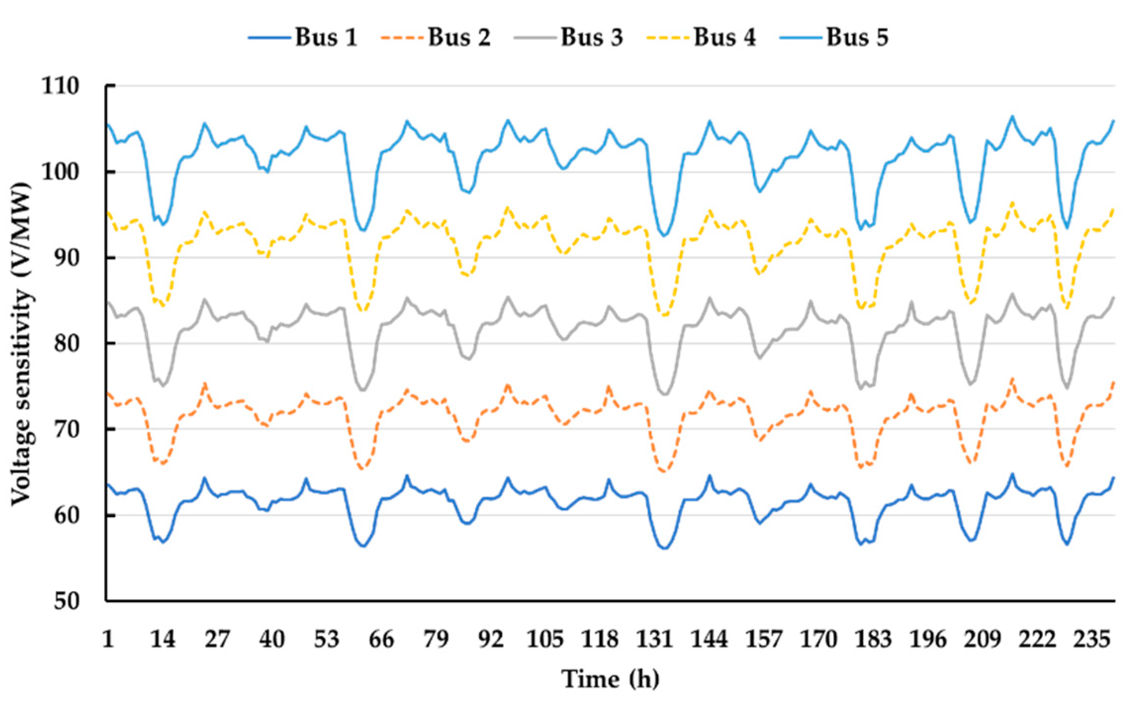
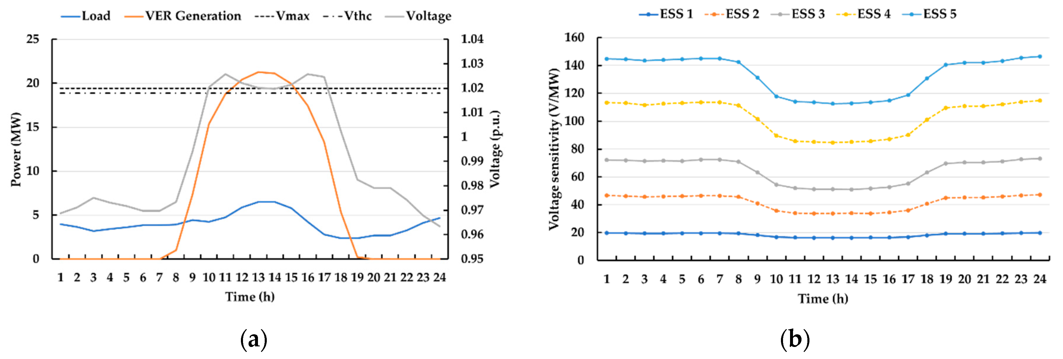
4.2. Verification of Proposed Voltage Sensitivity Derivation Method

To verify the proposed voltage sensitivity derivation method, the derived voltage sensitivity is analyzed by comparing the voltage sensitivity obtained by charging from distributed ESS through annual time-series simulation. Figure 10 shows the annual voltage sensitivity based on the proposed method.
The voltage sensitivity of each ESS is altered every hour depending on the operating condition in the distribution system; the level of which is different for each connection point. The minimum voltage sensitivity (16 V/MW) and the maximum voltage sensitivity (150 V/MW) are experienced at ESS 1 and ESS 5, respectively. This implies that the voltage sensitivity is different up to 134 V/MW depending on the operating conditions of the distribution system; therefore, the control gain of distributed ESS should be set based on the operating conditions.
Therefore, the accurate estimation of voltage sensitivity is important to set the effective control gain for determining the required responses. Further, the accuracy of the voltage sensitivity from the proposed method is verified as the deviation of the voltage sensitivities, as demonstrated in Figure 11 and Table 2.
Figure 11 shows that the distributions of the voltage sensitivity deviation vary depending on the connection points of distributed ESS but that the average values are similar. As observed in Table 2, the average of the voltage sensitivity deviation is lower than 4 V/MW in all connection points and the maximum value belonging to the ±3σ interval is 24.28 V/MW, which is a very small value compared to the 13.22 kV of rated voltage. Thus, the accuracy of the proposed voltage sensitivity derivation method is verified from the results.

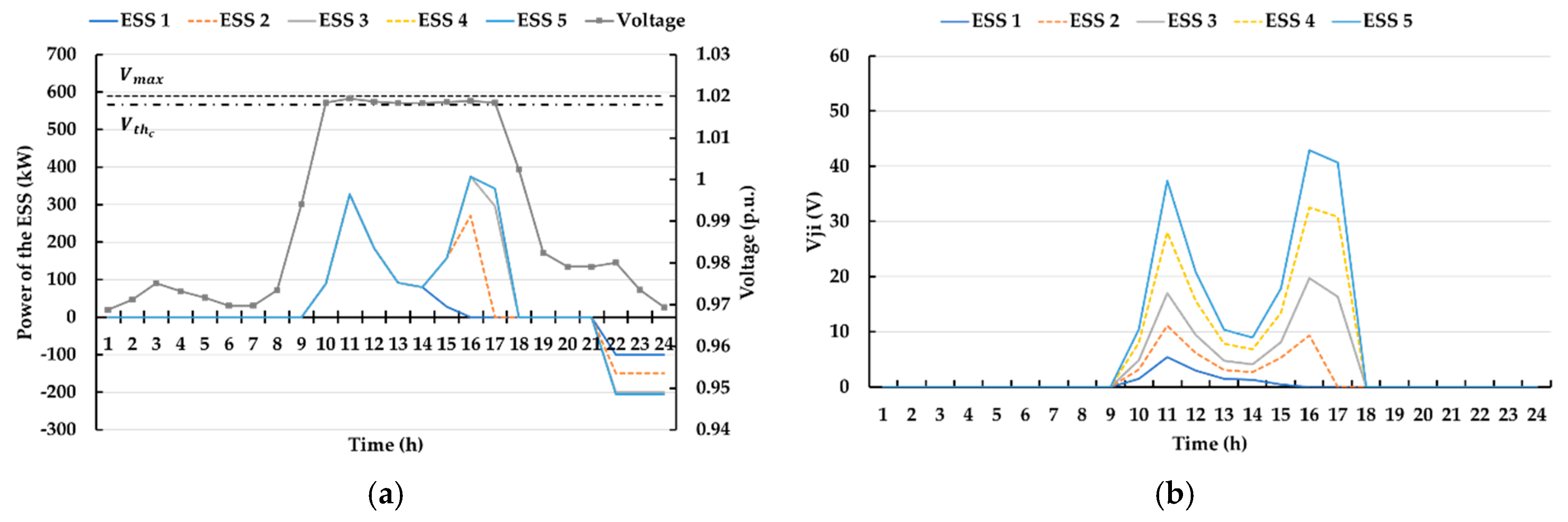
4.3. Verification of the Voltage Control Algorithm of Distributed ESS

Verifying the effectiveness of the voltage control algorithm considering operating conditions is important when the distributed ESS are operated in the distribution system to maximize its availability. The proposed voltage control algorithm is verified with the daily data of the highest VERs generation as shown in Figure 12.
Initially, when the VERs generation is higher than the load demand, the distribution system experiences overvoltage for 8 h from 10:00 h to 16:00 h. As mentioned earlier, the voltage sensitivity of each ESS changes depending on the system operating conditions.
To mitigate the overvoltage during high VERs generation, the proposed voltage control algorithm is applied to distributed ESS based on the operating conditions of the system. To verify the effectiveness of the proposed voltage control algorithm, the voltage control results from identical V j i t are considered before considering the weighting coefficients as shown in Figure 13.
Figure 13a shows the voltage profile in the distribution system and the power of distributed ESS. Before the occurrence of overvoltage, the charging power from distributed ESS is idle for 9 h. After the voltage of the distribution system exceeds the charging threshold voltage, distributed ESS are activated to provide the charging control between 10:00 and 17:00 h. The voltage is then mitigated to be lower than the upper voltage limit. Because the weighting coefficients are not considered, V j i t is identically allocated to each ESS when the SoC is sufficient for voltage control. For example, at 10:00 h, V j i t from ESS 1 to ESS 5 were identical at 5.63 V and at 11:00 h, V j i t from ESS 2 to ESS 5 were identical at 22.83 V. However, as the voltage sensitivity is different depending on the connection point, the charging power is different even if V j i t are identical as observed in Figure 13a,b. As a result, the available power capacity for voltage control decreases rapidly to 1027 kW as shown in Figure 13c. This drawback can be improved by allocating the voltage violation to the distributed ESS proportional to the voltage sensitivity as shown in Figure 14.
The primary goal of this control is to balance the required response for all distributed ESS during the operation time. In this simulation, the V j i t is allocated proportionally to the voltage sensitivity under the same conditions as in the previous simulation, i.e., the larger the voltage sensitivity of the distributed ESS, the more V j i t is allocated in voltage control as shown in Figure 14b. Here, if the available SoC is sufficient, the required responses of distributed ESS are identical as shown in Figure 14a. As a result, the minimum available power capacity for voltage control is increased to 1108 kW.
To further ensure the availability of the distributed ESS, SoC is balanced by readjusting the required responses proportionally to the available SoC as shown in Figure 15.
In this control, μ i t is applied to SoC balancing of the distributed ESS. Figure 15a,b show the power and V j i t of the distributed ESS, respectively. In comparison to Figure 14a,b, the larger SoC of the distributed ESS, more V j i t is allocated and more charging power is provided in voltage control. For example, the charging power of the distributed ESS at 11:00 h is identical when considering only the ε i t , but additional consideration of the μ i t shows that the charging power is increased in the order of the distributed ESS with more available SoC. The SoC profile and available power capacity for voltage control are shown in Figure 15c. It is observed that the minimum available power capacity for voltage control is increased to 1409 kW after SoC balancing. As a result, the minimum power capacity for voltage control is increased by 37%, i.e., from 1027 kW to 1409 kW.

4.4. Effect of the Voltage Control Algorithm of the Distributed ESS

The effect of the above voltage control algorithm and the results of the annual simulations are presented in Figure 16.
In the annual simulation results, overvoltage is observed through a maximum voltage of 1.03 p.u. for 546 h. Further, the overvoltage is mitigated within the operating range through the voltage control from the distributed ESS as observed in Figure 16a. Here, the control gain of the distributed ESS changes, as shown in Figure 16b. It is observed that the control gain of the distributed ESS is set appropriately with the use of voltage sensitivity. In addition, considering the weighting coefficients, a saturation of a specific distributed ESS with low voltage sensitivity is prevented by charging power balancing control and SoC balancing control. This resulted in an increase of the available power capacity for voltage control as observed in Figure 16c,d.

5. Conclusions

This paper proposed a voltage control algorithm of the distributed ESS based on the varying operating conditions of the distribution systems with high VER penetration. The proposed algorithm maximizes the availability of the distributed ESS and supports the hosting capacity of the distribution system for integrating VER. The proposed algorithm calculates the voltage sensitivity of each ESS to the monitored voltage using the matched Jacobian element from the operating conditions of the distribution system. The required responses of the distributed ESS are calculated by allocating any voltage violation using its voltage sensitivity. The required responses are readjusted based on each state of charge (SoC) so that the power outputs and SoCs of distributed ESS are balanced to maximize the availability. The algorithm’s effectiveness is verified through time-series simulation by employing one of the actual distribution systems with a high penetration of VER in Korea. Through the case studies it could be found that the proposed algorithm regulates the voltage of the distribution system within operating range and, moreover, prevents the saturation of the SoC despite the varying specifications of the distributed ESS. It is expected that the hosting capacity of the distribution system for integrating VER can be increased by applying distributed ESS with the proposed algorithm in Korea. Moreover, as the configuration of the distribution system assumed to be radial in this paper seems likely to change in the future, the application of the proposed algorithm needs to be considered on more general distribution systems in future study. A demonstration project is prepared for testing the algorithm’s effectiveness in a real operation.

Author Contributions

Methodology, S.G.N., W.Y.C. and K.S.K.; software, S.G.N.; validation, S.G.N. and K.S.K.; investigation, S.G.N.; writing—original draft preparation, S.G.N, W.Y.C. and K.S.K.; writing—review and editing, S.G.N., W.Y.C. and K.S.K.; supervision, K.S.K. All authors have read and agreed to the published version of the manuscript.

Funding

This research was funded by Korea Electric Power Corporation, grant number R18XA04.

Acknowledgments

This research was supported by the Korea Electric Power Corporation (grant number: R18XA04).

Conflicts of Interest

The authors declare no conflict of interest.

References

  1. UNFCC. Paris Agreement. In Proceedings of the Conference of the Paris; UNFCC: New York, NY, USA, 2015. [Google Scholar]
  2. REN21. Renewables 2015 Global Status Report; REN21: Paris, France, 2015. [Google Scholar]
  3. Lopes, J.P.; Hatziargyriou, N.; Mutale, J.; Djapic, P.; Jenkins, N. Integrating distributed generation into electric power systems: A review of drivers, challenges and opportunities. Electr. Power Syst. Res. 2007, 77, 1189–1203. [Google Scholar] [CrossRef] [Green Version]
  4. Ismael, S.M.; Aleem, S.H.A.; Abdelaziz, A.Y.; Zobaa, A.F. State-of-the-art of hosting capacity in modern power systems with distributed generation. Renew. Energy 2019, 130, 1002–1020. [Google Scholar] [CrossRef]
  5. Mohammadi, P.; Mehraeen, S. Challenges of PV integration in low-voltage secondary networks. IEEE Trans. Power Deliv. 2017, 32, 525–535. [Google Scholar] [CrossRef]
  6. Smith, J. Stochastic Analysis to Determine Feeder Hosting Capacity for Distributed Solar PV; EPRI Tech: Palo Alto, CA, USA, 2012; pp. 1–50. [Google Scholar]
  7. Ding, F. On distributed PV hosting capacity estimation, sensitivity study, and improvement. IEEE Trans. Sustain. Energy 2017, 8, 1010–1020. [Google Scholar] [CrossRef]
  8. Kim, B.; Ryu, K.S.; Kim, D.J.; Jang, M.S.; Ko, H.S.; Rho, D. Optimal operation method and capacity of energy storage system in primary feeders with step voltage regulator. J. Korea Acad. Ind. Coop. Soc. 2018, 19, 9–20. [Google Scholar]
  9. Kim, B.; Nam, Y.H.; Ko, H.; Park, C.H.; Kim, H.C.; Ryu, K.S.; Kim, D.J. Novel voltage control method of the primary feeder by the Energy Storage System and Step Voltage Regulator. Energies 2019, 12, 3357. [Google Scholar] [CrossRef] [Green Version]
  10. Kim, M.; Hara, R.; Kita, H. Design of the optimal ULTC parameters in distribution system with distributed generations. IEEE Trans. Power Syst. 2009, 24, 297–305. [Google Scholar]
  11. Wang, L.; Liang, D.H.; Crossland, A.F.; Taylor, P.C.; Jones, D.; Wade, N.S. Coordination of multiple energy storage units in a low-voltage distribution network. IEEE Trans. Smart Grid 2015, 6, 2906–2918. [Google Scholar] [CrossRef] [Green Version]
  12. Zarrilli, D.; Giannitrapani, A.; Paoletti, S.; Vicino, A. Energy storage operation for voltage control in distribution networks: A receding horizon approach. IEEE Trans. Control Syst. Technol. 2018, 26, 599–609. [Google Scholar] [CrossRef]
  13. Wong, L.A.; Ramachandaramurthy, V.K.; Taylor, P.; Ekanayake, J.B.; Walker, S.L.; Padmanaban, S. Review on the optimal placement, sizing and control of an energy storage system in the distribution network. J. Energy Storage 2019, 21, 489–504. [Google Scholar] [CrossRef]
  14. Hua, Y.; Shentu, X.; Xie, Q.; Ding, Y. Voltage/frequency deviations control via distributed battery energy storage system considering state of charge. Appl. Sci. 2019, 9, 1148. [Google Scholar] [CrossRef] [Green Version]
  15. Von Appen, J.; Stetz, T.; Braun, M.; Schmiegel, A. Local voltage control strategies for PV storage systems in distribution grids. IEEE Trans. Smart Grid 2014, 5, 967–977. [Google Scholar] [CrossRef]
  16. Kabir, M.N.; Mishra, Y.; Ledwich, G.; Dong, Z.Y.; Wong, K.P. Coordinated control of grid-connected photovoltaic reactive power and battery energy storage systems to improve the voltage profile of a residential distribution feeder. IEEE Trans. Ind. Inform. 2004, 10, 967–977. [Google Scholar] [CrossRef]
  17. Wang, Y.; Tan, K.T.; Peng, X.Y.; So, P.L. Coordinated control of distributed energy storage systems for voltage regulation in distribution networks. IEEE Trans. Power Deliv. 2006, 31, 1132–1141. [Google Scholar] [CrossRef]
  18. Zeraati, M.; Golshan, M.E.H.; Guerrero, J.M. Distributed control of battery energy storage systems for voltage regulation in distribution networks with high PV penetration. IEEE Trans. Smart Grid 2018, 9, 3582–3593. [Google Scholar] [CrossRef] [Green Version]
  19. Pachanapan, P.; Anaya-Lara, O.; Dysko, A.; Lo, K.L. Adaptive zone identification for voltage level control in distribution networks with DG. IEEE Trans. Smart Grid 2012, 3, 1594–1602. [Google Scholar] [CrossRef]
  20. Korean Electric Power Corporation (KEPCO). Technical Guideline for Connecting Distributed Generator to Distribution System; KEPCO: Naju, Korea, April 2018. [Google Scholar]
  21. Peschon, J.; Piercy, D.S.; Tinney, W.F.; Tveit, O.J. Sensitivity in power systems. IEEE Trans. Power Appar. Syst. 1968, PAS-87, 1687–1696. [Google Scholar] [CrossRef]
  22. Begovic, M.M.; Phadke, A.G. Control of voltage stability using sensitivity analysis. IEEE Trans. Power Syst. 1992, 7, 114–123. [Google Scholar] [CrossRef]
  23. Zhang, Z.; Ochoa, L.F.; Valverde, G. A novel voltage sensitivity approach for the decentralized control of DG plants. IEEE Trans. Power Syst. 2018, 33, 1566–1576. [Google Scholar] [CrossRef] [Green Version]
  24. Christakou, K.; LeBoudec, J.Y.; Paolone, M.; Tomozei, D.C. Efficient computation of sensitivity coefficients of node voltages and line currents in unbalanced radial electrical distribution networks. IEEE Trans. Smart Grid 2013, 4, 741–750. [Google Scholar] [CrossRef] [Green Version]
Figure 1. Distribution system with multiple buses.
Electronics 09 00211 g001
Figure 2. Voltage evaluation for integrating the variable energy resource (VER) into the distribution system.
Electronics 09 00211 g002
Figure 3. Voltage profile on one of the feeders in the Korea distribution system.
Electronics 09 00211 g003
Figure 4. Voltage sensitivity to the end of the feeder for each bus.
Electronics 09 00211 g004
Figure 5. Operational data of the distributed energy storage systems (ESS): (a) Charging power; (b) state of charge (SoC) profile.
Electronics 09 00211 g005
Figure 6. The control structure of the voltage control algorithm of the distributed ESS.
Electronics 09 00211 g006
Figure 7. Concept of system reduction method.
Electronics 09 00211 g007
Figure 8. Distribution system model.
Electronics 09 00211 g008
Figure 9. Annual data: (a) Load demand; (b) VER generation.
Electronics 09 00211 g009
Figure 10. Voltage sensitivity based on the proposed method.
Electronics 09 00211 g010
Figure 11. Distributions of voltage sensitivity deviation.
Electronics 09 00211 g011
Figure 12. Daily data with the highest generation of VER: (a) Load demand, VER generation, and voltage; (b) Voltage sensitivity.
Electronics 09 00211 g012
Figure 13. Voltage control results without ε , μ : (a) Voltage profile and power of the distributed ESS; (b) V j i t ; (c) SoC profile.
Electronics 09 00211 g013
Figure 14. Voltage control results with ε : (a) Voltage profile and power of the distributed ESS; (b) V j i t ; (c) SoC profile.
Electronics 09 00211 g014aElectronics 09 00211 g014b
Figure 15. Voltage control results with ε , μ : (a) Voltage profile and power of the distributed ESS; (b) V j i t ; (c) SoC profile.
Electronics 09 00211 g015
Figure 16. Annual simulation results: (a) Voltage profile; (b) Control gain of distributed ESS; (c) SoC profiles; (d) Available power of the distributed ESS.
Electronics 09 00211 g016
Table 1. Cable data used for the distribution system.
Conductor Resistance   ( Ω / k m ) Reactance   ( Ω / k m )
CNCV-W3250.0750.125
AWOC-1600.3040.441
AWOC-950.1820.391
Table 2. 3-Sigma value of voltage sensitivity deviation depending on the connection point of ESS.
Voltage SensitivityESS 1 (V/MW)ESS 2 (V/MW)ESS 3 (V/MW)ESS 4 (V/MW)ESS 5 (V/MW)
Avg.0.740.350.721.793.29
3 σ −6.67−12.43−15.73−17.91−17.71
+ 3 σ 8.1513.1417.1721.4824.28

