Article

Max-Min Fairness and Sum Throughput Maximization for In-Band Full-Duplex IoT Networks: User Grouping, Bandwidth and Power Allocation

by
Ngo Tan Vu Khanh
1,* and
Van Dinh Nguyen
2
1
Department of Ecommerce Technology, School of Business Information Technology, University of Economics Ho Chi Minh City, Ho Chi Minh City 70000, Vietnam
2
Institute of Research and Development, Duy Tan University, Da Nang 550000, Vietnam
*
Author to whom correspondence should be addressed.
Electronics 2020, 9(12), 2182; https://doi.org/10.3390/electronics9122182
Submission received: 16 November 2020 / Revised: 9 December 2020 / Accepted: 14 December 2020 / Published: 18 December 2020
(This article belongs to the Special Issue Access Technology in 5G and Mobile Communication Networks)

Abstract

:
The skyrocketing growth in the number of Internet of Things (IoT) devices has posed a huge traffic demand for fifth-generation (5G) wireless networks and beyond. In-band full-duplex (IBFD), which is theoretically expected to double the spectral efficiency of a half-duplex wireless channel and connect more devices, has been considered as a promising technology in order to accelerate the development of IoT. In order to exploit the full potential of IBFD, the key challenge is how to handle network interference (including self-interference, co-channel interference, and multiuser interference) more effectively. In this paper, we propose a simple yet efficient user grouping method, where a base station (BS) serves strong downlink users and weak uplink users and vice versa in different frequency bands, mitigating severe network interference. First, we aim to maximize a minimum rate among all of the users subject to bandwidth and power constraints, which is formulated as a nonconvex optimization problem. By leveraging the inner approximation framework, we develop a very efficient iterative algorithm for solving this problem, which guarantees at least a local optimal solution. The proposed iterative algorithm solves a simple convex program at each iteration, which can be further cast to a conic quadratic program. We then formulate the optimization problem of sum throughput maximization, which can be solved by the proposed algorithm after some slight modifications. Extensive numerical results are provided to show not only the benefit of using full-duplex radio at BS, but also the advantage of the proposed user grouping method.

1. Introduction

By 2023, it is estimated that the number of Internet of Things (IoT) devices will be 29.3 billions with a connection density of one-million devices per km2 [1]. In addition, the global mobile data traffic is projected to reach 49 exabytes per month in 2021, in which the IoT related data are the main driving force. These numbers are tremendous and will further increase over the coming years. It is clear that the successful deployment of IoT are expected to enable many crucial applications, including Financial Technology (FinTech) services, factory automation, and remote surgery, to name a few [2,3]. In order to meet the aforementioned demands and accelerate the roll-out of the IoT, the industry and academic communities are currently investigating promising physical layer technologies for fifth-generation (5G) wireless networks and beyond, including multiple access techniques and in-band full-duplex (IBFD) communications [4,5,6,7,8].
IBFD communication that allows for the simultaneous downlink transmission and uplink reception on the frequency band is expected to double the spectral efficiency when compared to haft-duplex counterparts (i.e., frequency division multiple access and time division multiple access) [6,9]. To achieve this at the system level, self-interference (SI) that is caused by signal leakage from the transmit antennas to receive ones at a base station (BS) must be suppressed to a very low value, e.g., approximately equal to the background noise. Recently, advances in the hardware design for IBFD communication have enabled the cost-effective implementation of the IBFD-based BS, where SI can be canceled down to a few dB above the background noise [10,11,12,13,14]. Although IBFD communication has been extensively considered in the literature, it is mainly focused on short-range communications due to its current limitations on SI suppression. Consequently, it is not too far-fetched to envisage a hyper-dense small cell deployment in beyond 5G, which will result in severe network interference, especially co-channel interference (CCI) that is caused by signals from uplink users to a downlink user using the same time-frequency resources [15,16,17,18]. In a nutshell, IBFD communication poses a number of technological challenges, but exciting areas of endeavour that ought to be addressed in order to fully capitalize on its benefits.

1.1. Related Works

IBFD communication has been primarily considered for small-cell scenarios due to imperfect SI suppression. In particular, Nguyen et al. [15] investigated a joint optimization of downlink beamformer and uplink power allocation in order to maximize the spectral efficiency under power constraints of both BS and users. The formulated problem is nonconvex and, hence, the iterative algorithms that are based on the determinant maximization and sequential parametric convex approximation methods were proposed for its solutions. In order to further improve the system performance, the authors in [19] proposed a joint design of the selection of BS’s half-array antenna modes and user assignments, which serves users in two separate time slots, managing the whole network interference more effectively. The application of IBFD to wireless-powered communication system was considered in [20,21], which provides simultaneous wireless information and power transfer to users. In addition, the spectral efficiency maximization (SEM) for IBFD in multi-cell networks was considered in [18] with the perfect channel state information (CSI) and in [22] with the imperfect CSI (i.e., the worst-case robust design). It should be noted that the coordinated multi-point transmission in multi-cell networks can no longer provide high data rate for edge users, due to strong inter-cell interference, while a joint coordinated multi-point transmission may require a huge amount of backhaul signaling to be exchanged among BSs. More importantly, the common downlink transmission design in the aforementioned works is linear beamforming, which causes high computation complexity due to the large size of the optimization variables. Thus, an efficient beamforming design with a low complexity for IBFD-based systems is required.
User grouping has recently been considered for IBFD-based systems in order to mitigate the SI and CCI. The user grouping and time allocation were jointly designed in [17], where one communication time block is divided into separate mini-slots and each user is allowed to transmit its signal in multiple mini-slots to improve the overall throughput. Although this design is capable of canceling the harmful effects of both SI and CCI, it comes at the cost of high complexity since the number of beamforming vectors at each user is proportional to the number of groups/mini-slots. A simple user grouping method was proposed in [23] for IBFD-based non-orthogonal multiple access and in [24] for FD-assisted physical layer security. The idea of this user grouping method is to divide the whole cell into two regions (near and far regions) with respect to the distance from the BS. However, this method tends to provide poor performance if two groups of user are not well separated or all users are placed in the same region.

1.2. Main Contributions

In this paper we propose an efficient user grouping method based on the mean-square of the channel gain to effectively divide users into two disjoint groups in IBFD IoT networks in order to address the shortcomings mentioned above. In addition, we also derive a low-complexity beamforming design that is based on the zero-forcing (ZF) technique, which is suitable for networks of large size. Motivated by [25], we formulate a novel optimization problem to maximize the minimum (max-min) data throughput among all users, guaranteeing user fairness. The optimization problem of interest is a highly non-convex programming, where the existing convex solvers are not capable of solving it directly. The global optimal solution may be obtained while using the Brute-Force Search method, but it comes at the cost of extremely high complexity. Towards practical applications, we develop novel transformations to convert the original nonconvex problem into a simple convex one and then solve it efficiently by standard solvers. Our main contributions are summarized, as follows:
  • Aiming at max-min throughput fairness, we propose a new user grouping method to divide all users into two groups, which are served in different frequency bands. The proposed method helps not only to mitigate network interference, but also to better exploit the spatial degrees-of-freedom (DoF), because the number of users served at the same time is significantly reduced. In order to reduce the complexity that is caused by the downlink beamforming, which has been widely done by the previous works, we develop a ZF beamforming that requires solving the problem of scalar variables, instead of vectors.
  • In order to solve the nonconvex problem, we resort to the inner approximation (IA) framework [26,27] to approximate the nonconvex parts. We then develop an iterative algorithm for its solution, which requires solving a simple convex program at each iteration. The convex problem can be cast to a conic quadratic program, which can be efficiently solved by standard convex solvers. The computational complexity is also provided and discussed.
  • In addition, we also formulate the sum throughput (ST) maximization problem, which has been advocated as the key performance metric for the next generation of wireless networks. To solve this problem, we develop newly approximate functions to tackle nonconvex parts and adopt the proposed iterative algorithm (for solving the max-min throughput fairness problem) for its solution.
  • Extensive numerical results are presented in order to demonstrate the effectiveness of the proposed method in terms of convergence speed, throughput fairness, and sum throughput. The performance improvement of the proposed scheme over state-of-the-art approaches, i.e., half-duplex and conventional IBFD (without user grouping) schemes.

1.3. Paper Organization and Notation

The rest of the paper is organized, as follows. Section 2 presents the system model and max-min throughput problem formulation for an IBFD-based network. Section 3 provides the proposed algorithm using the IA method. Section 4 presents the sum throughput maximization problem and the proposed algorithm for its solution. Numerical results and discussions are given in Section 5, while Section 6 concludes the paper.
Notation: we use X T , X H and tr ( X ) to denote the transpose, Hermitian transpose, and trace of a matrix X , respectively. · and | · | indicate the Euclidean norm of a vector and the absolute value of a complex scalar, respectively. { · } returns the real part of an argument. x CN ( 0 , σ 2 ) implies that x is a circularly symmetric complex Gaussian random variable with zero mean and variance σ 2 .

2. System Model and Problem Formulation

2.1. Channel Model

We consider an IBFD communication system, where a BS is equipped with N > 1 antennas to serve sets D { 1 , 2 , , D } of D = | D | single-antenna downlink users and U { 1 , 2 , , U } of U = | U | single-antenna uplink users, as illustrated in Figure 1. BS is equipped with IBFD capability while using the circulator-based FD radio prototypes [10] in order to serve a group of haft-duplex downlink and uplink users in the same time-frequency resource. The channel vectors from BS to the i-th downlink user and from the j-th uplink user to BS are denoted by h i dl C 1 × N , i D and h j ul C N × 1 , j U , respectively. The channel vectors h i dl and h j ul can be modeled, as
h i dl = φ i dl h ¯ i dl , i D ,   and   h j ul = φ j ul h ¯ j ul , j U
respectively, where φ i dl and φ j ul are the large-scale fading (e.g., path loss and shadowing), and h ¯ i dl CN ( 0 , I N ) and h ¯ j ul CN ( 0 , I N ) are the small-scale fading. For the imperfect SI suppression at BS, we assume that there still exists residual SI level ρ [ 0 , 1 ) after all analog and digital cancellations. The lower the level of ρ , the lower the SI will cause to the uplink reception. The SI channel matrix between the transmit and receive antennas is H SI C N × N , which is modeled as independent and identically distributed Rician random variables, with the Rician factor of β . In addition, we use g i j = φ i j g ¯ i j C in order to denote the CCI channel from uplink user j to downlink user i. Let us denote the total system bandwidth (Hz) and noise power spectral density (dBm/Hz) at receivers (BS and downlink users) by B and N 0 , respectively.

2.2. User Grouping Method

Inspired from [17,23,24], we divide all of the downlink users into two disjoint groups, called strong downlink and weak downlink users with respect to the distance from BS, which are denoted by D 1 and D 2 , respectively. Similarly, all of the uplink users are divided into strong and weak users, denoted by U 2 and U 1 , respectively. It is true that
| D 1 | + | D 2 | = | D | ,   and   | U 1 | + | U 2 | = | U | .
We define Group-1, including strong downlink users D 1 and weak uplink users U 1 , and Group-2, including weak downlink users D 2 and strong uplink users U 2 . Let α ( k ) ( 0 , 1 ) with k { 1 , 2 } be fractions of system bandwidth, satisfying α ( 1 ) + α ( 2 ) = 1 . BS allocates α ( 1 ) B bandwidth to Group-1 and the remaining bandwidth α ( 2 ) B to Group-2, as shown in Figure 2. This way, strong SI and CCI are significantly mitigated, since weak downlink users and uplink user are well separated. In addition, the inter-group interference is perfectly canceled. We notice that BS still operates in IBFD mode in both Group-1 and Group-2 during each communication time block T, which is normalized to one for simplicity. It is expected that the system performance will be greatly improved.
The UE grouping is based on the mean-square of the channel gain. To doing so, we define the following thresholds:
σ dl = i D φ i dl | D | ,
and
σ ul = j U φ i ul | U |
which are the average of channel gains of downlink users and uplink users, respectively. A dowlink user i belongs to D 1 if its mean-square of the channel gain is larger than or equal to σ dl , and vice versa. This is mathematically formulated as
D 1 { i D | φ i dl > = σ dl } , and   D 2 { i D | φ i dl < σ dl } .
Similarly to uplink users, we have
U 2 { j U | φ j ul > = σ ul } , and   U 1 { j U | φ j ul < σ ul } .
It is worth mentioning that, at the beginning of each communication time block, the CSIs of all users assume to be available at BS and, thus, the calculations in (3) and (4) are done easily. In this paper, we consider the scenario where users have low degree of mobility and, therefore, users are only required to periodically send pilot signals to BS in order to perform channel estimation.

2.3. Beamforming Design

Let w i ( 1 ) C N × 1 and w i ( 2 ) C N × 1 be the transmit beamforming vectors to convey independent symbols x i ( 1 ) with E { | x i ( 1 ) | 2 } = 1 and x i ( 2 ) with E { | x i ( 2 ) | 2 } = 1 to downlink users in D 1 and D 2 , respectively. Similarly, the power coefficients of the uplink users in U 1 and U 2 to transmit uplink symbols x ˜ i ( 1 ) with E { | x ˜ i ( 1 ) | 2 } = 1 and x ˜ i ( 2 ) with E { | x ˜ i ( 2 ) | 2 } = 1 to BS are denoted by p j ( 1 ) and p j ( 2 ) , respectively. The signal that is received at downlink user i in Group-k with k = { 1 , 2 } can be expressed as
y i ( k ) = h i dl , ( k ) w i ( k ) x i ( k ) + i D k \ { i } h i dl , ( k ) w i ( k ) x i ( k ) + j U k p j ( k ) g i j x ˜ j ( k ) + n i ( k ) , i , k = { 1 , 2 }
where n i ( k ) CN ( 0 , N 0 ) is the additive white Gaussian noise (AWGN). The second and third terms in (7) are mutliuser interference and the aggregated CCI from all uplink users caused to dowlink user i in the same Group-k, respectively. The received signals of the uplink users in Group-k at BS can be expressed as
y b s ( k ) = j U k p j ( k ) h j ul , ( k ) x ˜ j ( k ) + ρ i D k H SI w i ( k ) x i ( k ) + n b s ( k )
where n b s ( k ) CN ( 0 , N 0 I N ) denotes the AWGN at BS. The term ρ i D k H w i ( k ) x i ( k ) is the total SI that is caused by downlink signals to the reception of uplink at BS.
Towards a low beamforming design, we adopt ZF beamfomer/receiver at BS to cancel downlink and uplink multiuser interference, i.e., i D k \ { i } h i dl , ( k ) w i ( k ) x i ( k ) 0 and j U k \ { j } p j ( k ) h j ul , ( k ) x ˜ j ( k ) 0 . In this paper, the total number of BS’ antennas is assumed to be larger than the number of UEs, i.e., N > max { D , U } , making ZF feasible. Let us define H dl , ( k ) [ ( h 1 dl , ( k ) ) H , , ( h | D k | dl , ( k ) ) H ] H C | D k | × N and H ul , ( k ) [ h 1 ul , ( k ) , , h | U k | ul , ( k ) ] C N × | U k | . For H ZF , ( k ) ( H dl , ( k ) ) H H dl , ( k ) ( H dl , ( k ) ) H 1 , the ZF beamformer for downlink users in Group-k is given by W ZF , ( k ) = H ZF , ( k ) ( Θ ( k ) ) 1 / 2 , where Θ ( k ) = diag ( [ w 1 ( k ) w | D k ( k ) | ] ) and w i ( k ) is the weight for downlink user i in Group-k, which will be optimized later, instead of optimizing the beamforming vector with the size of N variables. The signal-to-interference-plus-noise ratio (SINR) of a downlink user i in Group-k is given by:
SINR i dl , ( k ) = w i ( k ) | h i dl , ( k ) H i ZF , ( k ) | 2 j U k p j ( k ) | g i j | 2 + α ( k ) B N 0
where H i ZF , ( k ) is the i-th column of the H ZF , ( k ) . Similarly, ZF receiver for uplink users in Group-k is computed as A ZF , ( k ) ( H ul , ( k ) ) H H ul , ( k ) 1 ( H ul , ( k ) ) H . The SINR of uplink user j in Group-k is given by:
SINR j ul , ( k ) = p j ( k ) | A j ZF , ( k ) h j ul , ( k ) | 2 ρ A j ZF , ( k ) H SI W ZF , ( k ) 2 + α ( k ) B N 0 A j ZF , ( k ) 2
where A j ZF , ( k ) is the j-th row of the A ZF , ( k ) .

2.4. Optimization Problem Formulation

From (9) and (10), the data throughput in the nats/s of downlink user i and uplink user j in Group-k are given as
R i dl , ( k ) ( w i ( k ) , { p j ( k ) } , α ( k ) ) = α ( k ) B ln ( 1 + SINR i dl , ( k ) )
and
R j ul , ( k ) ( { w i ( k ) } , p j ( k ) , α ( k ) ) = α ( k ) B ln ( 1 + SINR j ul , ( k ) )
respectively. Let us define w { w i ( k ) } i D k , k = 1 , 2 , p { p j ( k ) } j U k , k = 1 , 2 , and α { α ( 1 ) , α ( 2 ) } . Our goal is maximize the minimum data throughput among all downlink and uplink users that are subject to bandwidth and power constraints, which is stated as:
max w , p , α min i D k , j U k , k = { 1 , 2 } R i dl , ( k ) ( w i ( k ) , { p j ( k ) } , α ( k ) ) , R j ul , ( k ) ( { w i ( k ) } , p j ( k ) , α ( k ) )
s .   t .   k = 1 2 tr ( H ZF , ( k ) ) H H ZF , ( k ) Θ ( k ) P b s max
p j ( k ) P j ( k ) , max , j U k , k = { 1 , 2 }
k = 1 2 α ( k ) 1
D 1 { i D | φ i dl > = σ dl } , and   D 2 { i D | φ i dl < σ dl }
U 2 { j U | φ j ul > = σ ul } , and   U 1 { j U | φ j ul < σ ul }
where (13b) and (13c) are power constraints at BS and uplink user j in Group-k, respectively. Constraint (13d) is utilized to ensure that the summation of fractions of system bandwidth must be less than 1. The distance-based thresholds σ dl and σ ul are defined in (3) and (4), respectively.

3. Proposed Algorithm for Max-Min Throughput Fairness

In problem (13), all of the constraints are linear, but the objective function (13a) is non-concave and non-smooth. Consequently, a direct application of the IA method [26,27] is not applicable. Several transformations are required to convert (13) into a more tractable form. To doing so, we first introduce the following theorem in order to facilitate design.
Theorem 1.
Problem (13) is equivalently rewritten as:
max w , p , α , γ , r r
s . t .   α ( k ) B ln ( 1 + γ i dl , ( k ) ) r ,   i D k , k = { 1 , 2 }
α ( k ) B ln ( 1 + γ j ul , ( k ) ) r ,   j U k , k = { 1 , 2 }
SINR i dl , ( k ) γ i dl , ( k ) ,   i D k , k = { 1 , 2 }
SINR j ul , ( k ) γ j ul , ( k ) ,   j U k , k = { 1 , 2 }
k = 1 2 tr ( H ZF , ( k ) ) H H ZF , ( k ) Θ ( k ) P b s max
p j ( k ) P j ( k ) , max , j U k , k = { 1 , 2 }
k = 1 2 α ( k ) 1
D 1 { i D | φ i dl > = σ dl } , a n d   D 2 { i D | φ i dl < σ dl }
U 2 { j U | φ j ul > = σ ul } , a n d   U 1 { j U | φ j ul < σ ul }
where γ = { γ i dl , ( k ) , γ j ul , ( k ) } i , j , k and r are new introduced variables. We note that γ i dl , ( k ) and γ j ul , ( k ) are considered to be soft SINRs for downlink and uplink users, respectively.
Proof. 
The equivalence between (13) and (14) is attributed to that fact that all of the constraints (14b)–(14e) must hold with equality at the optimum, which can be verified by contradiction. Suppose that constraints (14d) and (14e) do not hold with equality at the optimum; it will result in a larger value of left-hand sides of (14b) and (14c). In other words, a strictly large objective value can be obtained, which contradicts the assumption of optimum. □
We can see that the objective is a linear function, while constraints (14b)–(14e) are nonconvex. We now apply the IA method to tackle nonconvex part of problem (14). The following lemma is introduced to approximate constraints (14b) and (14c).
Lemma 1.
We first rewrite (14b) and (14c), as
α ( k ) ln ( 1 + γ i dl , ( k ) ) r B ,   i D k , k = { 1 , 2 }
α ( k ) B ln ( 1 + γ j ul , ( k ) ) r B ,   j U k , k = { 1 , 2 } .
Let ( α ¯ ( k ) , γ ¯ i dl , ( k ) , γ ¯ j ul , ( k ) ) be feasible points of ( α ( k ) , γ i dl , ( k ) , γ j ul , ( k ) ) at iteration t (which will be updated after each iteration). The nonconvex constraints (14b) and (14c) are approximated as
F i dl ( α ( k ) , γ i dl , ( k ) ) 2 α ¯ ( k ) ln ( 1 + γ ¯ i dl , ( k ) ) + α ¯ ( k ) γ ¯ i dl , ( k ) γ ¯ i dl , ( k ) + 1 α ¯ ( k ) ( γ ¯ i dl , ( k ) ) 2 γ ¯ i dl , ( k ) + 1 1 γ i dl , ( k ) ( α ¯ ( k ) ) 2 ln ( 1 + γ ¯ i dl , ( k ) ) 1 α ( k ) r B ,   i D k , k = { 1 , 2 }
F j ul ( α ( k ) , γ j ul , ( k ) ) 2 α ¯ ( k ) ln ( 1 + γ ¯ j ul , ( k ) ) + α ¯ ( k ) γ ¯ j ul , ( k ) γ ¯ j ul , ( k ) + 1 α ¯ ( k ) ( γ ¯ j ul , ( k ) ) 2 γ ¯ j ul , ( k ) + 1 1 γ j ul , ( k ) ( α ¯ ( k ) ) 2 ln ( 1 + γ ¯ j ul , ( k ) ) 1 α ( k ) r B ,   j U k , k = { 1 , 2 }
which are convex constraints.
Proof. 
The proof is based on [24], which is detailed in Appendix A. □
Next, we address nonconvex constraints (14d) and (14e), which can be re-expressed as
| h i dl , ( k ) H i ZF , ( k ) | 2 w i ( k ) γ i dl , ( k ) j U k p j ( k ) | g i j | 2 + α ( k ) B N 0 ,   i D k , k = { 1 , 2 }
| A j ZF , ( k ) h j ul , ( k ) | 2 p j ( k ) γ j ul , ( k ) ρ A j ZF , ( k ) H SI W ZF , ( k ) 2 + α ( k ) B N 0 A j ZF , ( k ) 2 ,   j U k , k = { 1 , 2 } .
Both right-hand sides of (17a) and (17b) are linear functions. In (17a), we can rewrite w i ( k ) γ i dl , ( k ) as w i ( k ) 2 γ i dl , ( k ) , which is convex in ( w i ( k ) , γ i dl , ( k ) ) . Conseqently, (17a) is innerly approximated as
| h i dl , ( k ) H i ZF , ( k ) | 2 2 w ¯ i ( k ) γ ¯ i dl , ( k ) w i ( k ) w ¯ i ( k ) ( γ ¯ i dl , ( k ) ) 2 γ i dl , ( k ) j U k p j ( k ) | g i j | 2 + α ( k ) B N 0 ,   i D k , k = { 1 , 2 } .
Similarly, for (17b), we have
| A j ZF , ( k ) h j ul , ( k ) | 2 2 p ¯ j ( k ) γ ¯ j ul , ( k ) p j ( k ) p ¯ j ( k ) ( γ ¯ j ul , ( k ) ) 2 γ j ul , ( k ) ρ A j ZF , ( k ) H SI W ZF , ( k ) 2 + α ( k ) B N 0 A j ZF , ( k ) 2 ,   j U k , k = { 1 , 2 } .
In summary, the convex approximate problem of (13) solved at iteration t is given as
max w , p , α , γ , r r
s .   t .   k = 1 2 tr ( H ZF , ( k ) ) H H ZF , ( k ) Θ ( k ) P b s max
p j ( k ) P j ( k ) , max , j U k , k = { 1 , 2 }
k = 1 2 α ( k ) 1
D 1 { i D | φ i dl > = σ dl } , and   D 2 { i D | φ i dl < σ dl }
U 2 { j U | φ j ul > = σ ul } , and   U 1 { j U | φ j ul < σ ul }
F i dl ( α ( k ) , γ i dl , ( k ) ) r B ,   i D k , k = { 1 , 2 }
F j dl ( α ( k ) , γ j ul , ( k ) ) r B ,   j U k , k = { 1 , 2 }
| h i dl , ( k ) H i ZF , ( k ) | 2 2 w ¯ i ( k ) γ ¯ i dl , ( k ) w i ( k ) w ¯ i ( k ) ( γ ¯ i dl , ( k ) ) 2 γ i dl , ( k ) j U k p j ( k ) | g i j | 2 + α ( k ) B N 0 ,   i D k , k = { 1 , 2 }
| A j ZF , ( k ) h j ul , ( k ) | 2 2 p ¯ j ( k ) γ ¯ j ul , ( k ) p j ( k ) p ¯ j ( k ) ( γ ¯ j ul , ( k ) ) 2 γ j ul , ( k ) ρ A j ZF , ( k ) H SI W ZF , ( k ) 2 + α ( k ) B N 0 A j ZF , ( k ) 2 ,   j U k , k = { 1 , 2 } .
The proposed iterative algorithm for solving (13) is summarized in Algorithm 1, where ε > 0 is a very small constant.
Algorithm 1 Proposed Iterative Algorithm for Solving Max-Min Throughput Fairness Problem (13)
1: Initialization: Set t : = 0 , ε : = 10 3 , r ( 0 ) : = , and generate a random initial point ( w ¯ , p ¯ , α ¯ , γ ¯ ) , satisfying constraints in (20b).
2: repeat
3:  Find the optimal solution ( w * , p * , α * , γ * , r * ) by solving the following convex program:
max w , p , α , γ , r  s. t. (20b)–(20j)
4:  Update ( w ¯ , p ¯ , α ¯ , γ ¯ ) := ( w * , p * , α * , γ * ) and r ( t + 1 ) : = r * .
5:  Set t : = t + 1 .
6: until r ( t ) r ( t 1 ) < ε .
7: Output: The final solution ( w ( t ) , p ( t ) , α ( t ) , γ ( t ) ) := ( w * , p * , α * , γ * ) and the max-min throughput r ( t ) .
Convergence and computational complexity analysis: we note that all of the approximate functions that are presented in this section follow the IA principle [26]. The convergence of IA-based algorithms has been provided in [27] and, therefore, the proof of convergence of Algorithm 1 will be ignored for simplicity. However, we can observe that Algorithm 1 will generate a sequence of improved solutions and non-decreasing objective values (i.e., r ( t ) r ( t 1 ) ,   t > 1 ) . The objective value is upper bounded due to the bandwidth and power constraints. As a result, Algorithm 1 will converge to at least a local optimal solution to problem (13). The major complexity of Algorithm 1 is due to solving the convex problem (20) in Step 3, which involves 2 D + 2 U + 3 optimization variables and 3 U + 2 D + 2 quadratic and linear constraints. Consequently, the per-iteration computational complexity of Algorithm 1 is O ( 3 U + 2 D + 2 ) 2.5 ( 2 D + 2 U + 3 ) 2 + 3 U + 2 D + 2 , following [28].
Implementation using standard convex solvers: in the convex program (20), constraints (16a), (16b), (18), and (19) cannot be solved directly while using standard convex solvers (i.e., SeDuMi [28] and MOSEK [29]). Towards a practical implementation, we further convert these convex constraints to second order cone (SOC) ones. First, we introduce new slack variables γ ^ { γ ^ i dl , ( k ) , γ ^ i ul , ( k ) } i , j , k and α ^ = { α ^ ( k ) } k in order to equivalently re-express constraints (16a) and (16b) as
F ^ i dl ( α ^ ( k ) , γ ^ i dl , ( k ) ) 2 α ¯ ( k ) ln ( 1 + γ ¯ i dl , ( k ) ) + α ¯ ( k ) γ ¯ i dl , ( k ) γ ¯ i dl , ( k ) + 1 α ¯ ( k ) ( γ ¯ i dl , ( k ) ) 2 γ ¯ i dl , ( k ) + 1 γ ^ i dl , ( k ) ( α ¯ ( k ) ) 2 ln ( 1 + γ ¯ i dl , ( k ) ) α ^ ( k ) r B ,   i D k , k = { 1 , 2 }
F ^ j ul ( α ^ ( k ) , γ ^ j ul , ( k ) ) 2 α ¯ ( k ) ln ( 1 + γ ¯ j ul , ( k ) ) + α ¯ ( k ) γ ¯ j ul , ( k ) γ ¯ j ul , ( k ) + 1 α ¯ ( k ) ( γ ¯ j ul , ( k ) ) 2 γ ¯ j ul , ( k ) + 1 γ ^ j ul , ( k ) ( α ¯ ( k ) ) 2 ln ( 1 + γ ¯ j ul , ( k ) ) α ^ ( k ) r B ,   j U k , k = { 1 , 2 }
which impose the following additional convex constraints
γ ^ i dl , ( k ) 1 γ i dl , ( k ) ,   i D k , k = { 1 , 2 }
γ ^ j ul , ( k ) 1 γ j ul , ( k ) ,   j U k , k = { 1 , 2 }
α ^ ( k ) 1 α ( k ) ,   k = { 1 , 2 } .
It can be seen that (21a) and (21b) are linear constraints for given ( γ ¯ i dl , ( k ) , γ ¯ i ul , ( k ) , α ¯ ( k ) ) . Similarly, constraints (18) and (19) can be rewritten as
| h i dl , ( k ) H i ZF , ( k ) | 2 2 w ¯ i ( k ) γ ¯ i dl , ( k ) w ^ i ( k ) w ¯ i ( k ) ( γ ¯ i dl , ( k ) ) 2 γ i dl , ( k ) j U k p j ( k ) | g i j | 2 + α ( k ) B N 0 ,   i D k , k = { 1 , 2 } .
| A j ZF , ( k ) h j ul , ( k ) | 2 2 p ¯ j ( k ) γ ¯ j ul , ( k ) p ^ j ( k ) p ¯ j ( k ) ( γ ¯ j ul , ( k ) ) 2 γ j ul , ( k ) ρ A j ZF , ( k ) H SI W ZF , ( k ) 2 + α ( k ) B N 0 A j ZF , ( k ) 2 ,   j U k , k = { 1 , 2 }
which also impose the following constraints
w i ( k ) w ^ i ( k ) 2 ,   i D k , k = { 1 , 2 }
p j ( k ) p ^ j ( k ) 2 ,   j U k , k = { 1 , 2 }
where w ^ { w ^ i ( k ) } i , k and p ^ { p ^ j ( k ) } j , k are new slack variables.
Finally, the SOC program of (20) that is solved at iteration t is
max w , p , α , γ , r , γ ^ , α ^ , w ^ , p ^ r
s .   t .   k = 1 2 tr ( H ZF , ( k ) ) H H ZF , ( k ) Θ ( k ) P b s max
p j ( k ) P j ( k ) , max , j U k , k = { 1 , 2 }
k = 1 2 α ( k ) 1
D 1 { i D | φ i dl > = σ dl } , and   D 2 { i D | φ i dl < σ dl }
  U 2 { j U | φ j ul > = σ ul } , and   U 1 { j U | φ j ul < σ ul }
F ^ i dl ( α ^ ( k ) , γ ^ i dl , ( k ) ) r B ,   i D k , k = { 1 , 2 }
F ^ j dl ( α ^ ( k ) , γ ^ j ul , ( k ) ) r B ,   j U k , k = { 1 , 2 }
| h i dl , ( k ) H i ZF , ( k ) | 2 2 w ¯ i ( k ) γ ¯ i dl , ( k ) w ^ i ( k ) w ¯ i ( k ) ( γ ¯ i dl , ( k ) ) 2 γ i dl , ( k ) j U k p j ( k ) | g i j | 2 + α ( k ) B N 0 ,   i D k , k = { 1 , 2 }
| A j ZF , ( k ) h j ul , ( k ) | 2 2 p ¯ j ( k ) γ ¯ j ul , ( k ) p ^ j ( k ) p ¯ j ( k ) ( γ ¯ j ul , ( k ) ) 2 γ j ul , ( k ) ρ A j ZF , ( k ) H SI W ZF , ( k ) 2 + α ( k ) B N 0 A j ZF , ( k ) 2 ,   j U k , k = { 1 , 2 }
w i ( k ) w ^ i ( k ) 2 ,   i D k , k = { 1 , 2 }
p j ( k ) p ^ j ( k ) 2 ,   j U k , k = { 1 , 2 }
[ 0.5 ( γ ^ i dl , ( k ) γ i dl , ( k ) ) ;   1 ] 2 0.5 ( γ ^ i dl , ( k ) + γ i dl , ( k ) ) ,   i D k , k = { 1 , 2 }
[ 0.5 ( γ ^ j ul , ( k ) γ j ul , ( k ) ) ;   1 ] 2 0.5 ( γ ^ j ul , ( k ) + γ j ul , ( k ) ) ,   j U k , k = { 1 , 2 }
[ 0.5 ( α ^ ( k ) α ( k ) ) ;   1 ] 2 0.5 ( α ^ ( k ) + α ( k ) ) ,   k = { 1 , 2 }
where constraints (25m)–(25o) are the second order cone (SOC) that is representative of (22a)–(22c), respectively. We notice that other constraints in (25) are already linear and quadratic constraints.

4. Proposed Algorithm for Sum Throughput Maximization

We now formulate the sum throughput (ST) problem that aims to maximize the total ST of the FD-based network by jointly optimizing the bandwidth and power allocation. In particular, the ST maximization problem is stated as
max w , p , α ST k = 1 2 i D k R i dl , ( k ) ( w i ( k ) , { p j ( k ) } , α ( k ) ) + j U k R j ul , ( k ) ( { w i ( k ) } , p j ( k ) , α ( k ) )
s .   t . R i dl , ( k ) ( w i ( k ) , { p j ( k ) } , α ( k ) ) r ¯ i dl , ( k ) ,   i D k , k = { 1 , 2 }
R j ul , ( k ) ( w i ( k ) , { p j ( k ) } , α ( k ) ) r ¯ j ul , ( k ) ,   j U k , k = { 1 , 2 }
k = 1 2 tr ( H ZF , ( k ) ) H H ZF , ( k ) Θ ( k ) P b s max
p j ( k ) P j ( k ) , max ,   j U k , k = { 1 , 2 }
k = 1 2 α ( k ) 1
D 1 { i D | φ i dl > = σ dl } , and   D 2 { i D | φ i dl < σ dl }
U 2 { j U | φ j ul > = σ ul } , and   U 1 { j U | φ j dl < σ ul }
where the quality-of-service (QoS) constraints (26b) and (26c) are included for ensuring the predetermined throughput requirements r ¯ i dl , ( k ) and r ¯ j ul , ( k ) for downlink and uplink users, respectively.
It is worth noting that the results that are presented in Section 3 are very useful for developing an iterative algorithm to solve (26) efficiently. To see this, we first rewrite (26), as
max w , p , α , γ k = 1 2 B i D k α ( k ) ln ( 1 + γ i dl , ( k ) ) + j U k α ( k ) ln ( 1 + γ j ul , ( k ) )
s .   t .   α ( k ) B ln ( 1 + γ i dl , ( k ) ) r ¯ i dl , ( k ) ,   i D k , k = { 1 , 2 }
α ( k ) B ln ( 1 + γ j ul , ( k ) ) r ¯ j ul , ( k ) ,   j U k , k = { 1 , 2 }
SINR i dl , ( k ) γ i dl , ( k ) ,   i D k , k = { 1 , 2 }
SINR j ul , ( k ) γ j ul , ( k ) ,   j U k , k = { 1 , 2 }
k = 1 2 tr ( H ZF , ( k ) ) H H ZF , ( k ) Θ ( k ) P b s max
p j ( k ) P j ( k ) , max ,   j U k , k = { 1 , 2 }
k = 1 2 α ( k ) 1
D 1 { i D | φ i dl > = σ dl } , and   D 2 { i D | φ i dl < σ dl }
U 2 { j U | φ j ul > = σ ul } , and   U 1 { j U | φ j ul < σ ul }
where γ = { γ i dl , ( k ) , γ j ul , ( k ) } i , j , k are new variables, which are also defined in (14). We can see that, although the objective (27a) is nonconcave and constraints (27b)–(27e) are nonconvex, they are already convexified in Section 3. In particular, from (16), the objective (27a) can be innerly lower bounded as
k = 1 2 B i D k α ( k ) ln ( 1 + γ i dl , ( k ) ) + j U k α ( k ) ln ( 1 + γ j ul , ( k ) ) k = 1 2 B i D k R i dl , ( k ) ( γ i dl , ( k ) , α ( k ) ) + j U k R j ul , ( k ) ( γ j ul , ( k ) , α ( k ) )
where
R i dl , ( k ) ( γ i dl , ( k ) , α ( k ) ) = 2 α ¯ ( k ) ln ( 1 + γ ¯ i dl , ( k ) ) + α ¯ ( k ) γ ¯ i dl , ( k ) γ ¯ i dl , ( k ) + 1 α ¯ ( k ) ( γ ¯ i dl , ( k ) ) 2 γ ¯ i dl , ( k ) + 1 1 γ i dl , ( k ) ( α ¯ ( k ) ) 2 ln ( 1 + γ ¯ i dl , ( k ) ) 1 α ( k ) R j ul , ( k ) ( γ j ul , ( k ) , α ( k ) ) = 2 α ¯ ( k ) ln ( 1 + γ ¯ j ul , ( k ) ) + α ¯ ( k ) γ ¯ j ul , ( k ) γ ¯ j ul , ( k ) + 1 α ¯ ( k ) ( γ ¯ j ul , ( k ) ) 2 γ ¯ j ul , ( k ) + 1 1 γ j ul , ( k ) ( α ¯ ( k ) ) 2 ln ( 1 + γ ¯ j ul , ( k ) ) 1 α ( k ) .
It is true that 1 γ i dl , ( k ) , 1 γ j ul , ( k ) and 1 α ( k ) are concave functions, leading to a concavity of R i dl , ( k ) ( γ i dl , ( k ) , α ( k ) ) and R j ul , ( k ) ( γ j ul , ( k ) , α ( k ) ) . We note that the equality of (28) holds at the optimum, i.e., ( γ i dl , ( k ) , γ j ul , ( k ) , α ( k ) ) = ( γ ¯ i dl , ( k ) , γ ¯ j ul , ( k ) , γ ¯ ( k ) ) . Consequently, constraints (27b) and (27c) are convexified accordingly. In addition, constraints (27d) and (27e) are already converted to convex ones by (18) and (19), respectively. Therefore, the convex approximate program to solve (26) at iteration t is given as
max w , p , α , γ ST ( t ) k = 1 2 B i D k R i dl , ( k ) ( γ i dl , ( k ) , α ( k ) ) + j U k R j ul , ( k ) ( γ j ul , ( k ) , α ( k ) )
s .   t .   R i dl , ( k ) ( γ i dl , ( k ) , α ( k ) ) r ¯ i dl , ( k ) B ,   i D k , k = { 1 , 2 }
  R j ul , ( k ) ( γ j ul , ( k ) , α ( k ) ) r ¯ j ul , ( k ) B ,   j U k , k = { 1 , 2 }
| h i dl , ( k ) H i ZF , ( k ) | 2 2 w ¯ i ( k ) γ ¯ i dl , ( k ) w i ( k ) w ¯ i ( k ) ( γ ¯ i dl , ( k ) ) 2 γ i dl , ( k ) j U k p j ( k ) | g i j | 2 + α ( k ) B N 0 ,   i D k , k = { 1 , 2 }
| A j ZF , ( k ) h j ul , ( k ) | 2 2 p ¯ j ( k ) γ ¯ j ul , ( k ) p j ( k ) p ¯ j ( k ) ( γ ¯ j ul , ( k ) ) 2 γ j ul , ( k ) ρ A j ZF , ( k ) H SI W ZF , ( k ) 2 + α ( k ) B N 0 A j ZF , ( k ) 2 ,   j U k , k = { 1 , 2 }
k = 1 2 tr ( H ZF , ( k ) ) H H ZF , ( k ) Θ ( k ) P b s max
p j ( k ) P j ( k ) , max ,   j U k , k = { 1 , 2 }
k = 1 2 α ( k ) 1
D 1 { i D | φ i dl > = σ dl } , and   D 2 { i D | φ i dl < σ dl }
U 2 { j U | φ j ul > = σ ul } , and   U 1 { j U | φ j ul < σ ul }
Similar to (25), the SOC program of (29) can be expressed as
max w , p , α , γ , γ ^ , α ^ , w ^ , p ^ ST ( t ) k = 1 2 B i D k R i dl , ( k ) ( γ ^ i dl , ( k ) , α ^ ( k ) ) + R j ul , ( k ) ( γ ^ j ul , ( k ) , α ^ ( k ) )
s .   t . | h i dl , ( k ) H i ZF , ( k ) | 2 2 w ¯ i ( k ) γ ¯ i dl , ( k ) w ^ i ( k ) w ¯ i ( k ) ( γ ¯ i dl , ( k ) ) 2 γ i dl , ( k ) j U k p j ( k ) | g i j | 2 + α ( k ) B N 0 ,   i D k , k = { 1 , 2 }
| A j ZF , ( k ) h j ul , ( k ) | 2 2 p ¯ j ( k ) γ ¯ j ul , ( k ) p ^ j ( k ) p ¯ j ( k ) ( γ ¯ j ul , ( k ) ) 2 γ j ul , ( k ) ρ A j ZF , ( k ) H SI W ZF , ( k ) 2 + α ( k ) B N 0 A j ZF , ( k ) 2 ,   j U k , k = { 1 , 2 }
w i ( k ) w ^ i ( k ) 2 ,   i D k , k = { 1 , 2 }
p j ( k ) p ^ j ( k ) 2 ,   j U k , k = { 1 , 2 }
k = 1 2 tr ( H ZF , ( k ) ) H H ZF , ( k ) Θ ( k ) P b s max
p j ( k ) P j ( k ) , max ,   j U k , k = { 1 , 2 }
k = 1 2 α ( k ) 1
D 1 { i D | φ i dl > = σ dl } , and   D 2 { i D | φ i dl < σ dl }
U 2 { j U | φ j ul > = σ ul } , and   U 1 { j U | φ j ul < σ ul }
[ 0.5 ( γ ^ i dl , ( k ) γ i dl , ( k ) ) ;   1 ] 2 0.5 ( γ ^ i dl , ( k ) + γ i dl , ( k ) ) ,   i D k , k = { 1 , 2 }
[ 0.5 ( γ ^ j ul , ( k ) γ j ul , ( k ) ) ;   1 ] 2 0.5 ( γ ^ j ul , ( k ) + γ j ul , ( k ) ) ,   j U k , k = { 1 , 2 }
[ 0.5 ( α ^ ( k ) α ( k ) ) ;   1 ] 2 0.5 ( α ^ ( k ) + α ( k ) ) ,   k = { 1 , 2 }
R i dl , ( k ) ( γ ^ i dl , ( k ) , α ^ ( k ) ) r ¯ i dl , ( k ) B ,   i D k , k = { 1 , 2 }
R j ul , ( k ) ( γ ^ j ul , ( k ) , α ^ ( k ) ) r ¯ j ul , ( k ) B ,   j U k , k = { 1 , 2 }
where
R i dl , ( k ) ( γ ^ i dl , ( k ) , α ^ ( k ) ) = 2 α ¯ ( k ) ln ( 1 + γ ¯ i dl , ( k ) ) + α ¯ ( k ) γ ¯ i dl , ( k ) γ ¯ i dl , ( k ) + 1 α ¯ ( k ) ( γ ¯ i dl , ( k ) ) 2 γ ¯ i dl , ( k ) + 1 γ ^ i dl , ( k ) ( α ¯ ( k ) ) 2 ln ( 1 + γ ¯ i dl , ( k ) ) α ^ ( k ) R j ul , ( k ) ( γ ^ j ul , ( k ) , α ^ ( k ) ) = 2 α ¯ ( k ) ln ( 1 + γ ¯ j ul , ( k ) ) + α ¯ ( k ) γ ¯ j ul , ( k ) γ ¯ j ul , ( k ) + 1 α ¯ ( k ) ( γ ¯ j ul , ( k ) ) 2 γ ¯ j ul , ( k ) + 1 γ ^ j ul , ( k ) ( α ¯ ( k ) ) 2 ln ( 1 + γ ¯ j ul , ( k ) ) α ^ ( k ) .
Algorithm 2 summarizes the proposed iterative algorithm for solving the ST maximization problem. Similar to Algorithm 1, Algorithm 2 converges to at least a local optimal solution to problem (26) after a sufficient number of iterations. The per-iteration computational complexity of Algorithm 2 is O ( 3 U + 2 D + 2 ) 2.5 ( 2 D + 2 U + 2 ) 2 + 3 U + 2 D + 2 .
Algorithm 2 Proposed Iterative Algorithm for Solving Sum Throughput Maximization Problem (26)
1: Initialization: Set t : = 0 , ε : = 10 3 , ST ( 0 ) : = , and generate a random initial point ( w ¯ , p ¯ , α ¯ , γ ¯ ) , satisfying constraints (29b)–(29j).
2: repeat
3:  Find the optimal solution ( w * , p * , α * , γ * ) by solving the convex program (29) (or (30))
4:  Update ( w ¯ , p ¯ , α ¯ , γ ¯ ) := ( w * , p * , α * , γ * ) and ST ( t + 1 ) : = ST * .
5:  Set t : = t + 1 .
6: until ST ( t ) ST ( t 1 ) < ε .
7: Output: The final solution ( w ( t ) , p ( t ) , α ( t ) , γ ( t ) ) := ( w * , p * , α * , γ * ) and the max-min throughput ST ( t ) .

5. Numerical Results and Discussions

In this section, we evaluate the performance of Algorithms 1 and 2 while using computer simulation. All of the downlink and uplink users are randomly distributed in the area of a circle with radius of 200 m. Unless stated otherwise, the main simulation parameters are given in Table 1, following the studies in [10,13,24]. We set the same power budget for all uplink users. The predetermined throughput threshold shown in Algorithm 2 is set to be identical for all users r ¯ r ¯ i dl , ( k ) = r ¯ j ul , ( k ) ,   i , j , k . The SI channel matrix H SI is generated as independent and identically distributed Rician random variables with Rician factor 5 dB. In Table 1, parameter d is the distance between a transmitter and receiver. In Step 6 of Algorithms 1 and 2, we set ε = 10 3 . We use the convex solver SeDuMi in order to solve the convex programs in the MATLAB environment. In the following figures, the results are averaged over 1000 simulation trials.
In order to demonstrate the effectiveness of the proposed algorithm, we also consider the following existing schemes, which also adopt ZF for both downlink transmission and uplink reception:
  • “Conventional FD:” in this scheme, all downlink and uplink users are served in the same time-frequency resource (without user grouping) [15]).
  • “Algorithm 1 or 2 with α ( k ) = 0.5 , k :” The solution of this scheme can be easily obtained with a slight modification of Algorithms 1 and 2, where the total bandwidth is divided equally for two groups.
  • “Half-duplex:” BS servers all downlink and uplink users in the same frequency resource, but in two separate time blocks. The effective max-min throughput or sum throughput will be divided by two.
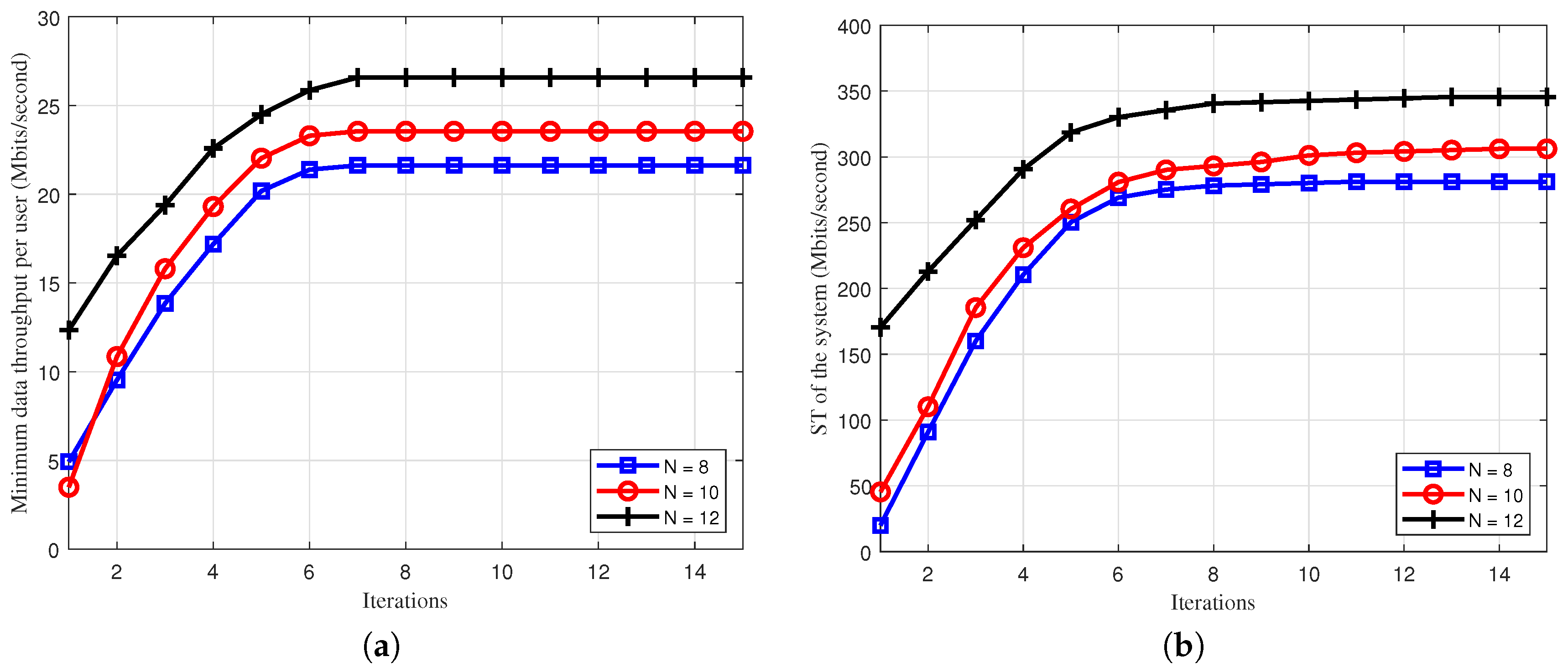
In Figure 3, we explore the convergent property of the proposed Algorithms 1 and 2. First, we can see that the minimum data throughput and sum throughput are monotonically increased when the number of iterations increases, which is aligned with the IA principles. Second, Algorithms 1 and 2 take about seven and twelve iterations to converge to the optimal solutions, respectively. The convergence patterns are quite independent with the problem size (i.e., the number of BS’s antennas N). The reason for this is that the convex problems (20) and (29) do not involve with N, whrich further confirms the low complexity of the proposed algorithm. Of course, increasing the number of BS’s antennas will improve the minimum data throughput per user, since more degrees-of-freedom are added to the system in order to support multiple users, thus mitigating the loss that is caused by ZF conditions.
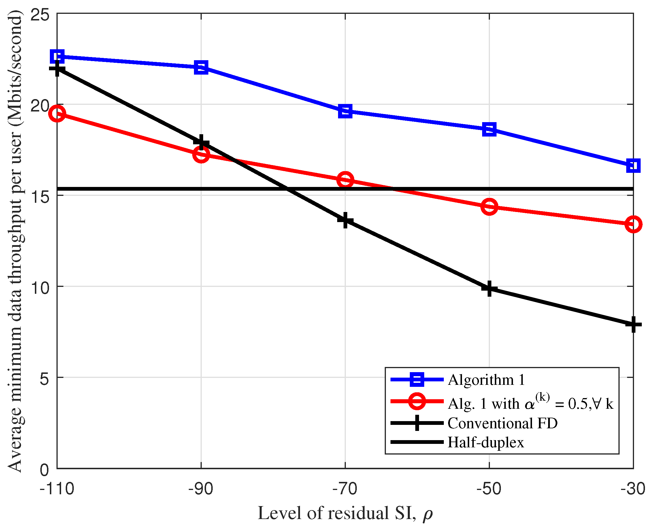
We show the effect of the level residual SI on the average minimum data throughput, ρ [ 110 , 30 ] dB, as in Figure 4. As can be seen, the performance of all FD schemes is degraded when ρ increases. It is clear that the higher the level residual SI, the stronger the SI power that is caused at BS. Unsurprisingly, the performance of half-duplex scheme is independent with ρ , since downlink and uplink are operated at two separate time blocks and, thus, there is no SI at BS. Notably, Algorithm 1 provides the best performance among all of the considered schemes in all range of ρ . The minimum data throughput of Algorithm 1 is mostly unchanged in typical range of ρ [ 110 , 90 ] dB and is slightly degraded when ρ > 90 dB. These observations further confirm the effectiveness of the proposed algorithm with user grouping and jointly optimizing all of the variables (including bandwidth) in order to more effectively manage the whole network interference. We can also see that the performance gap between Algorithm 1 and conventional FD is even deeper when ρ increases, which is attributed to the fact that the proposed user grouping is more beneficial in the case of severe SI.
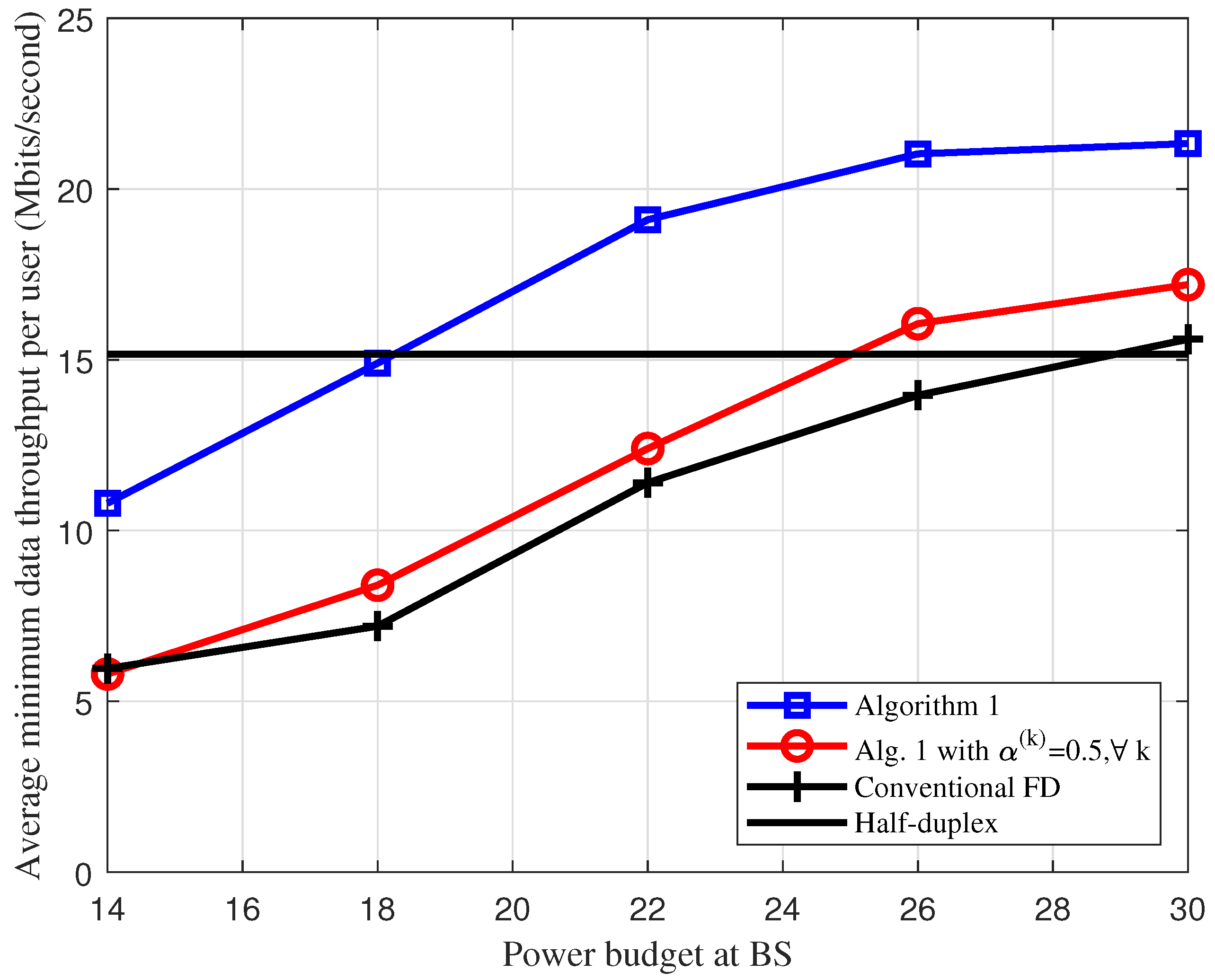
In Figure 5, we plot the average data throughput versus the transmit power at BS, P b s max [ 14 , 30 ] dBm. The performance of half-duplex is unchanged, since users in uplink mainly determine the minimum data throughput. We can see that the performance of FD-based schemes is significantly improved when P b s max from 14 dBm to 26 dBm, and then sightly increased when P b s max is large. This is because BS with higher power budget P b s max causes stronger SI to the reception of upink users. In order to maintain the max-min data throughput among all users, BS has to scale down its transmit power to reduce the SI power. Again, Algorithm 1 still offers the best performance among all FD schemes and haft-duplex scheme in the practical value of P b s max = 26 dBm.
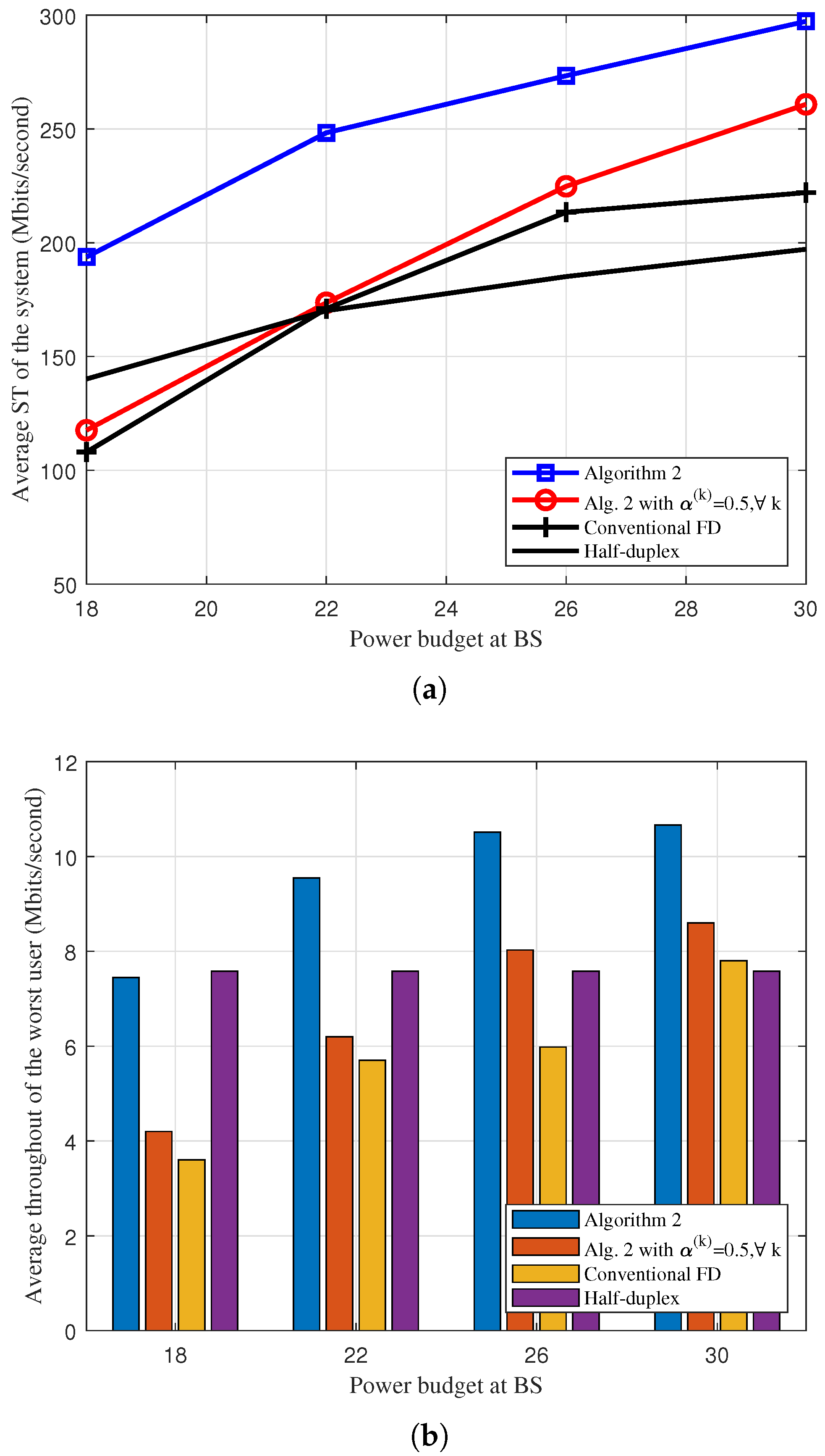
Finally, in Figure 6a, we depict the average ST versus the maximum transmit power of BS, P b s max [ 18 , 30 ] dBm, for the four resource allocation schemes. We can observe that the performance of the proposed user grouping-based schemes (i.e., Algorithm 2 and Algorithm 2 with α ( k ) = 0.5 , k ) increases quickly when P b s max increases. In addition, the average ST of the conventional FD tends to be saturated when P b s max > 26 dBm. The reason is that the higher the BS’s transmit power the stronger the SI power will cause to the uplink reception and, thus, a very high value of P b s max does not help to improve the sum throughput of the conventional FD scheme without user grouping. Next, in Figure 6b, we show the average throughput of the worst user given the ST in Figure 6a. In all cases, we can see that the proposed Algorithm 2 naturally offers the best performance in terms of user fairness. The low throughput of the worst user in other FD-based schemes is due the fact that BS will allocate a major portion of power budget to the users with good channel conditions in order to maximize the ST whenever the predetermined throughput threshold is satisfied.

6. Conclusions

In this paper, we considered the max-min throughput fairness and sum throughput optimization for IBFD IoT networks. We proposed a simple yet efficient user grouping method, aiming for an efficient network interference management. An ZF-based design was adopted in both downlink and uplink in order to reduce the computational complexity of the problem design. The formulated problems have a highly non-concave objective function that is subject to nonconvex constraints. Towards low-complexity solutions, we first converted the original problems to equivalent nonconvex problems, but with more tractable forms. We then developed low-complexity iterative algorithms that are based on the IA framework that converge to at least a local optimum. Numerical results were provided in order to demonstrate the significant performance improvement of the proposed method when compared to existing ones.

Author Contributions

Conceptualization, N.T.V.K. and V.D.N.; methodology, N.T.V.K. and V.D.N.; simulation, N.T.V.K. and V.D.N.; validation, N.T.V.K. and V.D.N.; writing—original draft preparation, N.T.V.K.; writing—review and editing, N.T.V.K. and V.D.N.; supervision, V.D.N.; project administration, V.D.N.; funding acquisition, V.D.N. Both authors have read and agreed to the published version of the manuscript.

Funding

This research received no external funding.

Conflicts of Interest

The authors declare no conflict of interest.

Abbreviations

The following abbreviations are used in this manuscript:
IBFDIn-band full-duplex
HDHalf-duplex
IAInner approximation
BSBase station
SISelf-interference
CCICo-channel interference
CSIChannel state information
5GFifth-generation wireless network
IoTInternet of Things
SEMSpectral efficiency maximization
STSum throughput
DoFDegrees-of-freedom
ZFZero-forcing
NOMANon-orthogonal multiple access
DLDownlink
ULUplink

Appendix A. Proof of Lemma 1

We first consider the function ln ( 1 + 1 / x ) / y , which is convex in the domain x , y R + . The first order Taylor approximation of ln ( 1 + 1 / x ) / y is given as:
ln 1 + 1 x y ln 1 + 1 x ¯ y ¯ x ln 1 + 1 x y ¯ | x ¯ ( x x ¯ ) ,     y ln 1 + 1 x ¯ y | y ¯ ( y y ¯ )
  = 2 ln 1 + 1 x ¯ y ¯ + 1 y ¯ ( x ¯ + 1 )     1 y ¯ x ¯ ( x ¯ + 1 ) x ln 1 + 1 x ¯ y ¯ 2 y .
The results in (16) are obtained by setting: x 1 = γ i dl , ( k ) , x 1 = γ j ul , ( k ) and y 1 = α ( k ) .

References

  1. Cisco Annual Internet Report (2018–2023) White Paper. 2020. Available online: https://www.cisco.com/c/en/us/solutions/collateral/executive--perspectives/annual--internet--report/white--paper--c11--741490.html (accessed on 9 March 2020).
  2. Ma, Z.; Xiao, M.; Xiao, Y.; Pang, Z.; Poor, H.V.; Vucetic, B. High-Reliability and Low-Latency Wireless Communication for Internet of Things: Challenges, Fundamentals, and Enabling Technologies. IEEE Internet Things J. 2019, 6, 7946–7970. [Google Scholar] [CrossRef]
  3. Ghahramani, M.; Qiao, Y.; Zhou, M.C.; O’Hagan, A.; Sweeney, J. AI-based modeling and data-driven evaluation for smart manufacturing processes. IEEE/CAA J. Autom. Sin. 2020, 7, 1026–1037. [Google Scholar] [CrossRef]
  4. Ericsson Mobility Report; Ericsson AB: Stockholm, Sweden, 2018. Available online: https://goo.gl/bSxgss (accessed on 16 November 2018).
  5. Andrews, J.; Buzzi, S.; Choi, W.; Hanly, S.; Lozano, A.; Soong, A.; Zhang, J. What Will 5G Be? IEEE J. Select. Area Commun. 2014, 32, 1065–1082. [Google Scholar] [CrossRef]
  6. Zhang, Z.; Long, K.; Vasilakos, A.V.; Hanzo, L. Full-Duplex Wireless Communications: Challenges, Solutions, and Future Research Directions. Proc. IEEE 2016, 104, 1369–1409. [Google Scholar] [CrossRef] [Green Version]
  7. Bazzi, A.; Masini, B.M.; Zanella, A. Performance Analysis of V2V Beaconing Using LTE in Direct Mode With Full Duplex Radios. IEEE Wirel. Commun. Lett. 2015, 4, 685–688. [Google Scholar] [CrossRef]
  8. Mahmood, N.H.; Sarret, M.G.; Berardinelli, G.; Mogensen, P. Full duplex communications in 5G small cells. In Proceedings of the 2017 13th International Wireless Communications and Mobile Computing Conference (IWCMC), Valencia, Spain, 26–30 June 2017; pp. 1665–1670. [Google Scholar] [CrossRef] [Green Version]
  9. Zhang, Z.; Chai, X.; Long, K.; Vasilakos, A.V.; Hanzo, L. Full duplex techniques for 5G networks: Self-interference cancellation, protocol design, and relay selection. IEEE Commun. Mag. 2015, 53, 128–137. [Google Scholar] [CrossRef] [Green Version]
  10. Bharadia, D.; McMilin, E.; Katti, S. Full duplex radios. Proc. ACM SIGCOMM Comput. Commun. Rev. 2013, 43, 375–386. [Google Scholar] [CrossRef]
  11. Riihonen, T.; Werner, S.; Wichman, R. Mitigation of loopback self-interference in full-duplex MIMO relays. IEEE Trans. Signal Process. 2011, 59, 5983–5993. [Google Scholar] [CrossRef]
  12. System Scenarios and Technical Requirements for Full-Duplex Concept. DUPLO Project, Deliverable D1.1. Available online: https://cordis.europa.eu/docs/projects/cnect/9/316369/080/deliverables/001-D11v10.pdf (accessed on 16 November 2018).
  13. Duarte, M.; Dick, C.; Sabharwal, A. Experiment-driven characterization of full-duplex wireless systems. IEEE Trans. Wirel. Commun. 2012, 11, 4296–4307. [Google Scholar] [CrossRef] [Green Version]
  14. Sabharwal, A.; Schniter, P.; Guo, D.; Bliss, D.W.; Rangarajan, S.; Wichman, R. In-band full-duplex wireless: Challenges and opportunities. IEEE J. Select. Areas Commun. 2014, 32, 1637–1652. [Google Scholar] [CrossRef] [Green Version]
  15. Nguyen, D.; Tran, L.N.; Pirinen, P.; Latva-aho, M. On the spectral efficiency of full-duplex small cell wireless systems. IEEE Trans. Wirel. Commun. 2014, 13, 4896–4910. [Google Scholar] [CrossRef]
  16. Huberman, S.; Le-Ngoc, T. MIMO Full-Duplex Precoding: A Joint Beamforming and Self-Interference Cancellation Structure. IEEE Trans. Wirel. Commun. 2015, 14, 2205–2217. [Google Scholar] [CrossRef]
  17. Nguyen, V.D.; Nguyen, H.V.; Nguyen, C.T.; Shin, O.S. Spectral Efficiency of Full-Duplex Multi-user System: Beamforming Design, User Grouping, and Time Allocation. IEEE Access 2017, 5, 5785–5797. [Google Scholar] [CrossRef]
  18. Tam, H.H.M.; Tuan, H.D.; Ngo, D.T. Successive Convex Quadratic Programming for Quality-of-Service Management in Full-Duplex MU-MIMO Multicell Networks. IEEE Trans. Commun. 2016, 64, 2340–2353. [Google Scholar] [CrossRef]
  19. Nguyen, H.V.; Nguyen, V.D.; Dobre, O.A.; Wu, Y.; Shin, O.S. Joint antenna array mode selection and user assignment for full-duplex MU-MISO systems. IEEE Trans. Wirel. Commun. 2019, 18, 2946–2963. [Google Scholar] [CrossRef]
  20. Chalise, B.K.; Suraweera, H.A.; Zheng, G.; Karagiannidis, G.K. Beamforming Optimization for Full-Duplex Wireless-Powered MIMO Systems. IEEE Trans. Commun. 2017, 65, 3750–3764. [Google Scholar] [CrossRef] [Green Version]
  21. Nguyen, V.D.; Duong, T.Q.; Tuan, H.D.; Shin, O.S.; Poor, H.V. Spectral and Energy Efficiencies in Full-Duplex Wireless Information and Power Transfer. IEEE Trans. Commun. 2017, 65, 2220–2233. [Google Scholar] [CrossRef] [Green Version]
  22. Aquilina, P.; Cirik, A.C.; Ratnarajah, T. Weighted Sum Rate Maximization in Full-Duplex Multi-User Multi-Cell MIMO Networks. IEEE Trans. Commun. 2017, 65, 1590–1608. [Google Scholar] [CrossRef] [Green Version]
  23. Nguyen, H.V.; Nguyen, V.D.; Dobre, O.A.; Nguyen, D.N.; Dutkiewicz, E.; Shin, O.S. Joint Power Control and User Association for NOMA-Based Full-Duplex Systems. IEEE Trans. Commun. 2019, 67, 8037–8055. [Google Scholar] [CrossRef] [Green Version]
  24. Nguyen, V.D.; Nguyen, H.V.; Dobre, O.A.; Shin, O.S. A New Design Paradigm for Secure Full-Duplex Multiuser Systems. IEEE J. Select. Areas Commun. 2018, 36, 1480–1498. [Google Scholar] [CrossRef]
  25. Zabini, F.; Bazzi, A.; Masini, B.M.; Verdone, R. Optimal Performance Versus Fairness Tradeoff for Resource Allocation in Wireless Systems. IEEE Trans. Wirel. Commun. 2017, 16, 2587–2600. [Google Scholar] [CrossRef]
  26. Marks, B.R.; Wright, G.P. A general inner approximation algorithm for nonconvex mathematical programs. Oper. Res. 1978, 26, 681–683. [Google Scholar] [CrossRef]
  27. Beck, A.; Ben-Tal, A.; Tetruashvili, L. A sequential parametric convex approximation method with applications to nonconvex truss topology design problems. J. Glob. Optim. 2010, 47, 29–51. [Google Scholar] [CrossRef]
  28. Peaucelle, D.; Henrion, D.; Labit, Y. Users Guide for SeDuMi Interface 1.03; LAAS-CNRS: Toulouse, France, 2002. [Google Scholar]
  29. I. MOSEK ApS. 2014. Available online: http://www.mosek.com (accessed on 16 November 2018).
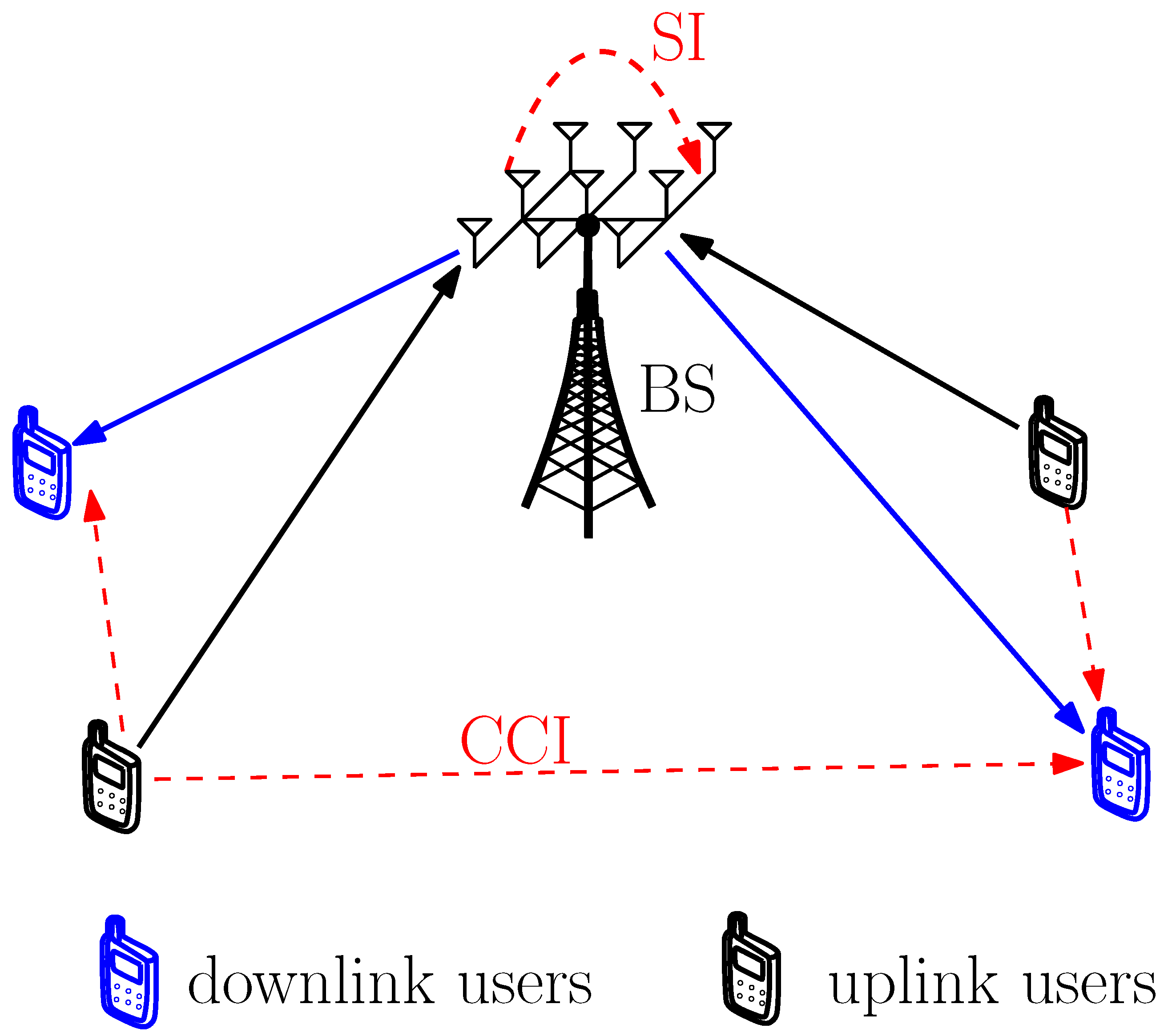
Figure 1. Illustration of in-band full-duplex (IBFD)-based systems wih multiple HD downlink users and uplink users.
Electronics 09 02182 g001
Figure 2. IBFD operation: base station (BS) simultaneously serves sets of strong downlink users in D 1 and weak uplink users in U 1 using a portion of system bandwidth α ( 1 ) B , and sets of weak downlink users in D 2 and strong uplink users in U 2 using the remaining portion of system bandwidth α ( 2 ) B .
Electronics 09 02182 g002
Figure 3. Convergence behavior of Algorithms 1 and 2 with the difference number of antennas at BS. (a) Algorithm 1. &(b) Algorithm 2.
Electronics 09 02182 g003
Figure 4. Effect of the level residual self-interference (SI) on the average minimum data throughput, ρ [dB].
Electronics 09 02182 g004
Figure 5. Average minimum data throughput versus the transmit power at BS, P b s max [dBm].
Electronics 09 02182 g005
Figure 6. Average performance of Algorithm 2 versus the transmit power at BS, P b s max [dBm]. (a) Average sum throughput (ST) of the system versus P b s max . (b) Average throughput of the worst user versus P b s max , given the average ST in Figure 6a.
Electronics 09 02182 g006
Table 1. Simulation Parameters.
Simulation ParameterValue
System bandwidth10 MHz
Noise power spectral density at BS and uplink users N 0 = −174 dBm/Hz
Path loss between BS and users103.8 + 20.9 log 10 ( d ) dB
Path loss between a uplink user and a downlink user145.4 + 37.5 log 10 ( d ) dB
Power budget at BS P b s max = 26 dBm
Power budget at uplink users P j ( k ) , max =23 dBm, j , k
Level of residual SI, ρ −75 dB
Number of antennas at BS N = 8
Number of downlink users D = 6
Number of uplink users U = 6
Predetermined throughput threshold r ¯ r ¯ i dl , ( k ) = r ¯ j ul , ( k ) = 1 bits/s ,   i , j , k
Publisher’s Note: MDPI stays neutral with regard to jurisdictional claims in published maps and institutional affiliations.