Abstract
There is a growing interest in chipless radio-frequency identification (RFID) technology for a number of Internet of things (IoT) applications. This is due to its advantages of being of low-cost, low-power, and fully printable. In addition, it enjoys ease of implementation. In this paper, we present a novel, compact, chipless radio-frequency identification (RFID) tag that can be read with either vertical or horizontal polarization within its frequency bandwidth. This increases the sturdiness and detection ability of the RFID system. In addition, the difference between the vertical and horizontal responses can be used for tag identification. The proposed tag uses strip length variations to double the coding capacity and thereby reduce the overall size by almost 50%. It has a coding capacity of 20 bits in the operating bandwidth 3 GHz–7.5 GHz, and its spatial density is approximately 11 bits/cm2. The proposed tag has a 4.44 bits/GHz spectral capacity, 2.44 bits/cm2/GHz encoding capacity, a spatial density at the center frequency of 358.33 bits/λ2, and an encoding capacity at the center frequency of 79.63 bits/λ2/GHz. A prototype is fabricated and experimentally tested at a distance of 10 cm from the RFID reader system. Then, we compare the measured results with the simulations. The simulated results are in reasonable agreement with the simulated ones.
1. Introduction
The Internet of things (IoT) allows objects and people to be connected at any place and time through the Internet. However, this technology needs some important components to enable communication among these objects. Radio-frequency identification (RFID) is a wireless technique that can be used for sensing, identification, and tracking. Therefore, RFID tags and sensors have great potential for use in IoT applications such as smart cites and industrial and tracking systems [1,2,3,4]. The RFID system utilizes electromagnetic (EM) waves instead of the optical waves which are used with quick response (QR) codes and barcodes. Furthermore, many materials are penetrated by the EM waves, and thus the RFID tags could be read even when they are isolated by other low-loss materials [5,6]. Conventional RFID tags utilize integrated circuit (IC) chips that limit their applicability due to their prohibitive costs. Chipless RFID tags have been recently proposed to reduce the cost of the tags by removing the expensive IC chips, thus producing fully printable tags [7,8]. Chipless RFID tags generally consist of the following: (1) the chipless RFID tag, which contains a multi-resonance structure for object identification, and (2) the RFID reader that is used to interrogate the tag and read the retransmitted or backscattered response from a tag [9,10,11,12].
In the literature, different approaches have been proposed for encoding RFID tags with data such as time [13,14], frequency [12,15,16,17], phase [18], image [19], and hybrid domains [20,21]. In frequency domain-based tags, the RFID reader uses radio signals to interrogate the tag, which then retransmits or backscatters the frequency signature back to the reader. These tags exist in either retransmission mode or backscattered mode varieties. Retransmission-based tags consist of multiple resonant structures and one or more ultra-wideband antennas for transmission and reception of the data [22,23,24]. On the other hand, in backscattering mode, no separate antennas are required [25,26,27].
To date, many different RFID structures have been demonstrated, including dual-polarized I-slots [10,11], U-shaped strips [9], L-shaped strips [28], square loops [29], triangular loops [30], circular loops [31], open loops [32], and inverted M-shapes [33]. High-impedance surface-based square loop resonators were proposed by Filippo Costa et al. [34]. The authors used a frequency selective surface (FSS) with an overall size of 4.5 cm2 × 4.5 cm2 and a coding capacity of 5 bits. Another work that used a quarter wavelength slot resonator was reported in [31] to encode 24 bits within the size of 2.4 cm2 × 2.4 cm2. In [35], a 16-bit dual polarized chipless RFID tag was presented. Two rectangular patches were placed in horizontal polarization, and two were placed in vertical polarization to double the number of bits within the same frequency bandwidth.
There are two types of frequency-selective surface-based chipless RFID system configurations: monostatic and bistatic systems. Bistatic systems use two applicators: one for interrogating and the other for reading the RF signal. In contrast, monostatic systems use only one applicator for both reading and interrogating. This type of system is generally considerably less expensive than a bistatic system as it requires only one antenna and a less-complex setup. Figure 1 shows the setup for the proposed tag intended for a monostatic RFID system.
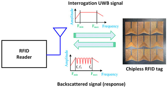
Figure 1.
Monostatic setup for the proposed chipless radio-frequency identification (RFID) tag.
The main obstacle in deploying RFID systems remains the high cost of the tags. The cost has to be extremely low to justify mass production. Therefore, the present study aims to develop low-cost, chipless RFID tags by (1) reducing the overall size and the bandwidth-per-bit of chipless RFID tags and (2) increasing the spectral capacity (bits/GHz), spatial density (bits/cm2), and spatial density at the center frequency (bits/λ2).
In this paper, we present a novel chipless RFID tag consisting of overturned M-shaped strips. This compact tag uses dual polarizations to make the reading procedure more robust and employs length variation encoding to double the coding capacity from 10 to 20 bits. We have simulated the proposed tag as an infinite structure, using a 3D full-wave electromagnetic (EM) simulator. The proposed tag has a 4.44 bits/GHz spectral capacity, 2.44 bits/cm2/GHz encoding capacity, a spatial density at the center frequency of 358.33 bits/λ2, and an encoding capacity at the center frequency of 79.63 bits/λ2/GHz. Note that processing multiple RFID tags may cause collision. In such cases, tag-to-tag anti-collision can be implemented by one of the earlier presented techniques in [36,37,38,39,40,41,42,43].
The remainder of this paper is structured as follows. In Section 2, the tag design methodology is presented. Section 3 involves the simulation results for some configurations. In Section 4, one configuration of the proposed tag is experimentally validated. Finally, some concluding remarks are presented in Section 5.
2. Tag Design
The geometry of the proposed tag is shown in Figure 2. It consisted of 10 inverted M-shaped strips implemented on a Rogers RT5880 substrate, with a thickness of 0.256 mm and a dielectric constant = 2.2. In Figure 2, w and l are the width and length of the proposed tag, respectively, sx is the horizontal separation between two vertical elements, which was fixed for all strip resonators, sy is the vertical separation between two slanted elements, which was different from one strip to another, and wr is the width of each strip. Each inverted M-shaped strip structure could be utilized in either an active or a passive mode of operation. The existence of a null in the frequency response denoted the active mode (logic 1), while the nonexistence of the null denoted the passive mode (logic 0).
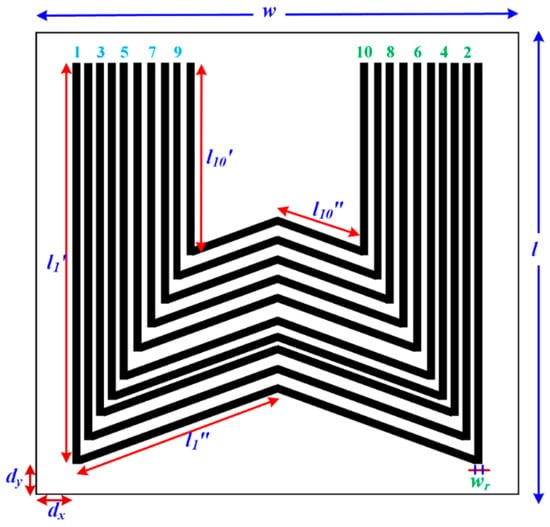
Figure 2.
Structure of the proposed M-strips tag.
Note that the proposed tag was different from the structure developed in [44]; it was based on the inverted M-shaped strips implemented on the dielectric substrate, while that of [44] was based on U-shaped slots etched in a metallic background.
Figure 3 shows 10 strips in both active and passive modes. The resonant frequency of each strip could be removed from the operating band by adding some open circuits (cuts) at different portions of the strip resonator or by removing the appropriate strip. In general, the 10 active resonators (Figure 3a) could be used to logically represent 1111111111, while the 10 passive resonators (Figure 3b) logically represent 0000000000.
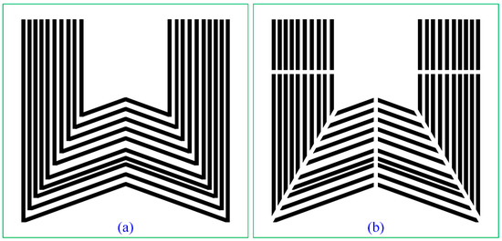
Figure 3.
Structure of the proposed M-strips tag in (a) active mode (ID: 1111111111) and (b) passive mode (ID: 0000000000).
We have optimized the proposed structure to obtain deep notches at suitable frequencies in the operating frequency band from 3 GHz to 7.5 GHz. Essentially, each single-strip resonator was designed to operate at one resonance frequency (one notch). Then, another strip resonator was added to obtain two notches in the operating frequency band. In this way, the number of resonance frequencies could be controlled by removing or adding resonators. Our structure utilized 10 optimized strips to obtain 10 resonance frequencies (notches). The fundamental and theoretical analysis of these types of tags were discussed by F. Costa et al. in [25,34] and by N. Karmakar et al. in [9,10,11,12,30,45]. The total length of each strip resonator was the sum of the lengths of the vertical and slanted elements:
Table 1 lists the total length of each strip resonator. The first strip, which was the longest, resonated at the lowest resonant frequency and corresponded to the most significant bit. On the other hand, the last strip, which had smallest length, gave the highest resonance frequency and corresponded to the least significant bit.

Table 1.
Physical lengths of the strip resonators.
We analyzed the proposed tag as an infinite structure using Floquet boundary conditions. When an exciting port sent an RF signal to the tag, a surface current was induced around each resonator at its resonant frequency. The proposed structure therefore exhibited frequency-selective performance, with deep notches at the desired resonant frequencies. Figure 4 shows the simulated response for all 10 strips (each shown separately).
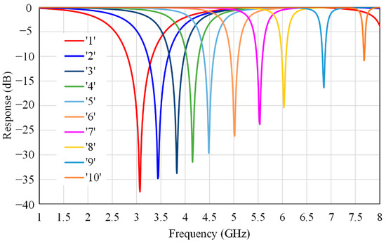
Figure 4.
Simulated response of the overturned M−shaped strips (one by one).
3. Simulation Results
We designed and simulated seven different passive tags with seven different codes to validate the concept. Figure 3a shows the first code, where all 10 strips were in active mode, which corresponded to the structure code 1111111111. Figure 3b shows the second code, where all strips were in passive mode, representing the code 0000000000. The other five bit codes we chose were 1010101010, 0101010101, 1010000000, 1010001111, and 0000011111. The simulation reflection coefficients (S11) for these different codes are shown in Figure 5, Figure 6, Figure 7 and Figure 8.
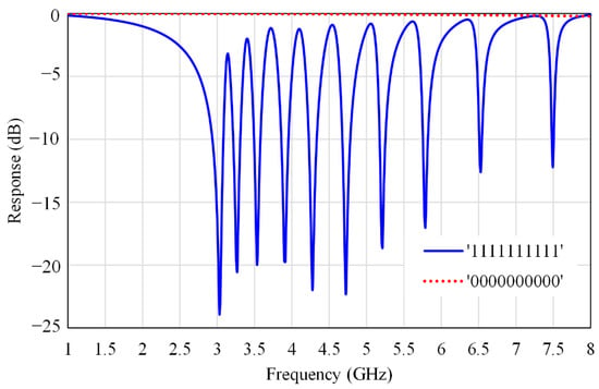
Figure 5.
Simulated response of the M−strips tag with two different codes: 1111111111 and 0000000000.
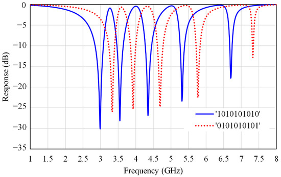
Figure 6.
Simulated response of the M−strips tag with two different codes: 1010101010 and 0101010101.
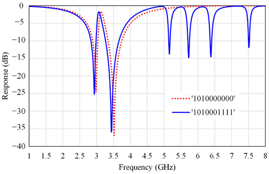
Figure 7.
Simulated response of the M−strips tag with two different codes: 1010000000 and 1010001111.
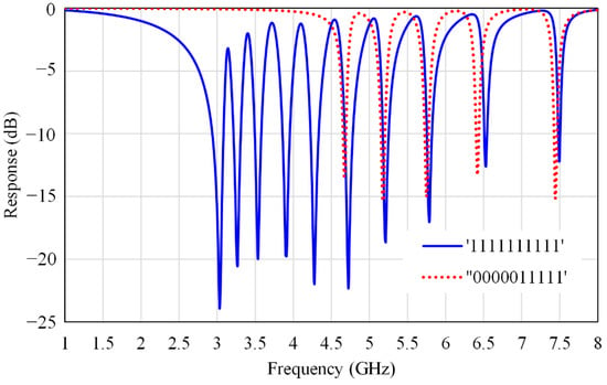
Figure 8.
Simulated response of the proposed M-strips tag with two different codes: 1111111111 and 0000011111.
The developed structure could be excited by either a horizontally or vertically polarized plane wave. For each polarization, the response waveform had 10 notches in the given operating bandwidth. Table 2 presents the frequency differences between the two responses obtained for excitation with vertical and horizontal polarizations. The maximum variance in dBs between the resonant frequencies for the two polarizations was around 140 MHz, while the minimum variance was almost 14 MHz. A shift in resonant frequencies between the two polarizations was necessary to achieve sufficiently sharp peaks for the two responses [25]. These sharp peaks could also be used for encoding data, because all the sharp peaks were present in the all-ones code. For this state, there were thus 10 sharp peaks, as shown in Figure 9. Figure 10 and Figure 11 show the frequency responses and the differences in dBs between the vertically and horizontally polarized S11 for the codes 1010001111 and 1010000000, respectively.

Table 2.
Possible frequencies for the all-ones code with vertical and horizontal polarizations.
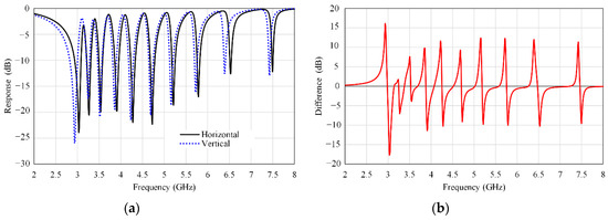
Figure 9.
Code: 1111111111. (a) Frequency responses under excitation with vertical and horizontal polarizations. (b) The amplitude difference in dBs between the two responses.
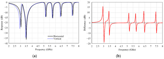
Figure 10.
Code: 1010001111. (a) Frequency responses under excitation with vertical and horizontal polarizations. (b) The amplitude difference in dBs between the two responses.
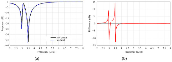
Figure 11.
Code: 1010000000. (a) Frequency responses under excitation with vertical and horizontal polarizations. (b) The amplitude difference in dBs between the two responses.
4. Strip Length Variation Method
The resonant frequency of each strip resonator was inversely proportional to its physical length. Consequently, increasing the strip resonator length decreased its resonant frequency, and vice versa. Hence, each M-strip was able to represent one of the four probable codes: 00, 01, 10, and 11. In the first code, 00, the strip resonator i worked in passive mode (with open circuits). No resonance frequency could be detected in the operating bandwidth. In the second code, 01, the length of strip i decreased by a small factor , and the resonance frequency became instead of . On the other hand, the third code, 10, was achieved when the length of strip i increased by a small factor . Therefore, the resonant frequency became instead of . The last code, 11, came with the original strip, which had a length and corresponded to the resonant frequency . These four codes for the single strip resonator are summarized in Table 3.

Table 3.
Possible states for a single overturned M-shaped resonator.
In this way, the number of bits per single strip resonator increased to two bits. Therefore, the coding capacity (number of bits per tag) and coding density (number of bits per centimeter square) could be doubled within the same frequency range. That means the coding capacity increased to 20 bits for the same size when the method of variation length was used. This saved 50% of the overall size.
For the all-ones configuration (ID: 1111111111), the simulated values of S11 for the last four cases listed in Table 3 are presented in Figure 12. Table 4 lists the corresponding frequencies for the M-strip tag with the original length and increased and decreased strip lengths. The optimized value of ΔL used in our structure was 0.33 mm. The tolerance value not affecting the tag performance was about 110 micrometers.
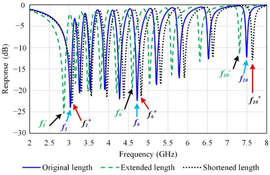
Figure 12.
Simulated values of the simulation reflection coefficients (S11) for the M-strips resonators with length variations.

Table 4.
Corresponding frequencies for the M-strip resonators with length variations.
5. Experimental Results
One of the designed tags was fabricated and experimentally tested to validate the idea. This prototype had the all-ones bit code (1111111111). Although the simulated reflection coefficients were the results for an infinite array of the proposed overturned M-strip tags, practically, we reduced the fabricated tag to a finite 3 × 3 array of unit cells to decrease the tag size and the fabrication cost. Figure 12 shows the fabricated code with a 3 × 3 array of unit cells.
We measured the response of the fabricated tag shown in Figure 12 using the measurement setup described in Figure 13. We measured its frequency response using a two-port power network analyzer PNA-X(N5242A) and a wideband horn antenna operating from 1 GHz to 18 GHz. The tag was placed at a distance of 10 cm from the RFID reader system. The measured and simulated results for the all-ones code are compared in Figure 14. The measured results were in suitable agreement with the simulation, although there were slight shifts at some frequencies due to manufacture and testing mistakes.
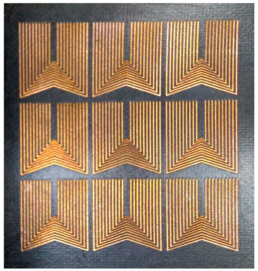
Figure 13.
The fabricated code (ID: 1111111111).
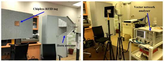
Figure 14.
Monostatic measurement setup.
It is observed from Figure 15 that there were ten frequency nulls in the backscattered signal from the fabricated tag. These ten resonance frequencies could be used to encode ten bits within the frequency band of 3 GHz–7.5 GHz.
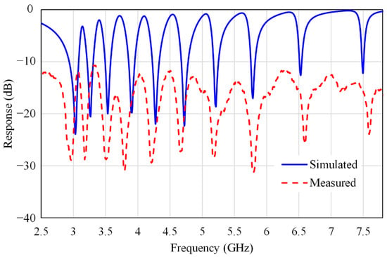
Figure 15.
Simulated and measured values of S11 for the all-ones code at a 10 cm distance from the RFID reader.
The backscattered chipless RFID tags can be implemented in two forms: the strip-based structure proposed in this paper and the slot-based form, as given in [33]. Within the same frequency band and capacity, the proposed structure needs less copper material in its implantation; therefore, it is cheaper when compared with the slot-based structure. However, the proposed structure needs more optimization effort in order to reduce the mutual effect of adjacent lines, compared with the slot-based structure. Moreover, the distance between the tag and reader for accurate detection (60 cm) of the slot-base structure is greater than the distance between the tag and the reader of the proposed structure (10 cm). Although the proposed structure is lower in cost, these drawbacks may limit the applications of the proposed structure.
Table 5 compares the performance of the proposed tag with those of some existing chipless RFID backscatter-based tags. The performance of a chipless RFID tag is defined not only by its encoding capacity (bits/cm2 /GHz), but also by other metrics. These new metrics, defined in [23,46,47], include the spectral-capacity (bits/GHz), spatial density (bits/cm2), spatial density at the center frequency (bits/λ2), and the encoding capacity at the center frequency (bits/λ2/GHz).

Table 5.
Comparison between the proposed tag and different backscatter-based chipless RFID tags.
In this table, the proposed tag exhibits high performance at the center frequency in terms of spatial density and encoding capacity. The proposed tag can be used to encode 11 bits/cm2, and it has a spectral capacity of 4.44 bits/GHz, a spatial density at the center frequency of 358.33 bits/λ2, an encoding capacity of 2.44 bits/cm2/GHz, and an encoding capacity at the center frequency of 79.63 bits/λ2/GHz. Other performance parameters of this device are listed in the last line of Table 5.
6. Conclusions
We have presented a novel and compact tag consisting of overturned M-shaped strips in this paper. We showed that the coding capacity of such a device could be doubled within the same frequency range of 3 GHz–7.5 GHz for a given tag size. We fabricated an all-ones tag and tested it at a distance of 10 cm from the RFID reader, and we compared the measured results with a simulation. The proposed tag can be used to encode 11 bits/cm2, and it has a spectral capacity of 4.44 bits/GHz, a spatial density at the center frequency of 358.33 bits/λ2, an encoding capacity of 2.44 bits/cm2/GHz, and an encoding capacity at the center frequency of 79.63 bits/λ2/GHz.
Author Contributions
Conceptualization, K.I. and W.M.A.; software, W.M.A. and K.I.; methodology, W.M.A., A.-F.A.S., K.I. and S.A.A.; formal analysis, W.M.A. and A.-F.A.S.; validation, K.I. and W.M.A.; investigation, A.-F.A.S. and S.A A.; resources, S.A.A. and A.-F.A.S.; data curation, W.M.A. and K.I.; writing (original draft preparation), W.M.A.; writing (review and editing), W.M.A., A.-F.A.S., S.A.A. and K.I.; visualization, W.M.A. and K.I.; supervision, S.A.A. and A.-F.A.S. All authors have read and agreed to the published version of the manuscript.
Funding
This work was supported by the Researchers Supporting Project number (RSP-2020/46), King Saud University, Riyadh, Saudi Arabia.
Acknowledgments
The authors would like to acknowledge the Researchers Supporting Project at King Saud University.
Conflicts of Interest
The authors declare no conflict of interest.
References
- Mulloni, V.; Donelli, M. Chipless RFID Sensors for the Internet of Things: Challenges and Opportunities. Sensors 2020, 20, 2135. [Google Scholar] [CrossRef] [PubMed]
- Landaluce, H.; Arjona, L.; Perallos, A.; Falcone, F.; Angulo, I.; Muralter, F. A Review of IoT Sensing Applications and Challenges Using RFID and Wireless Sensor Networks. Sensors 2020, 20, 2495. [Google Scholar] [CrossRef] [PubMed]
- Babaeian, F.; Karmakar, N.C. Time and Frequency Domains Analysis of Chipless RFID Back-Scattered Tag Reflection. IoT 2020, 1, 7. [Google Scholar] [CrossRef]
- Kim, S. Inkjet-Printed Electronics on Paper for RF Identification (RFID) and Sensing. Electronics 2020, 9, 1636. [Google Scholar] [CrossRef]
- Forouzandeh, M.; Karmakar, N.C. Chipless RFID tags and sensors: A review on time-domain techniques. Wirel. Power Transf. 2015, 2, 62–77. [Google Scholar] [CrossRef]
- Xiao, Y.; Yu, S.; Wu, K.; Ni, Q.; Janecek, C.; Nordstad, J. Radio frequency identification: Technologies, applications, and research issues. Wirel. Commun. Mob. Comput. 2007, 7, 457–472. [Google Scholar] [CrossRef]
- Preradovic, S. Chipless RFID System for Barcode Replacement. Ph.D. Thesis, Department of Electrical and Computer Systems Engineering, Monash University, Melbourne, Australia, 2009. [Google Scholar]
- Herrojo, C.; Paredes, F.; Mata-Contreras, J.; Martín, F. Chipless-RFID: A Review and Recent Developments. Sensors 2019, 19, 3385. [Google Scholar] [CrossRef]
- Islam, M.A.; Karmakar, N.C. A novel compact printable dual-polarized chipless RFID system. IEEE Trans. Microw. Theory Tech. 2012, 60, 2142–2151. [Google Scholar] [CrossRef]
- Islam, M.A.; Karmakar, N.C. A 4 × 4 Dual Polarized mm-Wave ACMPA Array for a Universal mm-Wave Chipless RFID Tag Reader. IEEE Trans. Antennas Propag. 2015, 63, 1633–1640. [Google Scholar] [CrossRef]
- Islam, M.A.; Karmakar, N.C. Compact printable chipless RFID systems. IEEE Trans. Microw. Theory Tech. 2015, 63, 3785–3793. [Google Scholar] [CrossRef]
- Islam, M.A.; Karmakar, N.C. Real-World Implementation Challenges of a Novel Dual-Polarized Compact Printable Chipless RFID Tag. IEEE Trans. Microw. Theory Tech. 2015, 63, 4581–4591. [Google Scholar] [CrossRef]
- Pöpperl, M.; Parr, A.; Mandel, C.; Jakoby, R.; Vossiek, M. Potential and practical limits of time-domain reflectometry chipless RFID. IEEE Trans. Microw. Theory Tech. 2016, 64, 2968–2976. [Google Scholar] [CrossRef]
- Herrojo, C.; Mata-Contreras, J.; Paredes, F.; Núñez, A.; Ramon, E.; Martín, F. Near-Field Chipless-RFID System With Erasable/Programmable 40-bit Tags Inkjet Printed on Paper Substrates. IEEE Microw. Wirel. Compon. Lett. 2018, 28, 272–274. [Google Scholar] [CrossRef]
- Islam, M.A.; Karmakar, N. A Compact Printable Dual-Polarized Chipless RFID Tag Using Slot Length Variation in ‘I’ Slot Resonators. In Proceedings of the European Microwave Conference (EuMC), Paris, France, 6–11 September 2015; pp. 96–99. [Google Scholar]
- Adbulkawi, W.M.; Sheta, A.A. A Compact Chipless RFID Tag Based on Frequency Signature. In Proceedings of the 2017 9th IEEE-GCC Conference and Exhibition (GCCCE), Manama, Bahrain, 8–11 May 2017; pp. 1–4. [Google Scholar]
- Adbulkawi, W.M.; Sheta, A.A. Printable Chipless RFID Tags for IoT Applications. In Proceedings of the 2018 1st International Conference on Computer Applications & Information Security (ICCAIS), Riyadh, Saudi Arabia, 4–6 April 2018; pp. 1–4. [Google Scholar]
- Balbin, I.; Karmakar, N.C. Phase-Encoded Chipless RFID Transponder for Large-Scale Low-Cost Applications. IEEE Microw. Wirel. Compon. Lett. 2009, 19, 509–511. [Google Scholar] [CrossRef]
- Nguyen, D.H.; Zomorrodi, M.; Karmakar, N.C. Spatial-Based Chipless RFID System. IEEE J. Radio Freq. Identif. 2019, 3, 46–55. [Google Scholar] [CrossRef]
- Babaeian, F.; Karmakar, N.C. Hybrid Chipless RFID Tags- A Pathway to EPC Global Standard. IEEE Access 2018, 6, 67415–67426. [Google Scholar] [CrossRef]
- Vena, A.; Perret, E.; Tedjini, S. Chipless RFID tag using hybrid coding technique. IEEE Trans. Microw. Theory Tech. 2011, 59, 3356. [Google Scholar] [CrossRef]
- Abdulkawi, W.M.; Sheta, A.A. High coding capacity chipless radiofrequency identification tags. Microw. Opt. Technol. Lett. 2020, 62, 592–599. [Google Scholar] [CrossRef]
- Abdulkawi, W.M.; Sheta, A.-F.A. K-State Resonators for High-Coding-Capacity Chipless RFID Applications. IEEE Access 2019, 7, 185868–185878. [Google Scholar] [CrossRef]
- Abdulkawi, W.M.; Sheta, A.-F.A. Four-state coupled-line resonator for chipless RFID tags application. Electronics 2019, 8, 581. [Google Scholar] [CrossRef]
- Costa, F.; Genovesi, S.; Monorchio, A. Normalization-Free Chipless RFIDs by Using Dual-Polarized Interrogation. IEEE Trans. Microw. Theory Tech. 2016, 64, 310–318. [Google Scholar] [CrossRef]
- Marindra, A.M.J.; Tian, G.Y. Chipless RFID Sensor Tag for Metal Crack Detection and Characterization. IEEE Trans. Microw. Theory Tech. 2018, 66, 2452–2462. [Google Scholar] [CrossRef]
- Bibile, M.A.; Karmakar, N.C. Moving Chipless RFID Tag Detection Using Adaptive Wavelet-Based Detection Algorithm. IEEE Trans. Antennas Propag. 2018, 66, 2752–2760. [Google Scholar] [CrossRef]
- Issa, K.; Ashraf, M.A.; AlShareef, M.R.; Behairy, H.; Alshebeili, S.; Fathallah, H. A Novel L-Shape Ultra Wideband Chipless Radio-Frequency Identification Tag. Int. J. Antennas Propag. 2017, 2017. [Google Scholar] [CrossRef]
- Huang, H.-f.; Su, L. A compact dual-polarized chipless RFID tag by using nested concentric square loops. IEEE Antennas Wirel. Propag. Lett. 2017, 16, 1036–1039. [Google Scholar] [CrossRef]
- Islam, M.A.; Yap, Y.; Karmakar, N. ‘Δ’ Slotted Compact Printable Orientation Insensitive Chipless RFID Tag for Long Range Applications. In Proceedings of the 9th International Conference on Electrical and Computer Engineering (ICECE), Dhaka, Bangladesh, 20–22 December 2016; pp. 283–286. [Google Scholar]
- Rezaiesarlak, R.; Manteghi, M. Complex-natural-resonance-based design of chipless RFID tag for high-density data. IEEE Trans. Antennas Propag. 2014, 62, 898–904. [Google Scholar] [CrossRef]
- Wang, L.; Liu, T.; Sidén, J.; Wang, G. Design of chipless RFID tag by using miniaturized open-loop resonators. IEEE Trans. Antennas Propag. 2018, 66, 618–626. [Google Scholar] [CrossRef]
- Abdulkawi, W.M.; Sheta, A.-F.A.; Issa, K.; Alshebeili, S.A. Compact Printable Inverted-M Shaped Chipless RFID Tag Using Dual-Polarized Excitation. Electronics 2019, 8, 580. [Google Scholar] [CrossRef]
- Costa, F.; Genovesi, S.; Monorchio, A. A chipless RFID based on multiresonant high-impedance surfaces. IEEE Trans. Microw. Theory Tech. 2013, 61, 146–153. [Google Scholar] [CrossRef]
- Islam, M.A.; Karmakar, N. Design of a 16-bit Ultra-Low Cost Fully Printable Slot-Loaded Dual-Polarized Chipless RFID Tag. In Proceedings of the Asia-Pacific Microwave Conference, Melbourne, Victoria, Australia, 5–8 December 2011; pp. 1482–1485. [Google Scholar]
- Azim, R.-E.; Karmakar, N. A Collision Avoidance Methodology for Chipless RFID Tags. In Proceedings of the Asia-Pacific Microwave Conference, Melbourne, Victoria, Australia, 5–8 December 2011; pp. 1514–1517. [Google Scholar]
- Rezaiesarlak, R.; Manteghi, M. A space–time–frequency anticollision algorithm for identifying chipless RFID tags. IEEE Trans. Antennas Propag. 2013, 62, 1425–1432. [Google Scholar] [CrossRef]
- Rezaiesarlak, R.; Manteghi, M. A New Anti-Collision Algorithm for Identifying Chipless Rfid Tags. In Proceedings of the 2013 IEEE Antennas and Propagation Society International Symposium (APSURSI), Orlando, FL, USA, 7–13 July 2013; pp. 1722–1723. [Google Scholar]
- Rezaiesarlak, R.; Manteghi, M. On the application of short-time matrix pencil method for wideband scattering from resonant structures. IEEE Trans. Antennas Propag. 2014, 63, 328–335. [Google Scholar] [CrossRef]
- Karmakar, N.C. Anti-Collision Methods for Chipless RFID Systems. In Proceedings of the 2015 Asia-Pacific Microwave Conference (APMC), Nanjing, China, 6–9 December 2015; pp. 1–3. [Google Scholar]
- Barahona, M.; Betancourt, D.; Ellinger, F. Using UWB IR Radar Technology to Decode Multiple Chipless RFID Tags. In Proceedings of the 2016 IEEE International Conference on Ubiquitous Wireless Broadband (ICUWB), Nanjing, China, 16–19 October 2016; pp. 1–6. [Google Scholar]
- El-Awamry, A.; Khaliel, M.; Fawky, A.; Kaiser, T. A Novel Multi-Tag Identification Technique for Frequency Coded Chipless RFID Systems Based on Look-up-Table Approach. In Proceedings of the 2017 11th European Conference on Antennas and Propagation (EUCAP), Paris, France, 19–24 March 2017; pp. 2070–2074. [Google Scholar]
- Li, Z.; Lan, Y.; He, G.; He, S.; Wang, S. Chipless RFID Tag Anti-Collision Algorithm Based on Successive Approximation Comparative Amplitude Coding. In Proceedings of the 2018 Chinese Automation Congress (CAC), Xi’an, China, 30 November–2 December 2018; pp. 2396–2401. [Google Scholar]
- Karmakar, N.C.; Amin, E.M.; Saha, J.K. Chipless RFID Sensors; John Wiley & Sons: Hoboken, NJ, USA, 2016. [Google Scholar]
- Aminul Islam, M.; Bhuiyan, M.S.; Karmakar, N. A Novel Compact Chipless RFID Tag and Near-Field Reader. In Proceedings of the Asia-Pacific Microwave Conference Proceedings (APMC), Melbourne, Victoria, Australia, 5–8 December 2011; pp. 1518–1521. [Google Scholar]
- Svanda, M.; Polivka, M.; Havlicek, J.; Machac, J.; Werner, D.H. Platform Tolerant, High Encoding Capacity Dipole Array-Plate Chipless RFID Tags. IEEE Access 2019, 7, 138707–138720. [Google Scholar] [CrossRef]
- Mc Gee, K.; Anandarajah, P.; Collins, D. A review of chipless remote sensing solutions based on RFID technology. Sensors 2019, 19, 4829. [Google Scholar] [CrossRef] [PubMed]
- Svanda, M.; Havlicek, J.; Machac, J.; Polivka, M. Polarisation independent chipless RFID tag based on circular arrangement of dual-spiral capacitively-loaded dipoles with robust RCS response. IET Microw. Antennas Propag. 2018, 12, 2167–2171. [Google Scholar] [CrossRef]
- Gupta, S.; Li, G.J.; Roberts, R.; Jiang, L.J. Log-periodic dipole array antenna as chipless RFID tag. Electron. Lett. 2014, 50, 339–341. [Google Scholar] [CrossRef]
- Khaliel, M.; El-Awamry, A.; Megahed, A.F.; Kaiser, T. A novel design approach for co/cross-polarizing chipless RFID tags of high coding capacity. IEEE J. Radio Freq. Identif. 2017, 1, 135–143. [Google Scholar] [CrossRef]
- Svanda, M.; Polivka, M.; Havlicek, J.; Machac, J. Chipless RFID tag with an improved magnitude and robustness of RCS response. Microw. Opt. Technol. Lett. 2017, 59, 488–492. [Google Scholar] [CrossRef]
- Deng, F.; He, Y.; Li, B.; Song, Y.; Wu, X. Design of a slotted chipless RFID humidity sensor tag. Sens. Actuators B: Chem. 2018, 264, 255–262. [Google Scholar] [CrossRef]
- Sharma, V.; Malhotra, S.; Hashmi, M. Slot Resonator Based Novel Orientation Independent Chipless RFID Tag Configurations. IEEE Sens. J. 2019, 19, 5153–5160. [Google Scholar] [CrossRef]
- Sajitha, V.; Nijas, C.; Roshna, T.; Vasudevan, K.; Mohanan, P. Compact cross loop resonator based chipless RFID tag with polarization insensitivity. Microw. Opt. Technol. Lett. 2016, 58, 944–947. [Google Scholar] [CrossRef]
- Wang, L.; Hu, C.; Wu, X.; Xia, Z.; Wen, W. Multi-band metamaterial absorber with arbitrary polarization and wide-incident angle. Appl. Phys. A 2017, 123, 651. [Google Scholar] [CrossRef]
- Ni, Y.-Z.; Huang, X.-D.; Lv, Y.-P.; Cheng, C.-H. Hybrid coding chipless tag based on impedance loading. IET Microw. Antennas Propag. 2017, 11, 1325–1331. [Google Scholar] [CrossRef]
- Fan, S.; Chang, T.; Liu, X.; Fan, Y.; Tentzeris, M.M. A Depolarizing Chipless RFID Tag with Humidity Sensing Capability. In Proceedings of the International Symposium on Antennas and Propagation & USNC/URSI National Radio Science Meeting, Boston, MA, USA, 8–13 July 2018; pp. 2469–2470. [Google Scholar]
- Nijas, C.; Deepak, U.; Vinesh, P.; Sujith, R.; Mridula, S.; Vasudevan, K.; Mohanan, P. Low-cost multiple-bit encoded chipless RFID tag using stepped impedance resonator. IEEE Trans. Antennas Propag. 2014, 62, 4762–4770. [Google Scholar] [CrossRef]
- Vena, A.; Perret, E.; Tedjini, S. A fully printable chipless RFID tag with detuning correction technique. IEEE Microw. Wirel. Compon. Lett. 2012, 22, 209–211. [Google Scholar] [CrossRef]
- Polivka, M.; Havlicek, J.; Svanda, M.; Machac, J. Improvement in robustness and recognizability of RCS response of U-shaped strip-based chipless RFID tags. IEEE Antennas Wirel. Propag. Lett. 2016, 15, 2000–2003. [Google Scholar] [CrossRef]
- Rance, O.; Siragusa, R.; Lemaitre-Auger, P.; Perret, E. Toward RCS magnitude level coding for chipless RFID. IEEE Trans. Microw. Theory Tech. 2016, 64, 2315–2325. [Google Scholar] [CrossRef]
- Laila, D.; Thomas, R.; Nijas, C.M.; Mohanan, P. A novel polarization independent chipless RFID tag using multiple resonators. Prog. Electromagn. Res. 2015, 55, 61–66. [Google Scholar] [CrossRef][Green Version]
Publisher’s Note: MDPI stays neutral with regard to jurisdictional claims in published maps and institutional affiliations. |
© 2020 by the authors. Licensee MDPI, Basel, Switzerland. This article is an open access article distributed under the terms and conditions of the Creative Commons Attribution (CC BY) license (http://creativecommons.org/licenses/by/4.0/).