1. Introduction
Control systems and teaching are in many ways analogous. They both rely on feedback, both to demonstrate their effects and to conduct the process. Neither works well in the presence of many uncertainties, and neither prefers a black box, an unidentified closed system, over a white box, a transparent model with known dynamics and well-defined parameters. Teaching using modern open architectures [
1,
2] is beneficial [
3], either via students opening previously closed architectures themselves [
4] or via architectures already designed for them in software [
5] or hardware [
6]. When compared to process control education [
7,
8], mechatronics and robotics add more degrees of freedom and generalize students’ understanding of both the control and physical environment.
Mechatronics is a multidisciplinary scientific area, a confluence of other disciplines such as mechanics, electronics, automatic control, computer technology and information technologies [
9,
10], and as such it was recognized as an umbrella scientific discipline for the Regional Summer School entitled “Modern Mechatronic Systems” at the Faculty of Electrical Engineering, University of East Sarajevo [
11]. Theoretical classes at the Summer School were dedicated to kinematics and dynamics of industrial robots, robot programming techniques. In the practical part, students were able to learn how to program a typical industrial robot, such as Mitsubishi RV-2SDB using the CIROS Studio [
12] graphical programming environment. Although the used approach was common for teaching students how to program industrial robots, some aspects of robot control were still unclear to students, such as the conversion of program code to robotic movement. 26 students from several regional universities attended the first Summer School. All the students had knowledge about mechatronics, since they were all final year students studying electrical and electronic engineering. Coming from the regional universities (i.e., universities in former Yugoslav republics), the curricula within which these students studied were similar in terms of both topics and volume, and there were no language barriers.
The Senate of the University of East Sarajevo approved the organization of the summer school as a three-credit module under the ECTS (European Credit Transfer and Accumulation System), with 30 45-min lectures and 60 45-min laboratory sessions. The Electrical and Electronic Engineering faculty council vetted a feedback survey for the summer school as a mechanism for following students’ satisfaction, suggestions and concerns. The survey was anonymous, designed by the members of the local EESTEC (Electrical Engineering Students’ European Association) branch and students filled it by using Google Forms. Students were informed that the information obtained in the survey was to be used exclusively to improve the design of the summer school in the years to come—the University Senate would approve the school organization on a year-by-year basis and would take into account the improvements brought in through the feedback process.
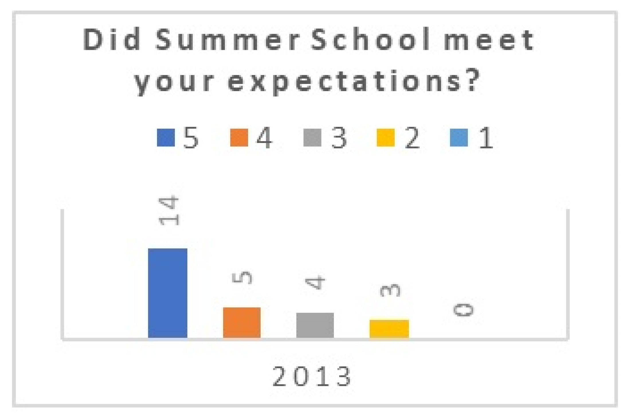
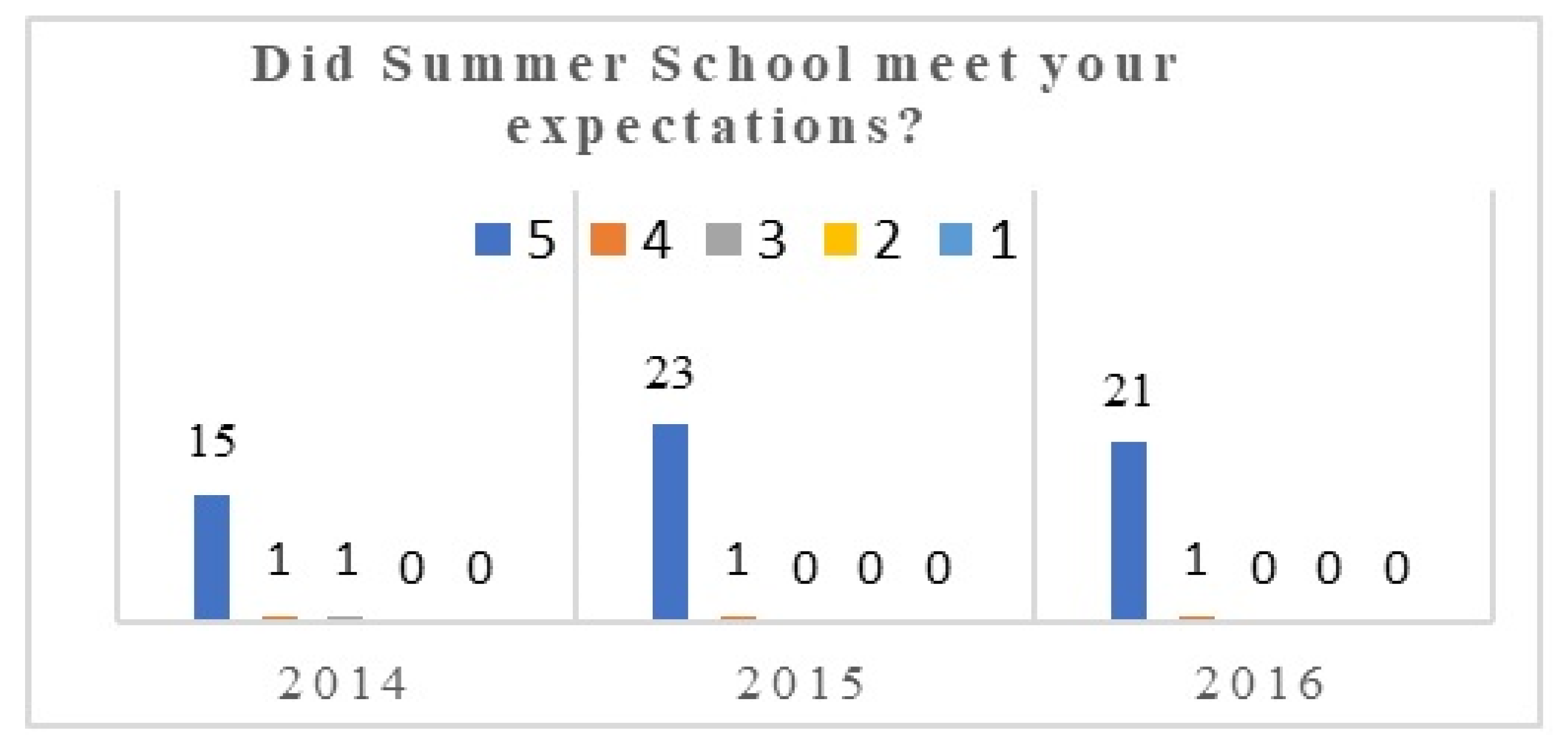
After the first survey, it was concluded that the students were mainly satisfied with what they learned at the Summer School (
Figure 1). However, individual comments implied the existence of shortcomings.
Upon survey analysis and oral evaluation, it was evident that the majority of students were unable to answer some of the fundamental questions, e.g., How is the trajectory of the robot axis movement translated from inner to outer coordinates generated by the CIROS program? How is dynamic gravity compensation performed? What kind of drive is used in a robot’s joints? What does the encoder signal look like?
These types of questions, asked during lab exercises, started an affirmative discussion on the reasons behind discrepancies between theory and practice at the Summer School and how to overcome them. Upon a performed analysis of the comments, it was evident that this issue was present at many universities because robot controllers did not allow one to measure the parameters. In other words, in lab exercises, students could not get a broader perspective of the robot control hierarchy.
The harmonization of the theoretical part of classes, which usually consists of a kinematic and dynamic robot overview, with the programming of actual, physical industrial robots was recognized as a challenge in improving the education process, which is of crucial importance but mainly put aside at technical universities, often behind R&D. It is often left in the realm of simulation [
13].
The proposal for the solution was the design of a simple didactic robot environment [
14] (Didactic Robot Environment—DRE) for robot programming and control. In the remainder of this paper, we present the design, the components and the motivation, and results in both a technical and educational sense.
In
Section 2, we present the design and implementation of this environment, with the rationale for its applicability in the pedagogical process, demonstrating which important concepts students learn from its components.
Section 3 introduces an exemplary control structure realized on our platform, and we verify its performance as a state-of-the-art control system for industrial robots. In
Section 4, we present the results of our educational study, demonstrating the success in bringing control and mechatronics closer to the summer school students after the introduction of an elaborate open architecture, as well as the educational results of using the environment in the teaching process. Finally,
Section 5 includes the conclusions of our study and a reflection on the current moment.
2. Materials and Methods
DRE was envisioned as an open student platform where robot control could be tested alongside students’ ability to perform measurements for all units of interest in lab exercises. As stated in [
15,
16], while designing DRE, we were guided by the following recommendations “Assertions that new knowledge is being contributed require significant understanding of prior contributions.” At the same time, we wanted to make a point regarding open architecture as a training tool for future professionals: if they continue using open architectures in their industry work or research, it will stimulate innovation, extend the useful life of machinery, cut costs and allow for repurposing, customization and extension [
17].
The methodology of the design and selection of components for the DRE environment is a feedback loop that includes the teaching objectives, accessibility of hardware and software, and relevance to the modern industrial practice: only with a balance and reinforcement of all three components can a platform like DRE have the potential to motivate students for work, explain basic concepts and readily prepare students to work with advanced structures built upon these basic concepts.
The DRE environment consists of three functional units:
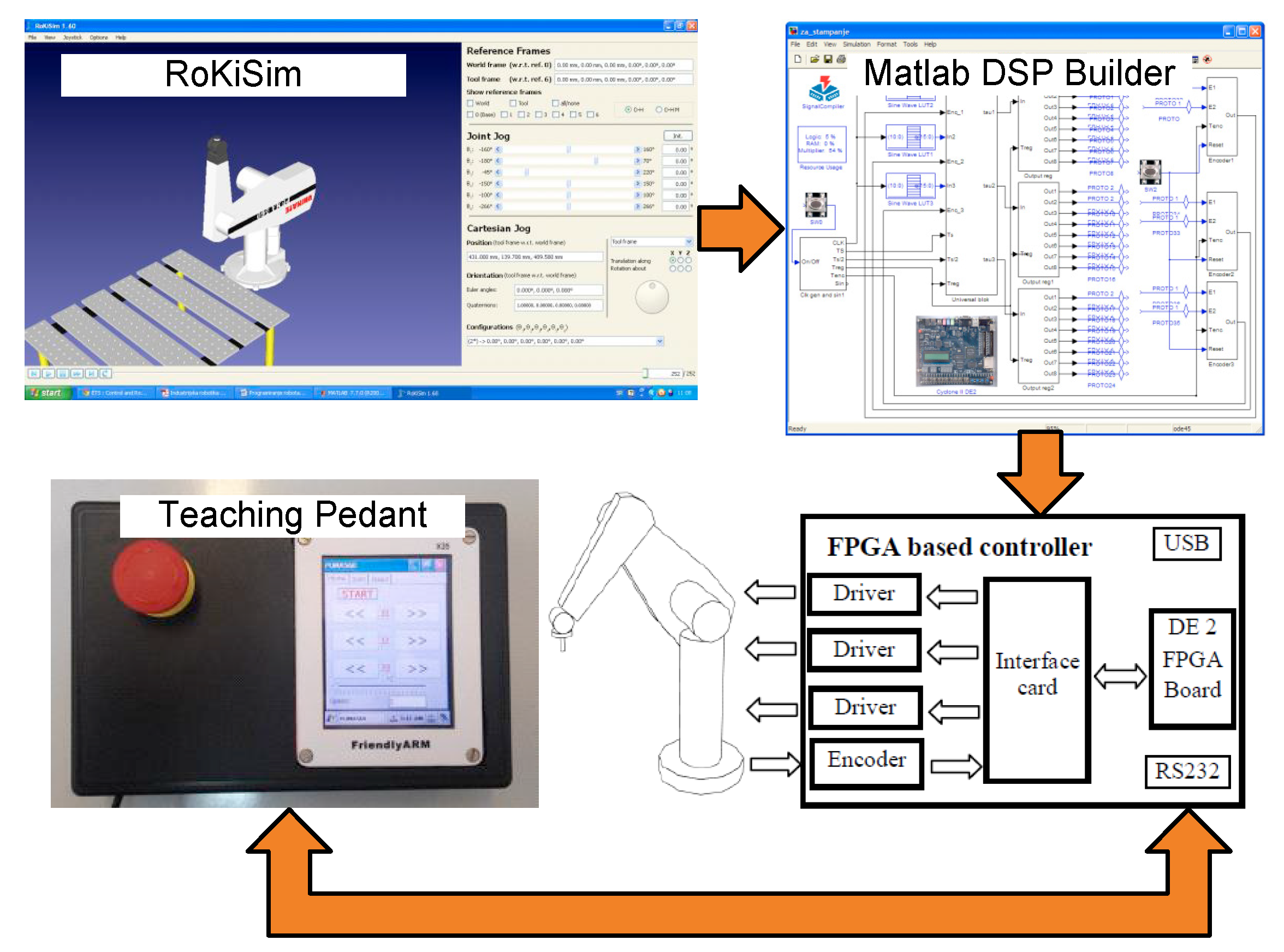
The block diagram in
Figure 2 represents the overall didactic environment for the programming and control of robot PUMA 560. Its computational basis consists of the field programmable gate array (FPGA)-based computing core with the program support on PC. Drawing experience from past robotics pedagogy [
18,
19,
20,
21,
22], PUMA 560 was chosen for probably being the best mathematically described robot in literature [
22], popular in labs worldwide for educational purposes.
2.1. Graphical Environment for Off-line Trajectory Generation of Robot Movement
The chosen initial platform for off-line trajectory generation was the RoKiSim simulator (
Figure 2), an easily accessible educational tool that was both free and available for different platforms. RoKiSim allowed for the 3D simulation of serial six-axis robots, with models of most popular robots by various manufacturers (e.g., ABB, Fanuc), including PUMA 560 (George Devol, KY, USA). It also possesses basic functions, such as a commercial virtual learning environment for simulating a wide range of applications in industrial robotics. From an educational point of view, the RoKiSim simulator is similar to CIROS Robot Studio, rendering the adaptation of students to a new environment straightforward. The main drawback of the RoKiSim simulator is its inability to generate a trajectory of the robot’s movement. In order to avoid this drawback, the MATLAB robotics toolbox [
23,
24] was used, generating a trajectory between positions.
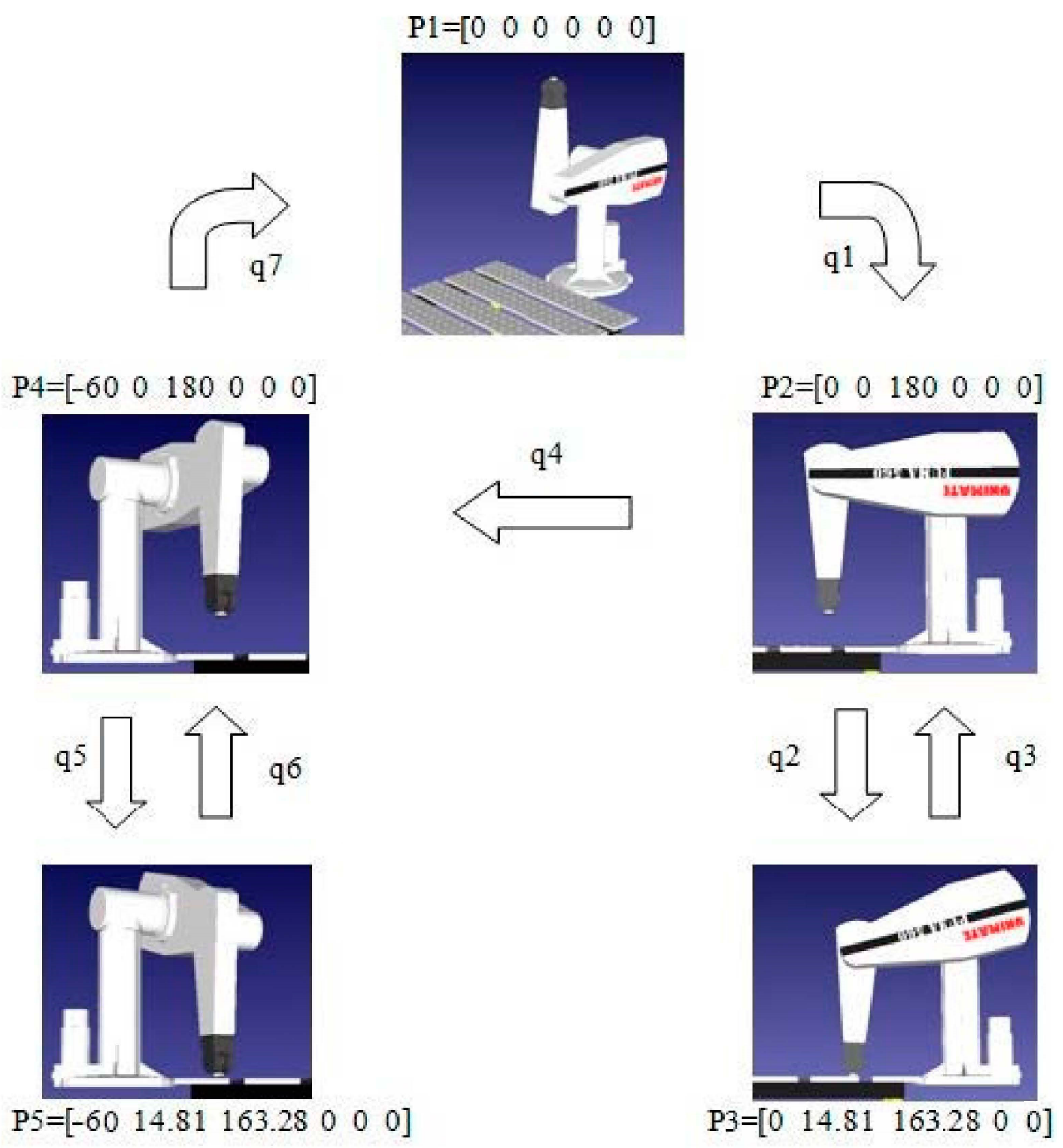
In a simple example, the goal of the robot (PUMA 560) was to perform the movement from starting position ‘home’ (P1) using maximum velocity to an auxiliary position (P2) above the working object, before approaching the object with reduced velocity (P3), taking the object and returning to the auxiliary position (P2). After that, the manipulator reached the auxiliary position (P4) with maximum velocity, followed by reaching the final position (P5) with reduced velocity. After leaving, the object was returned to the initial position ‘home’ (
Figure 3).
Repeating the procedure for the remaining positions, we obtained many individual trajectories, which were merged into the final trajectory. The final trajectory consisted of seven individual trajectories (q1–q7) between the positions (P1–P5).
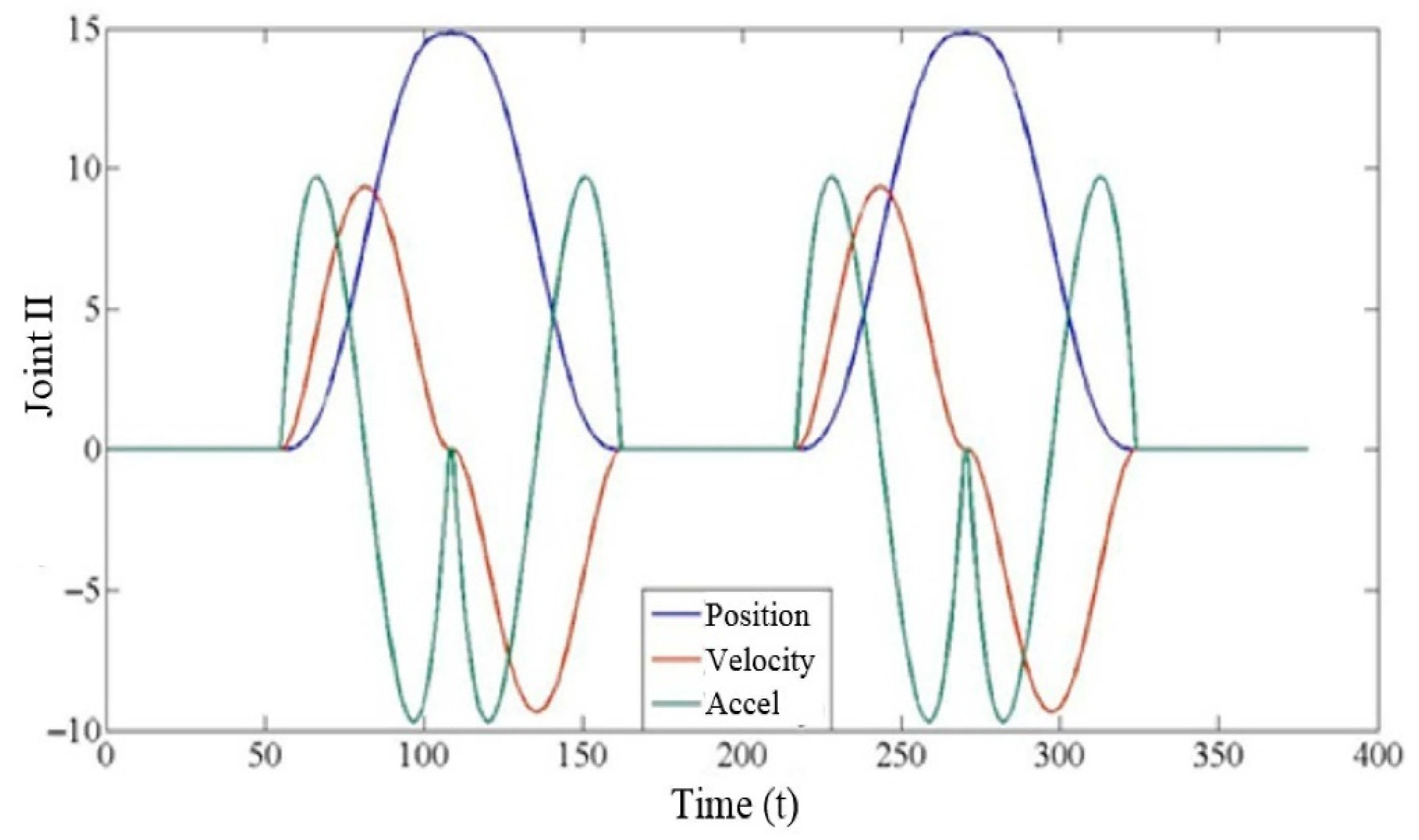
The diagram (
Figure 4) shows the generated trajectories for just one axis (II joint), which contain all the trajectory components: position (blue curve), velocity (red curve) and acceleration (green curve).
From
Figure 4, students should understand that:
These curves represent default values (referent values) of the control structures that control individual robot axes in inner coordinates;
This is a control issue—following the referent trajectory, which is far more difficult than maintaining the default value;
The continuousness of the functions describing joint positions and velocities (and, optionally, acceleration) is a design requirement;
Smoothness is a factor as well—avoiding nonsmooth interpolating trajectories if possible.
2.2. Didactic Robot Controller Architecture
The robot controller architecture design was motivated by its educational application. The controller has to be an open platform, which allows for simple programming and provides the students with an insight into all the components in the robot’s control structure.
With PC-based controllers, one serious drawback is the computation of the position control algorithm steps on general-purpose computing machinery. FPGA boards [
20,
25] offer dedicated real-time calculation hardware for these applications, which is simultaneously affordable and very safe to use. With the proliferation of FPGA chips, advanced software tools such as DSP Builder have been developed, allowing for the straightforward programming, adaptation and reconfiguration of control strategies on-board [
20,
25,
26].
The Didactic Robot Controller consists of four parts:
The controller with its components is shown in
Figure 5.
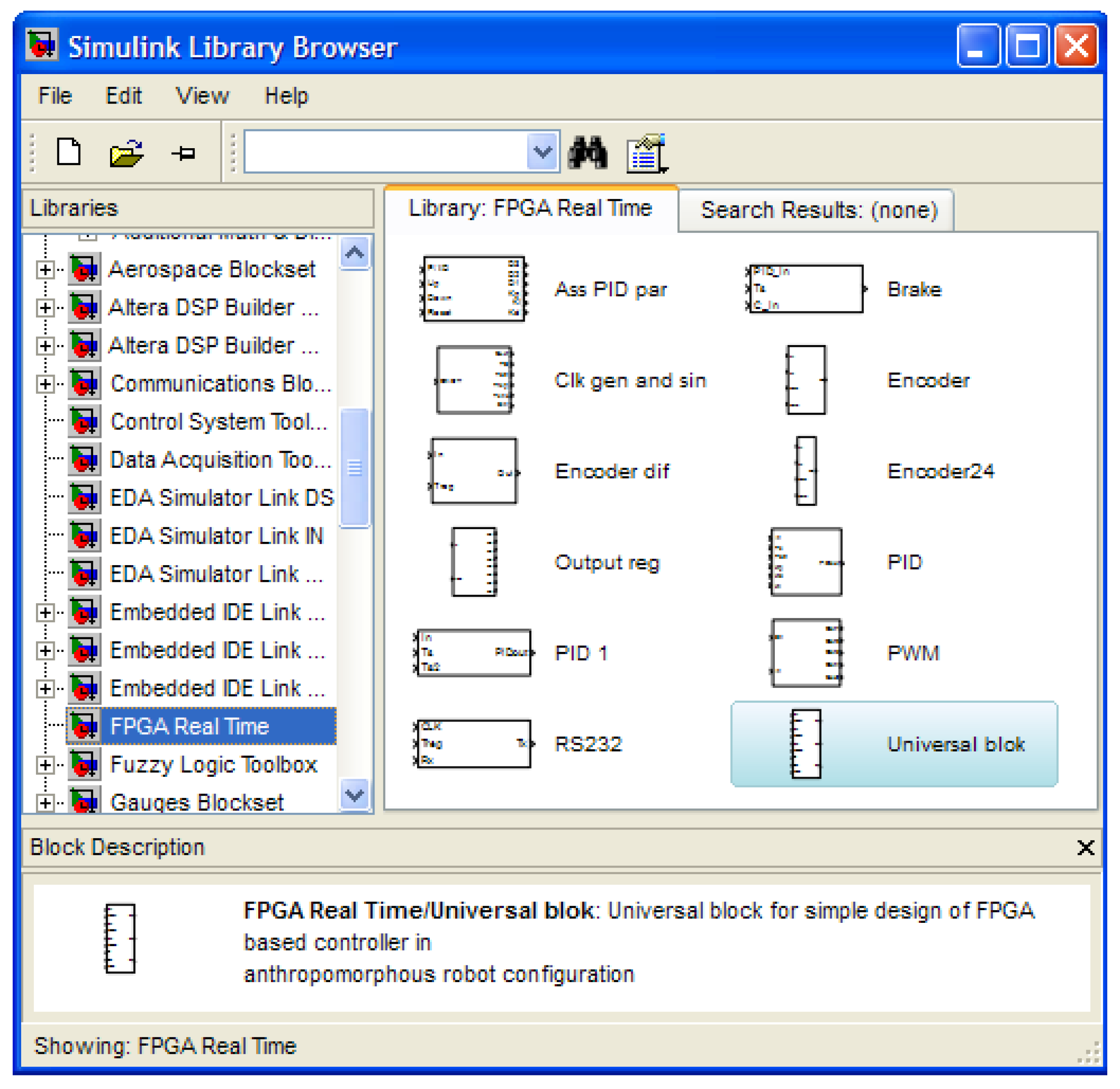
The trajectories generated by the RoKiSim simulator, complemented by the Matlab Robotic Toolbox, are the input data for the robot controller, which needs to ensure the desired robot’s movement. To provide a clear insight into all the components of a complex control structure, a user-friendly graphical environment in Matlab/Simulink was chosen, as presented in
Figure 6 [
27].
The robotics toolbox has the following blocks:
PID controller,
encoder interface,
velocity estimator,
output register (zero-order hold),
clock generator and sine wave generator,
PWM generator,
RS 232 interface,
Universal block for the simple design of the FPGA-based controller.
Before the implementation of the robot’s control structure itself, students were able to characterize the performance of the developed control structure by simulation, before downloading it to the FPGA computing core. This allowed them to access each part of the developed control structure and analyze all the relevant measurements of interest, which was not possible in conventional robot controllers. Finally, the abovementioned reasons were crucial for deciding to design a didactic robot controller. The example of the development of a complex control structure with a user-friendly toolbox was described in [
14,
28]. The RS-232 interface allows one to read variables from the robot control structure (PID regulator output, encoder output). With all the internal variables being available for observing and recording, the controller is fully open and represents, in an educational sense, an explainable, transparent white box that is suitable for scientific research and students’ education.
To connect the DE2 development board (FPGA computing core) with the rest of the system, an interface card was designed, with a D/A conversion, connection to the Teach pendant and logic level conversion.
The deployed driver for the PUMA 560 joint servo actuators is a four-quadrant power amplifier adapting the control signals from the FPGA computing core to the demands of the DC motor. Necessary torques for individual robot axes are calculated with the FPGA computing core as 8-bit numbers, DA-converted into the drive voltage signal [±10 V] and delivered at the driver input. Its output is connected to the DC motor, and the additional digital ‘enable’ input allows one to turn the driver on and off. We use three drivers to control the basic PUMA 560 configurations, and they are described in [
14].
2.3. The Teach Pendant
Robot programming using a simulator is a well-developed, popular method. However, the values for the positions obtained in the simulator are to a greater or lesser extent not in line with the real values. This problem is successfully solved by manually bringing the robot to the desired position using the control console. As the issue of signal acquisition and processing was solved entirely by the Encoder Interface block [
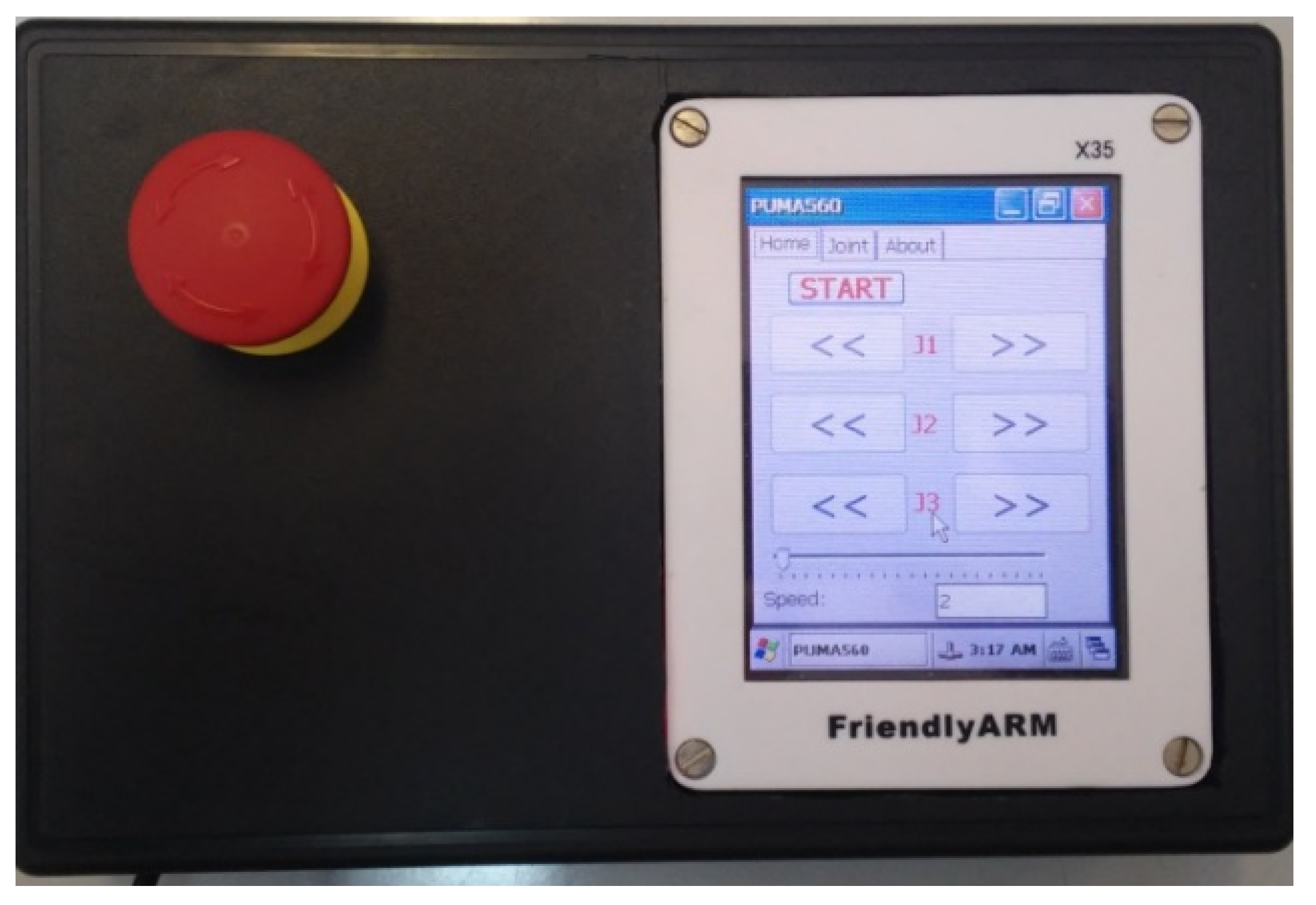
29], the idea which presented itself was to use the Teach pendant, which emulated the default values of the positions for all three robot axes as encoder impulses. The simple Teach Pendant is presented in
Figure 7.
The task of the Teach Pendant is a manual robot movement realized by generating series of pulses identical to the ones from the encoder (it generates strings of pulses 90 º -phase-shifted in the same manner as the encoder does). Depending on which string of pulses precedes, A or B, the direction changes accordingly. There are buttons on the touch screen that allow for the movement of three of the robot’s axes, whereas the velocity is controlled by an additional slide button.
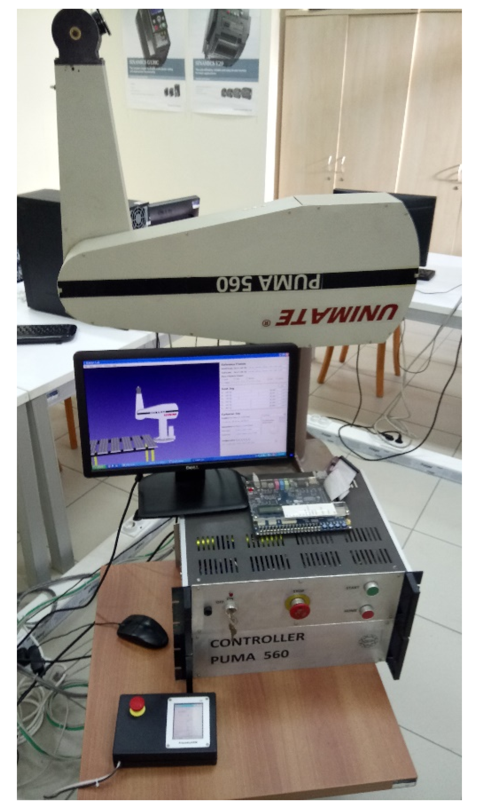
Figure 8 shows robot PUMA 560 with all the components mentioned above: the controller, Teach Pendant and dedicated graphic environment.
3. Results of the Control Architecture Verification
As a showcase, we use the PD control algorithm with gravity compensation for three robot axes of robot PUMA 560 [
30], represented schematically in
Figure 9.
The motivation for the PD comes from educational practice: a staple of manipulator controls in most frequently used textbooks [
30], easy to explain using concepts students have acquired in linear control courses and easy to implement structurally, PD has been repeatedly applied in the past to the PUMA and related robot arms in research, industry and education.
The trajectories q1, q2 and q3 were generated for the first three robot axes using the RoKiSim simulator and Matlab Robotic Toolbox. The structure was implemented by the developed Robotics Real Time Toolbox presented in
Figure 6. A detailed description of the control algorithm realization is given in [
9]. For details on the extraction of the parameters, the results of the experiments, the implementation and comparisons of the open hardware, and the software implementations of the control algorithm we use here, please see [
17].
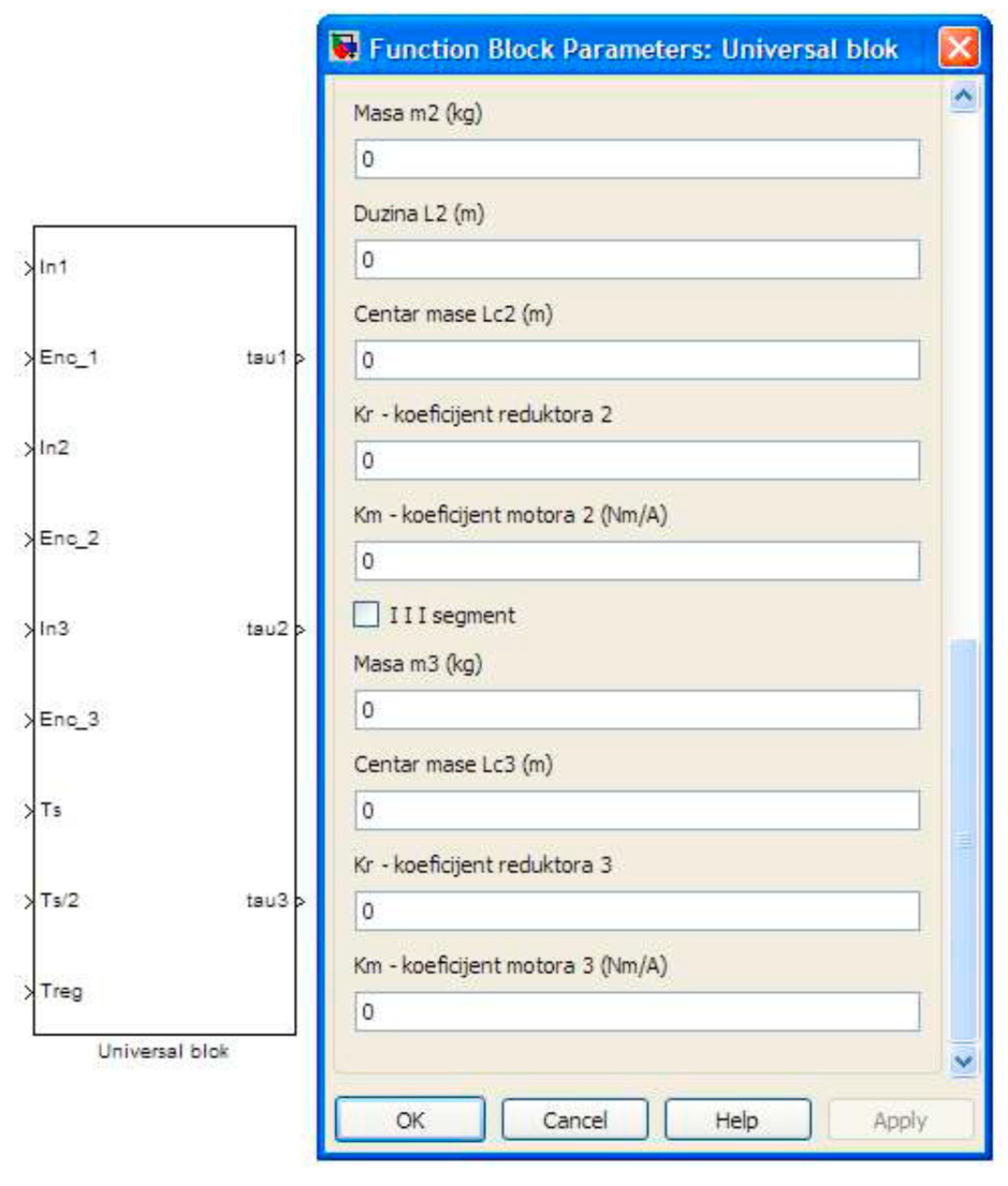
Figure 10 shows the interface of the critical component for this control structure, the Universal block for controlling the anthropomorphous three-axes robot configuration. It has three PID regulators, accompanied by a gravity compensation component for the second and the third axes, following the scheme in
Figure 9. Its inputs are basic robot parameters (mass, length and centroid position of the segments, as well as motor and transmission coefficients) and PID controller parameter values. Using the FPGA Real Time Toolbox (
Figure 6), it is possible to tune PIDs online, one axis at a time; here, the idea was to test the PID controller parameters for every axis, with the blocks from the Robotics Real Time Toolbox. The customization of the basic robot parameters allows for the realization of a complete three-axis control for any anthropomorphous robot.
As a test for following and reaching the desired position for the robot axes, we realized a trajectory using a seventh-degree polynomial (employing the function
jtraj). The task was reaching 1 rad and returning to the starting position, and a sample result of this experiment is shown in
Figure 11. Depending on different experimental conditions, the error in the steady-state varies: the maximum error that we observed at the steady-state was 1.2 mrad, but usually the errors were under 1 mrad (as depicted in
Figure 11) and realistically suitable for industrial purposes.
4. Results and Discussion of Educational Validation
A didactic robot controller was developed to provide a complete insight into all the components of a complex programming environment of an industrial robot for students. Such an approach enabled the students to use simple tools in order to generate desired trajectories for individual robot axes, to design specific types of robot control algorithms, and to verify the shape of generated movement momentums for drives of individual robot axes. They could also use oscilloscopes to see the waveforms of signals from the encoder, the shape of the motor current, which represents the generated momentum, and the PWM of the signals at the H-bridge output. All these signals are not available to students during lab exercises where standard industrial controllers are used.
The feedback loop of the evaluations was maintained through the subsequent editions of the summer school. Student surveys revealed that the gap between theory and practice in classes was reduced due to attending the Summer Schools entitled ‘Modern Mechatronic Systems’, as well as courses in Robotics and Automatization, Sensors and Actuators, and Modern Mechatronic Systems. The survey results also suggested that the students were more satisfied with the classes’ organization and that it met all their expectations (
Figure 12). The school hosted 89 students from 10 different regional universities over four years (36 female participants); they went ahead with their studies after graduation, and to the best of our knowledge, at least 32 obtained their master degrees, and at least nine have obtained a PhD degree or are nearing the end of their doctoral studies.
All the processes executed in the course of the industrial robot’s movement were explained in detail in the example of a point-to-point movement of the PUMA 560 robot. Students had the task to first move an end effector in XYZ space in a RoKiSim simulator before generating trajectories using MATLAB and Robotics Toolbox and memorizing them to LUT at FPGA. This exercise was beneficial because it provided the students with a better understanding of programming and using industrial robots, as stated in the survey. The questions that were asked were in the local language, and therefore they are not stated here, but the results that were obtained stated that this concept improved classes in industrial robotics.
Students’ suggestion for the new environment was to integrate the option for generating trajectories in RoKiSim together with GUI in order to render the process of generating referential trajectories more automated. This objection to the existing solution is justified and logical because the solutions developed at universities are in the majority of cases not as high-quality as the commercial ones. In courses, the best results would be achieved if the manufacturers of industrial robots offered an open structure, at least for older generations of robots.
5. Conclusions
This has been a practical study in mechatronics education, led by the hypothesis that an open, white-box approach to control improves the experience of students while not decreasing the relevance of the controller for the industrial applications that students are learning about: the performance and complexity of an open architecture controller remains at the professional level, but its explainability grows with the transparency of the design and student participation.
The results we presented in this paper are the verification and validation of our novel approach: verifying that the architecture works and validating its pedagogical performance with the students themselves.
It is hard not to reflect on the current moment in education with the COVID-19 pandemic, given the decreased opportunities for in-person teaching, massive group demonstrations of equipment, and necessity for blended and hybrid approaches to teaching, both online and offline. Closed architectures give little to work with: the possibility for sharing the software with students is limited, the hardware has to be run in person using custom interfaces, and individual remote work that can be done by students is not substantial, as they can neither investigate the structure of the hardware and software of such an architecture nor customize it. On the other hand, with the approach we take here, no time is wasted: both the software and hardware can be shared freely (available in the
Supplementary Materials accompanying this article) and customized remotely, and through those customizations it is not hard to design extensions that would also allow one to run experiments remotely.
