Article

Sensorless Voltage Observer for a Current-Fed High Step-Up DC-DC Converter Using Extended Kalman Filter

1
Department of Electrical and Electronics Engineering, Shiraz University of Technology, Shiraz 71557-13876, Iran
2
Electrical Engineering Section, Department of Mechanics and Electronics, University of Southern Denmark, 5230 Odense, Denmark
*
Authors to whom correspondence should be addressed.
Electronics 2020, 9(12), 2066; https://doi.org/10.3390/electronics9122066
Submission received: 12 October 2020 / Revised: 29 November 2020 / Accepted: 30 November 2020 / Published: 4 December 2020
(This article belongs to the Section Power Electronics)

Abstract

:
In high voltage applications, sensorless voltage control techniques can reduce the cost and increase the reliability of DC-DC converters. In this paper, a sensorless voltage observer for a current fed Cockcroft-Walton voltage multiplier is designed. The first step is to derive the converter model. Since any inaccuracy in the derived model can result in a discrepancy between the observed voltage and the actual output voltage, an accurate model is derived, which incorporates the influential elements. Then, two voltage observers based on the extended Kalman filter (EKF) are designed and used to estimate the output voltage, transformer magnetizing current and inductor current for two different configurations of the high step-up DC-DC converter. Experimental and simulation results of the system show the efficiency of the observers. The proposed observers represent good precision as the main parasitic parameters are considered in the converter model.

1. Introduction

During the past few decades, high-voltage DC power supplies have been widely used in industry, medicine, science, military, X-ray systems, dust filtering, insulating tests, and electrostatic coating. Today, most industrial high voltage loads are fed by line-commutated thyristor-based high voltage (HV) power supplies which are not able to provide optimal HV waveforms and are not cost-efficient in their processes [1]. The emerging topology for generating high DC voltage is shown in Figure 1. The interface system is a two-stage structure. The first stage is a diode rectifier which provides low DC voltage, then in the second stage, a switching-mode DC-DC converter boosts the DC voltage [2,3,4,5]. The wide applications of these switching-mode power supplies necessitate the design of precise, low cost and highly efficient DC-DC converters. However conventional voltage control strategies need to sample the output voltage using an accurate voltage sensor. Employing isolated high voltage DC-voltage sensors for isolated structures imposes more complexity, reduces reliability and adds extra hardware cost to the system. Thus, sensorless voltage control techniques, which are cost-effective and accurate enough, can be used. In order to apply sensorless voltage control, a voltage observer is used to estimate the output. It is very important to derive an accurate model of the converter since the precision of the system modelling affects the performance of the voltage observer and any inaccuracy in the derived model can deviate the observed voltage from the actual output voltage.
The extended Kalman filter (EKF) is used for observation of the output voltage. Since the 1960s, Kalman filter (KF) theory has been employed in many fields such as electrical engineering and robotics [6]. In electrical power engineering, KF and EKF have been widely used for observation purposes and parameter estimation in electric machines control and power electronic converters. KF and EKF are used for flux or speed estimation of induction motors in different control strategies such as direct torque control [7,8,9,10]. The rotor flux of the induction motor is estimated by using the stator voltages and currents and rotor speed measurement [11]. EKF has also received increasing attention in the estimation of different parameters of permanent magnet synchronous motors (PMSMs). For instance, in a PMSM, rotor speed and position has been estimated by using an EKF [12]. In order to decrease the computation resources, a reduced-order observer-based on EKF has been proposed which also enhances the estimation accuracy of the speed and rotor flux angle of a PMSM [13]. An EKF has been employed to estimate the speed of a PMSM in conjunction with an optimal method to adjust the matrices of EKF [14]. In order to attain sensorless speed control of a DC motor, the results of the speed estimation by using artificial neural network (ANN) and EKF have been compared in [15]. However, only simulation results have been proposed. The analysis of model-structure uncertainties effects on the robustness and performance of the Takagi-Sugeno observer and different types of Kalman filter for estimation of effective wind speed have been presented in [16]. Remaining useful life estimation of bearings under different operating conditions has been performed using an EKF [17]. In order to implement model predictive control for a boost converter in [18], the capacitor voltage and the inductor current of the converter have been estimated through an EKF. A Kalman filter has been used to consider variations of the load and minimize the steady-state error of the output voltage in control of the boost and synchronous step-down DC-DC converters [19,20,21]. The disturbances in the linearized model of a three phase inverter have been estimated in [22] by using a new derivative-free nonlinear Kalman Filter. In [23], the load current of a three-cell converter has been measured and the capacitor voltages have been estimated using a Kalman filter. Consequently, the number of voltage sensors has been reduced. The Capacitor voltages of modular multilevel converters have been estimated through an adaptive Kalman filter based observer in [24]. This method has also reduced the number of voltage sensors. Sliding mode control of a Single Ended Primary Inductor Converter (SEPIC) has been performed by applying an EKF for estimation of the state variables and variation of the load [25]. A sensorless predictive current control (PCC) strategy has been implemented by using EKF for a boost converter which is a second-order system [26]. Generally, other types of Kalman filter which can be applied to estimate converter voltage are as follows:
  • Kalman filter (KF): KF is applied to the linear systems, therefore its accuracy is limited to the operating point at which the converter can be modelled as a linear system.
  • Unscented Kalman filter (UKF): UKF is suitable for a highly nonlinear system. UKF uses unscented transformation (UT) to pick a minimal set of sample points around the mean value. It is used only in the cases that the extended Kalman filter can give particularly poor performance. In the paper, it is shown that EKF has an appropriate performance to estimate the converter voltage.
In some other researches, different types of KF are used for capacitor voltage estimation. In [27,28], KF is used for voltage estimation and applied in the voltage-balancing control of the multi-level converters and its performance is evaluated in [29]. In [27], the adaptive linear neuron (ADALINE) algorithm is employed for estimating of capacitor voltage in multi-level converters. One of the main constraints of using EKF for voltage estimation and control purposes is related to its computational burden. In [30], a method of computational complexity reduction in EKFs is proposed that is designed for systems with non-linear measurement models.
Recently, a current-fed high step-up DC-DC converter based on the Cockcroft-Walton Voltage Multiplier (CWVM) has been introduced to provide high DC voltage with several advantages as follows [31,32]:
  • Low and uniform stress per stage on diodes and capacitors.
  • Wide range of multiplication stages is achieved.
  • Compactness, low weight, and cost-efficiency.
  • Negative output through reversing diode polarity.
  • Low input current ripple.
  • Providing a part of the voltage gain by the current-fed circuit.
The output voltage of a current-fed high step-up CWVM DC-DC converter, which is a fourth-order system and more complicated compared to the investigated converters in the literature, is estimated in this paper. Moreover, since the output voltage of the converter is usually high, employing an isolated high voltage sensor can be very costly while reducing the system reliability. Hence, the voltage observer appears to be a viable alternative to the voltage sensor. In order to implement the voltage observer, an accurate model for each converter configuration, i.e., isolated type [33] and based on CWVM incorporating parasitic elements is proposed. According to the inherent nonlinearity of the converter, the extended Kalman filter (EKF) is proposed to estimate the output voltage, magnetizing current of the transformer (which is a key parameter to diagnose core saturation of the transformer) and the inductor current. Moreover, by employing a sampled current compensation method, the estimation error is minimized. Employing an accurate model of different kind of energy converters is considered for different purposes such as loss minimization [34,35,36]. In [34], the efficiency comparison of the SiC-MOSFET and Si-IGBT-based converters is performed for DC-DC interleaved converters considering a range of switching frequency and output inductances. Reference [35] is focused on a switched-capacitor version of the DC-DC buck converter. Two techniques for reducing top-plate parasitic loss are proposed. In [36], the power losses components are minimized using the particle swarm optimization method (PSO) to optimize the Single Ended Primary Inductor Converter (SEPIC) used in LED lighting applications.
This paper is organized as follows. The accurate mathematical model of the converter is derived in Section 2. Using the derived model, the voltage observer based on EKF is designed in Section 3. Then in Section 4, sampled current compensation is proposed. Finally, the experimental and simulation results and their analysis for an experimental prototype of the converter are given in Section 5.

2. Mathematical Model of the Converter

In this section, the structure of the converter with the voltage observer is presented and the accurate model of the converter is derived.

2.1. Control Structure of the System

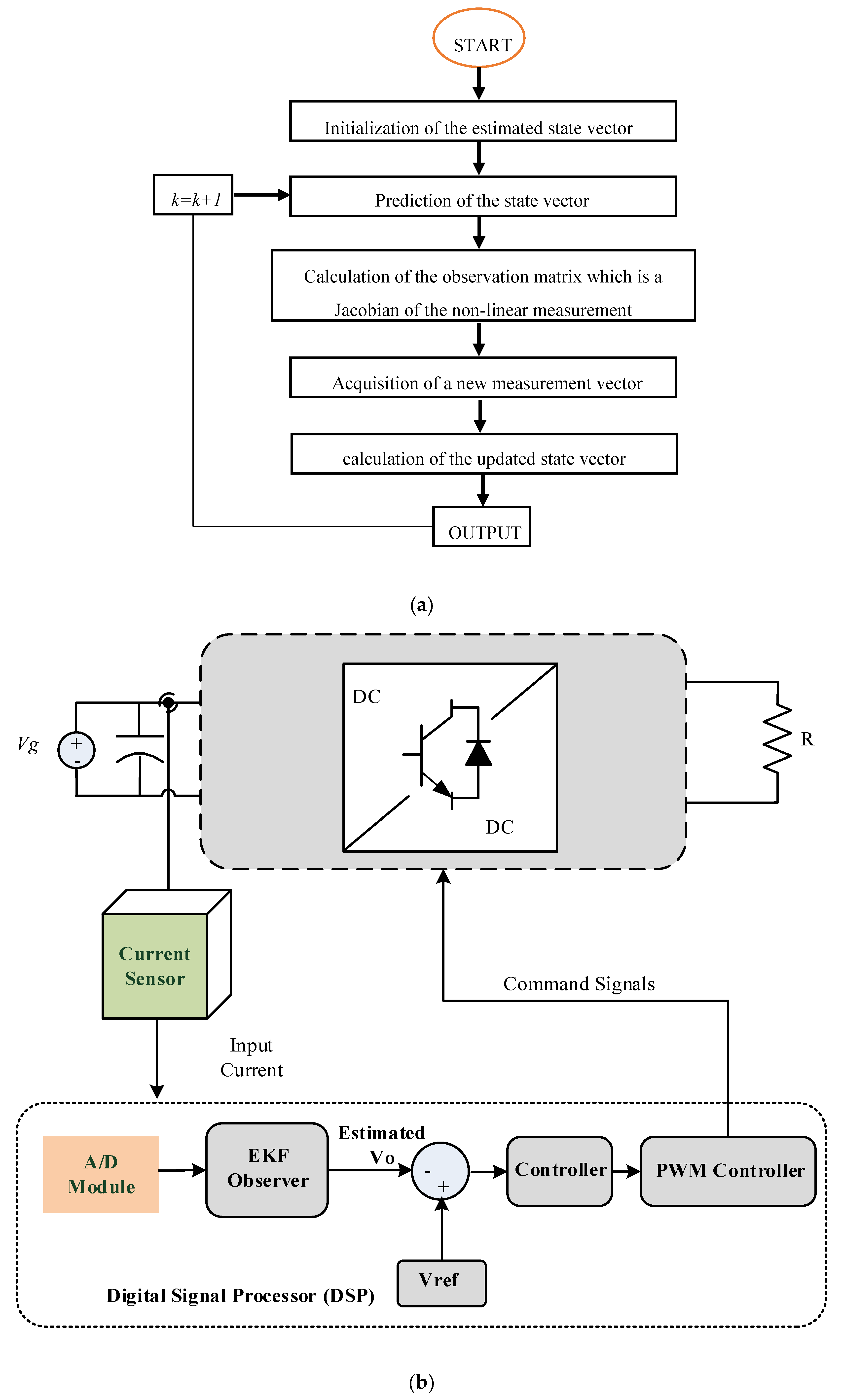
The structure of the converter (isolated type and based on CWVM) with the proposed voltage observer, is shown in Figure 2. The measured inductor current is used as the input of the observer.

2.2. The Precise Model of the Converter

Inaccuracy in the derived model of the converter can result in deviation of the observed voltage from the actual output voltage. Hence, for each configuration of the converter, the accurate model is derived, as follows.
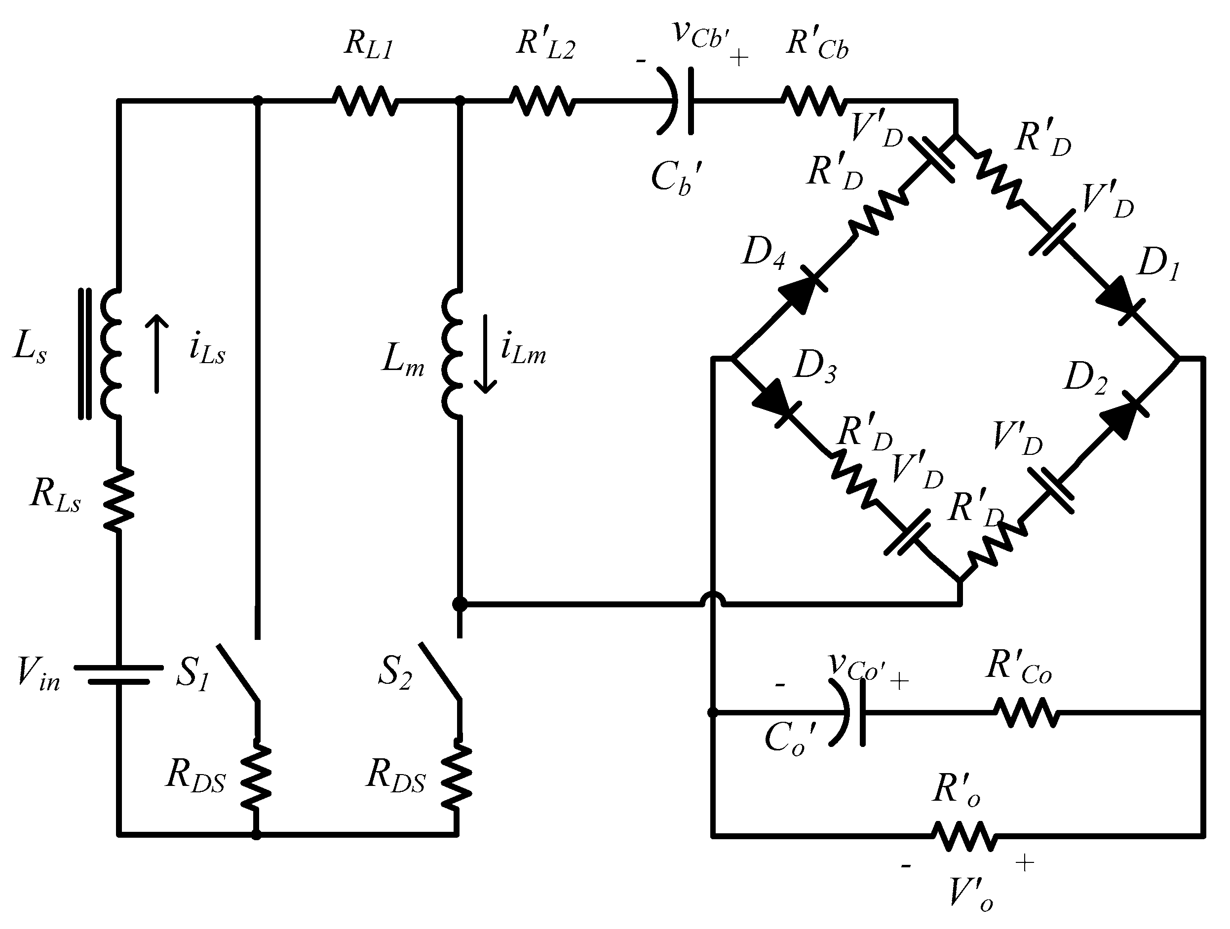
The equivalent circuit of the isolated type configuration in which the elements on the secondary side of the transformer are referred to as the primary side is shown in Figure 3.
The considered parasitic elements are as follows:
  • RLs: parasitic resistance of inductor Ls;
  • RL1: resistance of the transformer primary winding;
  • RDS: On-state resistance of the MOSFETs;
  • R’L2: secondary winding resistance of the transformer;
  • RD: conduction resistance of the diodes;
  • VD: forward voltage drop of diodes;
  • RCb: equivalent series resistances (ESR) of capacitor Cb;
  • RCo: equivalent series resistances (ESR) of capacitor Co.
The prime symbol () referred to as the primary side of the transformer.
The system state variables vector is:
x ( t ) = [ i L s ( t ) v C b ( t ) i L m ( t ) v C o ( t ) ] T
where iLs(t), vCb′(t), iLm(t) and vCo′(t) are inductance Ls current, capacitor Cb voltage, magnetizing inductance of the transformer Lm current and capacitor Co voltage, respectively.
In order to derive the dynamic model of the converter, several techniques can be applied. Here, the averaging technique is considered, in which the state space equations in different switching states are written and averaged in a switching cycle. The detailed description of the converter equations in different switching states are revealed in [31,37]. According to the state of the switches (ON/OFF), operation of the converter in a switching period (Ts) is divided into two states for a single-stage CW-VM. Using the conduction paths of the converter through capacitors and diodes in these switching states, the equations can be derived.
State I: S1: ON & S2: OFF, which lasts for dTs (d is the duty cycle). The voltage across L1 is equal to the input voltage (Vin); therefore, iL1 increases, while L2 transfers the stored energy to the CW-VM circuit. L2 is discharged with respect to the applied voltage.
State II: S1: OFF & S2: ON which lasts for (1 − d)Ts. In this state, energy stored in L1 during state I transfers to L2 and the CWVM; therefore, L1 and Co capacitors of CWVM are charged, and C1 is discharged.
Using the relations governed the converter, state-space models in the two states can be described; state I: KX = A1X + B1U, state II: KX = A2X + B2U. Large signal-averaged equations KX = AX + BU can be determined by the circuit averaging technique wherein A = dA1 + (1 − d)A2 and B = dB1 + (1 − d)B2.
The average state-space model of the system is obtained based on the assumption that the converter works in continuous conduction mode (CCM) as follows:
x ˙ ( t ) = A x ( t ) + B u ( t )
[ d i L s ( t ) d t d v C b ( t ) d t d i L m ( t ) d t d v C o ( t ) d t ] = [ A 11 D L s A 13 A 14 D C b 0 1 C b 0 A 31 1 L m A 33 A 34 D R o C o ( R o + R C o ) 0 ( 1 2 D ) R o C o ( R o + R C o ) 1 C o ( R o + R C o ) ] [ i L s ( t ) v C b ( t ) i L m ( t ) v C o ( t ) ] + [ 1 L s 2 D L s 0 0 0 2 ( 1 2 D ) L m 0 0 ] [ V i n V D ]
where
A 11 = ( R L s + R D S + D ( R L 1 + R L 2 + 2 R D + R C b + R o R C o R o + R C o ) ) L s
A 13 = D ( R L 2 + 2 R D + R C b + R o R C o R o + R C o ) L s
A 14 = D ( 1 R C o R o + R C o ) L s
A 31 = D ( R L 2 + 2 R D + R C b + R o R C o R o + R C o ) L m
A 33 = ( R L 2 + 2 R D + R C b + R o R C o R o + R C o ) L m
A 34 = ( 1 2 D ) ( 1 R C o R o + R C o ) L m
D = 1 D
D, Vin and Ro are duty ratio, input voltage, and the load resistance, respectively.
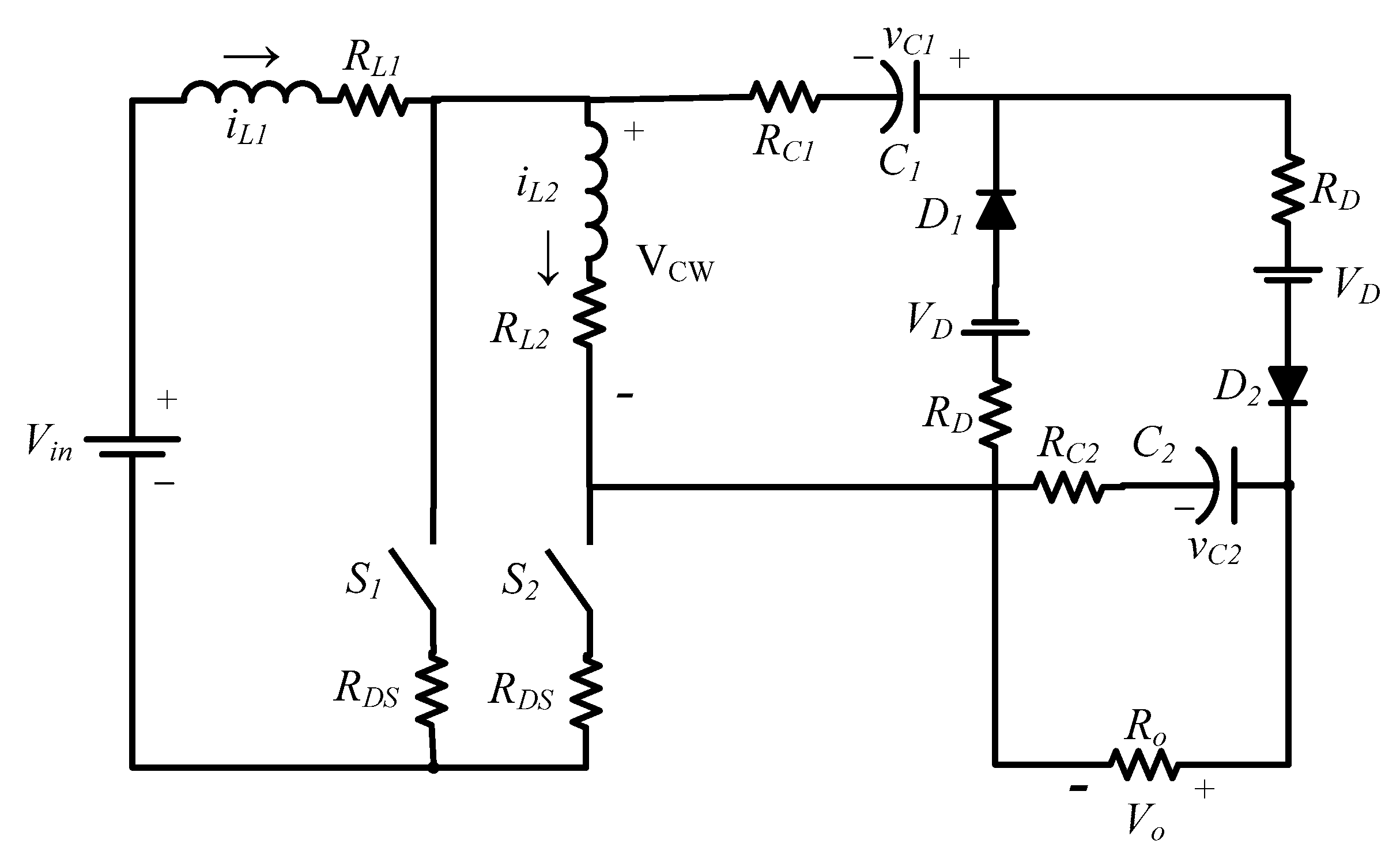
The equivalent circuit of the CWVM based converter is represented in Figure 4.
The considered parasitic elements are as follows: RL1 and RL2 are the resistance of inductor L1 and L2, respectively. RDS and RD are the conduction resistance of the MOSFETs and diodes, respectively. VD is the forward voltage drop of diodes and RC1 and RC2 are the equivalent series resistance (ESR) of C1 and C2, respectively. The state variables of the converter are shown by Equation (11).
x ( t ) = [ i L 1 ( t ) v C 1 ( t ) i L 2 ( t ) v C 2 ( t ) ] T
where iL1(t), vC1(t), iL2(t) and vC2(t) are L1 current, C1 voltage, L2 current and C2 voltage, respectively.
Assuming that the converter works in CCM, the average state-space model is obtained as follows:
[ d i L 1 ( t ) d t d v C 1 ( t ) d t d i L 2 ( t ) d t d v C 2 ( t ) d t ] = [ A 11 D L 1 A 13 A 14 D C 1 0 1 C 1 0 A 31 1 L 2 A 33 A 34 D R o C 2 ( R o + R C 2 ) 0 D R o C 2 ( R o + R C 2 ) 1 C 2 ( R o + R C 2 ) ] [ i L 1 ( t ) v C 1 ( t ) i L 2 ( t ) v C 2 ( t ) ] + [ 1 L 1 D L 1 0 0 0 1 2 D L 2 0 0 ] [ V i n V D ]
where
A 11 = ( R L 1 + R D S + D ( R D + R C 1 + R o R C 2 R o + R C 2 ) ) L 1
A 13 = D ( R D + R C 1 + R o R C 2 R o + R C 2 ) L 1
A 14 = D ( 1 R C 2 R o + R C 2 ) L 1
A 31 = D ( R D + R C 1 + R o R C 2 R o + R C 2 ) L 2
A 33 = ( R L 2 + R D + R C 1 + D ( R o R C 2 R o + R C 2 ) ) L 2
A 34 = D ( 1 R C 2 R o + R C 2 ) L 2
where Ro is the load resistance.

3. Proposed Voltage Estimation Strategy

According to the nonlinear behaviour of the foregoing DC-DC converter, EKF is used to estimate output voltage and noise filtering of the sampled inductor current. The EKF algorithm linearizes the nonlinear equations around the estimated values, and calculates the estimated values using the linearized equations.
In Section 2, the precise model of the converter has been derived. For the implementation of digital control, the first step is to transform the state equations to the discrete domain. The discrete state-space equation can be expressed as follows.
X [ k ] = f ( X [ k 1 ] , u [ k ] , w [ k 1 ] ) X [ k ] = e A T X [ k 1 ] + A 1 ( e A T I ) B u [ k ] + w [ k 1 ]
where u[k] is the system input at the kth sample time and T is the switching period. Since the forward Euler approximation method ( e A   T   > > I + A T ) causes the instability of the converter discrete model, the backward Euler approximation method is used ( e A   T   > > ( I A T ) 1 ). The measurement function is:
Z [ k ] = H X [ k ] + v [ k ]
where Z[k] is the measurement variable, i.e., the Ls current ILs[k] (or inductor L1 current IL1[k] in the second converter), and v[k] and w[k − 1] are process and measurement noises which take inaccuracies of the measurement and modelling into consideration, respectively. There is no coupling between these noises. H denotes the observation matrix (H = [1 0 0 0]).
The EKF algorithm consists of two phases: prediction and update. The states are predicted in the first phase by using a mathematical model of the system. Then, the predicted states are updated and refined by using actual states measurement in the second phase. According to Equation (19), the prediction stage of EKF is:
X ˜ [ k ] = ( I A T ) 1 X ^ [ k 1 ] + A 1 ( ( I A T ) 1   I ) B u [ k ] + w [ k 1 ]
P ˜ [ k ] = A [ k ] P [ k 1 ] A T ( k ) + Q
The state and covariance prediction relations are presented in (21) and (22) in which Q denotes the covariance of the process noise w[k]. X ˜ [k] and X ^ [k − 1] are prior and post-state estimations, of the kth and [k − 1]th switching periods, respectively. Similarly, P ˜ [k] and P[k − 1] are the prior and post estimation covariances of the kth and [k − 1]th switching periods. The Jacobian matrix of the process is A[k], which is given by:
A [ k ] = f ( X [ k 1 ] ) X [ k 1 ] = ( I A T ) 1
The updated measurement matrices of EKF are as follows:
G k = P ˜ [ k ] H T H P ˜ [ k ] H T + R
X ^ [ k ] = X ˜ [ k ] + G k ( Z [ k ] H X ˜ [ k ] )
P [ k ] = [ I G k H ] P ˜ [ k ]
The state and covariance update equations are presented in Equations (24)–(26) in which Gk and R are the Kalman filter gain and covariance of the measurement noise v[k], respectively. The output voltage can be estimated through the above process only by sampling Vin (input voltage) and iLs (or iL1 in the second configuration of the converter). Furthermore, the sampled inductor current can be filtered.
In order to estimate the average value of the output voltage, the observer needs the average value of the inductor current. Since the beginning of each switching period is considered as the sampling point of the current, the sampled current should be compensated to the average value. Considering is as the sampled current, then:
i s   = i v
where iv is the valley value of the inductor current. The average value of the inductor current (iav) can be obtained as follows:
i a v   = i v + 1 2 i p p
where ipp is the inductor current ripple which is calculated from Equation (29) for both configurations:
i p p = D V i n T L
Therefore, the compensation method can be given as:
i c o m p   = i s + 1 2 i p p
where ipp is obtained through the observer.
In Figure 5, a block diagram of the EKF implementation is shown.
Here, it is worth mentioning the main disadvantages of this technique for voltage estimation:
  • Requiring the accurate model of the converter. Some parameters that are not easy to be included in the model may affect the accuracy of the model: such as life derating of passive elements, frequency dependency of winding resistance, the nonlinearity of diode voltage drop and switch conduction resistance.
  • Computational budgetary: In every computational step of the EKF algorithm, the non-linear equations of the system model are linearized. Compared to the conventional system (using a voltage sensor), this method requires computation and estimation of the voltage value. Therefore, a digital processor is necessary to be employed in this technique.

4. Simulation & Experimental Results

Simulation and experimental tests are carried out and the results are shown in this section to prove the performance of the presented observer. The simulations are conducted for both ideal and non-ideal converters. A laboratory prototype for the CWVM based converter is provided and experimental tests are performed to specify the precision of the proposed voltage observer. The specifications are presented in Table 1 and Table 2.
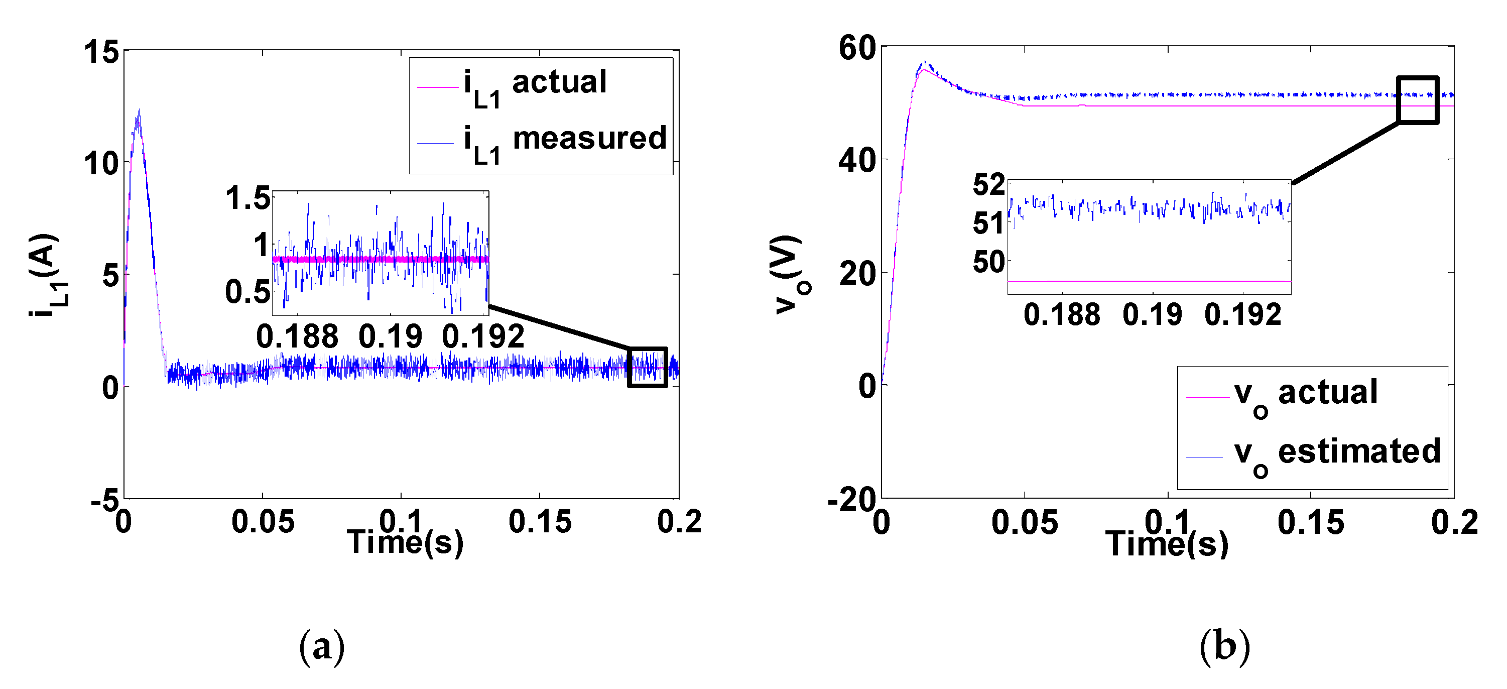
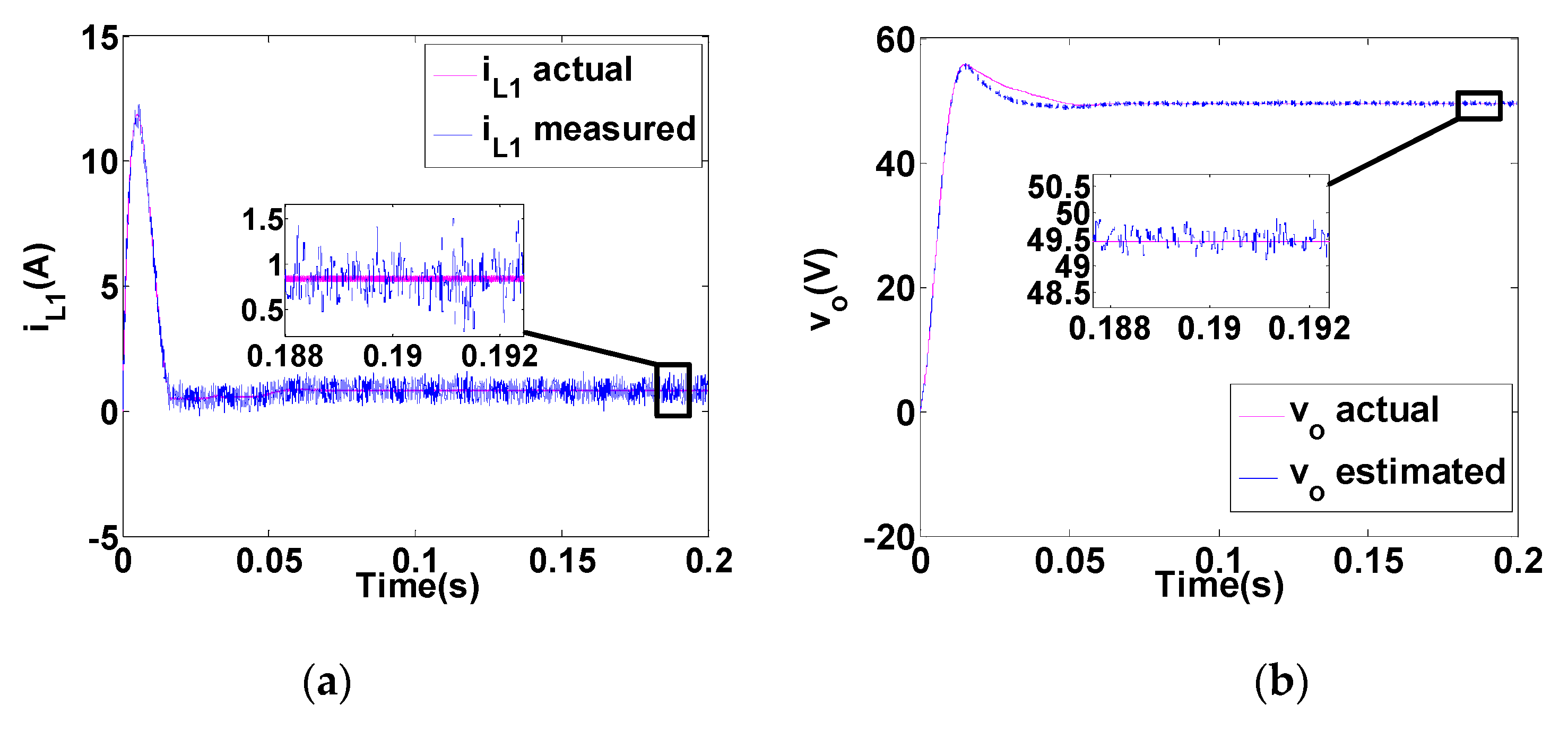
The simulation results are shown in Figure 6, Figure 7, Figure 8 and Figure 9. In order to simulate the actual conditions, besides the non-idealities of the converter that is included in the simulations, measurement noise is also considered for the current sensor. The results for the start-up transient of the converter are shown here. The load resistance is assumed to be 270 Ω.
Compensated sampled inductor current of L1 (iL1) for the simulated and accurate models of the converter are represented in Figure 6a or Figure 7a (Figure 6a for the ideal and Figure 7a for the non-ideal converter). The high-frequency variations in the measured iL1 are related to the simulated measurement noise. The proposed observer-based on EKF is used to estimate the output voltage, for which the results for actual and estimated values of Vo are shown in Figure 6b or Figure 7b (Figure 6b for the ideal and Figure 7b for the non-ideal converter). Considering these figures, two main results can be concluded:
  • Good consistency in the transient response of the actual and estimated results validates the derived dynamic model. Both results show the same settling time of 22 ms. The steady-state error of the estimated output voltage is 3% (1.5 V) for the ideal converter and 0.2% (0.1 V) for the non-ideal converter. The accurate model (including parasitic elements) is used for both simulations; therefore, the model is not accurate in ideal simulation, and this is the main reason for the greater error in Figure 6b.
  • Low variations of the estimated voltage (lower than 0.8 V) demonstrates that the proposed observer has filtered the measurement noise significantly.
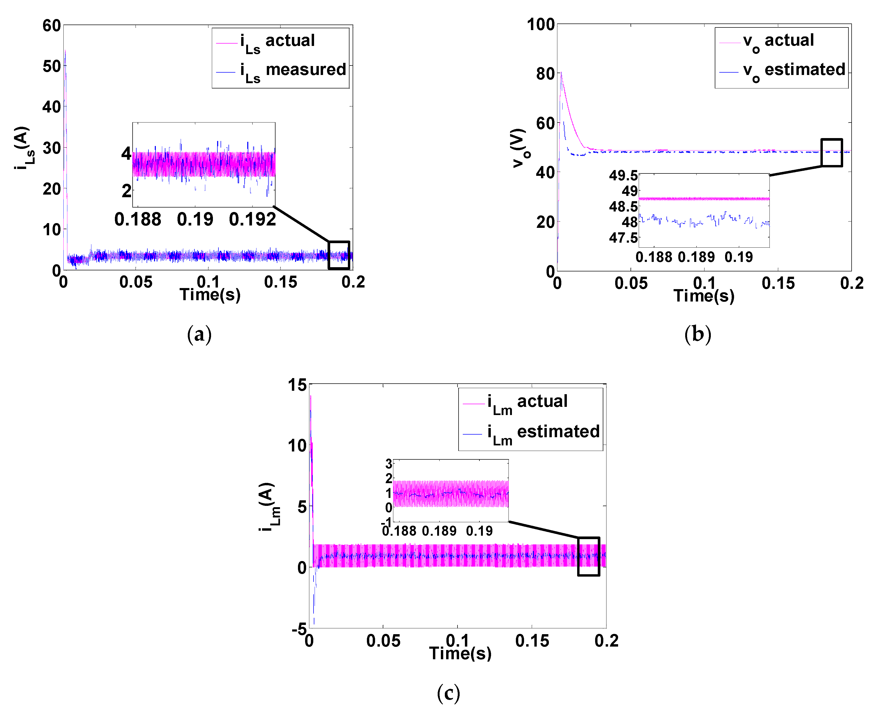
The same simulation scenario as described for the CWVM based converter (for which the results are shown in Figure 6 and Figure 7) is applied for a transformer-based converter, for which the output voltage is isolated. The results are shown in Figure 8 and Figure 9.
The compensated sampled inductor currents for the simple and accurate model of the converter are shown in Figure 8a (for the ideal converter) and Figure 9a (for the non-ideal converter). The steady-state error of the estimated output voltage for the simple and accurate model of the converter are about 2.3% (1.1 V) and 1.4% (0.7 V) considering Figure 8b or Figure 9b. Although the amount of error is acceptable, it is greater than the estimated error for the CWVM based converter. The difference is mainly because of the core loss, which is not included in the model. Another issue which should be considered for transformer-based converter is measuring the magnetizing current of the transformer (magnetizing inductance is modelled as L2). It must be estimated, as utilizing current sensor is not practical. The actual and estimated magnetizing inductor current for both simple and accurate models of the converter are also shown in Figure 8c (for the ideal converter) and Figure 9c (for the non-ideal converter). The steady-state errors of the estimated value of the magnetizing current are about 4.3% (40 mA) and 0.33 mA, respectively.
Simulation results for both configurations and the negligible errors between the actual and estimated values of the parameters demonstrate high accuracy (lower than 3% for output voltage and lower than 4.3% for magnetizing current in the worst conditions) and precision of the derived model of the converter and the observer.
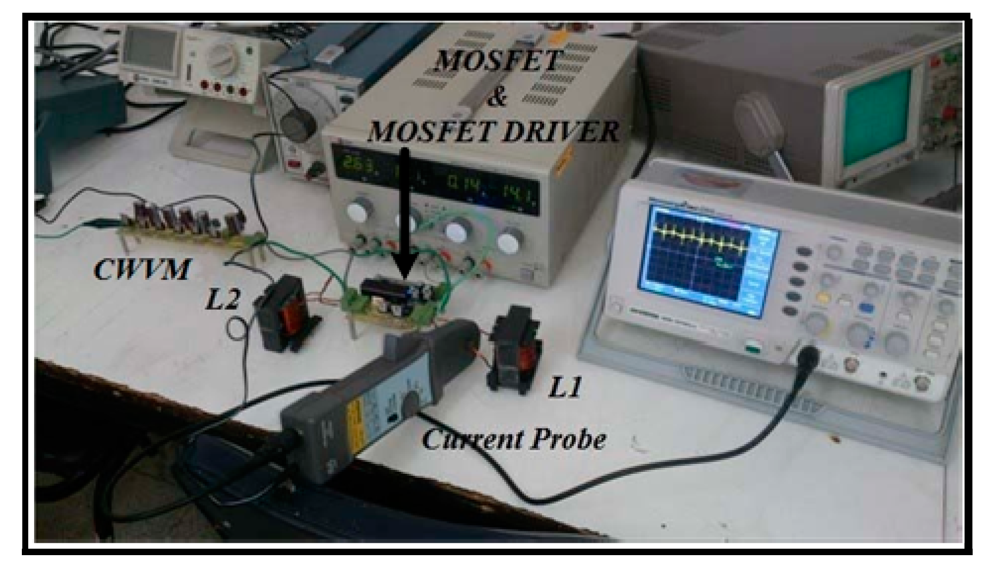
A laboratory prototype of the CWVM based converter with the specifications described in Table 1 is provided. The experimental set up is shown in Figure 10.
The following steps are taken to evaluate the practical performance of the observer.
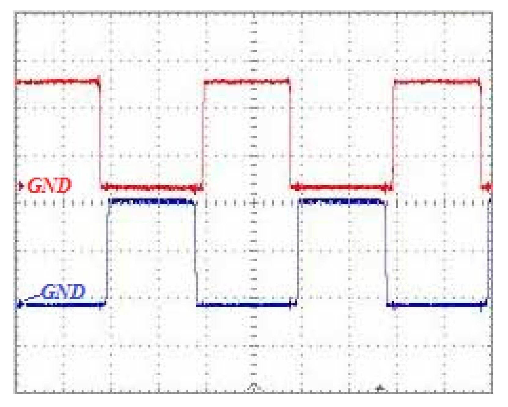
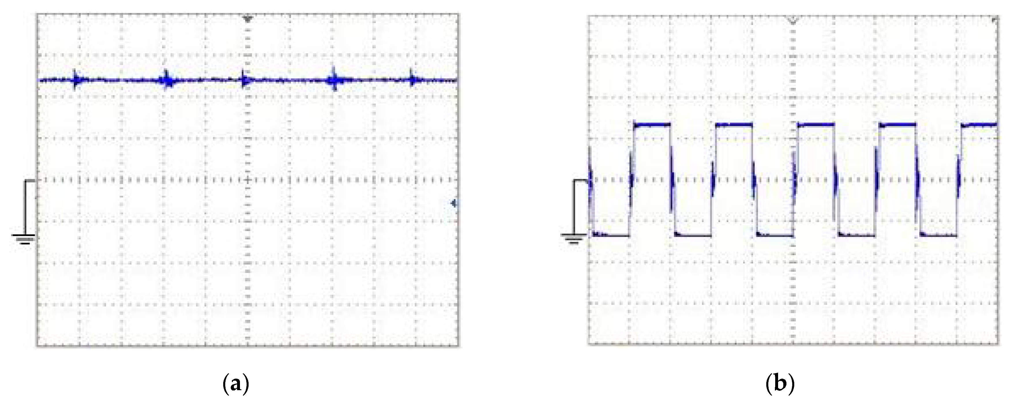
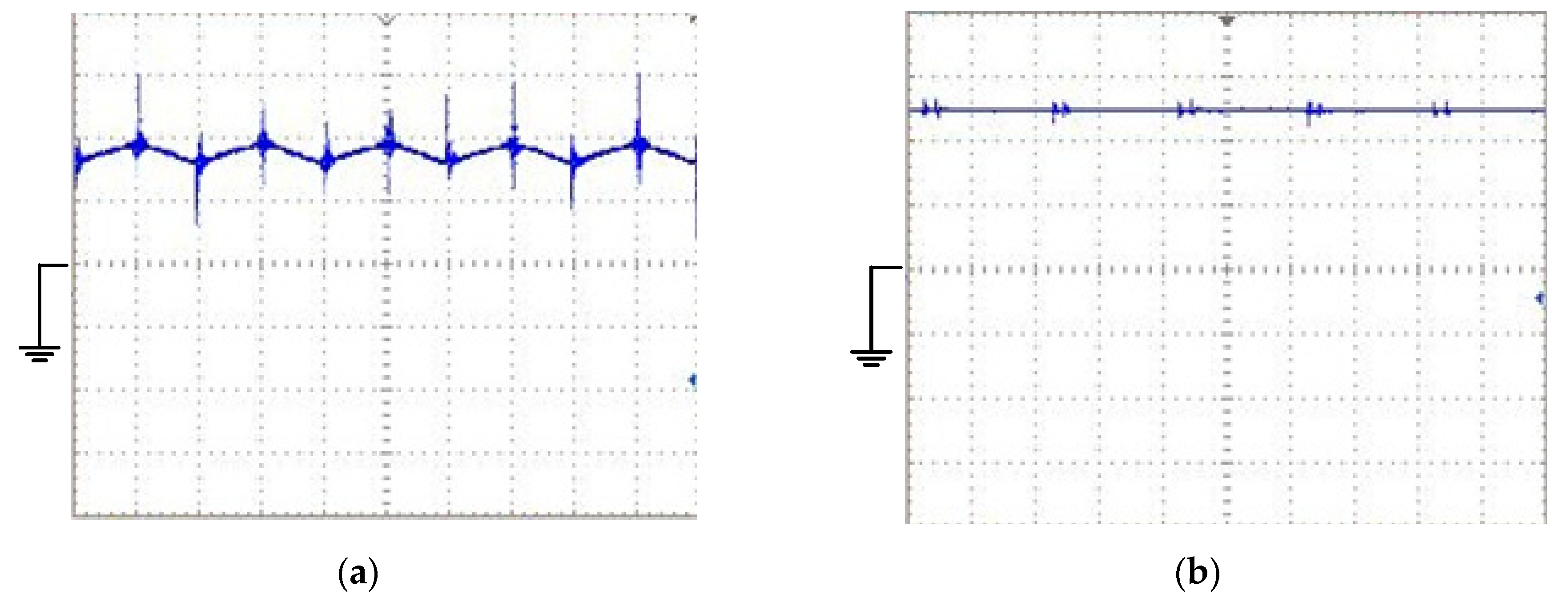
  • The converter is used to feed a resistive load. The value of load resistance is 270 Ω. The gating pulses are shown in Figure 11. In order to provide the required output voltage (50 V), the duty cycle is controlled to 45%. In addition, to provide safe commutation states, a sufficient overlap time (equal to 1 μs.) is considered for gating pulses. It is worth mentioning the state that both switches are off should be avoided [31]. The input voltage and CWVM voltage (VCW) of the converter are shown in Figure 12.
  • The current values of inductors are measured and a table of data for inductor currents are provided.
  • Using the practical measurements and presented observer, the output voltage is estimated and compared to the experimental result.
The experimental waveforms for the current of inductor L1 and output voltage are shown in Figure 13a,b, respectively. The steady-state value of the inductor current and the output voltage are measured as 0.875 A and 50.1 V, respectively.
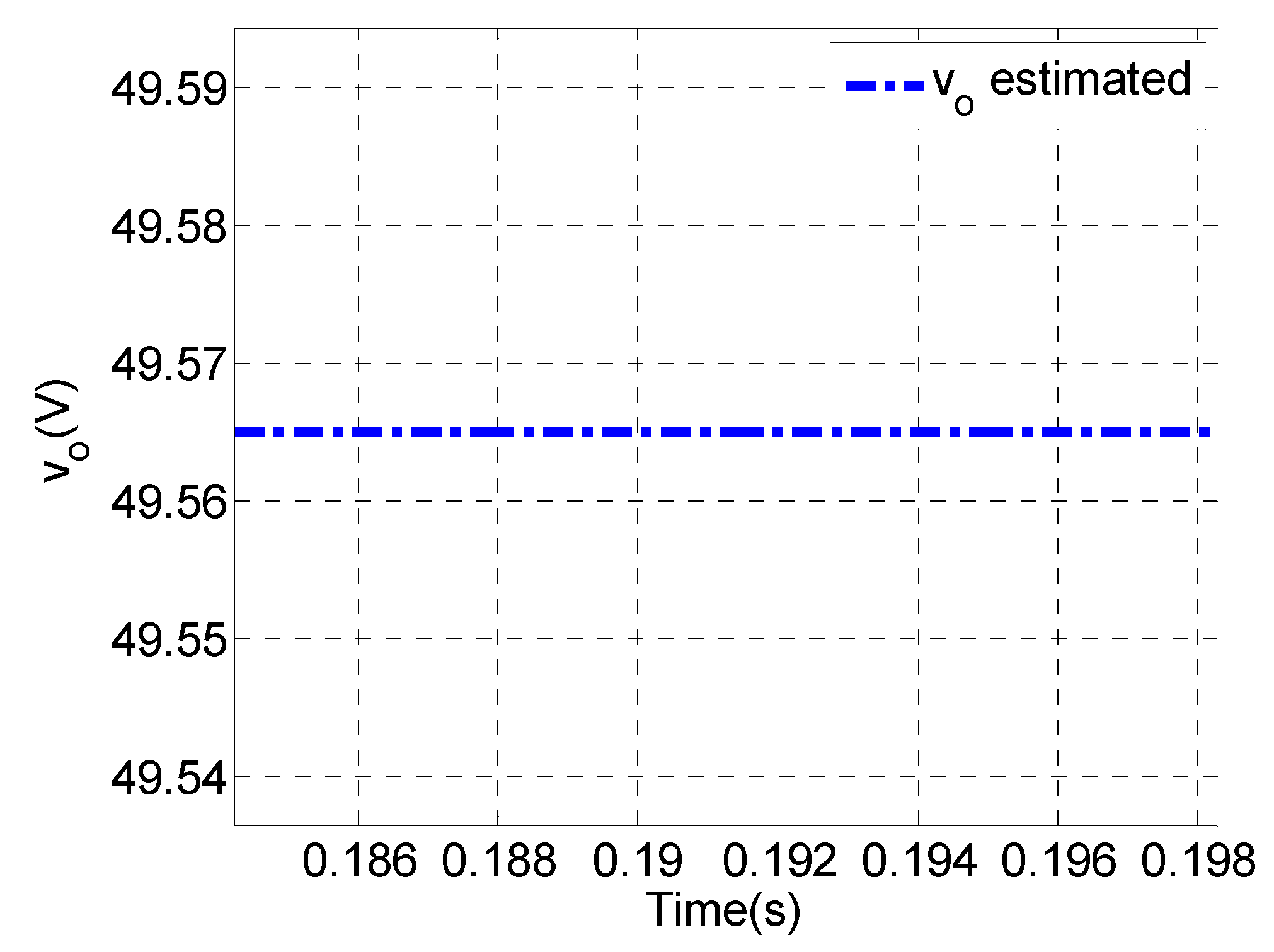
Using a digital oscilloscope, the current table of data is provided and used for estimating the output voltage. Comparing the actual value of the output voltage (Figure 13b) and the estimated output voltage (Figure 14) shows that the steady-state error of the estimated output voltage is 1.1% (0.53 V), which demonstrates the observer’s precision and good performance.

5. Conclusions

In this paper, a voltage observer for two different configurations of a current-fed step-up DC-DC converter was proposed. The voltage estimation was implemented using an EKF voltage observer based on the accurate model of the system. In the worst conditions, the estimation error was 3%. In addition, it was shown by simulations that a more accurate model results in a more precise estimation. While the converter parasitic parameters were included, the estimation error was lower than 1%. Therefore, considering the parasitic elements in the model is necessary for a highly accurate estimation. Measuring noise also added to the current in the simulations and the effect of the noise on estimation accuracy is also considered. The simulation results showed that the presented observer can filter the noise effectively. The experimental results also indicated that by sampling the inductor current and applying the proposed voltage observer, the observed voltage converged to the actual value of the voltage, and the steady-state error of the output voltage was also minimized since parasitic parameters are considered and the sampled inductor current was compensated. Therefore, the proposed voltage observer can be used to eliminate the need for expensive high voltage sensors in high gain step-up DC-DC converters and also for measurement noise filtering. Two major limitations of using the observer are the accuracy of the dynamic model and required digital processor, and the computational burden.

Author Contributions

Investigation, K.H. and A.R. (Amirhossein Rajaei); methodology, K.H. and A.R. (Akbar Rahideh); supervision, A.R. (Amirhossein Rajaei); writing—original draft preparation, A.R. (Amirhossein Rajaei); writing—review and editing, M.S. All authors have read and agreed to the published version of the manuscript.

Funding

This research received no external funding.

Conflicts of Interest

The authors declare no conflict of interest.

References

  1. Grass, N.; Hartmann, W.; Klockner, M. Application of Different Types of High-Voltage Supplies on Industrial Electrostatic Precipitators. IEEE Trans. Ind. Appl. 2004, 40, 1513–1520. [Google Scholar] [CrossRef]
  2. Soeiro, T.; Biela, J.; Linner, J.; Ranstad, P.; Kolar, J. Line power quality improvement for pulsed Electrostatic Precipitator systems. In Proceedings of the 2010 International Power Electronics Conference—ECCE ASIA, Sapporo, Japan, 21–24 June 2010. [Google Scholar]
  3. Gavin, S.; Paolone, M.; Biner, H.; Ecoeur, P.; Louokdom, E.; Carpita, M. A Digitally Controlled 125 kVdc, 30 kW Power Supply with an LCC Resonant Converter Working at Variable DC-link Voltage: Full Scale Prototype Test Results. In Proceedings of the 7th IET International Conference on Power Electronics, Machines and Drives (PEMD 2014), Manchester, UK, 8–10 April 2014. [Google Scholar]
  4. Park, Y.; Jung, B.; Choi, S. Nonisolated ZVZCS Resonant PWM DC–DC Converter for High Step-Up and High-Power Applications. IEEE Trans. Power Electron. 2012, 27, 3568–3575. [Google Scholar] [CrossRef]
  5. Soeiro, T.B.; Mühlethaler, J.; Linnér, J.; Ranstad, P.; Kolar, J.W. Automated Design of a High-Power High-Frequency LCC Resonant Converter for Electrostatic Precipitators. IEEE Trans. Ind. Electron. 2013, 60, 4805–4819. [Google Scholar] [CrossRef]
  6. Bulut, Y. Applied Kalman Filter Theory; Northeastern University: Boston, MA, USA, 2011. [Google Scholar]
  7. Alsofyani, I.M.; Idris, N.R.N. Lookup-table-based DTC of induction machines with improved flux regulation and extended Kalman filter state estimator at low-speed operation. IEEE Trans. Ind. Inform. 2016, 12, 1412–1425. [Google Scholar] [CrossRef]
  8. Singh, M. Extended Kalman Filter based Speed Estimation for the Control of PMSG. In Proceedings of the IEEE 15th Brazilian Power Electronics Conference and 5th IEEE Southern Power Electronics Conference (COBEP/SPEC), Santos, Brazil, 1–4 December 2019; pp. 1–6. [Google Scholar]
  9. Ouhrouche, M.; Errouissi, R.; Trzynadlowski, A.M.; Tehrani, K.A.; Benzaioua, A. A novel predictive direct torque controller for induction motor drives. IEEE Trans. Ind. Electron. 2016, 63, 5221–5230. [Google Scholar] [CrossRef]
  10. Ortatepe, Z.; Karaarslan, A. Extended Kalman Filter Design for Model Predictive Current Controlled DFIG. In Proceedings of the 11th International Conference on Electrical and Electronics Engineering (ELECO), Bursa, Turkey, 28–30 November 2019; pp. 305–310. [Google Scholar]
  11. Salvatore, L.; Stasi, S.; Tarchioni, L. A new EKF-based algorithm for flux estimation in induction machines. IEEE Trans. Ind. Electron. 1993, 40, 496–504. [Google Scholar] [CrossRef]
  12. Janiszewski, D. Extended Kalman filter based speed sensorless PMSM control with load reconstruction. In Proceedings of the IECON 2006—32nd Annual Conference on IEEE Industrial Electronics, Paris, France, 6–10 November 2006; pp. 1465–1468. [Google Scholar]
  13. Quang, N.K.; Hieu, N.T.; Ha, Q.P. FPGA-based sensorless PMSM speed control using reduced-order extended Kalman filters. IEEE Trans. Ind. Electron. 2014, 61, 6574–6582. [Google Scholar] [CrossRef]
  14. Xu, D.; Zhang, S.; Liu, J. Very-low speed control of PMSM based on EKF estimation with closed loop optimized parameters. ISA Trans. 2013, 52, 835–843. [Google Scholar] [CrossRef]
  15. Aydogmus, Z.; Aydogmus, O. A comparison of artificial neural network and extended Kalman filter based sensorless speed estimation. Measurement 2015, 63, 152–158. [Google Scholar] [CrossRef]
  16. Gauterin, E.; Kammerer, P.; Kühn, M.; Schulte, H. Effective wind speed estimation: Comparison between Kalman filter and Takagi–Sugeno observer techniques. ISA Trans. 2016, 62, 60–72. [Google Scholar] [CrossRef]
  17. Singleton, R.K.; Strangas, E.G.; Aviyente, S. Extended Kalman filtering for remaining-useful-life estimation of bearings. IEEE Trans. Ind. Electron. 2015, 62, 1781–1790. [Google Scholar] [CrossRef]
  18. Beccuti, A.G.; Mariethoz, S.; Cliquennois, S.; Wang, S.; Morari, M. Explicit model predictive control of DC-DC switched-mode power supplies with extended Kalman filtering. IEEE Trans. Ind. Electron. 2009, 56, 1864–1874. [Google Scholar] [CrossRef]
  19. Geyer, T.; Papafotiou, G.; Frasca, R.; Morari, M. Constrained optimal control of the step-down DC-DC converter. IEEE Trans. Power Electron. 2008, 23, 2454–2464. [Google Scholar] [CrossRef]
  20. Karamanakos, P.; Geyer, T.; Manias, S. Direct voltage control of DC-DC boost converters using model predictive control based on enumeration. In Proceedings of the Power Electronics and Motion Control Conference (EPE/PEMC), Novi Sad, Serbia, 4–6 September 2012; pp. 10–18. [Google Scholar]
  21. Geyer, T.; Papafotiou, G.; Morari, M. Hybrid model predictive control of the step-down DC-DC converter. IEEE Trans. Contr. Syst. Technol. 2008, 16, 1112–1124. [Google Scholar] [CrossRef]
  22. Rigatos, G.G.; Siano, P.; Zervos, N.; Cecati, C. Derivative-free nonlinear Kalman Filtering for control of three-phase voltage source converters. In Proceedings of the Industrial Electronics Society, IECON 2013—39th Annual Conference of the IEEE, Vienna, Austria, 10–13 November 2013; pp. 7598–7603. [Google Scholar]
  23. Bensaid, R.; Fadel, M. Floating voltages estimation in three-cell converters using a discrete-time Kalman filter. In Proceedings of the 2001 IEEE 32nd Annual Power Electronics Specialists Conference, PESC, Vancouver, BC, Canada, 17–21 June 2001; pp. 327–332. [Google Scholar]
  24. Abushafa, O.; Gadoue, S.; Dhaidah, M.; Aktinson, D. Capacitor voltage estimation in modular multilevel converters using a Kalman filter algorithm. In Proceedings of the IEEE International Conference on Industrial Technology (ICIT), Seville, Spain, 17–19 March 2015; pp. 3016–3021. [Google Scholar]
  25. Li, N.; Lin-Shi, X.; Lefranc, P.; Godoy, E.; Jaafar, A. FPGA based sliding mode control for high frequency SEPIC. In Proceedings of the IEEE International Symposium on Industrial Electronics, Gdansk, Poland, 27–30 June 2011; pp. 1575–1580. [Google Scholar]
  26. Tong, Q.; Chen, C.; Zhang, Q.; Zou, X. A sensorless predictive current controlled boost converter by using an EKF with load variation effect elimination function. Sensors 2015, 15, 9986. [Google Scholar] [CrossRef] [PubMed] [Green Version]
  27. Abdelsalam, M.; Tennakoon, S.; Diab, H.; Marei, M.I. An ADALINE based capacitor voltage estimation algorithm for modular multilevel converters. In Proceedings of the 2016 19th International Symposium on Electrical Apparatus and Technologies (SIELA), Bourgas, Bulgaria, 29 May–1 June 2016; p. 2. [Google Scholar] [CrossRef]
  28. Islam, M.D.; Razzaghi, R.; Bahrani, B. Arm-Sensorless Sub-Module Voltage Estimation and Balancing of Modular Multilevel Converters. IEEE Trans. Power Deliv. 2020, 35, 957–967. [Google Scholar] [CrossRef]
  29. Galarza, J. Study of the estimated capacitor voltage by kalman filter for a modular multi-level converter. In Proceedings of the 2019 IEEE XXVI International Conference on Electronics, Electrical Engineering and Computing (INTERCON), Lima, Peru, 12–14 August 2019. [Google Scholar] [CrossRef]
  30. Kaniewski, P. Extended Kalman filter with reduced computational demands for systems with non-linear measurement models. Sensors 2020, 20, 1584. [Google Scholar] [CrossRef] [Green Version]
  31. Rajaei, A.; Khazan, R.; Mahmoudian, M.; Mardaneh, M.; Gitizadeh, M. A Dual Inductor High Step-Up DC/DC Converter Based on the Cockcroft–Walton Multiplier. IEEE Trans. Power Electron. 2018, 33, 9699–9709. [Google Scholar] [CrossRef]
  32. Müller, L.; Kimball, J.W. High Gain DC–DC Converter Based on the Cockcroft–Walton Multiplier. IEEE Trans. Power Electron. 2016, 31, 6405–6415. [Google Scholar] [CrossRef]
  33. Mantovanelli, P.; Barbi, I. A new current-fed, isolated PWM DC-DC converter. IEEE Trans. Power Electron. 1996, 11, 431–438. [Google Scholar] [CrossRef]
  34. Loncarski, J.; Monopoli, V.G.; Cascella, G.L.; Cupertino, F. SiC-MOSFET and Si-IGBT-Based dc-dc interleaved converters for EV chargers: Approach for efficiency comparison with minimum switching losses based on complete parasitic modeling. Energies 2020, 13, 4585. [Google Scholar] [CrossRef]
  35. Biswas, A.; Kar, M.; Mandal, P. Techniques for reducing parasitic loss in switched-capacitor based DC-DC converter. In Proceedings of the 2013 Twenty-Eighth Annual IEEE Applied Power Electronics Conference and Exposition (APEC), Long Beach, CA, USA, 17–21 March 2013; pp. 2023–2028. [Google Scholar] [CrossRef]
  36. Bachouch, L.; Bouslimi, L.; Amraoui, L. El Power losses minimization in the SEPIC DC-DC converter using Particle Swarm Optimization technique (PSO). In Proceedings of the 19th International Conference on Sciences and Techniques of Automatic Control and Computer Engineering (STA), Sousse, Tunisia, 24–26 March 2019; pp. 388–393. [Google Scholar] [CrossRef]
  37. Axelrod, B.; Berkovich, Y.; Ioinovici, A. Cascade Cockcroft—Walton Voltage Multiplier Applied to Transformerless High. IEEE Trans. Ind. Electron. 2003, 3, 523–537. [Google Scholar]
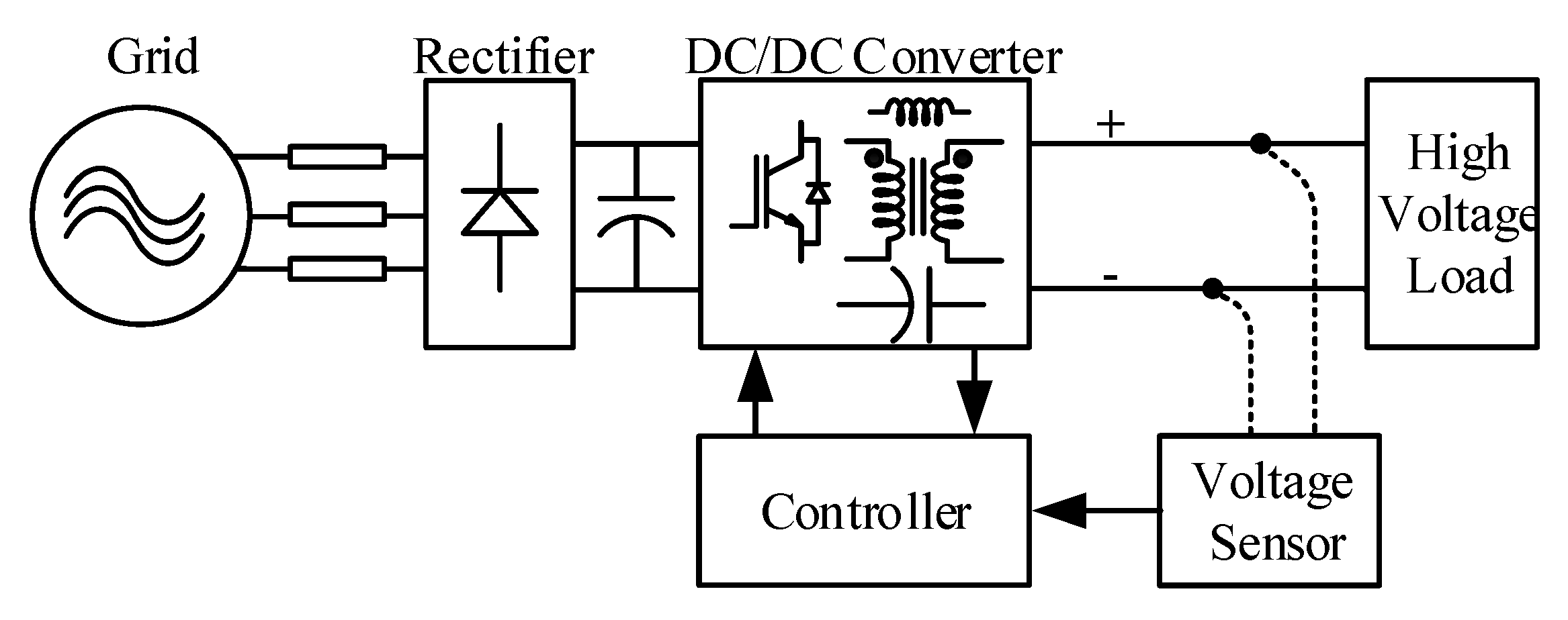
Figure 1. The emerging topology for supplying high voltage direct current (DC) load.
Electronics 09 02066 g001
Figure 2. Control structure of two sensorless voltage controlled current-fed step-up converters. (a) Based on transformer (isolated type); (b) Based on Cockcroft-Walton Voltage Multiplier (CWVM).
Electronics 09 02066 g002
Figure 3. The accurate model of the step-up DC-DC converter based on transformer (isolated type), referred to the the primary side.
Electronics 09 02066 g003
Figure 4. The accurate model of the step-up DC-DC converter based on CWVM.
Electronics 09 02066 g004
Figure 5. Block diagram of the Extended Kalman Filter (EKF). (a) EKF implementation; (b) using EKF for converter control system.
Electronics 09 02066 g005
Figure 6. Simulation results for the ideal CWVM based DC-DC converter. (a) Sampled inductor current; (b) output voltage.
Electronics 09 02066 g006
Figure 7. Simulation results for the non-ideal CWVM based converter. (a) Sampled inductor current; (b) output voltage.
Electronics 09 02066 g007
Figure 8. Simulation results for the ideal isolated type DC-DC converter. (a) Sampled inductor current; (b) output voltage; (c) magnetizing inductor current.
Electronics 09 02066 g008
Figure 9. Simulation results for the non-ideal isolated type DC-DC converter. (a) Sampled inductor current; (b) output voltage; (c) magnetizing inductor current.
Electronics 09 02066 g009
Figure 10. Experimental set-up of the current-fed CWVM based converter.
Electronics 09 02066 g010
Figure 11. Experimental results for the applied gate-source voltage to the Metal Oxide Semiconductor Field Effect Transistors (MOSFETs) (5 V/div). (Duty cycle is 45% and the considered overlap is 1 μs).
Electronics 09 02066 g011
Figure 12. Experimental results for the CWVM based converter. (a) The input voltage of the converter (Vin) (5 V/div); (b) CWVM input voltage (VCW) (20 V/div).
Electronics 09 02066 g012
Figure 13. Experimental results for the CWVM based converter. (a) Sampled inductor current (500 mA/div); (b) output voltage (20 V/div).
Electronics 09 02066 g013
Figure 14. The voltage observer result for output voltage estimation using the experimentally measured inductor current.
Electronics 09 02066 g014
Table 1. Specifications of the CWVM based DC-DC Converter (simulation and laboratory prototype).
ParameterValue
Vin(Input Voltage)12 V
Vout(Output Voltage)50 V
fs(Switching Frequency)50 kHz
L12 mH
RL120 mΩ
L20.5 mH
RL220 mΩ
C1 & C2220 μF
RC1 & RC20.1 Ω
RDS0.1 Ω
RD1 mΩ
VD0.8 V
Table 2. Specifications of the isolated type DC-DC Converter.
ParameterValue
Vin(Input Voltage)12 V
Vout(Output Voltage)50 V
fs(Switching Frequency)40 kHz
Ls650 μH
RLs20 mΩ
Lm650 μH
N1(Primary Winding Number of Turns)31 turns
N2(Secondary Winding Number of Turns)13 turns
RL120 mΩ
RL220 mΩ
Cb470 μF
RCb10 mΩ
Co990 μF
RCo10 mΩ
RDS0.1 Ω
RD1 mΩ
VD0.8 V
Publisher’s Note: MDPI stays neutral with regard to jurisdictional claims in published maps and institutional affiliations.