Review

Wirelessly-Powered Cage Designs for Supporting Long-Term Experiments on Small Freely Behaving Animals in a Large Experimental Arena

1
Department of Electrical Engineering, Incheon National University, Incheon 22012, Korea
2
Department of Electrical and Computer Engineering, North Carolina State University, 890 Oval Dr, Raleigh, NC 27606, USA
*
Author to whom correspondence should be addressed.
Electronics 2020, 9(12), 1999; https://doi.org/10.3390/electronics9121999
Submission received: 22 October 2020 / Revised: 14 November 2020 / Accepted: 18 November 2020 / Published: 25 November 2020
(This article belongs to the Special Issue Wireless Power/Data Transfer, Energy Harvesting System Design)

Abstract

:
In modern implantable medical devices (IMDs), wireless power transmission (WPT) between inside and outside of the animal body is essential to power the IMD. Unlike conventional WPT, which transmits the wireless power only between fixed Tx and Rx coils, the wirelessly-powered cage system can wirelessly power the IMD implanted in a small animal subject while the animal freely moves inside the cage during the experiment. A few wirelessly-powered cage systems have been developed to either directly power the IMD or recharge batteries during the experiment. Since these systems adapted different power carrier frequencies, coil configurations, subject tracking techniques, and wireless powered area, it is important for designers to select suitable wirelessly-powered cage designs, considering the practical limitations in wirelessly powering the IMD, such as power transfer efficiency (PTE), power delivered to load (PDL), closed-loop power control (CLPC), scalability, spatial/angular misalignment, near-field data telemetry, and safety issues against various perturbations during the longitudinal animal experiment. In this article, we review the trend of state-of-the-art wirelessly-powered cage designs and practical considerations of relevant technologies for various IMD applications.

1. Introduction

Implantable medical devices (IMDs) have been developed for behavioral neurosciences which research on small freely moving animal subjects, such as rodents [1,2,3,4,5]. Conventional hardwired IMD in Figure 1a, which is restricting experiments for freely behaving animal subjects [1,2], have been replaced with battery-powered IMDs. However, the battery needs be replaced after 2–4 h animal experiments [3,4], resulting in the interruption for continuous and smooth flow of the experiments, as shown in Figure 1b. When the IMD is fully implanted inside the animal body, the risk for replacing the battery dramatically increases due to the potential infection in the animal body during the surgery.
In an attempt to overcome the limitations imposed by the replacement of battery in IMDs, the wirelessly-powered cage systems have been developed to recharge the batteries without detaching the IMD from the animal during the experiment. However, since these systems are designed to provide the wireless charging in the fixed distance, as shown in Figure 1c, similar to the mobile phone chargers, they are still not suitable for longitudinal animal studies over the span of several days, weeks, or months [5]. Therefore, several concepts of the wirelessly-powered cage have been proposed to extend the wireless coverage and also provide the homogenous power transfer efficiency (PTE) while the small animal is freely behaving inside the cage, as shown in Figure 1d. The key techniques for the wirelessly-powered cage include: (1) the optimized transmitter (Tx) coil design for the extended area; (2) the closed-loop power control (CLPC) for safe wireless power transmission (WPT) [6]; (3) the compensation technique for spatial/angular misalignments of receiver (Rx) coil; (4) the animal tracking technique for the scalability of wireless coverage; and (5) near-field data transmission, while other technologies can also be considered depending on the intended medical applications. Despite the exciting current art, all the requirements of an application involving high-performance or mm-scaled IMDs cannot be addressed by a current existing wirelessly-power cage design. It is important for designers to select suitable wirelessly-powered platforms considering their practical limitations with respect to the IMD design. This review article focuses on the overview of related technologies in recent wirelessly-powered cage platforms including the fundamental principles and practical considerations and provides the guidelines for designers to customize the appropriate wirelessly-powered cages with respect to their IMD applications. The optimized wirelessly-powered cage for the target application based on this article will enable the automated, high throughput, and long-term experiments in a large number of parallel standard cages or in a cage with specific shape for single or multiple animal subjects.
In this article, these key technologies for wirelessly-powered cages are categorized and discussed with the practical design considerations that include the CLPC, coil design/optimization, scalability for wireless coverage, special/angular misalignment, near-field data telemetry, and safety issues. In Section 2, the main blocks for wirelessly-powered cage systems are introduced with the practical considerations related to the key technologies. Section 3 provides the different designs of wirelessly-powered cages with the performance comparison. Section 4 introduces the state-of-the-art wirelessly-powered cages for mm-sized IMDs, followed by a conclusion.

2. Main Blocks for Wirelessly-Powered Cage System

Figure 2 shows a simplified block diagram of the wirelessly-powered cage system and the IMD attached to or implanted in the freely-moving animal subject. The wirelessly-powered cage system typically includes a main controller, a power amplifier (PA), a pair of data Tx/Rx, a Tx coil array, and a position sensor to localize the Rx coil in the IMD. The wireless link for the power and data transmission is established between the Tx coil array and the Rx coil through the skin/air while the PA driving the Tx coil array tuned at the power carrier frequency, fp. The amount of wireless power driven from the PA is typically controlled by the main controller, namely PC or microcontroller unit (MCU), depending on the amount of received power by the Rx. Unlike the WPT system including Tx and Rx coils with fixed distance, the coupling between the Tx and Rx coils in the wirelessly-powered cage is varying due to the movements of the animal subject, resulted in the received power variations. The CLPC, composed of the received data from the IMD, the main controller, and the PA, increases the Tx power in the PA until enough power is delivered to the Rx while it reduces the Tx power when the Rx receives enough power.
The Tx coil array is one of the important design considerations in the wirelessly-powered cage system to provide the high and homogeneous PTE and power delivered to the load (PDL) within the cage. The Tx coil array can be optimized for a designated arena while it also can be extended for a larger area with the modular type design. Although the achievable PTE and PDL by the inductive link are important for the Tx coil array, the homogeneity of the PTE across the cage should also be considered due to the animal subject’s freely movements. In most of the wirelessly-powered cages with the Tx coil array, the position sensor selects the nearest Tx coil among the Tx coil array to the Rx coil. Since only the selected Tx coil will be activated, this position sensing mechanism helps to reduce power loss significantly. Furthermore, each single Tx coil in the modular design of Tx coil array is optimized with the Rx coil to improve the PTE within the entire wirelessly-powered arena. The near-field data telemetry between the Tx and Rx coils can be used to control the IMD, monitor the received power, and/or acquire the biomedical data from the IMD. Even though far-field communication has the advantage of longer data transmission distance, near-field communication is regarded as a more suitable method in terms of power saving in IMDs. Given that the IMD is always located within the wirelessly-powered cage or arena, the coupling between Tx and Rx coils is always enough to deliver both power and data [7]. Here are some practical considerations for different types of wirelessly-powered cage used in the freely-moving animal experiments.

2.1. Coil Design and Optimization

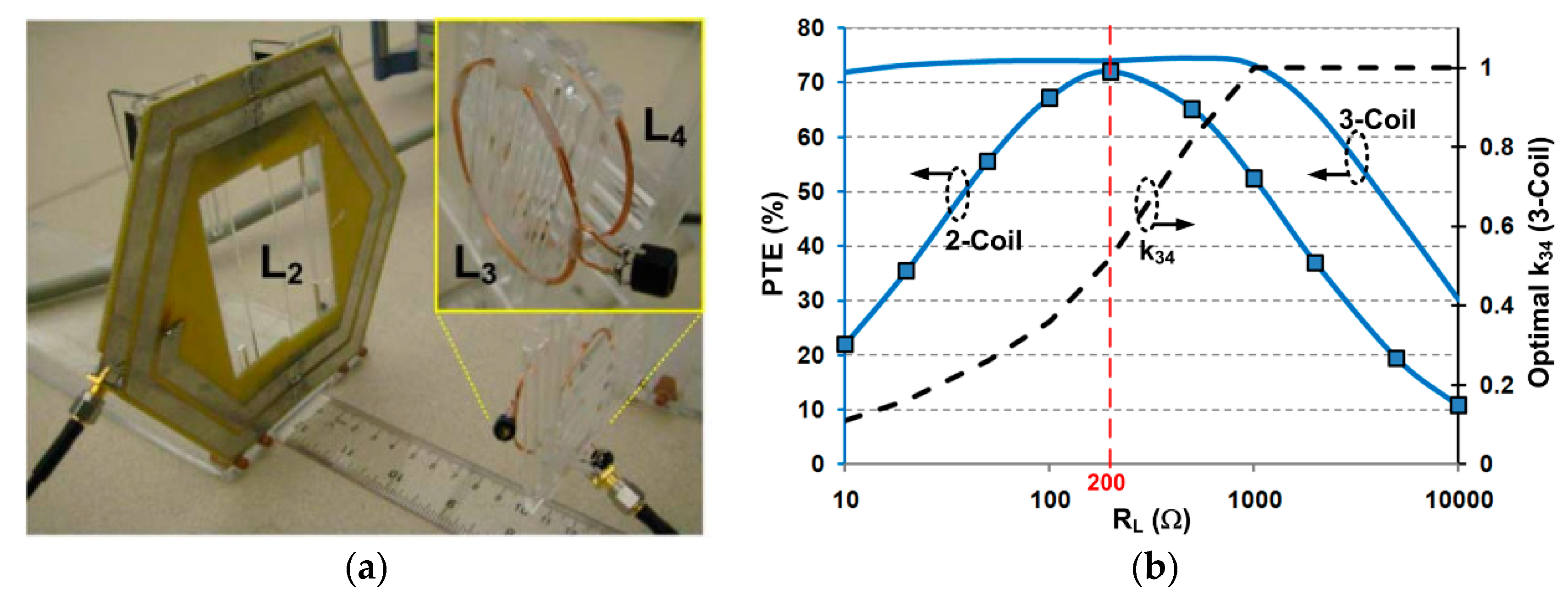
2.1.1. Coil Optimization for Conventional Two-/Three-/Four-Coil Inductive Links

IMDs typically have a tight limitation in their size depending on the applications, resulting in the diameter limitation of Rx coil in the body. In contrast, the Tx coil in the wirelessly-powered cage has more size relaxation in its design. In the inductive link, the coil geometries should be carefully designed to achieve the efficient inductive coupling considering the load and coil separation. Figure 3 shows the physical and electrical configurations of a two-coil inductive link with geometrical parameters used for primary (L1) and secondary (L2) coils, where din is inner diameter of each coil, dout is outer diameter of coils, N is number of turns, and z is the coil separation between L1 and L2 coils. The mutual inductance between Tx and Rx coils (M12) is defined by M 12 = k L 1 L 2 , where k is the coupling coefficient of the two-coil link. M12 shows the ratio of magnetic flux common to both L1 and L2. R1 and R2 are the series resistance of the Tx and Rx coils, respectively. The quality factor (Q) of each coil is defined by Q = ωL/R, where ω = 2πf0 and f0 is the power carrier frequency.
Although the two-coil inductive link has its optimized solution for highest PTE depending on a given set of Q1, Q2, and k12 based on [8], the optimized load resistance, RL,PTE, is sometimes far from the nominal target load resistance, RL, which is predefined in the IMD application. Therefore, the multi-coil solution such as three- or four-coil inductive links has been widely studied to provide the designer with more degrees of freedom to convert RL to RL,PTE and thereby maximize PTE, while they have a potential negative impact on the size-constrained applications. Figure 4 shows the two-, three-, and four-coil inductive links with the lumped circuit model. The PTE of two-, three-, and four-coil inductive links can be calculated based on the basic circuit theory found in [9].
η 2 coil = η 23 = k 23 2 Q 2 Q 3 L 1 + k 23 2 Q 2 Q 3 L · Q 3 L Q L ,
η 3 coil = η 23 η 34 = ( k 23 2 Q 2 Q 3 ) ( k 34 2 Q 3 Q 4 L ) [ ( 1 + k 23 2 Q 2 Q 3 + k 34 2 Q 3 Q 4 L ) ( 1 + k 34 2 Q 3 Q 4 L ) ] · Q 4 L Q L ,
η 4 coil = η 12 · η 23 · η 34 = ( k 12 2 Q 1 Q 2 ) ( k 23 2 Q 2 Q 3 ) ( k 34 2 Q 3 Q 4 L ) [ ( 1 + k 12 2 Q 1 Q 2 ) · ( 1 + k 34 2 Q 3 Q 4 L ) + k 23 2 Q 2 Q 3 ] · [ 1 + k 23 2 Q 2 Q 3 + k 34 2 Q 3 Q 4 L ] Q 4 L Q L
where Q3L and Q4L are the loaded quality factor, Q3L = Q3QL/(Q3 + QL) and Q4L = Q4QL/(Q4 + QL), in which the load quality factor, QL = RL/ωL. Note that the source output resistance, RS, is included in the driver coil resistance. The Equation (2) implies that the three-coil link gives the designers with an additional degree of freedom (k23) to adjust the reflected load onto L2 to be the optimal value, RL,PTE, compared to the two-coil link. The PTE of the three-coil inductive link is related with k23, k34, Q2, Q3, and Q4, for a given load condition. The four-coil link can provide an additional degree of freedom (k12) from the three-coil link for the impedance matching on the source side based on (3). Since the two-, three-, and four-coil inductive links have different strengths and weaknesses in the coupling coefficient (k), PDL, and coupling variations as summarized in Table 1, the designers can select the appropriate inductive link configuration depending on the specifications of the WPT system [9].
The optimization procedures of two-, three-, and four-coil inductive links start with the design constrains imposed by the application and coil fabrication technology. The design constrains in the Rx defines the maximum outer diameter of coils in the IMD, and the coil fabrication technology indicates the minimum line width and line spacing. Depending on the application, the coil separation between L2 and L3 (z23), the nominal load resistance (RL), and the source resistance (Rs) are also determined. In the two-coil optimization procedure, k23Q2Q3 should be maximized to achieve the maximum η2-coil based on (1). The optimum k23, Q2, and Q3 can be derived by the proper outer and inner diameter of Tx coil, inner diameter of Rx coil, and number of turns for Tx and Rx coils at given design constraints [8]. The three-coil link optimization procedure maximizes η23 and Q4 in (2), and additionally adjust k34 in the Rx to provide the maximum PTE, η3-coil. A more detailed flow chart is discussed in [9]. In this optimization procedure, the additional L3 coil in the Rx plays the role of an impedance-matching circuit, which can convert an arbitrary RL to RL,PTE for optimal PTE compared to the conventional two-coil link. In other words, the reflected load on the Tx can be adjustable for maximizing the PTE if the designer can choose the suitable k23 and k34 in the design of a three-coil link. As shown in Figure 5 which shows the exemplar designs of two- and three-coil inductive links, the three-coil link can maintain the maximum PTE by adjusting k34 while the two-coil link only reaches the optimal PTE for a specific RL = 200 Ω [9].
The four-coil link is sometimes very useful especially for large coil distance between the Tx and Rx and the large source impedance, Rs, since it provides the additional degree of freedom on the Tx side. Therefore, the four-coil link is widely implemented in the high carrier frequency applications because Rs in the PA is typically increased in the higher frequency. The four-coil link can tolerate the variations in k23 caused by the coil separation varying and maintain the high PTE by keeping k12 large. The four-coil link optimization maximizes the individual parameters of k23Q2Q3, Q1, Q4, k12 as similar in the two- and three-coil link optimization. Then, the optimal k34 is chosen to provide the maximum PTE as discussed in [9]. The optimization geometries of two-, three-, or four-coil links should satisfy the specific absorption rate (SAR) limit which can be verified by a field solver. If the resulted design cannot satisfy the SAR limit, the designer needs to modify the design constraints and perform the optimization procedure again. The segmented coil design in [10] helps to reduce the average SAR while the loss of the overall link is decreased by using a segmented Tx coil. In Figure 6, the segmented coil shows a more uniform E-field distribution compared to a normal coil with the same geometry, resulting in the reduced peak E-field. Therefore, more Tx power is allowable under the same tissue environment and SAR limit.
Although previous studies provide the optimization of two-, three-, or four-coil inductive link [8,9], they only focus on the optimization procedure for fixed Tx and Rx coils that is not simply applicable for powering large arena in the cage. If the designer uses the large Tx coil around the cage, the overall PTE will significantly drop and show large variations depending on the location of the IMD. Several approaches have been studying to improve the PTE from Tx to Rx coils while maintaining the homogeneity of wireless power distribution. These approaches can be mainly classified into two categories: modular design of coil array, as shown in Figure 7, and resonance-based multi-coil inductive link, as shown in Figure 8 in the following section.

2.1.2. Coil Optimization for Inductive Links Implemented in Wirelessly-Powered Cages

For the abovementioned two categories of inductive link configurations, the optimization method for each category is different. First, we talk about the optimization method for the inductive link incorporating Tx coil array [11,12]. Instead of having a single Tx coil, identical Tx coils are repeated and tiled at the bottom of the cage so that wireless power transmission covers the entire cage arena. One of the Tx coils, which is closest to the Rx, is activated, and together with the Rx coil forms a two-coil inductive link. Therefore, the optimization of the Tx coil and the Rx coil can refer to the optimization procedure of the conventional two-coil inductive link. Furthermore, other strategies in terms of the Tx coil array design are implemented to improve the homogeneous distribution of the electromagnetic (EM) field within the entire cage arena. As shown in Figure 7a, the effective area of a single Tx coil, where most of transmitted power are focalized, is located at the center of the Tx coil and has same distances from the edges of the Tx coil. The PTE drops at the boundaries of the adjacent Tx coils. Multi-layer Tx coil array is typically utilized to provide uniform power transmission over large areas. Instead of fully overlapping, one layer is shifted from the other layer, so that the point of intersection of every three adjacent coils is on the center of the coil in the previous layer, as shown in Figure 7a. With the configuration of multi-layer Tx coil array, the effective areas of the Tx coils cover the entire cage arena. Moreover, the Tx coil array should cover larger area than the cage arena so that the edges of the cage arena are still covered by the multi-layer Tx coil array for homogeneous wireless power transmission.
As shown in Figure 7b, the overall PTE distribution across the multi-layer Tx coil array has variations within ±24% of the average PTE. The higher PTE peaks are resulted from the Tx coils on layer 1, while the lower peaks are associated with the Tx coils in layers 2 and 3. On the one hand, the layer 1 is slightly closer to the Rx coil. On the other hand, the Tx coils in layers 2 and 3 are more overlapped and surrounded by other Tx coils. This condition leads to larger parasitic capacitance and resistance, resulting in the lower Q and PTE. Figure 7c shows the PDL distribution when the Rx is swept within the cage at the height of 70 mm. Thanks to the proposed configuration of multi-layer Tx coil array together with the CLPC mechanism, the PDL can be maintained at 20 mW with fluctuations of less than 2 mW. It should be noticed that one of the main disadvantages in this modular system is that one PA is required for each driving coil in the coil array, resulting in the increased complexity and cost of the Tx design.
The other type of coil optimization is relevant to the inductive link incorporating Tx and/or Rx resonator, for instance the resonance-based four-coil inductive link implemented in the EnerCage-HC system families [13,14]. The key factor in determining the Tx resonator geometries in EnerCage-HC system is the compatibility with dimensions of the standard-sized rodent homecage and the maximum overlap with the Tx coil. Instead of having an array of identical Tx coils tiled at the bottom of the cage, in the EnerCage-HC system, multiple Tx resonators wrap around the cage to provide wireless power coverage of the entire cage (see Figure 8). In this case, optimizing the four-coil inductive link means increasing the minimum PTE within the homecage to ensure PDL is enough to keep the headstage on when the CLPC adjusts the Tx power, as opposed to maximizing PTE in the perfectly aligned regions in traditional coil optimization.
The coupling between loosely coupled Tx and Rx coils is the dominant factor in determining the PTE of the four-coil inductive link. Since the size of the headstage is considerably smaller than the homecage, the effective area of the Rx resonators should be maximized so that more Tx magnetic flux can pass through the Rx resonator, thereby improving the coupling between the Tx and Rx resonators. In [15], the Rx resonator wrap around the headstage, maximizing the area encompassed by the Rx resonator without enlarging the size of the headstage, as shown in Figure 8a. In [14], the largest possible area of the headstage is the diagonal planes of the headstage cube, therefore, the Rx resonators are tilting an angle of 25° compared to the horizontal plane in each four directions of the cubical headstage, as shown in Figure 8b.
Due to the large separation and size difference between the Tx and Rx structures, the Tx and Rx resonators are loosely coupled. Hence, a single target resonance frequency for this system can be set, regardless of the Rx location in the homecage. Additionally, because of the strong coupling among the Tx resonators, only one Tx resonator needs to be finely tuned to match the resonance frequency of the entire Tx structure with the target carrier frequency. Such practical and convenient characteristics are also applicable on the Rx resonators, which are also strongly coupled with each other.
Figure 8c shows the PTE distribution within the 3D volume of the cage. As we can see that while the center area has a weaker magnetic flux density, mutual coupling, and thereby lower PTE, the PTE measured at each height is more uniform, with smaller variations of less than 7%. Although the PTE reduces as the height increases, the deduction of the PTE is slowed, which is mainly credited to the enhancement of EM field by the Tx resonator at the top of the cage. Although the optimization procedures in [13,14] are only dedicated to the specific geometry of the cage, which is difficult to be extended for a large arena, these techniques show high and homogeneous PTE inside the standard geometry of cage. Besides, only one PA is needed, which can significantly simplify the design of the power Tx. Therefore, the designer needs to choose the coil design and optimization procedure whether to adopt a modular coil design or a specific coil design dedicated to a designated area.

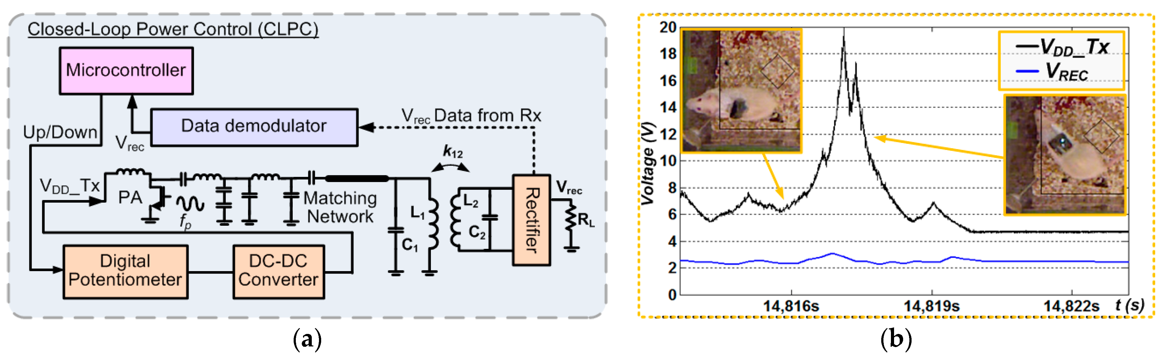
2.2. Closed-Loop Power Control (CLPC)

Compared to the wireless power transmission system between the fixed Tx and Rx coils, as shown in Figure 1c, the Rx coil attached to the animal body continuously moves inside the wirelessly-powered cage resulting in the coupling variation between Tx and Rx coils. In addition, the power consumption in the mobile device is typically not constant for recording or stimulation operation. Therefore, CLPC, which can dynamically compensate for coupling distance and load variations due to animal movements and implant functions, is required to provide enough power for the mobile device [16]. When the mobile device receives more than enough power, the CLPC reduces the Tx power automatically to minimize the power dissipation on the Tx and the EM exposure on the animal subject, resulting in the improvement of wireless link efficiency and ensuring safety.
The CLPC is typically composed of the data communication channel from the Rx to the Tx, the control unit, DC-DC converter, and the PA as shown in the exemplar design of Figure 9a. The rectifier voltage in the Rx, Vrec, is monitored and sent to the Tx through the data communication channel which can be either near-field or far-field data communication. The control unit, such as a microcontroller, in the Tx collects the rectifier information through data demodulator block and determines whether the Rx receives enough power or not. If the Rx is not receiving sufficient power, the microcontroller controls the digital potentiometer to reduce the feedback voltage of DC-DC converter. Then, the DC-DC converter increases the PA supply voltage, VDD_Tx, to increase the amount of transmitted power. Otherwise, the microcontroller adjusts the digital potentiometer to decrease VDD_Tx if the Rx is receiving surplus power. Figure 9b shows the exemplar operation of CLPC in [16]. The CLPC starts to increase the transmitted power by increasing VDD_Tx when the rat moved to low PTE areas or stood up resulting in the weak coupling from the Tx to Rx coils as shown in the inset t = 14,817 s. When the Rx coil was close to the Tx coil located the bottom of the homecage or high PTE areas as shown in the inset t > 14,817 s, the Rx receives more power than necessary resulting in the increase of rectifier voltage, Vrec. Then, the CLPC immediately decreases the VDD_Tx to reduce the transmitted power for the regulation of received Rx power. In the result, the Rx can always receive the constant power from the Tx regardless of any environmental variations during the experiment.

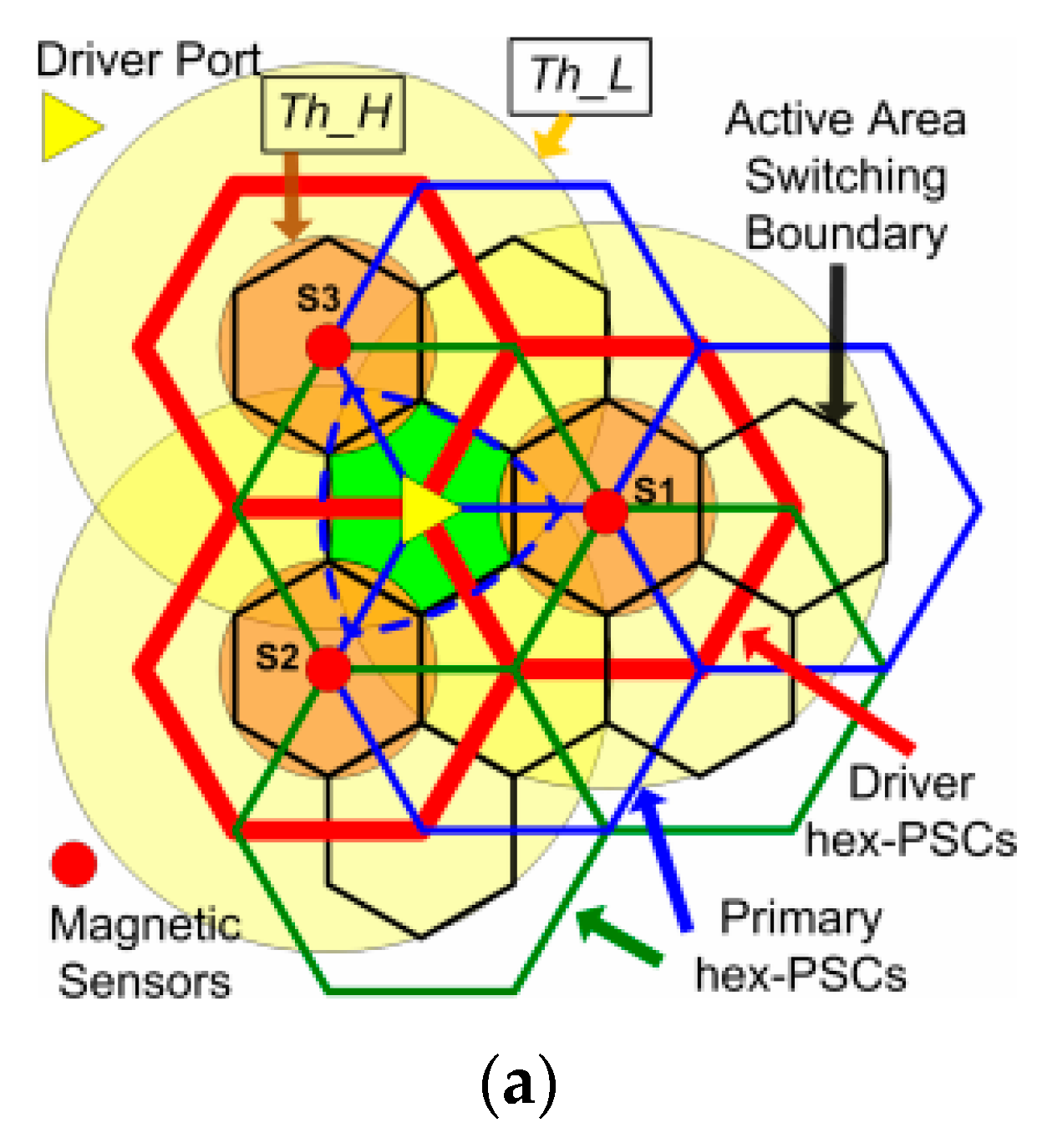
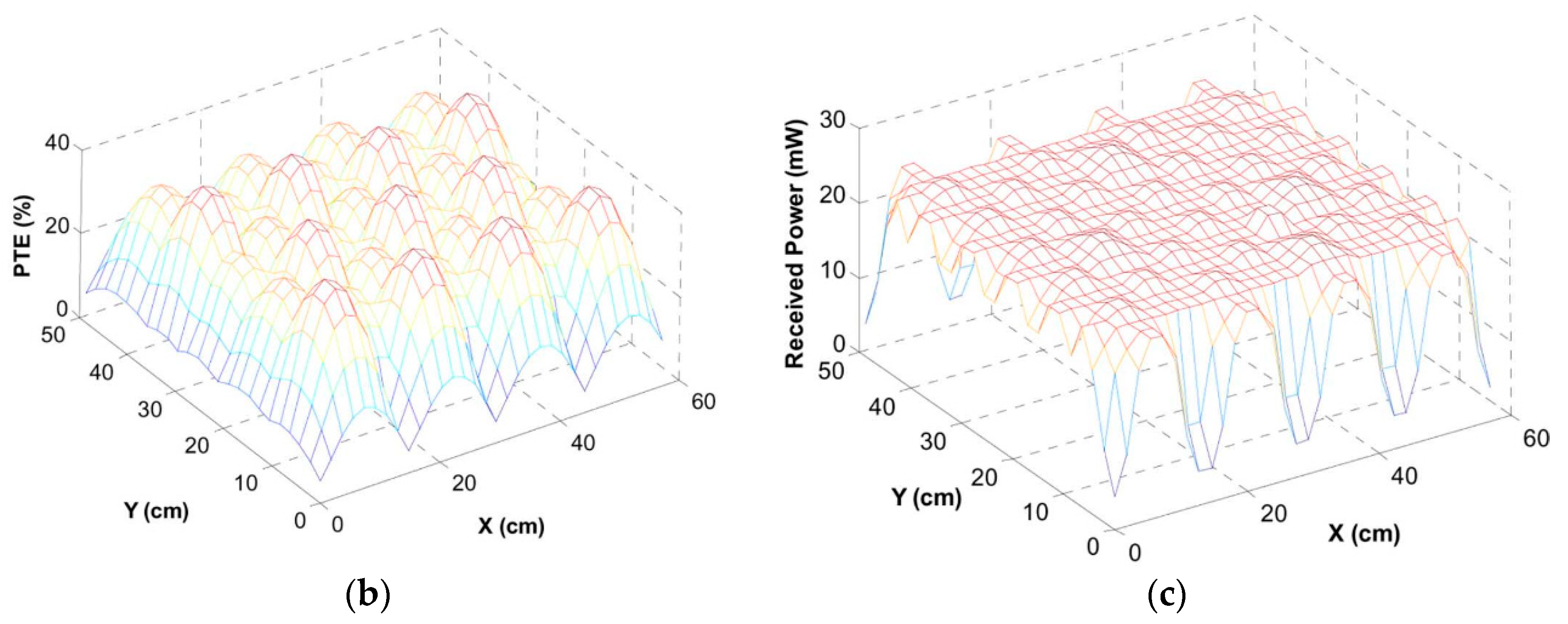
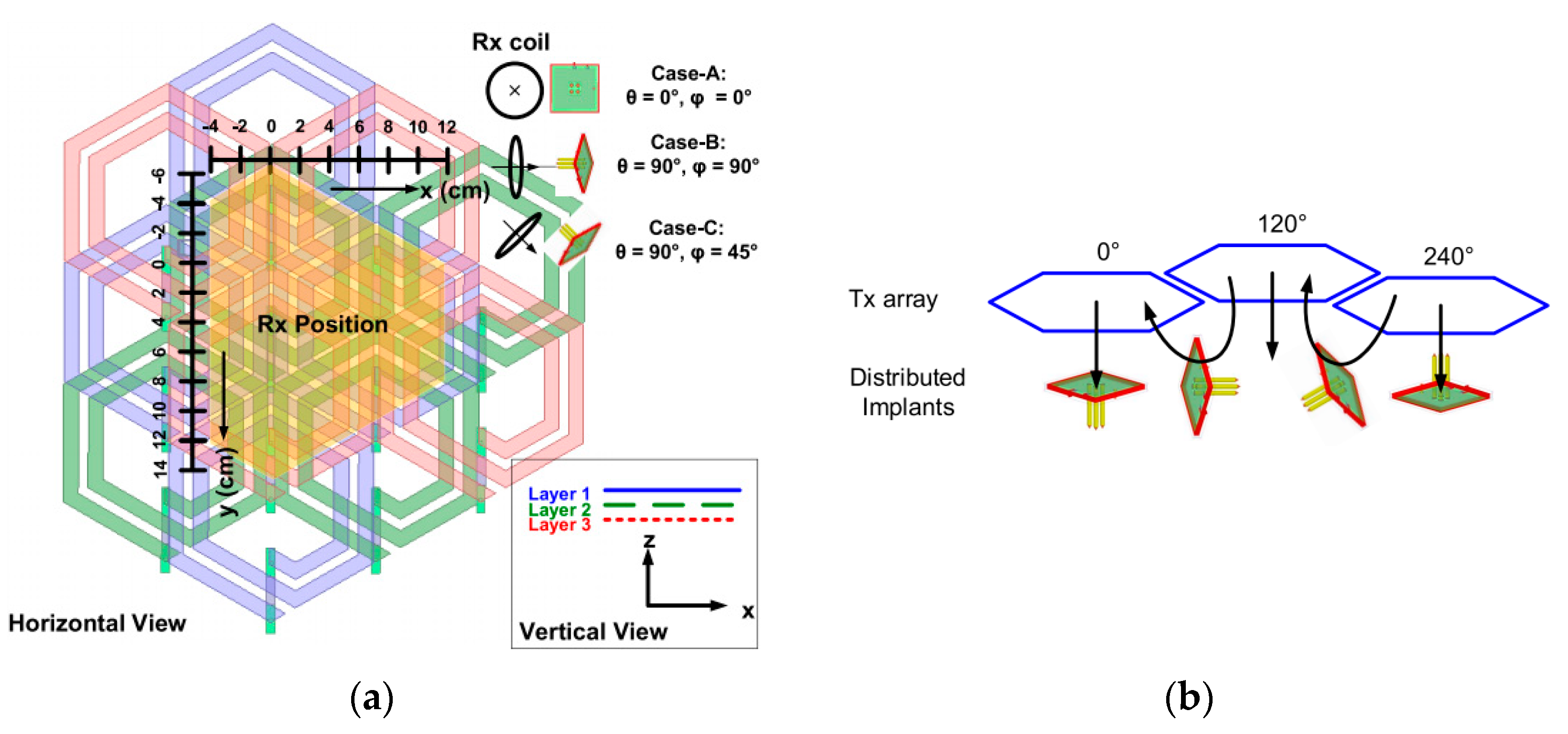
2.3. Scalability for Wireless Coverage

The animal experimental arena can be either a square standard cage or a specific shape with a larger area depending on the experimental purposes. Some wirelessly-powered cages are dedicated to the standard cage [13,16], which have an advantage in terms of compatibility with the standard racks of rodent cages in the animal facilities compared to the modular design for a specific shape. This compatibility is beneficial for longitudinal studies on multiple animals in separate standard cages resulting in the simultaneous and massive data collection from many animal subjects [15]. The modular designs can be easily extended for large area or specific shape [11,17,18] while the optimized wireless cages dedicated to the standard cage are hard to modify the wireless coverage. One of the important considerations for the scalability using the modular coil design is to choose the suitable method for tracking the Rx coil position because the modular coil design needs to select the nearest Tx coil to the Rx coil. If the modular system does not equip the tracking method, all the Tx coils in the array will be driven simultaneously, resulting in significant power loss. In [11], a small permanent magnet is attached to the mobile device, and the wirelessly-powered cage detects the mobile device using three-axis magnetic sensors to select the nearest Tx coil to the freely moving animal subject. The permanent magnet is also utilized in [18] for the Rx coil tracking, where a single Tx coil moves mechanically on XY-rails located at the bottom of the cage. However, in the WPT system, the performance of magnetic sensors might be degraded due to the strong magnetic fields inside the cage, resulting in not sufficient tracking resolution and quality.
The optical animal tracking techniques are studied in [16,19] using an infrared range camera or a Microsoft Kinect®. The Microsoft Kinect includes infrared depth (IR-3D) and red-green-blue (RGB-2D) cameras allowing animal tracking in both bright and dark conditions. Since the optical tracking method can obtain the information about both the Rx coil position and the animal subject behavior at a time, it is more beneficial than the permanent magnet sensing in terms of the additional analysis of animal locomotion and behavior. However, the optical cameras should be installed on the top of the cage with a few tens of centimeters. As such, the lid of the cage should not be closed during the experiment. As an alternative, the resonator-based cage design, which allows for automatic magnetic field localization, obviating the need for a tracking system or switching the coils, are introduced in [13,14,15,17]. In these systems, the multi-resonator coil arrangement around the cage, simply driven by a single LC-tank located at the bottom of the cage, can dynamically focus the magnetic field at the position of Rx coil. However, the parasitic resistance in multi-resonator coils still dissipates power all the time regardless of the Rx coil position, resulting in the additional power loss compared to the switchable modular Tx coil design.

2.4. Spatial and Angular Misalignment between Tx and Rx Coils

Spatial and angular misalignments and distance variation between Tx and Rx coils inside the wirelessly-powered cage happen quite frequently in practice as freely behaving animal subjects walk, sniff around, rear, and climb the walls of the cage. This will result in a significant reduction in the PTE and PDL, which might cause malfunctions in the mobile device which does not equip energy storage. The homogeneity of wireless coverage achieved by the Tx coil array alleviates the spatial misalignment as shown in Section 2.1.2, and the CLPC in Section 2.2 [11,13,16] compensates the reduced power in the Rx against some angular misalignments or distance variations. However, the Rx coil rarely receives the wireless power from the Tx coil with maximum angular misalignment of 90°. Therefore, the designer should consider the worst-case condition in the wirelessly-powered cage. The most common technique to address the angular misalignment with omnidirectional powering is to implement 3D Rx coils in x-, y-, and z-axis, as shown in Figure 10a [20]. The 3D Rx coil is composed of three individual Rx coils followed by each rectifier as shown in Figure 10b. For the nominal condition which angular misalignment is 0°, the Rxz coil mainly receives the power carrier from the Tx coils while Rxx and Rxy coils rarely receive the power. When the 3D Rx coil has large angular misalignments from the Tx coil, the received power in the Rxx or Rxy coil is increased depending on the misalignment axis to compensate the reduced power in the Rxz coil. The 3D Rx coil can also be implemented by using the multiple resonator coils, L3, instead of multiple load coils, L4, as introduced in Figure 11 [14]. As shown in Figure 11b, the multiple resonators are strongly coupled with L4, while the multiple resonators can receive the power against angular misalignment inside the cage. This technique only utilizes one rectifier resulting in the reduced circuit complexity compared to Figure 11b. Since these 3D Rx coils receive the inductive power from each direction, it provides better homogeneous PTE and PDL against the angular misalignments of the mobile device. However, the 3D Rx coil design in the mobile unit increases the volume compared to the conventional single planar Rx coil, resulting in the limited applications for tiny implants inside the animal body.
Instead of the 3D Rx coil, the new Tx coil configurations are studied to provide the homogeneous magnetic field along with x-, y-, and z-axis [21,22]. The proposed architecture in Figure 12a [21] includes three layers of hexagonal planar spiral coil (hex-PSCs) array for homogeneous distribution of the PTE against angular misalignments. The individual Tx coil array generates power carriers with three phases (0°, 120°, 240°) as shown in Figure 12b, and provides both vertical and lateral magnetic fluxes at the same time over the entire powered 3D volume inside the cage. When the Rx coil is aligned with the Tx coil, the Rx coil can receive the power from the vertical magnetic flux. When the Rx coil has the angular misalignment against the Tx coil by 90°, the lateral magnetic flux between the Tx coils mainly provides the power to the Rx, resulting in ~4% PTE improvement compared to the conventional Tx coil array as shown in Figure 12b.
In [22], the omnidirectional powering is achieved by two dipole coils using DQ rotating magnetic field. This technique utilizes the phase differences in two Tx coils, Tx-D, and Tx-Q, and then, generates the rotating magnetic field in the 3D volume as shown in Figure 13. The AC currents in the Tx-D and Tx-Q have same magnitude with 90° phase difference from each other. These two currents generate the transient magnetic field along with x-, y-, and z-directions by rotating the angular frequency from 0 to 2π as partly shown in Figure 13b–d. Then, the crossed dipole Rx coil can still receive the wireless power from a portion of rotating magnetic fields even though it has the maximum 90° angular misalignment from the Tx coils. Although the Rx coil in this system should be designed in the crossed dipole structure with the ferrite material resulting in the limited applications for tiny biomedical implants, the rotating magnetic field technique can be potentially applicable for external portable biomedical devices attached to the animal body.

2.5. Near-Field Data Telemetry

Since the IMD in the wirelessly-powered cage typically monitors different types of biomedical signals recorded from the electrodes and performs stimulation to tissue for the treatment, the data transmission between the mobile device and the wirelessly-powered cage is required to collect the data and to control the device. In terms of the average power dissipation in the recent IMDs, composed of amplifiers, signal conditioning, digitization, processing, and radio frequency (RF) transmission blocks for neural recording application, the traditional far-field data communication blocks dedicate a relatively large portion of the IMD power budget compared to the other functional blocks [7]. Therefore, the near-field communication can be regarded as a more suitable method in terms of power saving in IMDs, considering that the animal subject moves within the wirelessly-powered cage, and the Tx/Rx coils are already implemented for the wireless powering. While there have been many data telemetry techniques are introduced, it is important for the designers to select suitable data telemetry methods, considering the practical limitations of IMD design related to key aspects, such as power budget, silicon area, IMD dimensions, temperature elevation, data bandwidth, sensitivity, reliability (Bit-Error Rate, BER), and robustness against various perturbations [7].

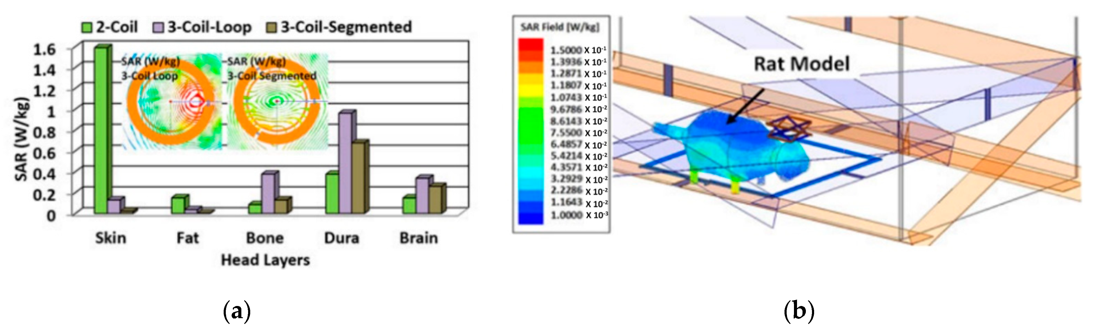
2.6. Specific Absorption Ratio (SAR) and Safety Issues

The transmitted power from the Tx coil should be less than allowable specific absorption rate (SAR) limit, determined by the induced electric field intensity, E, in tissue when exposed to a RF EM field. There are mainly two official international safety standard establishment organizations which have deeply impacted each country for their safety standards. The International Commission on Non-Ionizing Radiation Protection (ICNIRP) has the series exposure guideline for each E-field and H-field. The recent ICNIRP (2010) used the induced E-Field instead of induced current density metric. Meanwhile, the guideline also provided the exposure limits in central nervous system (CNS) tissues of the head and other tissues of the body. Institute of Electrical and Electronics Engineers (IEEE) also provided [23] for exposure standard. Compared with ICNIRP guideline, IEEE standard is widely used in US, Canada, Japan, Korea, etc. It also has basic restriction and reference restriction. When setting protective limits for localized tissue heating due to the difficulty of SAR measurement, the point SAR is mass averaged, in recognition of the thermal diffusion properties of tissue. The averaging mass in ICNIRP is any 10 g of contiguous tissue. IEEE standard specifies a smaller 1 g averaging mass in the shape of a cube. The IEEE limits differ from the ICNIRP guidelines in both the maximum level specified which are 100 W/mm2 for IEEE and 50 W/m2 for ICNIRP, and the frequency at which these peak values reach are 2000 MHz for ICNIRP and 3000 MHz for IEEE [24].
SAR can be calculated by σ|E|2/ρ, where σ and ρ are tissue conductivity and density, respectively. Since the SAR limit allows the less amount of RF exposure for the higher carrier frequency, the designer also needs to select a suitable power carrier frequency for the wirelessly-powered cage system based on the expected maximum power used in the Tx and SAR limit for safety, prior to the PTE or PDL optimization. RF exposure can be evaluated by the simulation using a “phantom”, which emulates the electrical characteristics of the human head, body, or tissue. In [25], the EM simulator, namely HFSS, is utilized to estimate the peak of average SAR values of tissue layers when a mm-size Rx coil implanted in the tissue receives 1.3 mW power. Under different settings of tissue layers, the SAR values with the WPT configuration of a two-coil link, a three-coil link with loop coils, and a three-coil link with segmented coils are compared, as shown in Figure 14a. Figure 14b shows the SAR simulation results with Poynting vectors (the real component of the power density) generated by the EnerCage-HC2 when the Tx power is 1 W for the rat model. In this simulation setup, the rat model is made entirely out of brain tissue with σ = 105 S/m and ρ = 1040 kg/m3, which generates the worst case for SAR simulation [14].
To ensure the safety of EM exposure, SAR can be simulated by various EM simulators, such as HFSS, in the design stage as shown in Figure 14. Additionally, other measures include monitoring the tissue heating using temperature sensor in the IMD [26,27]. Based on the tissue heating information sent from the IMD, the wirelessly-powered cage can limit the amount of transmitted power to conform to the SAR limitation and prevent tissue damage from the abnormal heat generation of the IMD.

3. Designs of Wirelessly-Powered Cage Systems

In this section, we will introduce different designs of wirelessly-powered cage systems, which can be classified into four categories. Based on the design considerations discussed in Section 2, we will discuss the main features of each wirelessly-powered cage design.

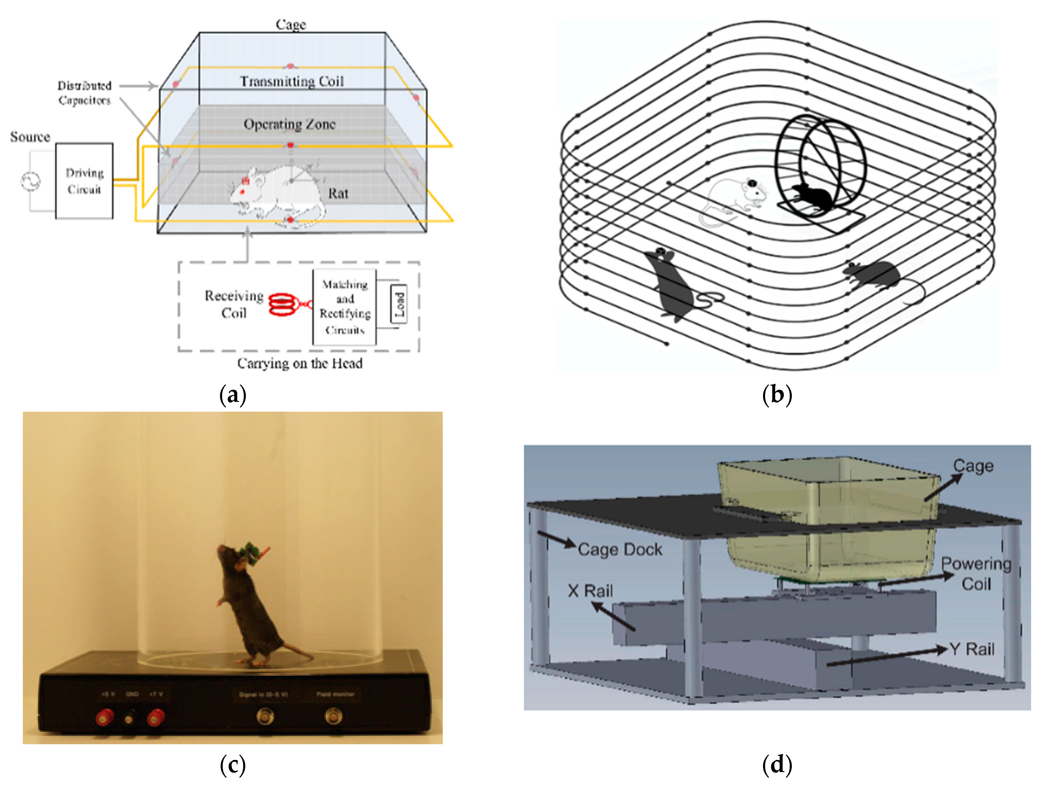
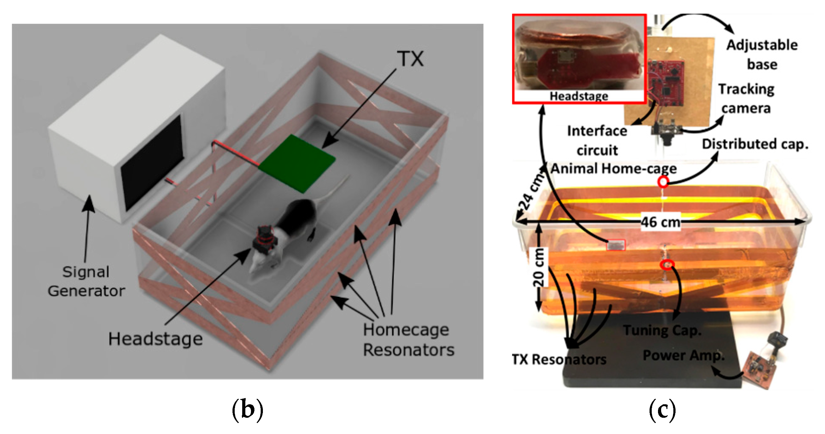
3.1. Wirelessly-Powered Cage Systems with Single Tx Coil Configuration

The single Tx coil configuration can simplify the design of the driver control in the wirelessly-powered cage systems, significantly improving the system robustness. However, the following examples of the wirelessly-powered cage systems with such configuration also suffer from other limitations, which we will discuss in detail [18,28,29,30].
Figure 15a,b show two wirelessly-powered cage designs, each of which a large Tx coil wraps around the cage to enhance the magnetic field within the volume covered by the Tx coil [28,29]. In Figure 15a, the Tx coil comprises two series-connected coaxial rectangular windings, generating an effective operating zone of 40 × 24 × 4 (height) cm [28]. The center of such an operation zone is 7 cm height from the bottom of the cage to cover the vertical movement of the mobile device while the animal is walking and standing. A π-capacitor matching circuit, which matches the Rx coil to the load, is also designed to ensure the wireless power delivery maintaining at the maximum PDL condition. In Figure 15b, the Tx coil completely encompasses the area in which the animals can roam freely, resulting in an effective space of 40 × 40 × 20 (height) cm3 [29]. These two designs can improve the WPT resilience to lateral and vertical misalignments between the Tx and Rx coils. However, the angular misalignments still can negatively impact the PTE of the inductive link. Moreover, due to huge size difference, the pair of Tx and Rx coils is away from their optimal size matching, resulting in the low PTE of these two designs. For a larger experimental arena, the size of the Tx coil will be enlarged accordingly, which will aggravate the coil size mismatch and then the PTE reduction. For the designs in Figure 15a,b, the Tx coil covers the 3D volume of the experimental arena, which can ensure the strength of the magnetic field within the covered volume.
For the wirelessly-powered cage design shown in Figure 15c, the Tx coil is located underneath the circular mouse cage with a diameter of 8 inches, and the power Rx is a 15 mm-long, 2 mm-diameter solenoid coil wrapping around a copper ferrite core [30]. The coil size mismatch is eased in this design, at the cost of smaller wirelessly-powered arena, compared to the designs in Figure 15a,b. The Rx coil continuously receivers a large amount of power of 2 W over distances of several centimeters within the cage. Given that the inductive link is non-optimal, it is challenging to ensure the wireless power transmission safety by not overcoming the SAR limitation in the case of strong power delivery. In this wirelessly-powered cage system, the Tx coil also needs to cover the bottom area of the circular mouse cage. Such a configuration is also not conductive for the system scalability.
Compared to the abovementioned wirelessly-powered cage designs which suffer from the size mismatch between the Tx and Rx coils, the wirelessly-powered cage in Figure 15d does not have this issue [18]. The coils in the inductive link are geomecally optimized. Besides, the optimum alignment between the Tx and Rx coils is also achieved. In Figure 15d, the IRPower system uses a servo-controlled Tx coil moving under the cage on the X and Y rails. A permanent magnet in the mobile device and an array of magnetic sensors placed around the Tx coil form the animal tracking system. Given the real-time optimized size and optimized alignment of the Tx and Rx coils, the PTE of this inductive link design is high. The IRPower system in Figure 15d also features a CLPC, which compensates the PDL variations by adjusting the amount of power transmitted into the Tx coil. However, the mechanical setup of and X and Y rails enlarges the size of the IRPower system, making it incompatible with the standard racks of rodent cages in animal facilities. For high throughput experiments, a large number of cages can be located in standard racks in animal research facilities without occupying precious laboratory space. In addition, with the Tx coil underneath the cage, the systems in Figure 15c,d will have the dramatic reduction in the magnetic field strength and then the PTE, as the distance between the Tx and Rx coil increases. Table 2 compares the features of the abovementioned systems.

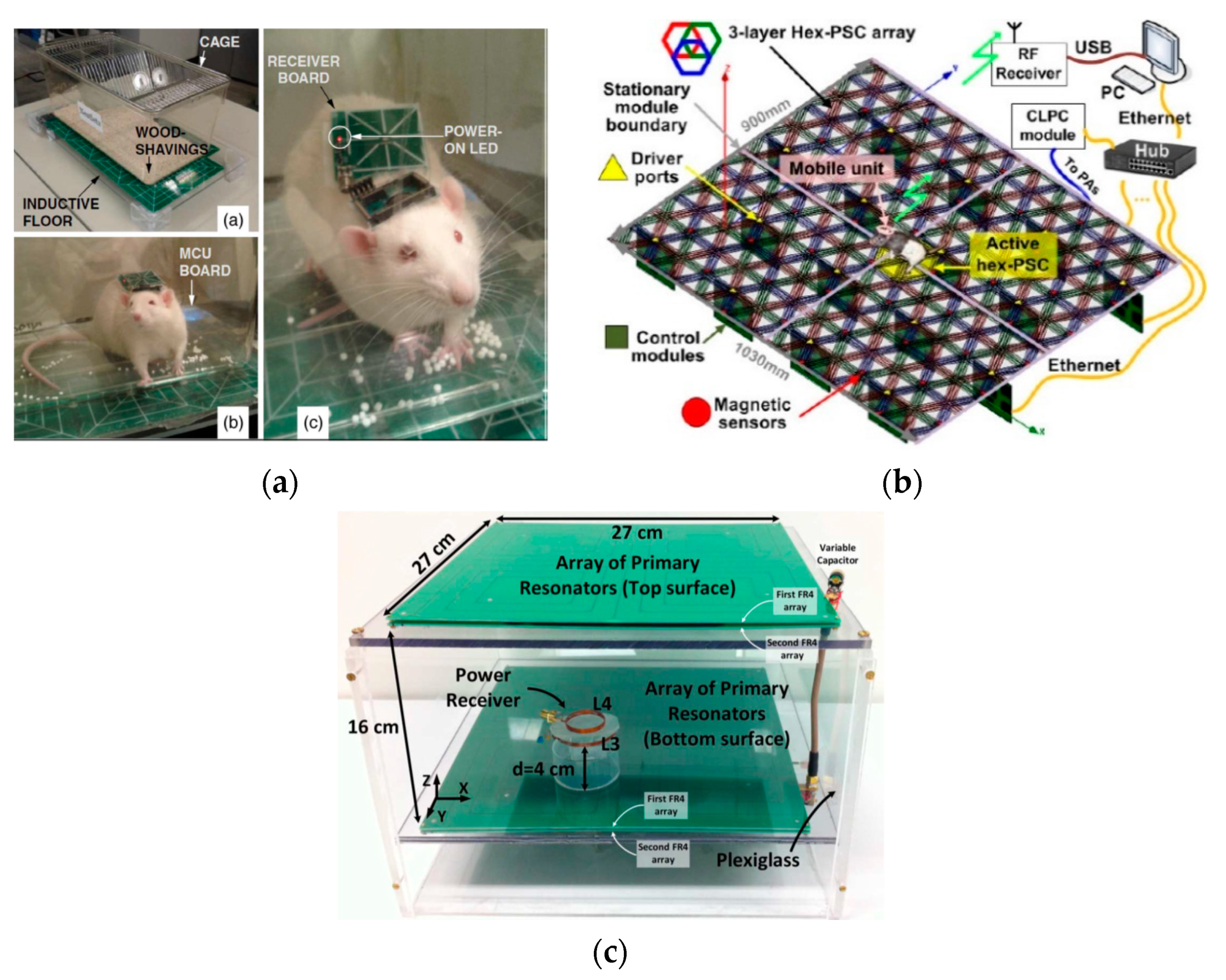
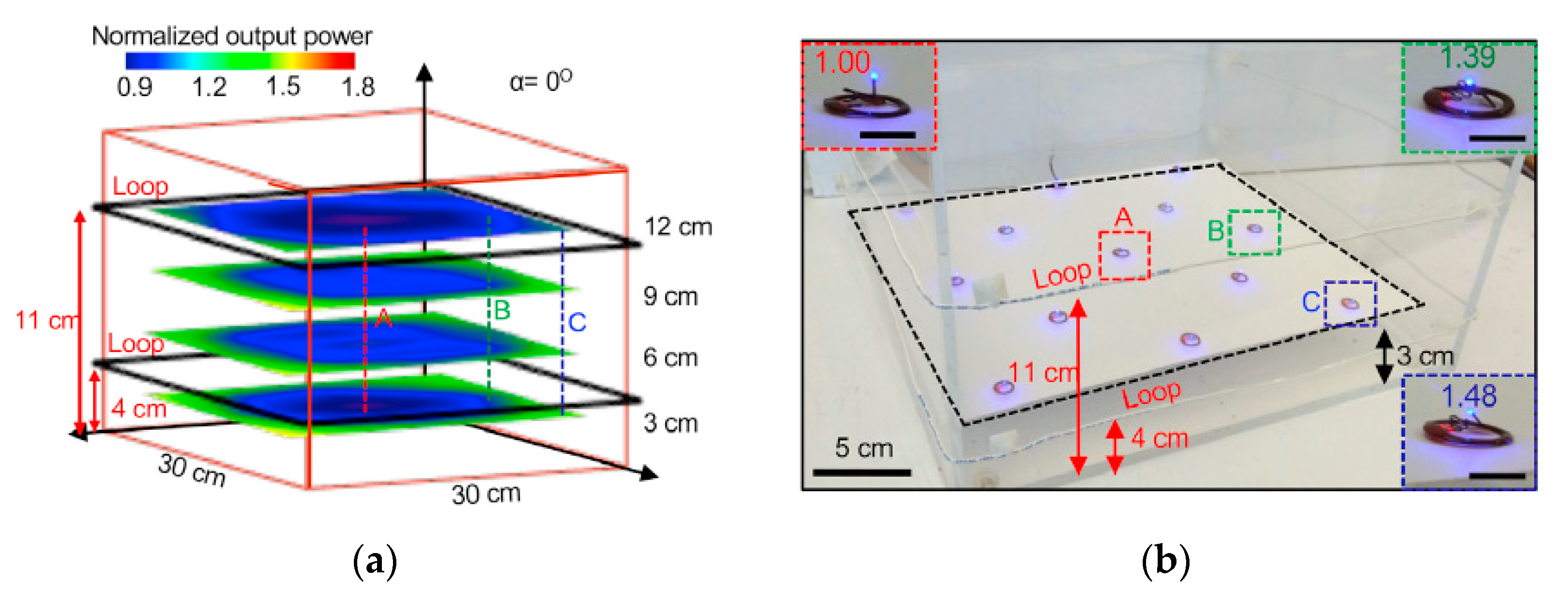
3.2. Wirelessly-Powered Cage Systems with a Scalable Tx Coil Array

With the configuration of the scalable Tx coil array, the wirelessly-powered cage systems introduced in this section have scalable designs [11,17,31]. Each Tx coil in the array has its optimum diameter matched with the Rx coil at a given Rx-Tx separation distance. Within the array, the Tx coil closest to the animal, which is often in the best position to power the mobile unit, is activated. Several different methods have been used to dynamically and automatically activate the Tx coil that is in the optimum alignment with the Rx coil.
The inductive link configuration in Figure 16a includes a single Rx coil embedded in the mobile device and two overlapping arrays of planar Tx coils placed at the bottom of the cage [31]. Every four coils are connected to a single driver module. The 50% overlap in both X and Y directions eliminates dead spots on the power transmission side. Rx tracking is performed by the impedance tracking technique. Particularly, the proximity of the Rx coil will induce a reflected impedance adding onto the Tx coil, causing a reduction in the current drawn from the driver. The Tx power controller detects the impedance variation of each Tx coil by sensing its supply current variation so that the Tx coil closest to the Rx can be identified as the one with supply current reduction.
In Figure 16b, the wirelessly-power cage system includes a resonance-based inductive link with its configuration adjustable [11]. The stationary unit includes a three-layer array of overlapping hex-PSCs that tile the floor of the experimental arena, Tx coils on the third layer driven by PAs and Tx resonators on the first and second layers. The Tx coil can directly link to the mobile unit by forming a three-coil inductive link if the nearest to the Rx is a Tx coil. Otherwise, a four-coil inductive link will be formed if a Tx resonator is closest to the Rx. The animal location tracking is performed via an array of magnetic sensors under the stationary unit and a magnetic tracer in the mobile device. This system is equipped with CLPC, which can enhance the robustness of the wireless power delivery against the Tx-Rx distance variation.
Figure 16c shows another wirelessly-powered cage design based on a 13.56 MHz resonance-based four-coil inductive link [17]. The power Tx includes a Tx coil powered by a PA and two arrays of Tx resonators connected in parallel and tiled at the top and bottom surfaces of the chamber to form uniform wireless power distribution in 3D. The top and bottom resonator arrays have more or less contribution to the power transmission, depending on the location of the mobile device in the z-direction. The distance between the surfaces is set for ensuring almost constant power delivery to the mobile device in the z-direction. Such an arrangement also can improve the system tolerance to angular misalignments, as the Tx resonators at two surfaces will contribute to directing the EM filed towards the mobile device. The Tx resonator array configuration features the natural power localization mechanism that the Tx resonators located directly below and above the mobile device will be automatically activated. Without the requirements of Rx location detection and Tx coil switching, the system implementation can be significantly simplified. However, placing a resonator array on the top surface of the cage limits access to the animals and blocks the field of view of video recording for analyzing animal behavior.
In sum, the abovementioned wirelessly-powered cage systems feature the modular and scalable architecture, which allows for experimental arenas with arbitrary shapes and dimensions. While the Tx includes multiple coils, these systems can still minimize the power interferences as only one Tx coil is activated at a time. Table 3 compares the features of the abovementioned systems.

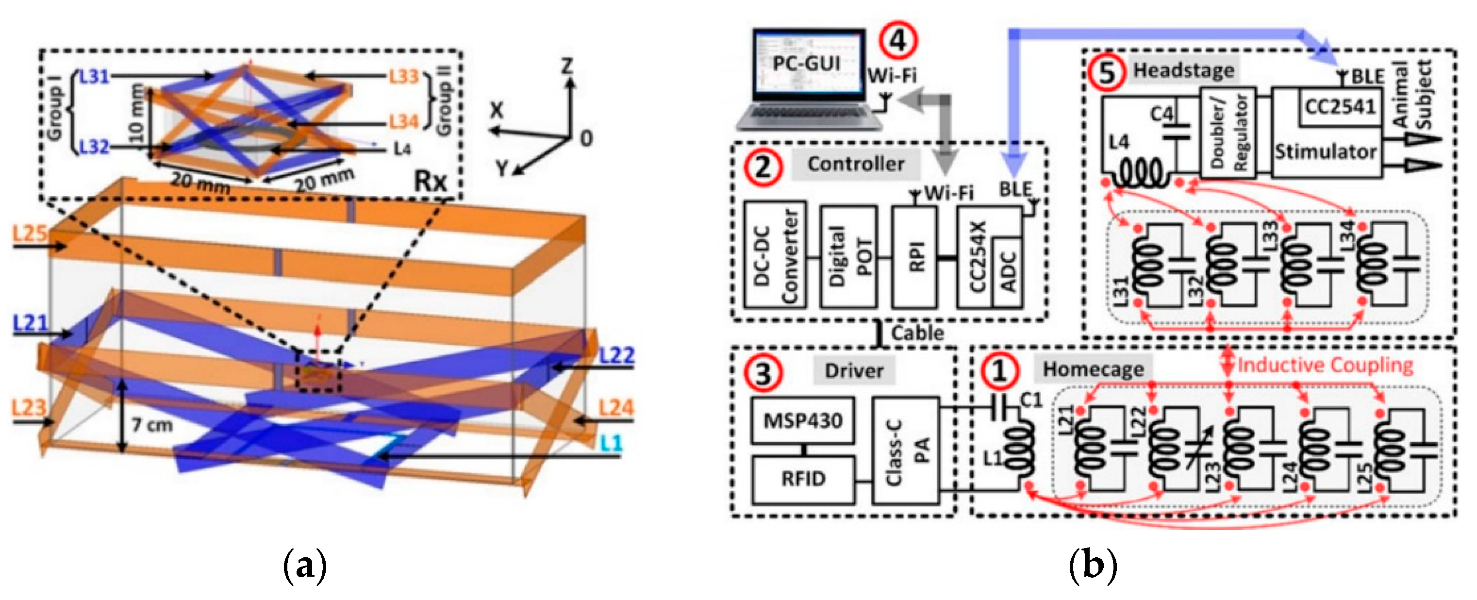
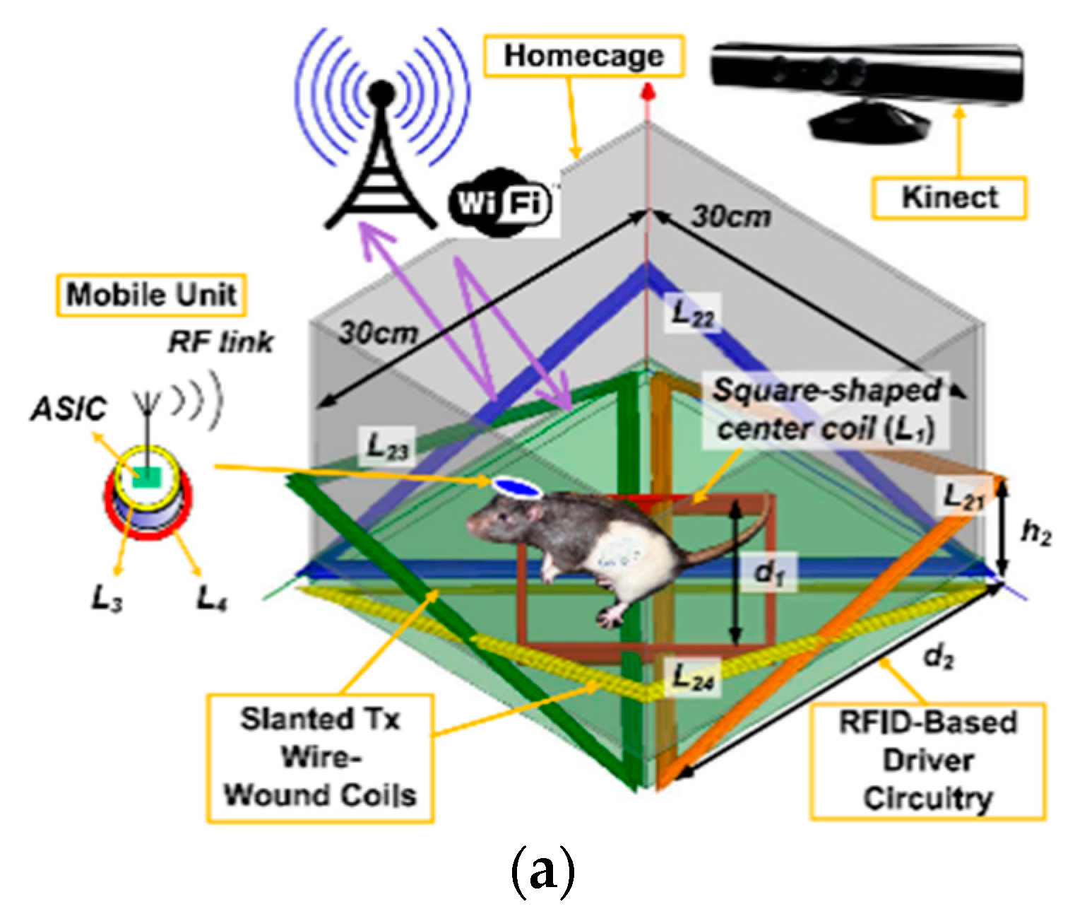
3.3. Wirelessly-Powered Cage Systems with Slanted Tx Resonators

The wirelessly-powered cage systems introduced in this section have multiple slanted Tx resonators wrapping around the cage [13,16,32,33]. The slanted Tx resonators help bend and direct the magnetic flux towards the Rx coil. Such a configuration can improve the system tolerance to angular misalignments. Additionally, the geometry of the Tx and Rx coils are optimized and matched, which is beneficial to improve PTE.
The wirelessly-powered cage system, shown in Figure 17a, is built based on a resonance-based inductive link whose configuration is adjustable [16]. The stationary unit includes one square-shaped central Tx coil at the bottom of the cage and four triangular-shaped slanted Tx resonators on the corners of the cage. The Tx coil can directly form a three-coil inductive link with the coils in the mobile device when the animal moves to the center of the cage, or form a four-coil inductive link with one Tx resonator when the mobile device is at a corner of the cage. The position of the mobile device is tracked in real-time by a Microsoft Kinect installed above the cage. Depending on the recorded position information, the stationary unit will either deactivate all Tx resonators or activate the Tx resonator closest to the mobile device by shorting this Tx resonator with a resonant capacitor for forming an LC-tank with a high quality-factor. However, installing the Microsoft Kinect will enlarge the experimental volume needed for the entire system setup, making the system not compatible to the racks of standard-sized rodent cages.
In Figure 8a, the wirelessly-powered cage system, named EnerCage-HC, includes four-coil inductive link built around a standard-sized rodent cage [13]. The inductive link has a square-shaped Tx coil attached at the center and bottom of the cage and four Tx resonators wrapping around the cage at different heights/orientations, and planar Rx resonator and Rx coil in the mobile device. The slanted Tx resonators, which direct the magnetic field to the mobile device, together with the CLPC can support sufficient and constant PDL up to 80-degree rotation. In Figure 17b,c, two similar wireless cage designs are presented [32,33]. In the wirelessly-powered cage system, shown in Figure 17b, two more Tx resonators, wrapping around the bottom and top rim of the cage, are added to enhance the homogenous distribution of the transmitted power in the z-direction [32]. The Tx coil consists of multiple identical spiral coils connected in series. However, the Tx coil located at the top of the cage may block the line of view of the camera. The wireless cage design, shown in Figure 17c, has a similar Tx resonator configuration [33]. The Tx coil is formed by three identical coils connected in parallel and tiled at the bottom of the cage to make the transmitted power more evenly distributed in 3D.
Thanks to the slanted Tx resonators, the abovementioned wirelessly-powered cage systems show improved robustness to the angular misalignment. Additionally, the Tx coil configuration makes the magnetic field more evenly distributed in the 3D volume of the cage, and the required number of PAs is reduced to only one. For the abovementioned four designs, there is no need for Tx resonator switching, significantly reducing the design complexity, and they feature the compatibility to the standard racks. However, the abovementioned wirelessly-powered cage designs are not scalable. The size of the Tx resonators increases as the cage side increases, which will weaken the advantage of promoting EM uniform distribution. Table 4 compares the features of the abovementioned systems.

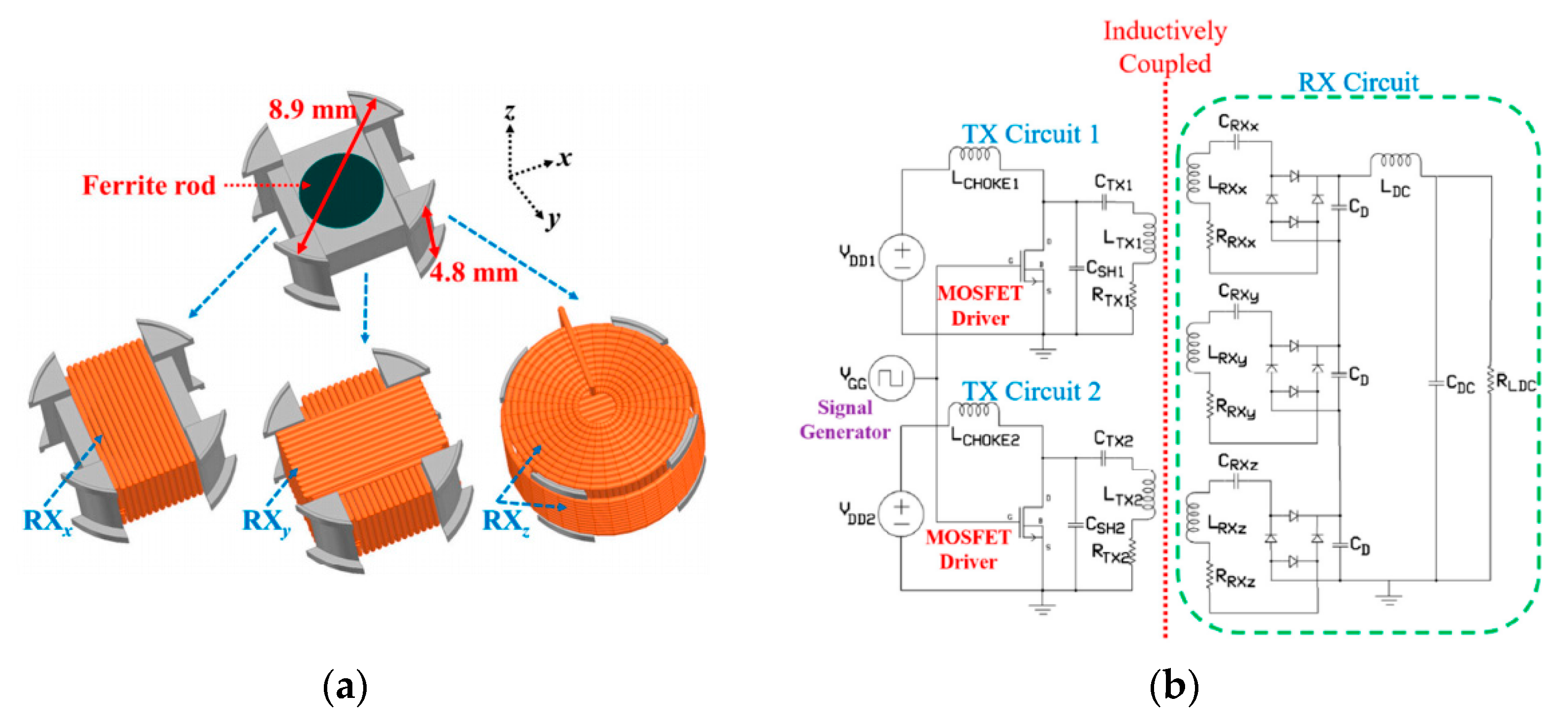
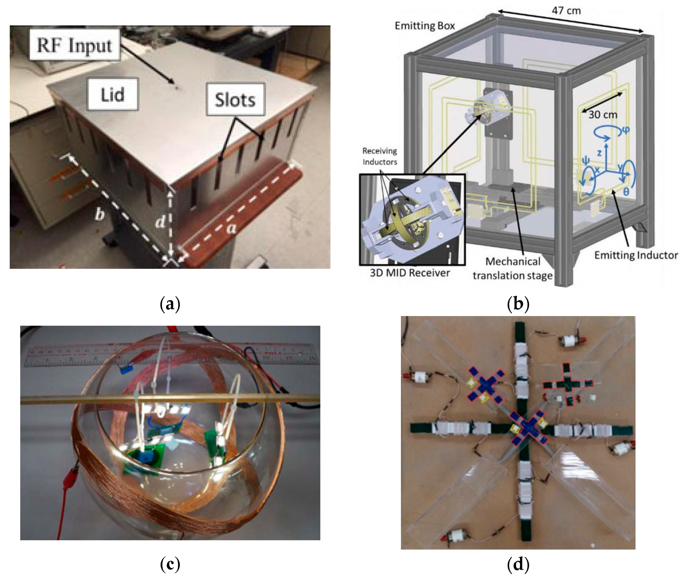
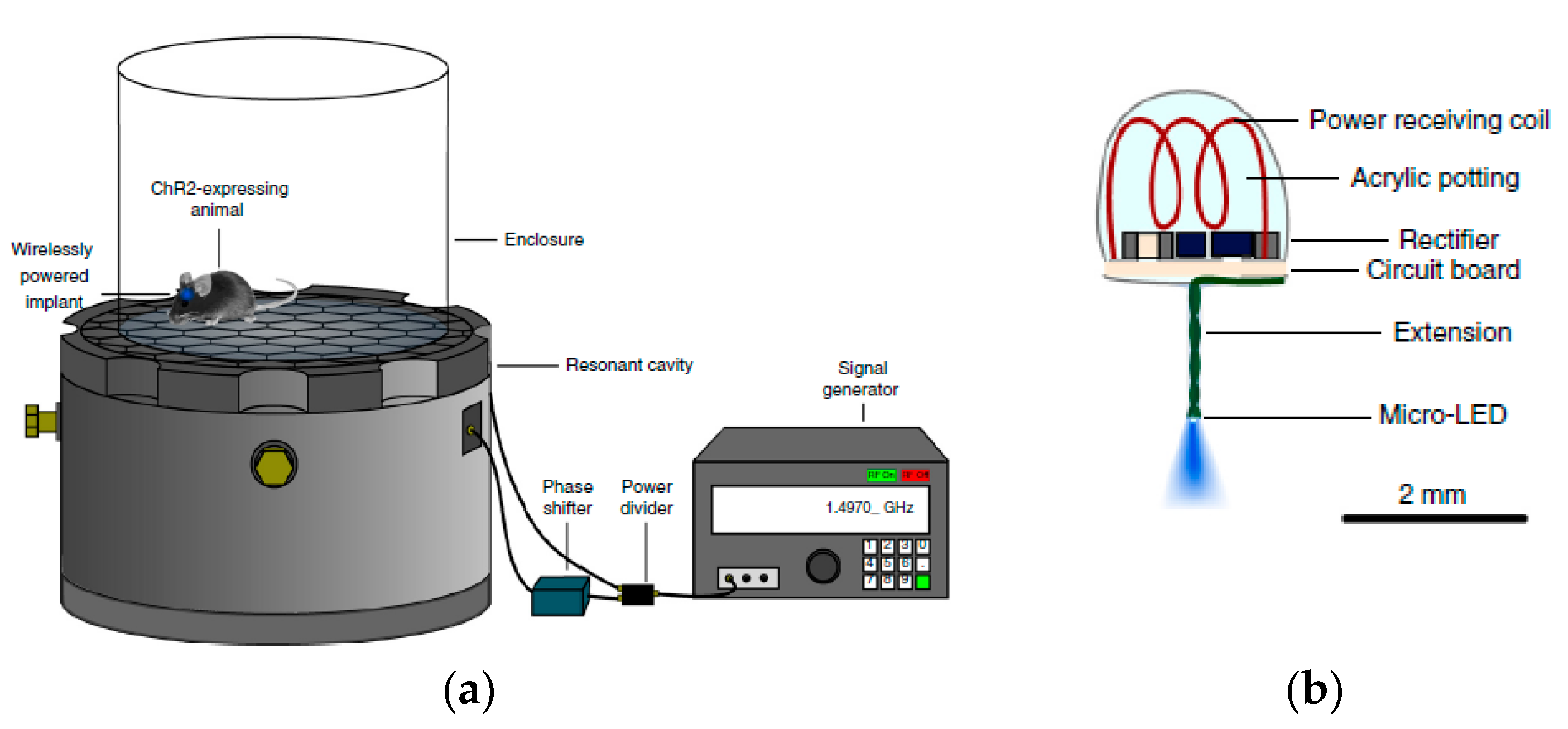
3.4. Wirelessly-Powered Cage Systems for Omnidirectional Power Transmission

In the experiments involving small freely-moving animals, such as rodents, the horizontal, distance, and/or angular misalignments between the power Tx and Rx components may frequently happen due to the animal’s free movements. The misalignments will result in a significant reduction in the PTE and the PDL. In this section, we will introduce several omnidirectional power transmission solutions that can address robust wireless power delivery in the presence of any position and/or orientation variations of the Rx device.
One omnidirectional power transmission solution is a cavity resonator-based wireless cage design, as shown in Figure 18a [34]. On the power Tx side, the H-field produced is rotational around the center of the cavity. The amplitude of the H-field increases radially from the center to the periphery and is not a function of height. On the Rx side, the implantable device has two Rx coils oriented perpendicular to each other. This placement of the two Rx coils can address the device orientation insensitivity within two planes. To achieve truly omnidirectional powering, a third Rx coil oriented perpendicular to the first two Rx coils should be added. Even then, there are still five WPT blind spots, namely the center and four corners of the cavity, where the H-field is very weak.
For the wirelessly-power cage system, shown in Figure 11, we call it EnerCage-HC2 system [14]. Based on the EnerCage-HC system shown in Figure 8a, the fifth Tx resonator is added at the top rim of the homecage to enhance the magnetic flux density at top of the cage. More importantly, the Rx resonators in the EnerCage-HC2 system encompass four diagonal planes of the mobile device. Such a novel Rx coil arrangement directs the transmitted EM field, which is already homogenized by the Tx resonators, towards the Rx coil at the bottom of the mobile device at any arbitrary orientations. Together with CLPC, the inductive link achieves omnidirectional power delivery to the mobile device, irrespective of the subject’s location or head orientation. When the mobile device is 90° rotated while locating along the center lines of the homecage, the magnetic fields passing through the two Rx resonators are bent in the opposite direction and cancel with each other. In this case, little magnetic field can pass through the Rx coil, resulting in PTE drop. It should be noted that the probability of this case happening is quite low in practice. Therefore, we add a small supercapacitor following the rectifier in the mobile device to prevent any sudden drop in the supply voltage.
In addition to the EnerCage-HC2 system, there are three other inductive link configurations that have been proposed to address omnidirectional wireless powering [22,35,36]. One possible coil configuration is a set of triple orthogonal Rx coils together with a single Tx coil. For achieving higher uniformity of magnetic flux, a pair of Tx coils facing each other can be used instead of a single Tx coil. On the Rx side, each Rx coil is followed by an AC-DC converter, such as a rectifier. The three rectifiers can be connected in series or in parallel to drive their common load. In the series connection scenario, the three DC output voltages of the rectifiers are stacked for providing supply voltage for the load. With the parallel connection scheme, the highest Rx coil voltage is automatically delivered to the load. In Figure 18b, two pairs of Tx coils facing each other are attached to the vertical sides of the cage and driven by their own class-D PA simultaneously [35]. On the Rx side, three coils are placed at 90° from each other, which can make the system insensitive to angular misalignments. However, the Tx coil configuration causes two “cold corners” formed by opposite magnetic fields and two “hot corners” formed by constructive magnetic fields in the cage. In the “cold corners”, the triple orthogonal Rx coils still cannot ensure omnidirectional powering. Besides, the Rx coils block the access to the electronics inside the mobile device, making it difficult to repair or to have electrode feed-through.
The triple orthogonal Tx coils together with a single Rx coil is another coil configuration offering the omnidirectional powering. If the three Tx coils are driven by the same current, a constant magnetic field in a fixed direction will be generated. For omnidirectional powering, the three Tx coil currents should be driven appropriately different from each other in order to generate a rotating magnetic field. To achieve this objective, there are three possible modulation methods in general: (1) phase-domain modulation (PDM); (2) amplitude-domain modulation (ADM); and (3) frequency-domain modulation (FDM). Given the simplicity of implementing system control, the PDM method is widely used. In Figure 18c, the PDM method is used. More specifically, the three Tx coils excited with three-phase currents with a peak magnitude of 250 mA and 120° displacement are wound on the outer surface of a glass bowl [36]. The magnetic field vectors rotate periodically in all directions. Three loads hung inside the glass bowl with the Rx coil facing in different directions. Each load consists of a planar Rx coil, a rectifier, and four LEDs. It can be seen that the LEDs in all three loads are on, confirming the omnidirectional nature of the wireless power transmission.
The third viable coil configuration offering omnidirectional powering is the double orthogonal Tx coils together with double orthogonal Rx coils. The two orthogonal Tx coils should be driven by two nonidentical currents to form a rotating magnetic field. Figure 18d shows an example of such a coil configuration [22]. Instead of using loop coils, both the Tx and Rx coil, operating at 280 kHz, have crossed-dipole coil structure. The crossed-dipole Tx and Rx coils are composed of a dual set of two orthogonal coils, wire-wounded around ferromagnetic cores. The currents of the two Tx coils have the same magnitude with a 90° phase difference from each other in order to generate a rotating magnetic field. The magnetic field produced can always pass through the crossed-dipole Rx coils at any orientations, to allow for the omnidirectional power receiving. Additionally, the physical dimensions of Tx and Rx are reduced from volume to plane, which is crucial for practical applications, where volumetric coil structure is highly prohibited. Table 5 compares the features of the abovementioned systems for omnidirectional power transmission.

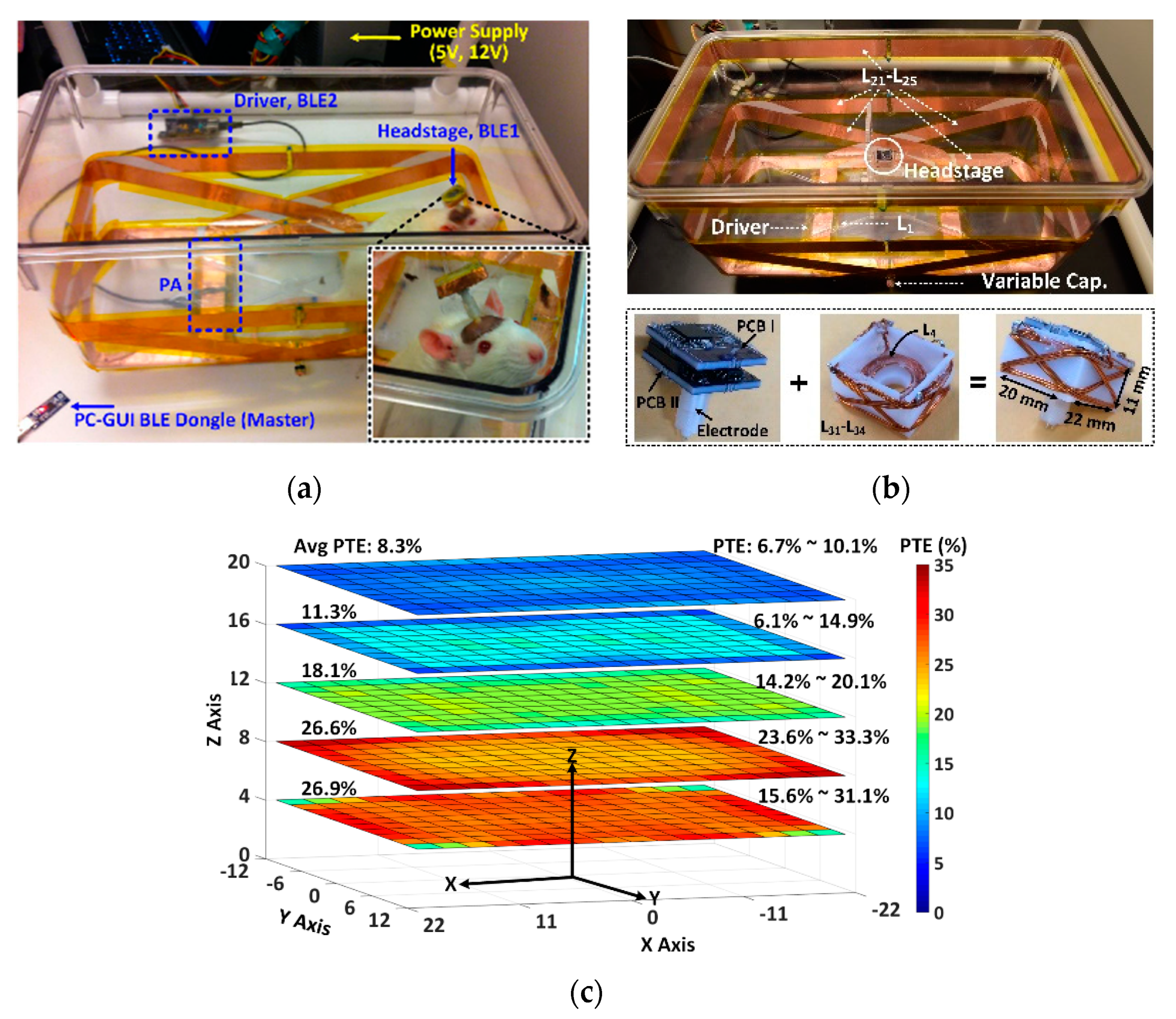
4. Designs of Wirelessly-Powered Cage for mm-Sized Implants

Instead of a single, large, and centralized mobile device [37,38], distributed neural interfaces made of a large number of tiny implants are poised to play a key role in future brain-computer interfaces (BCI) because of their less damage to the surrounding tissue. However, it is challenging to wirelessly operate the tiny implants in a cage. As a result of the significant size difference, the coupling between the Tx and Rx coils is quite weak. The optimal operating frequency for a mm-sized coil to maximize its quality factor is within several tens to hundreds of megahertz range. At such high operating frequencies, it also increases the risk of unsafe exposure to EM radiation and interference, which, in turn, imposes new challenges on SAR compliance. The misalignments caused by free movements of the animal subject and/or the arbitrary placement of the tiny implants, which combine with the other challenges, make it challenging to maintain sufficient power delivery to the tiny implants within a cage. Thus, it is important to develop WPT systems that can overcome these challenges.
A wireless cage based on the resonant cavity was introduced in [39] to power and control tiny implanted devices. An aluminum resonant cavity, which has 21 cm diameter and 15 cm height with a surface lattice of hexagons (2.5 cm diameter), is utilized to couple EM energy with 1.5 GHz carrier frequency to the tissue of a mouse as shown in Figure 19a. Compared to the conventional inductive power transfer system through direct coupling between two coils, the energy in this system is confined to the mouse placed on the grid due to the resonance excitation of the limited EM field pattern. This system can provide self-tracking wireless power to the tiny implant within the mouse resulting in no needs of tracking algorithms over the experimental area. Figure 19b shows a schematic of wireless implant for optogenetic stimulation, designed in the size of 10~25 mm3. This light-emitting implants can receive 5.6~15.7 mW with 3.2 W of averaged input power. Although the wireless operation in RF bands are typically susceptible to signal reflection, interference, and absorption by obstructions, the proposed system in [39] has been successfully demonstrated by behavioral testing environments and has shown the possibility of using RF bands for wireless cage applications.
EM WPT at high frequency in the GHz range facilitate the Rx size reduction due to shorter wavelength, but they suffer from difficulties in creating homogeneous WPT in a large experimental arena [40]. The SAR of EM field in the tissue, which mainly consists of water, at high frequencies is rather high [23]. At high frequency, it also increases the risk of unsafe personnel exposure to EM radiation and interference with nearby instruments [40]. The microwave chamber delivers power at low efficiency through the animal body. Its extension to larger animals and eventually humans without surpassing SAR limits at this frequency does not seem to be feasible, even though it might be a reasonable solution for ultra-low-power applications.
To address this issue, Figure 20 shows the wireless cage for powering tiny implants using inductive coupling at 13.56 MHz frequency with near-field communication hardware [41]. The wireless cage equips a double-loop coil with turns at heights of 4 and 11 cm from the bottom of the animal enclosure as shown in Figure 20a. This technique is similar with the design in Figure 15a, which improves the inductive coupling at further distance from the bottom of the cage resulting in the extension of wireless coverage to the higher side. The wireless cage covers 30 × 30 × 11 cm and the power is relatively uniform across the region of interest as shown in Figure 20b although the normalized received power in the implant decreases to 0~0.9 for 80° angular misalignment. The height for wireless coverage and its uniformity in coverage can be optimized for a given experimental area based on the separation of double-loop coil.
While the wireless cage with high frequency is typically suffer from the SAR in the tissue, the wireless cage in the near-field regime has a difficulty in the reduction of Rx size due to the poor EM field focusing. In Figure 20b, the two-coil inductive link configuration results in the Rx coil with a diameter of 9.8 mm, which becomes the main limiting factor in the device miniaturization. In addition, the single Tx coil configuration, which can simplify the design of the power control circuitry, suffers from low PTE at the center of the cage. Therefore, they transmitted a large amount of power to energize the entire cage. This will result in excessive heat dissipation and large EM interference between the cage and other lab instruments.
In Figure 21a, the dual-band EnerCage-HC system, built upon the EnerCage-HC2 system (Figure 11), uses a two-stage inductive power transmission technique to wirelessly deliver sufficient PDL to the tiny implant within the cage [42]. Given the mismatch between the optimal operating frequencies of the Tx and Rx coils due to their size difference, the dual-band EnerCage-HC system includes two inductive links operating simultaneously at their optimal frequencies. To do so, this system also includes an intermediate unit (a headstage device) in addition to the power Tx and Rx. This intermediate unit acts as a power converter, which receives power from the cage via a four-coil inductive link at 13.56 MHz and delivers it to the tiny implant via a three-coil inductive link at 60 MHz. This intermediate unit is also used as a power buffer that uses its stored energy to support the continuous operation of the tiny implants in the presence of misalignments in the four-coil inductive link. A dual-loop sequential CLPC mechanism, which includes two loops, further stabilizes the amount of power delivered to the tiny implant despite any misalignments by adjusting PDLs of the four-coil inductive link and the three-coil inductive link at designated levels, respectively. Figure 21b shows the final in vitro measurement setup for enabling optical stimulation in the dual-band EnerCage-HC system. The experiment was performed on 6 × 6 × 7 cm cube from a fresh sheep head, including brain, skull, fat, and skin, and placed the cube in the center of the cage. The headstage was mounted on top of the tissue cube to receive 13.56 MHz carrier from the EnerCage-HC coils while the mm-sized implant was placed ~2 mm under the skull. It shows both the orange LED that is an indicator of the headstage receiving sufficient power at 13.56 MHz, and the selected μLED (blue color) for optogenetic stimulation that is powered at 60 MHz.
Figure 22a presents a new wireless power transfer system that can wirelessly power a large number of tiny implants arbitrarily distributed over a large tissue area. This is achieved by a power Tx platform which can generate a vertical and lateral magnetic field alternately at any places within the experimental arena [21]. This power Tx platform includes three overlapping layers of hex-PSCs tiled at the bottom of the cage. The three layers are horizontally shifted in a way that the centers of every three adjacent hex-PSCs on three different layers are on the corners of an equilateral triangle. In each layer, every three adjacent hex-PSCs are driven at carrier signals with the same magnitude and phase of 0°, 120°, and 240°, respectively, as shown in Figure 22b. To avoid any counteracts among the three layers, they are controlled by time-division multiplexing (TDM). The appropriate TDM period, T, is decided by the carrier frequency, time constant of the capacitance following the Rx coil and rectifier, Rx loading, and the acceptable level of ripple on the regulated supply voltage of the electronics that are powered by the Rx coil as shown in Figure 22c. To this end, this power Tx platform in Figure 22d, which takes advantage of the overlapping placements of the three layers, the three-phase power carrier signals, and the TDM control mechanism, eventually achieves omnidirectional WPT towards a large number of tiny implants with arbitrary angular and/or spatial misalignments. In the measured result, the proposed method in [21] achieves 5% of PTE distributions and 5 mW of PDL within the area for 90° angular misalignment of Rx coil compared to 0.8% of PTE for the conventional WPT system.

5. Conclusions

Wirelessly-powered cages for IMD applications are categorized and discussed with their key techniques, such as closed-loop power control, coil design/optimization, scalability for wireless coverage, spatial/angular misalignments, near-field data telemetry, and safety issues. Since the high-performance IMDs mainly focus on long-term recording and stimulation functionalities for central and peripheral nervous systems on freely behaving animal subjects [37,38], it is important to design a suitable wireless power platform covering a large experimental arena. Different techniques for wirelessly-powered cages that are benchmarked in Table 2, Table 3, Table 4 and Table 5 consider various practical issues described in this article. Although most wirelessly-powered cages provide PTE and PDL for specific experimental conditions, the physical constraints of Rx coils, coil separations, and magnetic field homogeneity over the experimental area should be compared for a more suitable choice. As the most recent class of IMDs are millimeter-sized and distributed over a large area in the brain or the rest of the body [43,44,45,46], the importance of wirelessly-powered cages for tiny multiple implants is elevated as introduced in Section 4. Hence, it is important for designers to select suitable wirelessly-powered cages, considering the practical limitations of IMD design related to key aspects, such as PTE, PDL, closed-loop power control, scalability, spatial/angular misalignment, near-field data telemetry, and safety issues against various perturbations during the longitudinal animal experiment. With respect to various IMD applications from conventional implantable devices to recent mm-sized implants, this article contributes the design strategy of the appropriate wirelessly-powered cage designs, which have the ability to create an automated enriched environment inside the experimental arena for long-term electrophysiology experiments.

Author Contributions

Conceptualization: B.L. and Y.J.; methodology: B.L. and Y.J.; validation: B.L. and Y.J.; formal analysis: B.L. and Y.J.; investigation: B.L. and Y.J.; data curation: B.L. and Y.J.; writing—original-draft preparation: B.L. and Y.J.; writing—review and editing: B.L. and Y.J.; visualization: B.L. and Y.J.; supervision, project administration, and funding acquisition: B.L. and Y.J. All authors have read and agreed to the published version of the manuscript.

Funding

This work was supported by the Incheon National University (#2019-0299) research grant in 2019.

Conflicts of Interest

The authors declare no conflict of interest.

References

  1. Manns, J.R.; Eichenbaum, H. A congnitive map for object memory in the hippocampus. Learn. Mem. 2009, 16, 616–624. [Google Scholar] [CrossRef] [Green Version]
  2. Choi, Y.; Park, S.; Chung, Y.; Gore, R.K.; English, A.W. PDMS microchannel scaffolds for neural interfaces with the peripheral nervous system. In Proceedings of the 27th International Conference on Micro Electro Mechanical Systems (MEMS), San Francisco, CA, USA, 26–30 January 2014; pp. 873–876. [Google Scholar]
  3. Lee, S.B.; Yin, M.; Manns, J.R.; Ghovanloo, M. A wideband dual antenna receiver for wireless recording from animals behaving in large arenas. IEEE Trans. Biomed. Eng. 2013, 60, 1993–2004. [Google Scholar]
  4. Fan, D.; Rich, D.; Holtzman, T.; Ruther, P.; Dalley, J.W.; Lopez, A.; Rossi, M.A.; Barter, J.W.; Meza, D.S.; Herwik, S.; et al. A wireless multi-channel recording system for freely behaving mice and rats. PLoS ONE 2011, 6, e22033. [Google Scholar] [CrossRef] [Green Version]
  5. Lee, S.B.; Lee, H.M.; Kiani, M.; Jow, U.; Ghovanloo, M. An inductively powered scalable 32-channel wireless neural recording system-ona-chip for neuroscience applications. IEEE Trans. Biomed. Circuits Syst. 2010, 4, 360–371. [Google Scholar] [CrossRef] [PubMed] [Green Version]
  6. Lee, B.; Kiani, M.; Ghovanloo, M. A triple-loop inductive power transmission system for biomedical applications. IEEE Trans Biomed Circuits Syst. 2015, 10, 138–148. [Google Scholar] [CrossRef] [PubMed]
  7. Lee, B.; Ghovanloo, M. An overview of data telemetry in inductively powered implantable biomedical devices design and implementation of devices. IEEE Commun. Mag. 2019, 57, 74–80. [Google Scholar] [CrossRef]
  8. Harrison, R.R. Designing efficient inductive power links for implantable devices. In Proceedings of the 2007 International Symposium on Circuits and Systems, New Orleans, LA, USA, 27–30 May 2007; pp. 2080–2083. [Google Scholar]
  9. Kiani, M.; Jow, U.; Ghovanloo, M. Design and optimization of a 3-coil inductive link for efficient wireless power transmission. IEEE Trans. Biomed. Circuits Syst. 2011, 5, 579–591. [Google Scholar] [CrossRef] [Green Version]
  10. Mark, M.; Björninen, T.; Ukkonen, L.; Sydänheimo, L.; Rabaey, J.M. SAR reduction and link optimization for mm-size remotely powered wireless implants using segmented loop antennas. In Proceedings of the 2011 IEEE Topical Conference on Biomedical Wireless Technologies, Networks, and Sensing Systems, Phoenix, AZ, USA, 16–19 January 2011; pp. 7–10. [Google Scholar]
  11. Jow, U.E.; McMenamin, P.; Kiani, M.; Manns, J.R.; Ghovanloo, M. EnerCage: A smart experimental arena with scalable architecture for behavioral experiments. IEEE Trans. Biomed. Eng. 2014, 61, 139–148. [Google Scholar] [CrossRef] [PubMed]
  12. Jow, U.E.; Kiani, M.; Huo, X.; Ghovanloo, M. Towards a Smart Experimental Arena for Long-Term Electrophysiology Experiments. IEEE Trans. Biomed. Circuits Syst. 2012, 6, 414–423. [Google Scholar] [CrossRef] [PubMed] [Green Version]
  13. Mirbozorgi, S.A.; Jia, Y.; Canales, D.; Ghovanloo, M. A Wirelessly-Powered Homecage With Segmented Copper Foils and Closed-Loop Power Control. IEEE Trans. Biomed. Circuits Syst. 2016, 10, 979–989. [Google Scholar] [CrossRef] [PubMed]
  14. Jia, Y.; Mirbozorgi, S.A.; Wang, Z.; Hsu, C.H.; Madsen, T.E.; Rainnie, D.; Ghovanloo, M. Position and Orientation Insensitive Wireless Power Transmission for EnerCage-Homecage System. IEEE Trans. Biomed. Eng. 2017, 64, 2439–2449. [Google Scholar] [CrossRef] [PubMed]
  15. Mirbozorgi, S.A.; Jia, Y.; Zhang, P.; Ghovanloo, M. Towards a High-Throughput Wireless Smart Arena for Behavioral Experiments on Small Animals. IEEE Trans. Biomed. Circuits Syst. 2020, 67, 2359–2369. [Google Scholar] [CrossRef] [PubMed]
  16. Lee, B.; Kiani, M.; Ghovanloo, M. A Smart Wirelessly Powered Homecage for Long-Term High-Throughput Behavioral Experiments. IEEE Sens. J. 2015, 15, 4905–4916. [Google Scholar] [CrossRef] [PubMed] [Green Version]
  17. Mirbozorgi, S.A.; Bahrami, H.; Sawan, M.; Gosselin, B. A Smart Cage with Uniform Wireless Power Distribution in 3D for Enabling Long-Term Experiments With Freely Moving Animals. IEEE Trans. Biomed. Circuits Syst. 2016, 10, 424–434. [Google Scholar] [CrossRef] [PubMed]
  18. Kilinc, E.G.; Conus, G.; Weber, C.; Kawkabani, B.; Maloberti, F.; Dehollain, C. A System for Wireless Power Transfer of Micro-Systems In-Vivo Implantable in Freely Moving Animals. IEEE Sens. J. 2014, 14, 522–531. [Google Scholar] [CrossRef]
  19. Ou-Yang, T.H.; Tsai, M.L.; Yen, C.T.; Lin, T.T. An infrared range camera-based approach for three-dimensional locomotion tracking and pose reconstruction in a rodent. J. Neurosci. Methods 2011, 201, 116–123. [Google Scholar] [CrossRef]
  20. Khan, S.R.; Desmulliez, M.P.Y. Towards a Miniaturized 3D Receiver WPT System for Capsule Endoscopy. Micromachines 2019, 10, 545. [Google Scholar] [CrossRef] [Green Version]
  21. Lee, B.; Ahn, D.; Ghovanloo, M. Three-phase time-multiplexed planar power transmission to distributed implants. IEEE J. Emerg. Sel. Top. Power Electron. 2015, 4, 263–272. [Google Scholar] [CrossRef] [Green Version]
  22. Choi, B.H.; Lee, E.S.; Sohn, Y.H.; Jang, G.C.; Rim, C.T. Six Degrees of Freedom Mobile Inductive Power Transfer by Crossed Dipole Tx and Rx Coils. IEEE Trans. Power Electron. 2016, 31, 3252–3272. [Google Scholar] [CrossRef]
  23. IEEE Standard for Safety Levels with Respect to Human Exposure to Radio Frequency Electromagnetic Fields, 3 kHz to 300 GHz; IEEE Standard C95.1-2005; IEEE Standard: Piscataway, NJ, USA, 2005.
  24. McIntosh, R.L.; Anderson, V.; McKenzie, R.J. A numerical evaluation of SAR distribution and temperature changes around a metallic plate in the head of a RF exposed worker. Bioelectromagnetics 2005, 26, 377–388. [Google Scholar] [CrossRef]
  25. Mirbozorgi, S.A.; Yeon, P.; Ghovanloo, M. Robust wireless power transmission to mm-sized free-floating distributed implants. IEEE Trans. Biomed. Circuits Syst. 2017, 11, 692–702. [Google Scholar] [CrossRef] [PubMed]
  26. Karipott, S.S.; Veetil, P.M.; Nelson, B.D.; Guldberg, R.E.; Ong, K.G. An Embedded Wireless Temperature Sensor for Orthopedic Implants. IEEE Sens. J. 2018, 18, 1265–1272. [Google Scholar] [CrossRef]
  27. Lu, D.; Yan, Y.; Avila, R.; Kandel, I.; Stepien, I.; Seo, M.H.; Bai, W.; Yang, Q.; Li, C.; Haney, C.R.; et al. Bioresorbable, wireless, passive sensors as temporary implants for monitoring regional body temperature. Adv. Healthc. Mater. 2020, 9, 2000942. [Google Scholar] [CrossRef] [PubMed]
  28. Chow, J.P.-W.; Chung, H.S.-H.; Chan, L.L.-H.; Shen, R.; Tang, S.C. Optimal Design and Experimental Assessment of a Wireless Power Transfer System for Home-Cage Monitoring. IEEE Trans. Power Electron. 2019, 34, 9779–9793. [Google Scholar] [CrossRef]
  29. Nassirinia, F.; Straver, W.; Hoebeek, F.E.; Serdijn, W.A. Wireless power transfer and optogenetic stimulation of freely moving rodents. In Proceedings of the 2017 8th International IEEE/EMBS Conference on Neural Engineering (NER), Shanghai, China, 25–28 May 2017; pp. 456–460. [Google Scholar]
  30. Bernstein, J.G.; Boyden, E.S. Optogenetic tools for analyzing the neural circuits of behavior. Trends Cogn. Sci. 2011, 15, 592–600. [Google Scholar] [CrossRef] [Green Version]
  31. Soltani, N.; Aliroteh, M.S.; Salam, M.T.; Velazquez, J.L.P.; Genov, R. Low-Radiation Cellular Inductive Powering of Rodent Wireless Brain Interfaces: Methodology and Design Guide. IEEE Trans. Biomed. Circuits Syst. 2016, 10, 920–932. [Google Scholar] [CrossRef]
  32. Biswas, D.K.; Martinez, J.H.A.; Daniels, J.; Bendapudi, A.; Mahbub, I. A Novel 3-D Printed Headstage and Homecage based WPT System for Long-term Behavior Study of Freely Moving Animals. In Proceedings of the 2020 IEEE Radio and Wireless Symposium (RWS), San Antonio, TX, USA, 26–29 January 2020; pp. 268–271. [Google Scholar]
  33. Maghsoudloo, E.; Gagnon-Turcotte, G.; Rezaei, Z.; Gosselin, B. A Smart Neuroscience Platform with Wireless Power Transmission for Simultaneous Optogenetics and Electrophysiological Recording. In Proceedings of the 2018 IEEE International Symposium on Circuits and Systems (ISCAS), Florence, Italy, 27–30 May 2018; pp. 1–5. [Google Scholar]
  34. Mei, H.; Thackston, K.A.; Bercich, R.A.; Jefferys, J.G.R.; Irazoqui, P.P. Cavity resonator wireless power transfer system for freely moving animal experiments. IEEE Trans. Biomed. Eng. 2017, 64, 775–785. [Google Scholar] [CrossRef]
  35. Sergkei, K.; Lombard, P.; Semet, V.; Allard, B.; Moguedet, M.; Cabrera, M. The Potential of 3D-MID Technology for Omnidirectional Inductive Wireless Power Transfer. In Proceedings of the 2018 13th International Congress Molded Interconnect Devices (MID), Würzburg, Germany, 25–26 September 2018; pp. 1–6. [Google Scholar]
  36. Ng, W.M.; Zhang, C.; Lin, D.; Hui, S.Y.R. Two-and three-dimensional omnidirectional wireless power transfer. IEEE Trans. Power Electron. 2014, 29, 4470–4474. [Google Scholar] [CrossRef] [Green Version]
  37. Lee, B.; Koripalli, M.K.; Jia, Y.; Acosta, J.; Sendi, M.S.E.; Choi, Y.; Ghovanloo, M. An implantable peripheral nerve recording and stimulation system for experiments on freely moving animal subjects. Sci. Rep. 2018, 8, 1–12. [Google Scholar] [CrossRef]
  38. Lee, B.; Jia, Y.; Mirbozorgi, S.A.; Connolly, M.; Tong, X.; Zeng, Z.; Mahmoudi, B.; Ghovanloo, M. An inductively-powered wireless neural recording and stimulation system for freely-behaving animals. IEEE Trans. Biomed. Circuits Syst. 2019, 13, 413–424. [Google Scholar] [CrossRef]
  39. Ho, J.S. Fully internal, wirelessly powered systems for optogenetics. In Proceedings of the 2016 International Conference on Optical MEMS and Nanophotonics (OMN), Singapore, 31 July–4 August 2016; pp. 1–2. [Google Scholar]
  40. Amar, A.B.; Kouki, A.B.; Cao, H. Power approaches for implantable medical devices. Sensors 2015, 15, 28889–28914. [Google Scholar] [CrossRef] [PubMed]
  41. Shin, G.; Gomez, A.M.; Hasani, R.A.; Jeong, Y.R.; Kim, J.; Xie, Z.; Banks, A.; Lee, S.M.; Han, S.Y.; Yoo, C.J.; et al. Flexible Near-Field Wireless Optoelectronics as Subdermal Implants for Broad Applications in Optogenetics. Neuron 2017, 93, 509–521. [Google Scholar] [CrossRef] [PubMed] [Green Version]
  42. Jia, Y.; Mirbozorgi, S.A.; Zhang, P.; Inan, O.T.; Li, W.; Ghovanloo, M. A dual-band wireless power transmission system for evaluating mm-sized implants. IEEE Trans. Biomed. Circuits Syst. 2019, 13, 595–607. [Google Scholar] [CrossRef] [PubMed]
  43. Park, S.I.; Brenner, D.S.; Shin, G.; Morgan, C.D.; Copits, B.A.; Chung, H.U.; Pullen, M.Y.; Noh, K.N.; Davidson, S.; Oh, S.J.; et al. Soft, Stretchable, Fully Implantable Miniaturized Optoelectronic Systems for Wireless Optogenetics. Nat. Biotechnol. 2015, 33, 1280–1286. [Google Scholar] [CrossRef] [Green Version]
  44. Piech, D.K.; Johnson, B.C.; Shen, K.; Ghanbari, M.M.; Li, K.Y.; Neely, R.M.; Kay, J.E.; Carmena, J.M.; Maharbiz, M.M.; Muller, R. A wireless millimeter-scale implantable neural stimulator with ultrasonically powered bidirectional communication. Nat. Biomed. Eng. 2020, 4, 207–222. [Google Scholar] [CrossRef]
  45. Liu, S.; Moncion, C.; Zhang, J.; Balachandar, L.; Kwaku, D.; Riera, J.J.; Volakis, J.L.; Chae, J. Fully Passive Flexible Wireless Neural Recorder for the Acquisition of Neuropotentials from a Rat Model. ACS Sens. 2019, 4, 3175–3185. [Google Scholar] [CrossRef]
  46. Yang, K.W.; Oh, K.; Ha, S. Challenges in Scaling Down of Free-Floating Implantable Neural Interfaces to Millimeter Scale. IEEE Access 2020, 8, 133295. [Google Scholar] [CrossRef]
Figure 1. Neural interfaces categorized by power sources: (a) hard-wired, (b) battery-powered, (c) wirelessly-powered at a fixed distance, and (d) wirelessly-powered neural interfaces for freely-moving animal.
Electronics 09 01999 g001
Figure 2. Simplified block diagram of the wirelessly-powered cage system as a stationary unit and the IMD as a mobile unit attached to or implanted in the freely-moving animal subject.
Electronics 09 01999 g002
Figure 3. Physical and electrical configurations in a two-coil inductive link.
Electronics 09 01999 g003
Figure 4. The lumped circuit model for (a) two-coil, (b) three-coil, and (c) four-coil inductive links.
Electronics 09 01999 g004
Figure 5. (a) Optimized three-coil inductive link, and (b) PTE variation in the two-coil and three-coil inductive links vs. RL [9].
Electronics 09 01999 g005
Figure 6. E-field distribution in V/m at skin surface for (a) a conventional coil and (b) a segmented coil [10].
Electronics 09 01999 g006
Figure 7. (a) The configuration of the scalable multi-layer Tx coil array implemented in the wirelessly-powered cage [11,12]. (b) Measured PTE distribution within the cage arena when the Rx is at the height of 70 mm from the bottom of the cage [11,12]. (c) Measured PDL distribution within the cage arena when the Rx is swept at the height of 70 mm with CLPC set at 20 mW [11,12].
Electronics 09 01999 g007aElectronics 09 01999 g007b
Figure 8. The configuration of the resonance-based four-coil inductive link implemented in (a) the EnerCage-HC system [13] and (b) the EnerCage-HC2 system [14]. (c) Measured PTE when the headstage is swept inside the homecage at the heights of 4 cm, 8 cm, 12 cm, 16 cm, and 20 cm.
Electronics 09 01999 g008
Figure 9. (a) Block diagram of CLPC in the two-coil inductive link, and (b) the experimental CLPC waveforms in the wirelessly-powered cage to compensate for the distance variation between Tx and Rx in transient caused by the animal movement [16].
Electronics 09 01999 g009
Figure 10. (a) The design of the 3D Rx coil structure and (b) circuit diagrams in [20] to compensate for the angular misalignment of Rx coil.
Electronics 09 01999 g010
Figure 11. (a) The design of the 3D Rx coil using multiple resonators in the mobile device, and (b) the schematic diagram of key circuits [14].
Electronics 09 01999 g011
Figure 12. (a) The design of the 3D Tx coil using multiple resonators in the wirelessly-powered cage, and (b) the three-phase magnetic field excitation scheme [21].
Electronics 09 01999 g012
Figure 13. (a) The design of two crossed-dipole coils for Tx-D (Tx1, x-axis) and Tx-Q (Tx2, y-axis) coils for generating omnidirectional magnetic fields, and the simulated rotating magnetic flux at relative angular frequency of (b) 0 (c) π/4, and (d) π/2 [22].
Electronics 09 01999 g013
Figure 14. Examples of EM simulation of SAR limits for (a) lamb’s head layers [25] and (b) a rat model made entirely out of brain tissue [14].
Electronics 09 01999 g014
Figure 15. Examples of wirelessly-powered cage designs with a single Tx coil configuration presented in (a) [28], (b) [29], (c) [30], and (d) [18].
Electronics 09 01999 g015
Figure 16. Examples of wirelessly-powered cage system designs with the Tx coil array configuration presented in (a) [31], (b) [11], and (c) [17].
Electronics 09 01999 g016
Figure 17. Examples of wirelessly-powered cage system designs with the slanted Tx resonator configuration presented in (a) [16], (b) [32], and (c) [33].
Electronics 09 01999 g017aElectronics 09 01999 g017b
Figure 18. Examples of wirelessly-powered cage systems offering omnidirectional power transmission, presented in (a) [34], (b) [35], (c) [36], and (d) [22].
Electronics 09 01999 g018
Figure 19. (a) A diagram of wirelessly-powered cage system, and (b) a schematic of wireless implant customized for the brain in [39].
Electronics 09 01999 g019
Figure 20. (a) Simulated normalized output power inside the wireless cage without angular misalignment, and (b) wireless operation of 13 implants, placed at height of 3 cm from the bottom [41].
Electronics 09 01999 g020
Figure 21. A prototype of inductive power transfer systems for tiny implants, proposed in [42] for (a) conceptual system overview and (b) in vitro measurement setup.
Electronics 09 01999 g021
Figure 22. (a) Rendered view of distributed BCI concept, (b) phase distribution among the hex-PSCs in one conductive layer, (c) TDM driving techniques to avoid the magnetic interference between three layers, and (d) a prototype measurement setup for the three-phase TDM overlapping hex-PSC array in [21].
Electronics 09 01999 g022aElectronics 09 01999 g022b
Table 1. Comparison between two-, three-, and four-coil inductive links.
Inductive Link Configurations
2-Coil3-Coil4-Coil
Application ConditionsSize constrain××
Strong coupling (k)×
Weak coupling (k)×
Large PDL (small Rs)×
Small PDL (large Rs)××
k variation w/small Rs×
k variation w/large Rs××
Table 2. Benchmarking of the wirelessly-powered cage systems with a single Tx coil configuration.
Publications[28][29][30][18]
Inductive link2-coil2-coil2-coil2-coil
Frequency6.78 MHz13.56 MHz120 kHz13.56 MHz
WPT coverage,
length × width × height
40 × 24 × 4 cm340 × 40 × 20 cm3diameter of 8 inch34 × 18 cm2
Mobile device size, length × width × height24.5 × 13 × 16 mm310 × 10 × 10 mm3<1 cm312 × 12 mm2
PTE3.8–7.5%>0.56%N/A17%
PDL100 mW8.5 mW2 W1.7 mW
CLPC×××
Scalability×××
Compatible to racks×
Coil size matching×××
Vertical misalignment Resilience××
Table 3. Benchmarking of the wirelessly-powered cage systems with scalable Tx coil array configuration.
Publications[31][11][17]
Inductive link2-coil3/4-coil4-coil
Frequency1.5 MHz13.56 MHz13.56 MHz
WPT coverage,
length × width × height
42 × 18 × (8–11) cm33538 × 12 cm327 × 27 × 16 cm3
Mobile device size, length × width × height40 × 40 mm2π × 202 × 20 mm342 mm diameter
PTE13–39%5.6–12.6%59%
PDL21–225 mW20 mW100 mW
CLPC××
Tx control simplicity××
Compatible to racks×
Angular misalignment resilience××
No view-blocking×
Table 4. Benchmarking of the wirelessly-powered cage systems with slanted Tx resonator configuration.
Publications[16][13][32][33]
Inductive link3/4-coil4-coil4-coil42-coil
Frequency13.56 MHz13.56 MHz13.56 MHz13.56 MHz
WPT coverage,
length × width × height
30 × 30 × 17 cm346 × 24 × 20 cm328.5 × 18 × 13 cm346 × 24 × 20 cm3
Mobile device size, length × width × height.40 × 40 × 20 mm320 × 22 × 5 mm326 × 26 × 35 mm315 × 15 × 10 mm2
PTE16.1–36.3%14%34–42%17%
PDL24 mW42 mW13 mW62 mW
CLPC×
Tx control simplicity×
Compatible to racks×
No view blocking×
Table 5. Benchmarking of the wirelessly-powered cage systems offering omnidirectional power transmission.
Publications[34][14][35][36][22]
Inductive linkCavity4-coil2-coil2-coil2-coil
Frequency346.6 MHz13.56 MHz6.78 MHz530 kHz280 kHz
WPT coverage,
length × width × height
61 × 61 × 30 cm346 × 24 × 20 cm330 × 30 × 30 cm3N/A1 m3
Mobile device size, length × width × heightπ × (7)2 × 25 mm320 × 22 × 11 mm3~64 × 64 × 64 mm3N/A20 × 20 × 0.5 cm3
PTE14.32%23.6–33.3%7.9%N/A33.6%
PDL6.1–13 mW42 mW1.4 WN/A10 W
CLPC××××
Scalability×××××
Tx control simplicity××
Compatible to racks×
Blind spotsCenter + 4 cornersCenter lines2 cornersNoneNone
No view-blocking××
No Rx access blocking×
Publisher’s Note: MDPI stays neutral with regard to jurisdictional claims in published maps and institutional affiliations.

