Abstract
Long distances in the vicinities of railways are not exploited in terms of wind energy. This paper presents a scalable power electronics approach, aimed to harness the wind potential in a railway infrastructure. The key aspect of this proposal relies on both using the wind energy in the location, and the displaced air mass during the movement of a train along the railway, in order to produce electrical energy. Vertical Axis Wind Turbines (VAWT) are used in order to take advantage of the wind power, and widely used and well-known power converter techniques to accomplish the goal, showing MPPT techniques, parallelization of converters and power delivery with a Solid State Transformer (SST). Results are shown according simulations of the whole system, with and without train activity, resulting that 30.6 MWh of the energy could be generated without the train, and the energy generated with the assistance of the train could reach 32.3 MWh a year. Concluding that almost the of the energy could be provided by the assistance of the train.
1. Introduction
Nowadays, there is a global awareness of the existing energetic problem and the concern about environmental issues, which both lead to taking advantage of renewable energy sources, and are intensified by the economic crises of the last few years.
In 2017, worldwide total primary energy supply reached 13,972 , which is translated into an increase times higher compared to 1971. Although the total amount has changed, its structure has not significantly changed, fossil fuels being the leading origin, with an evolution from in 1971 to in 2017. Among technologies in power generation, coal accounted the largest share, in 2017 [1].
Concerning emissions, the transportation sector is considered critical since it is responsible of the of direct emissions from fuel combustion [2], and one of the worldwide sectors where emissions are on the rise. It has to be noted that the increasing trend is about in 2019, which is quite significantly lower than the annual increase from 2000 on. This improvement is majorly due to efficiency improvements, electrification and greater use of biofuels [2,3,4]. Note that transport electrification has to be performed together with power generation decarbonization, since, otherwise, global emissions could increase. In this sense, the decarbonization of energy, especially by increasing penetration of renewable energy sources and transport electrification are recognized as key policies towards a more sustainable world [5].
Regarding rail transportation, it comprises from urban metros to high-speed rail services, and it is considered one of the most efficient transport modes, currently it is responsible for the of total passenger movement and of total freight [2]. An important improvement in the efficiency of the railway systems has come through the regenerative braking of traction vehicles, deliverying part of kinetic energy while breaking or slowing down the train to the catenary [5,6]. However, there is still room for improvement in the transportation sector, which could be carried out by renewable energies integration, since transport electrification only shifts the problem to generation technologies and power related sector. In this context, renewable energy sources are gaining presence in industry and public infrastructure [7]. In this sense, the improvement in efficiency in transportation systems is one of the issues to deal with, and the railway system is part of it. In fact, the railway system is one of the most suitable transport systems with renewable energies, especially wind energy.
The idea of generating electric energy in the nearby of railways is not new. Some ideas use the piezoelectric properties of some materials to supply part of the train station loads [8], and others, suggest the availability of the wind energy due to the displacement of air mass while the train circulates inside a tunnel [9,10,11,12]. However, despite the fact that the effect of speed is magnified inside a tunnel, when there is no train in motion, the wind turbines do not produce energy, thus reducing its utilization factor and thus increasing the payback of the system. In other research works, researchers have demonstrated the technical viability with two couple wind turbine types, in the mW range, just to feed monitoring sensors inside a tunnel [13]. Other examples [12] focus in including variations in wind turbine construction so it can vary its height according to its needs, but only performs a simple and theoretical analysis of the wind turbine performance, without explaining power conditioning scheme and its optimal integration.
This paper proposes a wind generation layout (Figure 1) and a power converter topology selection with control (Figure 2) in the field of railway infrastructures. This work tries to quantify the energy generated both with the local wind and the wind generated by train movement, using proposed power converters to achieve scalability and redundancy.
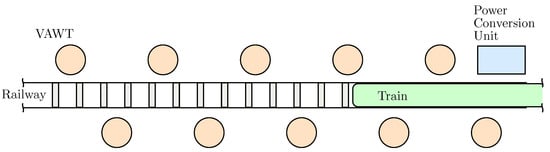
Figure 1.
Layout of the 10 VAWTs along the railway.
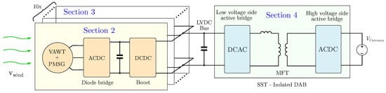
Figure 2.
Power conversion system.
To show this proposal, this paper is organized as follows: in Section 2, the wind energy conversion system is shown with the vertical axis wind turbine (VAWT), permanent magnet synchronous generator (PMSG), diode bridge and boost converter. Section 3 describes the parallelization of these converters. The Section 4 shows the delivery of generated power to catenary with the solid-state transformer (SST). In Section 5, some simulations and results are presented, ending with conclusions in Section 6.
2. Wind Energy Conversion
The target of the system is to inject power to the catenary of the railway. So the wind power conversion has several steps and issues to overcome, which is the technical goal of this paper, and the use of the local wind and air mass movement due to train quantization is the other object of this paper.
First of all, wind turbines are defined and located, which are mechanically connected to a PMSG. This PMSG generates three-phase AC currents so an ACDC converter has been connected and implemented a maximum power point algorithm in order to extract the most from the PMSG. This DC output simplifies the parallelization of the converters to add power to the system, which is discussed later.
2.1. Wind Turbine
The location of the wind turbines along the railway has been selected mainly according to be an open area of the railway, and a long enough track between stops. The open area helps to enhance the factor of utilization comparing to a tunnel placement, and the long track enables the high wind speed generated nearby the train (Figure 1). This location has an average wind speed of 5 m/s according to data and interpolations [14]. In order to estimate the wind energy nearby the train, some simulations have been carried out in [14], concluding in a generated wind speed of 7.7 m/s.
In these scenarios VAWTs give advantages over HAWTs mainly in two aspects [15,16]. VAWTs show a lower cut-in wind speed compared to HAWTs, and considering an average wind speed of 5 m/s and peak values over 7 m/s, VAWTs are more suitable in this context. On the other hand there is no need for wind direction control in VAWTs, so no matter the direction the train is moving, in contrast to the HAWTs.
2.2. PMSG Modelling
Using a direct drive-based permanent magnet synchronous generator (PMSG) significantly improves the reliability of the variable wind turbine, rather than using gear boxes [17,18,19]. The self-excitation capability of these generators due to permanent magnets, also improves efficiency. However, the variability in wind profiles leads fluctuations in torque of the wind turbine, affecting both in the output voltage and frequency. In order to show the dynamics involving in the generator, mechanical and electrical equations can be summarized as follows:
where J is the moment of inertia , is the angular speed of the rotor , D is the damping constant , and and are mechanical and electrical torques applied, respectively. Mechanical power applied to the generator by the VAWT () can be calculated by the equation defined in (2):
The electrical torque can be defined as shown in (3):
where p is the pole pairs of the generator, is the magnetic flux of the permanent magnets , and are equivalent inductance parameters in direct and quadrature axis, respectively; , and and are currents in direct and quadrature axis, respectively, of rotational frame of reference of the rotor .
The electrical frequency () and mechanical speed are related as follows in (4):
2.3. Diode Bridge and Boost Control: MPPT
As mentioned before, the three-phase voltage magnitude and frequency both depend on the rotational speed of the PMSG. In order to deliver electric power from the generator, it is desirable to generate the maximum power as possible, and there are several ways to do so. A common way to obtain maximum power point from the PMSG, is by using a fully controlled rectifier. However, in this paper, this has been done by using a diode bridge and a boost converter (Figure 2). Using the latter, the efficiency is lower and more harmonics are generated. Anyway, robustness and simplicity of control, which are essential features in small wind turbines, are substantially improved and the costs are lowered [20,21].
The three-phase diode bridge rectifies the alternating current to direct current. However, this voltage is not regulated and in order to get the maximum power, the algorithm has to deal with variables in control.
In order to deliver the maximum power of electric energy generation, maximum power point tracking (MPPT) techniques have been developed in the literature [22,23,24,25,26,27,28,29,30,31,32,33,34,35]. These techniques are broadly categorized into indirect power controller (IPC) and direct power controller (DPC). IPC techniques maximize the captured mechanical wind power, whereas DPC methods directly maximize the electrical power, indeed. Some of these MPPT techniques are listed and compared in Table 1.

Table 1.
Comparison of some MPPT techniques.
The method used to obtain the maximum power point in this system is the one so called Hill Climb Search (HCS). It is a DPC method, since it uses electrical parameters to obtain the maximum power point. Although the performance of this MPPT technique is moderate, it is very simple both from the point of view of the algorithm and the requirements needed. The amount of current delivered by each boost converter is calculated by measuring input current and voltage (Figure 3). This input current and voltage are multiplied in order to obtain the power. Perturbing the input current set point, the new power is calculated. Considering an increment/decrement in the set point and measuring the increment/decrement of the input power, the set point reaches the maximum power point by climbing the power hill.
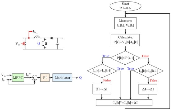
Figure 3.
Boost converter, control and Hill Climb Search MPPT algorithm.
3. Converter Parallelization
Considering two sources in parallel supplying a load, there is a need to avoid circulating current between both sources [36,37,38]. These currents generate undesired losses and fluctuations in the system, so to control the power delivery from paralleled converters there are several techniques [39,40,41,42,43,44]. Some of these techniques to control paralleled converters are classified in Figure 4.
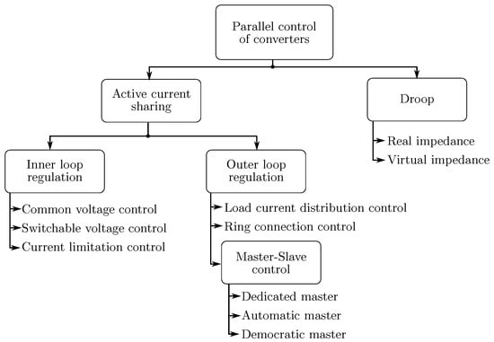
Figure 4.
Converter parallelization techniques.
It is important to point out that in DC the parallelization of converters is easier than in AC, due to the lack of wave synchronization both in phase and frequency [41,42].
According to the scenario of this proposal, the DAB is set to master the LVDC bus voltage, so that every wind generator and converter can inject power as a current source to the LVDC bus link. The DAB works as a dedicated voltage master, and the boost converters work as slave in current source mode. The small scale of the layout of the system allows the master-slave method, which simplifies the control of each converter. For a larger scale attempt, other techniques should be considered.
4. Power Delivery to Catenary: Isolated DAB
In SSTs an isolated dual active bridge (DAB) is a key topology [42,45]. This isolated DAB converter provides a high voltage ratio between low and high voltage sides, ensuring electrical isolation due to the Medium Frequency Transformer (MFT).
An active bridge is connected to the LVDC link, and by controlling the switching devices of the bridge, it is able to provide alternating voltage to the output. This alternating voltage is attached to the low-voltage side of the MFT. The other active bridge DC link is connected to the catenary, and the AC side of the bridge is connected to the high-voltage side of the MFT (Figure 5).
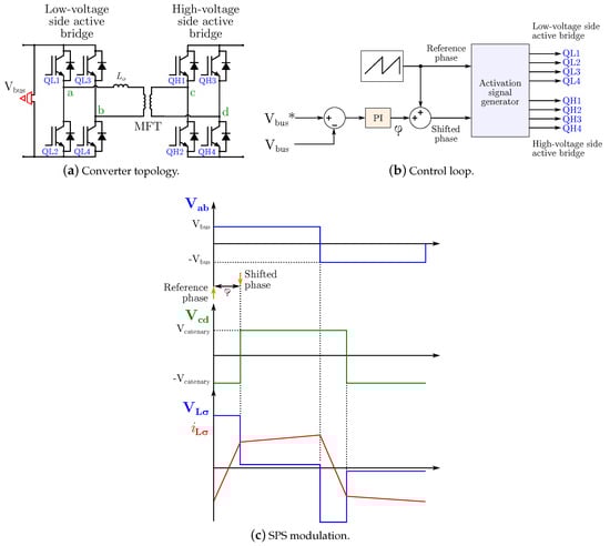
Figure 5.
Dual Active Bridge topology, control loop and SPS technique.
The MFTs are made of magnetically soft materials, such as nanocrystal or amorphous [45,46,47,48]. These materials show a narrow B-H curve, leading to the reduction in magnetic losses. Moreover, this loss reduction enables the use of a higher switching frequency for the same amount of power, which implies a size reduction as well.
According to modulation techniques, the first one proposed for this type of converters was the Single Phase Shift (SPS) [49]. Square wave signals are generated in both sides of the transformer controlling the switching devices of active bridges, with a phase shift between the two active bridges.
However, many improvements have been carried out adding PWM control to the phase shift control. Complexity has been added in mentioned techniques in order to reduce stress for the parasitic inductance, or to reduce switching losses of devices, among other improvements. In this context, some modulation techniques for the DAB are listed below:
- Single Phase Shift (SPS) [49,50,51];
- Extented Single Phase Shift (ESPS) [52];
- Dual Phase Shift (DPS) [53,54];
- Triple Phase Shift (TPS) [55,56];
- Hybrid Phase Shift (HPS) [57];
- Triangular Modulation (TRM) [58,59];
- Fundamental Component Analysis (FCA) [60,61];
- Fundamental Duty Modulation (FDM) [62].
In this paper, the SPS has been selected, since it is widely used and easy to implement [53,54,63]. The phase shift magnitude controls the active power flow between both sides of the DAB. In this work, the phase shift is controlled by setting the low side voltage to a DC value of 230 V (Figure 5b).
In the SPS technique, both active bridges work at of duty cycle, generating square waves in the AC side of each bridge. The activation signal generator of the Figure 5b, generates the activation signals for each IGBT in the DAB. The reference phase sets the starting point of one of the square waves, and the other square wave starting point starts phase shifted according to the output of the control. The Medium Frequency Transformer converts voltage ratios, and the inductor is the device which defines the power flow direction. In Figure 5c, the SPS technique is shown according to the phase shift control variable . In this context, the controlled loop is the low voltage side bus (LVDC). Setting the LVDC of the DAB, fixes the output voltage of every boost converter, which are connected in parallel. So the DAB works as a master controller for parallel connected slave boost converters, as mentioned earlier. The power flow of the DAB can be calculated as shown in (5).
where n is the transformation ratio, is the LVDC bus voltage, is the MVDC voltage, is the switching frequency of the DAB switching devices, is the DAB inductance and is the phase shift variable control in the SPS technique.
5. Model and Simulation Results
5.1. Simulation Model
The wind energy harnessing system has been modeled in Matlab®/Simulink®. The VAWT, PMSG and the boost converter are shown in Figure 6a, and the SST model is shown in Figure 6b, listing the parameter values in Table 2.
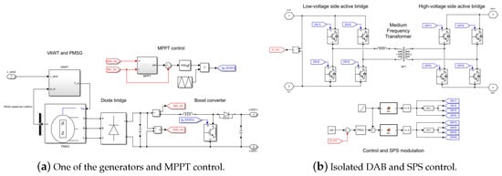
Figure 6.
System models.
Table 2.
Parameters of the model.
In Figure 6a, the generator and the wind turbine are modeled. The wind turbine parameters behavior has been approximated as the parameters shown by the manufacturer. The control of the boost converter has been as a current source, in order to simplify the parallelization of other boost converters.
In Figure 6b the DAB model and the SPS control are shown. The DAB model reads the and compares with the set point value. Controlling this parameter, the controller outputs a phase shift, which is added to the reference phase for square waves. In this context, the power delivered depends on the generated power by all the generators.
5.2. Simulation Results
The average wind speed in the location is about 5 m/s without the train going by. Moreover, the wind speed while the train goes by has been simulated in order to estimate it, concluding a maximum wind speed of 7.7 m/s nearby the wind turbine [14]. In Figure 7, the torque and rotational speed of the PMSG during the train displacement are plotted.
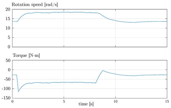
Figure 7.
Torque and rotational speed of the PMSG.
The rotational speed of the generator increases as expected. Being rotating before the train goes by, gives an advantage compared to a stopped turbine, since the generator is already delivering power.
The plotted voltage, current and power in Figure 8, tries to show the changes in their value according to the scenario of the train going by. Both the voltage and current change due to the MPPT technique, to extract the maximum power in every instant.
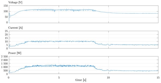
Figure 8.
Voltage, current and power at the input of the boost converter.
In Figure 9, the electric power generated by two of the sources are compared due to time delay between both of them. In a constant wind speed of 5 m/s, each generator can achieve almost 400 W of power, and while the train goes by, each source is able to generate about 1200 W.
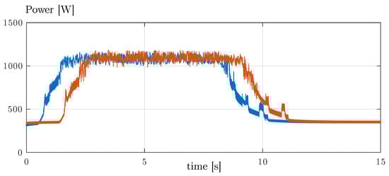
Figure 9.
Power generated by two generators along the railway.
The Figure 10 shows the constant bus voltage controlled by the DAB, ensuring the constant value of the LVDC bus voltage even with current injection to it.
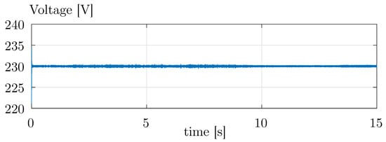
Figure 10.
LVDC bus voltage.
Finishing with simulation results, the total power delivered to the catenary is plotted in blue in Figure 11, generating up to 11 kW of peak power, and almost 3.5 kW with a constant wind speed of 5 m/s.
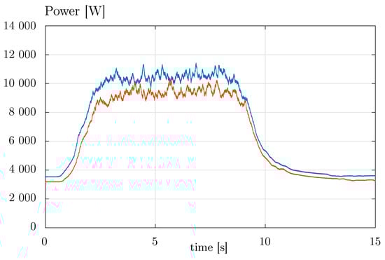
Figure 11.
Whole system output power (blue) and with one faulty boost converter (red).
In order to show the generated energy data, the wind energy in the location without the wind generated by the train would be about 31 MWh. Taking into account the influence of the train, which can be estimated about 1.33 MWh, the total energy generated could be around 32.3 MWh. This energy is estimated by the simulation results with 10 VAWTs, and as mentioned before, this can be scalable.
5.3. Faulty Scenario
Considering one faulty boost converter, the Figure 11 plots the power delivered of the whole system to the catenary in this conditions.
In this faulty condition the energy generated in a whole year would be about 27.9 MWh, and adding up the influence of the train, the total amount of energy would be about 29 MWh. This result shows that the impact of a faulty boost converter is not negligible. However, the system do not present instability in this conditions.
6. Conclusions
This paper proposes a power electronics approach with the aim of empowering the railway infrastructure by connecting several VAWTs nearby the railway to take advantage of both wind and the air mass displacement due to trains. This topology of power conversion is a proof of concept, in which it has been proven that it is feasible and simulations show good results. Research have been done in order to get MPPT from a wind powered PMSG, also to parallelize DC converters, and the power flow control in a DAB.
As mentioned earlier, this proposal shows an easily scalable control for each generator. Even if one of the MPPT control of a boost converter shows an inadequate behavior, this paper shows that it only affects in the amount of generated power, not in the stability of the whole system.
This proposal also shows the scalability of the whole system with simple boost control, taking advantage of both local wind and the wind generated by the train displacement.
The simulations with 10 VAWTs conclude that this proposal is able to generate about 3.5 kW with the average wind speed, reaching a peak power of 11 kW when the train goes by. In this situation, the system is able to generate 32.3 MWh in a year. The train movement generates almost the 10% of the annual energy. Having a faulty generator, this proposal show that does not affect to the stability of the system, just in delivering lower power to the catenary.
Author Contributions
All authors contributed to the design and implementation of the research, providing critical feedback and helping shape the research, analysis and manuscript. All authors have read and agreed to the published version of the manuscript.
Funding
The authors thank the support from the Basque Government (project ELKARTEK Twin KK-2020/00050, GISEL Research Group IT1191-19 and PIBA_2019_1_0098), as well as from the University of the Basque Country UPV/EHU (COLAB19/02, under Grant PES16/31).
Conflicts of Interest
The authors declare no conflict of interest.
References
- IEA. World Energy Balances 2018; IEA: Paris, France, 2018. [Google Scholar]
- IEA. Tracking Transport 2020; IEA: Paris, France, 2020. [Google Scholar]
- Falcone, P.M.; Lopolito, A.; Sica, E. The networking dynamics of the Italian biofuel industry in time of crisis: Finding an effective instrument mix for fostering a sustainable energy transition. Energy Policy 2018, 112, 334–348. [Google Scholar] [CrossRef]
- Helliwell, R.; Tomei, J. Practicing stewardship: EU biofuels policy and certification in the UK and Guatemala. Agric. Hum. Values 2016, 34, 473–484. [Google Scholar] [CrossRef]
- Bae, C.; Jang, D.; Kim, Y.; Chang, S.; Mok, J. Calculation of regenerative energy in DC 1500V electric railway substations. In Proceedings of the Internatonal Conference on Power Electronics, Daegu, Korea, 22–26 October 2007; pp. 801–805. [Google Scholar] [CrossRef]
- Abril, M.; Barber, F.; Ingolotti, L.; Salido, M.A.; Tormos, P.; Lova, A. An assessment of railway capacity. Transp. Res. Part E Logist. Transp. Rev. 2008, 44, 774–806. [Google Scholar] [CrossRef]
- Falcone, P.M. Analysing stakeholders’ perspectives towards a socio-technical change: The energy transition journey in Gela Municipality. AIMS Energy 2018, 6, 645. [Google Scholar] [CrossRef]
- Laskar, M.A.R. Piezoelectricity: An Energy Source for Future Railway Stations. SEU J. Sci. Eng. 2017, 11. [Google Scholar] [CrossRef]
- Baker, C. The flow around high speed trains. J. Wind Eng. Ind. Aerodyn. 2010, 98, 277–298. [Google Scholar] [CrossRef]
- Kwon, H.B.; Park, C.S. An experimental study on the relationship between ballast flying phenomenon and strong wind under high speed train. In Proceedings of the World Congress on Rail Research, Montreal, QC, Canada, 3–6 June 2006. [Google Scholar]
- Joshi, S.; Mathur, A.; Jain, A.; Gupta, S.; Jani, N.; Chhabra, B. Generation of electricity using wind energy produced due to the motion of trains. J. Energy Technol. Policy 2012, 2, 19–23. [Google Scholar]
- Kumar, A.; Karandikar, P.; Chavan, D.S. Generating and saving energy by installing wind turbines along the railway tracks. In Proceedings of the 2015 International Conference on Energy Systems and Applications, Pune, India, 30 October–1 November 2015. [Google Scholar] [CrossRef]
- Pan, H.; Li, H.; Zhang, T.; Laghari, A.A.; Zhang, Z.; Yuan, Y.; Qian, B. A portable renewable wind energy harvesting system integrated S-rotor and H-rotor for self-powered applications in high-speed railway tunnels. Energy Convers. Manag. 2019, 196, 56–68. [Google Scholar] [CrossRef]
- Asensio, F.J.; San Martín, J.I.; Zamora, I.; Oñederra, O.; Saldaña, G.; Eguia, P. A system approach to harnessing wind energy in a railway infrastructure. In Proceedings of the Annual Conference of the IEEE Industrial Electronics Society (IECON), Washington, DC, USA, 21–23 October 2018; pp. 1646–1651. [Google Scholar] [CrossRef]
- Vivek, C.M.; Gopikrishnan, P.; Murugesh, R.; Mohamed, R.R. A review on vertical and horizontal axis wind turbine. Int. Res. J. Eng. Technol. 2017, 4, 240–250. [Google Scholar]
- Battisti, L.; Benini, E.; Brighenti, A.; Dell’Anna, S.; Castelli, M.R. Small wind turbine effectiveness in the urban environment. Renew. Energy 2018, 129, 102–113. [Google Scholar] [CrossRef]
- Li, S.; Haskew, T.A.; Xu, L. Conventional and novel control designs for direct driven PMSG wind turbines. Electr. Power Syst. Res. 2010, 80, 328–338. [Google Scholar] [CrossRef]
- Shehata, E.G. A comparative study of current control schemes for a direct-driven PMSG wind energy generation system. Electr. Power Syst. Res. 2017, 143, 197–205. [Google Scholar] [CrossRef]
- Devashish, T.A. A comprehensive review on wind energy system for electric power generation: Current situation and improved technologies to realize future development. Int. J. Renew. Energy Res. 2017, 7, 1786–1805. [Google Scholar]
- Urtasun, A.; Sanchis, P.; Martín, I.S.; López, J.; Marroyo, L. Modeling of small wind turbines based on PMSG with diode bridge for sensorless maximum power tracking. Renew. Energy 2013, 55, 138–149. [Google Scholar] [CrossRef]
- Baroudi, J.A.; Dinavahi, V.; Knight, A.M. A review of power converter topologies for wind generators. Renew. Energy 2007, 32, 2369–2385. [Google Scholar] [CrossRef]
- Kumar, D.; Chatterjee, K. A review of conventional and advanced MPPT algorithms for wind energy systems. Renew. Sustain. Energy Rev. 2016, 55, 957–970. [Google Scholar] [CrossRef]
- Kumar, M.B.H.; Saravanan, B.; Sanjeevikumar, P.; Blaabjerg, F. Review on control techniques and methodologies for maximum power extraction from wind energy systems. IET Renew. Power Gener. 2018, 12, 1609–1622. [Google Scholar] [CrossRef]
- Abdullah, M.; Yatim, A.; Tan, C.; Saidur, R. A review of maximum power point tracking algorithms for wind energy systems. Renew. Sustain. Energy Rev. 2012, 16, 3220–3227. [Google Scholar] [CrossRef]
- Kot, R.; Rolak, M.; Malinowski, M. Comparison of maximum peak power tracking algorithms for a small wind turbine. Math. Comput. Simul. 2013, 91, 29–40. [Google Scholar] [CrossRef]
- Cheng, M.; Zhu, Y. The state of the art of wind energy conversion systems and technologies: A review. Energy Convers. Manag. 2014, 88, 332–347. [Google Scholar] [CrossRef]
- Menezes, E.J.N.; Araújo, A.M.; da Silva, N.S.B. A review on wind turbine control and its associated methods. J. Clean. Prod. 2018, 174, 945–953. [Google Scholar] [CrossRef]
- Sarkar, J.; Khule, S.S. A study of MPPT schemes in PMSG based wind turbine system. In Proceedings of the International Conference on Electrical, Electronics, and Optimization Techniques (ICEEOT), Chennai, India, 3–5 March 2016; pp. 100–105. [Google Scholar] [CrossRef]
- Nasiri, M.; Milimonfared, J.; Fathi, S.H. Modeling, analysis and comparison of TSR and OTC methods for MPPT and power smoothing in permanent magnet synchronous generator-based wind turbines. Energy Convers. Manag. 2014, 86, 892–900. [Google Scholar] [CrossRef]
- Wei, C.; Zhang, Z.; Qiao, W.; Qu, L. An adaptive network-based reinforcement learning method for MPPT control of PMSG wind energy conversion systems. IEEE Trans. Power Electron. 2016, 31, 7837–7848. [Google Scholar] [CrossRef]
- Dalala, Z.M.; Zahid, Z.U.; Yu, W.; Cho, Y.; Lai, J. Design and analysis of an MPPT technique for small-scale wind energy conversion systems. IEEE Trans. Energy Convers. 2013, 28, 756–767. [Google Scholar] [CrossRef]
- Llano, D.X.; McMahon, R.A. Control techniques with system efficiency comparison for microwind turbines. IEEE Trans. Sustain. Energy 2017, 8, 1609–1617. [Google Scholar] [CrossRef]
- Jeong, H.G.; Seung, R.H.; Lee, K.B. An Improved Maximum Power Point Tracking Method for Wind Power Systems. Energies 2012, 5, 1339–1354. [Google Scholar] [CrossRef]
- Kolesnik, S.; Kuperman, A. Analytical Derivation of Electrical-Side Maximum Power Line for Wind Generators. Energies 2017, 10, 1498. [Google Scholar] [CrossRef]
- Syahputra, R.; Soesanti, I. Performance Improvement for Small-Scale Wind Turbine System Based on Maximum Power Point Tracking Control. Energies 2019, 12, 3938. [Google Scholar] [CrossRef]
- Augustine, S.; Mishra, M.K.; Lakshminarasamma, N. Circulating current minimization and current sharing control of parallel boost converters based on droop index. In Proceedings of the IEEE International Symposium on Diagnostics for Electric Machines, Power Electronics and Drives (SDEMPED), Valencia, Spain, 27–30 August 2013; pp. 454–460. [Google Scholar] [CrossRef]
- Dragičević, T.; Lu, X.; Vasquez, J.C.; Guerrero, J.M. DC Microgrids—Part I: A Review of Control Strategies and Stabilization Techniques. IEEE Trans. Power Electron. 2016, 31, 4876–4891. [Google Scholar]
- Zheng, X.; Ali, H.; Wu, X.; Zaman, H.; Khan, S. Non-Linear Behavioral Modeling for DC-DC Converters and Dynamic Analysis of Distributed Energy Systems. Energies 2017, 10, 63. [Google Scholar] [CrossRef]
- Gao, F.; Bozhko, S.; Costabeber, A.; Patel, C.; Wheeler, P.; Hill, C.I.; Asher, G. Comparative stability analysis of droop control approaches in voltage-source-converter-based DC microgrids. IEEE Trans. Power Electron. 2016, 32, 2395–2415. [Google Scholar] [CrossRef]
- Chiang, H.; Jen, K.; You, G. Improved droop control method with precise current sharing and voltage regulation. IET Power Electron. 2016, 9, 789–800. [Google Scholar] [CrossRef]
- Huang, Y.; Tse, C.K. Circuit theoretic classification of parallel connected DC-DC converters. IEEE Trans. Circuits Syst. I Regul. Pap. 2007, 54, 1099–1108. [Google Scholar] [CrossRef]
- Freijedo, F.D.; Rodriguez-Diaz, E.; Dujic, D. Stable and passive high-power dual active bridge converters interfacing MVDC grids. IEEE Trans. Ind. Electron. 2018, 65, 9561–9570. [Google Scholar] [CrossRef]
- Xiong, F.; Wu, J.; Hao, L.; Liu, Z. Backflow Power Optimization Control for Dual Active Bridge DC-DC Converters. Energies 2017, 10, 1403. [Google Scholar] [CrossRef]
- Vazquez, A.; Martin, K.; Arias, M.; Sebastian, J. On Bidirectional DC Nano-Grids: Design Considerations and an Architecture Proposal. Energies 2019, 12, 3715. [Google Scholar] [CrossRef]
- Yuan, L.; Lu, Z.; Sun, J.; Duan, R.; Zhao, Z. Comparative evaluation of isolated bidirectional DC/DC converter in high-power high-frequency occasions. In Proceedings of the International Conference on Electrical Machines and Systems (ICEMS), Jeju, Korea, 7–10 October 2018. [Google Scholar] [CrossRef]
- Samejima, T.; Kintsu, K.; Morizane, T.; Kimura, N. Comparison of core material of high frequency transformer for offshore wind generation. In Proceedings of the International Symposium on Power Electronics, Electrical Drives, Automation and Motion (SPEEDAM), Amalfi, Italy, 20–22 June 2018. [Google Scholar] [CrossRef]
- Yeh, C.S.; Lai, J.S. A study on high frequency transformer design in medium-voltage solid-state transformers. In Proceedings of the Asian Conference on Energy, Power and Transportation Electrification (ACEPT), Singapore, 30 October–2 November 2018. [Google Scholar] [CrossRef]
- Sarker, P.C.; Islam, M.R.; Guo, Y.; Zhu, J.; Lu, H.Y. State-of-the-art technologies for development of high frequency transformers with advanced magnetic materials. IEEE Trans. Appl. Supercond. 2019, 29, 1–11. [Google Scholar] [CrossRef]
- Doncker, R.W.A.A.D.; Divan, D.M.; Kheraluwala, M.H. A three-phase soft-switched high-power-density DC/DC converter for high-power applications. IEEE Trans. Ind. Appl. 1991, 27, 63–73. [Google Scholar] [CrossRef]
- Qin, H.; Kimball, J.W. Closed-loop control of DC–DC dual-active-bridge converters driving single-phase inverters. IEEE Trans. Power Electron. 2014, 29, 1006–1017. [Google Scholar] [CrossRef]
- Song, W.; Hou, N.; Wu, M. Virtual direct power control scheme of dual active bridge DC–DC converters for fast dynamic response. IEEE Trans. Power Electron. 2018, 33, 1750–1759. [Google Scholar] [CrossRef]
- Zhao, B.; Yu, Q.; Sun, W. Extended-phase-shift control of isolated bidirectional DC–DC converter for power distribution in microgrid. IEEE Trans. Power Electron. 2012, 27, 4667–4680. [Google Scholar] [CrossRef]
- Karthikeyan, V.; Gupta, R. Closed-loop control of isolated dual active bridge converter using dual phase shift modulation. In Proceedings of the Annual Conference of the IEEE Industrial Electronics Society (IECON), Yokohama, Japan, 9–12 November 2015. [Google Scholar] [CrossRef]
- Bai, H.; Mi, C. Eliminate reactive power and increase system efficiency of isolated bidirectional dual-active-bridge DC–DC converters using novel dual-phase-shift control. IEEE Trans. Power Electron. 2008, 23, 2905–2914. [Google Scholar] [CrossRef]
- Wu, K.; de Silva, C.W.; Dunford, W.G. Stability analysis of isolated bidirectional dual active full-bridge DC–DC converter with triple phase-shift control. IEEE Trans. Power Electron. 2012, 27, 2007–2017. [Google Scholar] [CrossRef]
- Calderon, C.; Barrado, A.; Rodriguez, A.; Alou, P.; Lazaro, A.; Fernandez, C.; Zumel, P. General Analysis of Switching Modes in a Dual Active Bridge with Triple Phase Shift Modulation. Energies 2018, 11, 2419. [Google Scholar] [CrossRef]
- Zhou, H.; Khambadkone, A.M. Hybrid modulation for dual-active-bridge bidirectional converter with extended power range for ultracapacitor application. IEEE Trans. Ind. Appl. 2009, 45, 1434–1442. [Google Scholar] [CrossRef]
- Jauch, F.; Biela, J. Generalized modeling and optimization of a bidirectional dual active bridge DC-DC converter including frequency variation. In Proceedings of the International Power Electronics Conference (IPEC), Hiroshima, Japan, 18–21 May 2014. [Google Scholar] [CrossRef]
- Krismer, F.; Round, S.; Kolar, J.W. Performance optimization of a high current dual active bridge with a wide operating voltage range. In Proceedings of the IEEE Power Electronics Specialists Conference, Jeju, Korea, 18–22 June 2006. [Google Scholar] [CrossRef]
- Itoh, J.-i.; Higa, H.; Nagano, T. A novel control method focusing on reactive power for a dual active bridge converter. In Proceedings of the International Power Electronics and Application Conference and Exposition, Shanghai, China, 5–8 November 2014. [Google Scholar] [CrossRef]
- Zhao, B.; Song, Q.; Liu, W.; Liu, G.; Zhao, Y. Universal high-frequency-link characterization and practical fundamental-optimal strategy for dual-active-bridge DC-DC converter under PWM plus phase-shift control. IEEE Trans. Power Electron. 2015, 30, 6488–6494. [Google Scholar] [CrossRef]
- Choi, W.; Rho, K.M.; Cho, B.H. Fundamental duty modulation of dual-active-bridge converter for wide-range operation. IEEE Trans. Power Electron. 2016, 31, 4048–4064. [Google Scholar] [CrossRef]
- Shi, L.; Lei, W.; Li, Z.; Cui, Y.; Huang, J.; Wang, Y. Stability analysis of digitally controlled dual active bridge converters. J. Mod. Power Syst. Clean Energy 2017, 6, 375–383. [Google Scholar] [CrossRef]
Publisher’s Note: MDPI stays neutral with regard to jurisdictional claims in published maps and institutional affiliations. |
© 2020 by the authors. Licensee MDPI, Basel, Switzerland. This article is an open access article distributed under the terms and conditions of the Creative Commons Attribution (CC BY) license (http://creativecommons.org/licenses/by/4.0/).