A State of the Art of the Multilevel Inverters with Reduced Count Components


Abstract
1. Introduction
2. Conventional Multilevel Inverters
2.1. Diode Clamped Multilevel Inverter Topology (DCMLI)
2.2. Flying Capacitor Multilevel Inverter (FCMLIs)
2.3. Cascaded H-Bridge Multilevel Inverter (CHBMLIs)
3. Reduced Components Multilevel Inverter
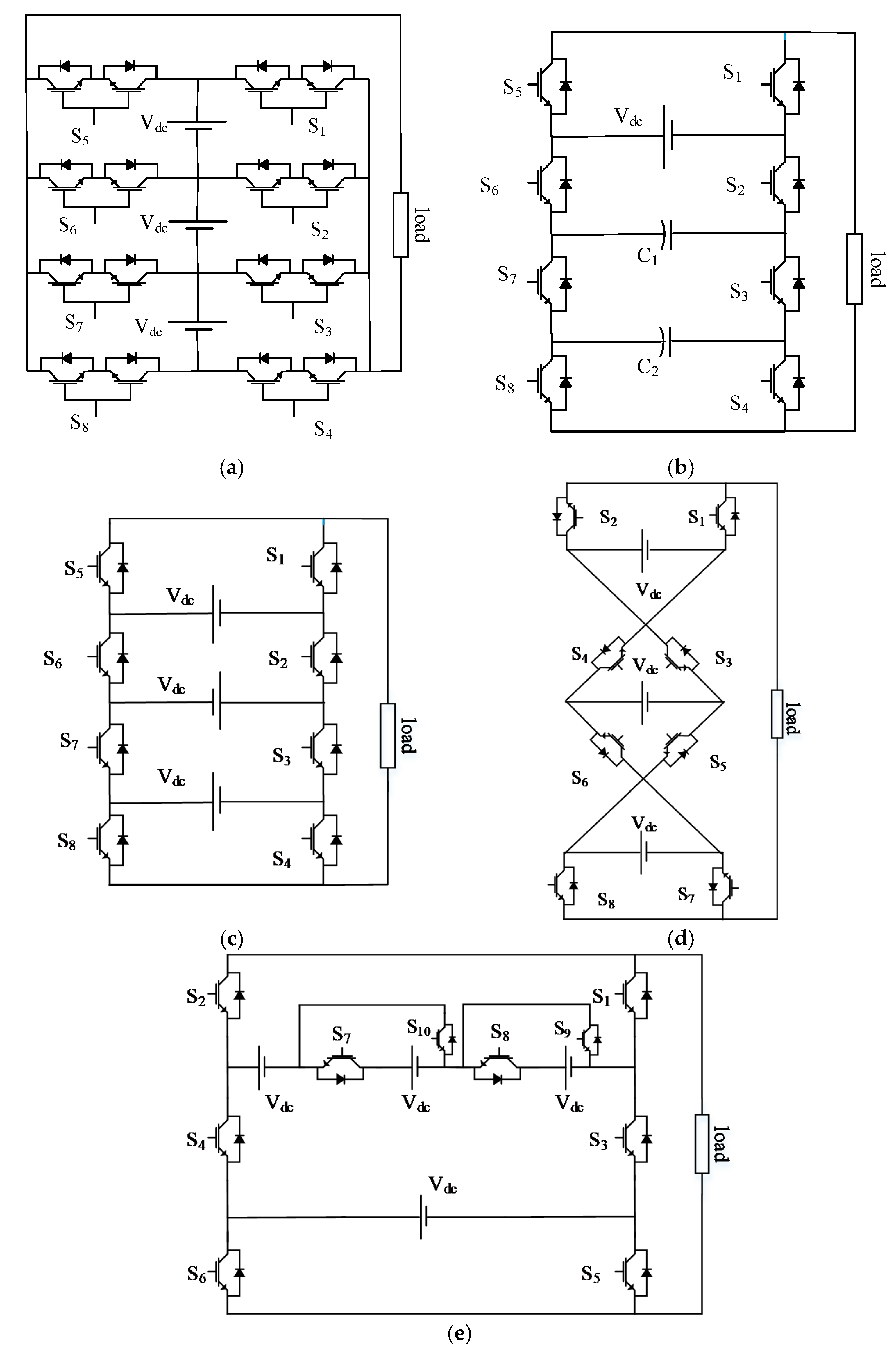
3.1. Symmetrical Multilevel Inverter Topologies
3.1.1. Symmetrical MLI with H-Bridge
3.1.2. Symmetrical MLI without H-Bridge
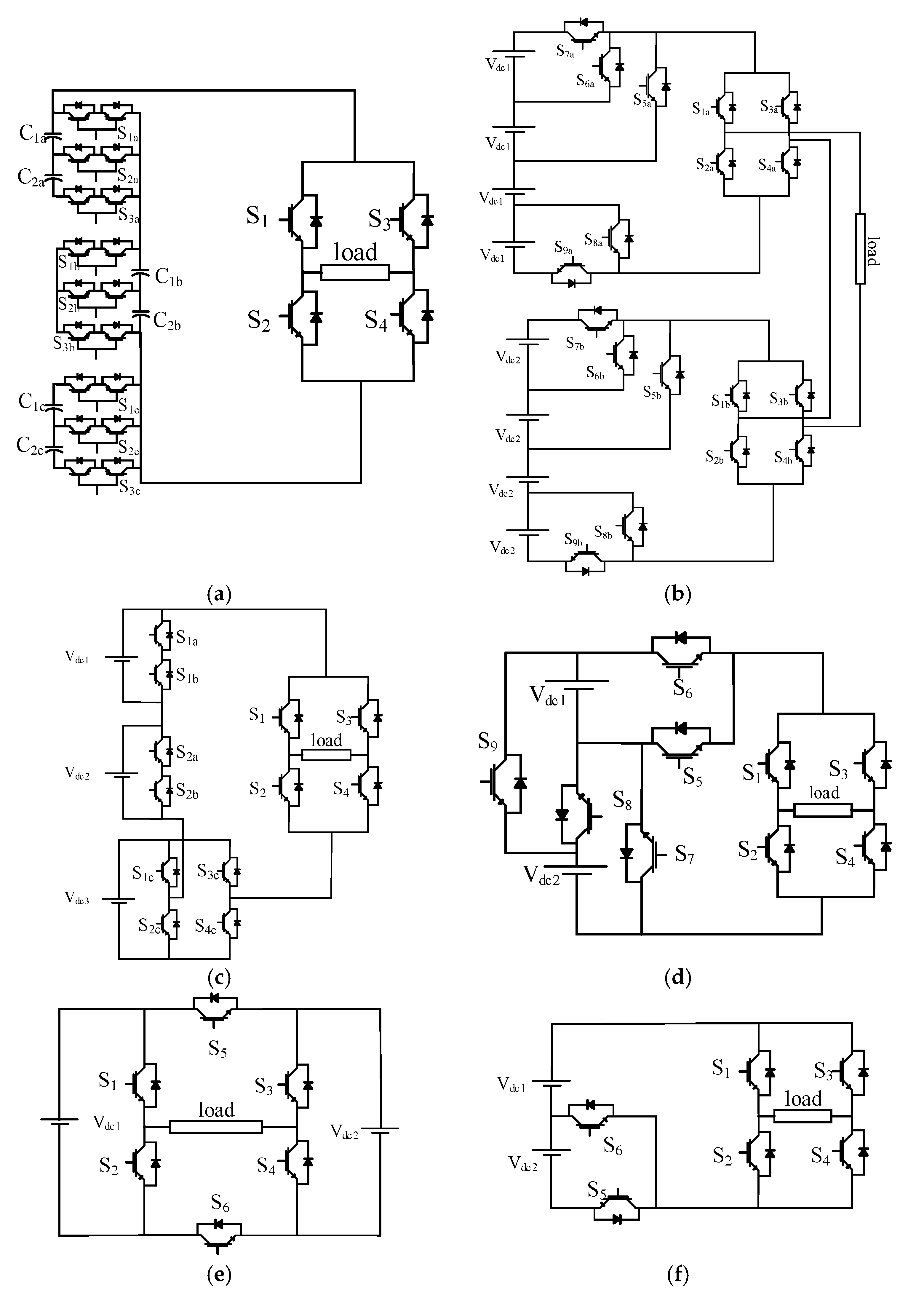
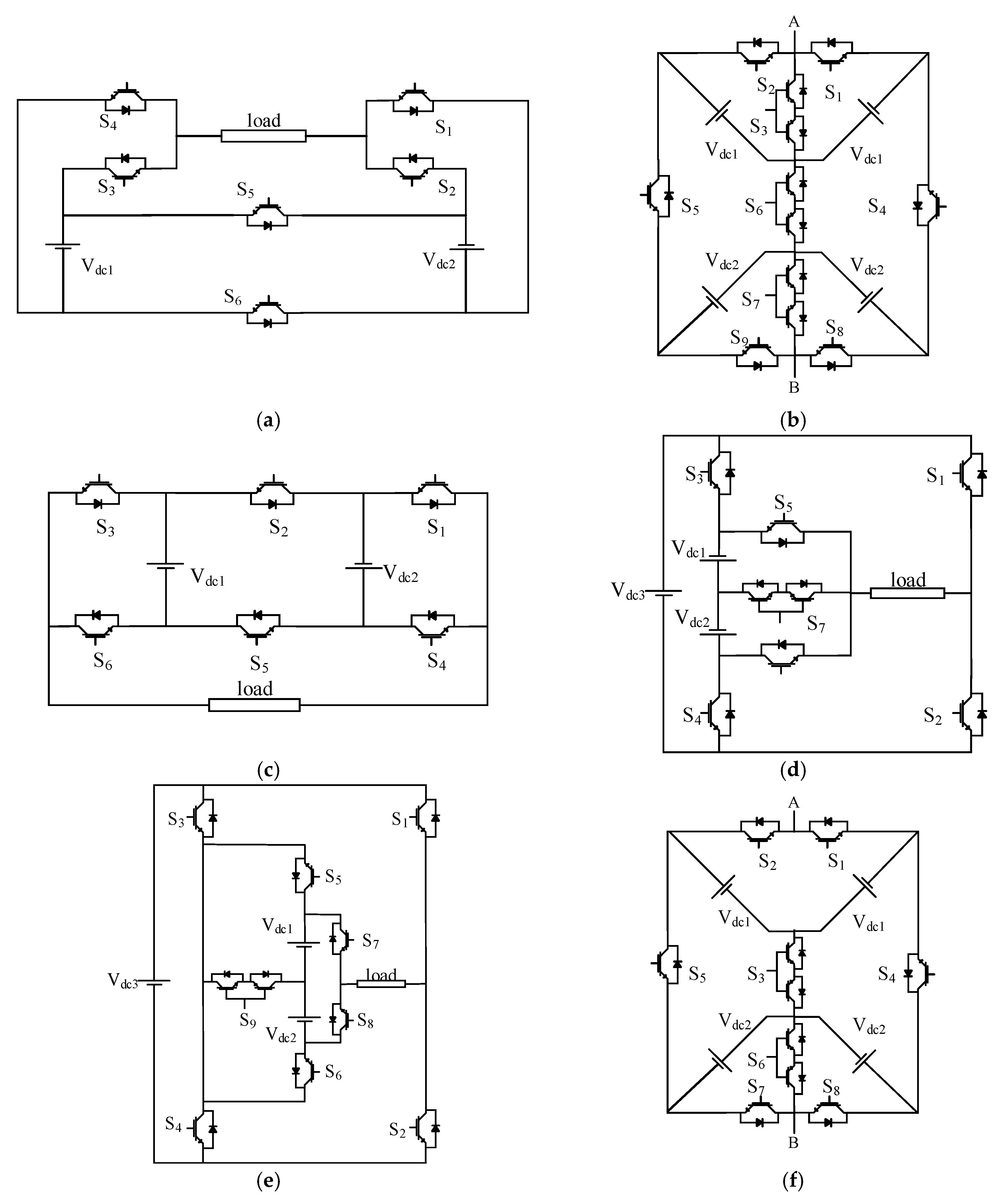
3.2. Asymmetrical Multilevel Inverter Topologies
- Change topologies from symmetrical into asymmetrical by replacing the symmetrical DC suppliers with asymmetrical suppliers while keeping the structure of the topology unchanged.
- In other cases, the asymmetrical topologies were implemented by repeating the basic cell with different values of the input DC suppliers based on binary or trinary sequence.
- Change the structure of the symmetrical topology to be compatible with the asymmetrical feeding suppliers.
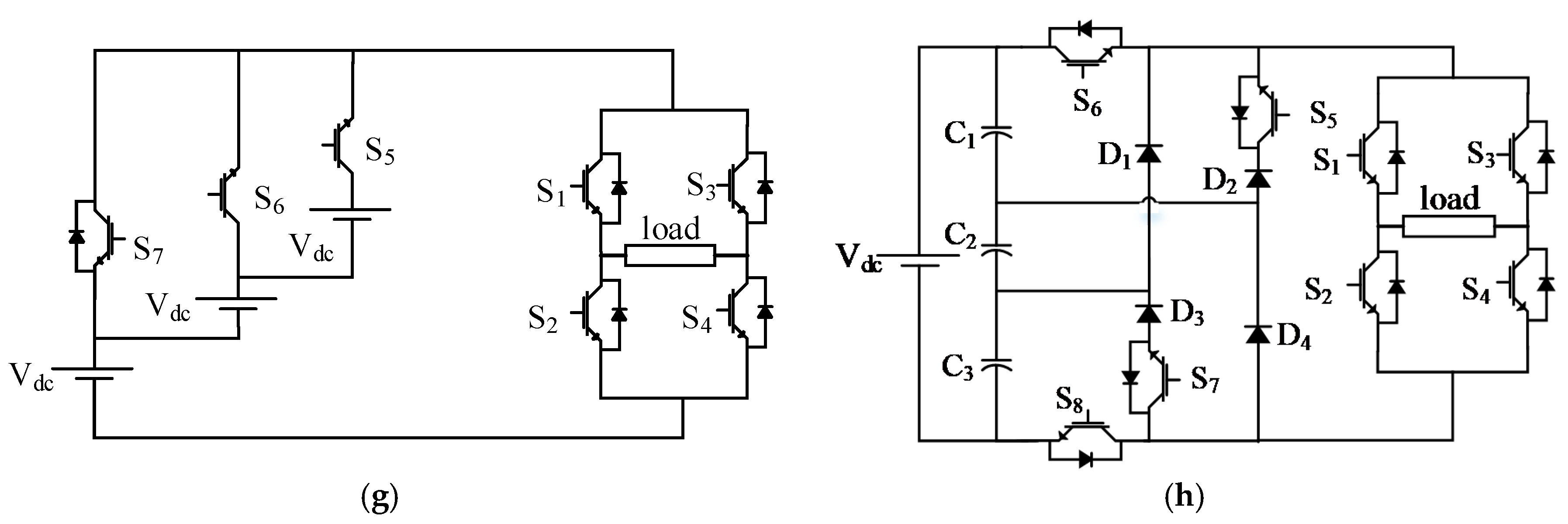
3.2.1. Asymmetrical MLI Topologies with H-Bridge
3.2.2. Asymmetrical MLI without H-Bridge
3.3. Hybrid Multilevel Inverter Topologies
4. Modular Multilevel Converters (MMC)
- (1)
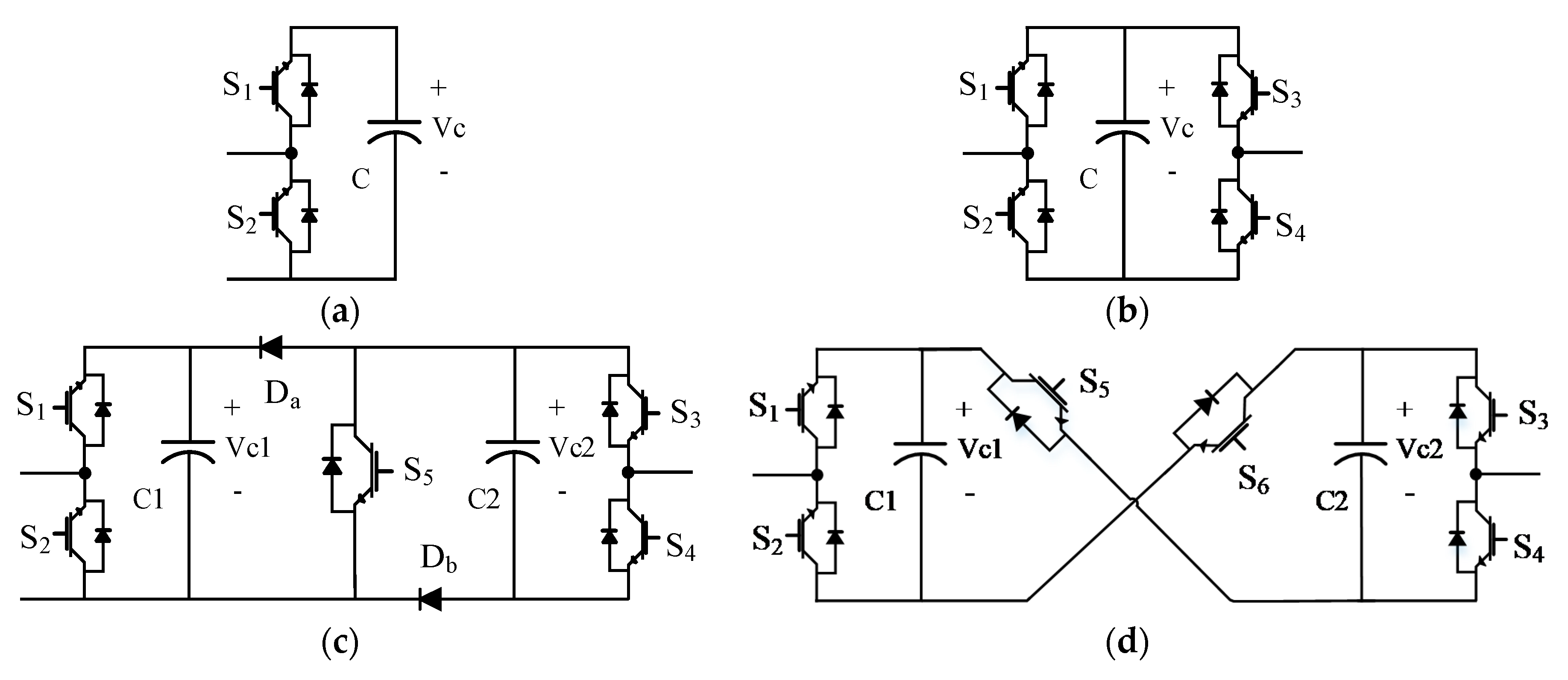
- The half-bridge submodule circuit [75]: the SM unit configuration circuit has been illustrated in Figure 12a. It basically consisted of two power switches and a capacitor acted as a power source in parallel with the switches. The output voltage of this basic cell could be equal to the capacitor voltage in the case of firing the switch S1 ON, or zero if S2 is in the ON state. So, the switches S1and S2 operate complimentarily.
- (2)
- The full-bridge submodule circuit [76]: another configuration for the SM in the MMCs is the full bridge. The basic cell of the full-bridge SM consisted of four switching devices and capacitors arranged in the form of a bridge, this arrangement is presented in Figure 12b. Every two switches in the same arm of the basic cell operate complimentarily.
- (3)
- (4)
- The three-level converter submodule circuit [78]: the configuration for this SM is the same as the configuration of the three-level NPC circuit and the three-level FC circuit, which is presented in Figure 5a,b, respectively. The output voltage waveform from this unit is a three-level output voltage (0, Vc1, Vc1 + Vc2).
- (5)
- The five-level cross-connected submodule circuit [79]: the configuration of this SM consists of two half-bridge cells back to back and in between, there are two power switches in the cross direction. The structure of this SM is presented in Figure 12d. Based on the title of this SM the output voltage contains five levels (0, Vc1, Vc2, Vc1 + Vc2).
- (6)
- A comparison has been held between the different SMs to differentiate between them. This comparison takes into account the number of components for each SM unit, the number of levels in the output voltage waveform each cell, and the size of the output losses in the SM unit. The comparison between the different structures for the SMs is presented in Table 3.
5. Performance Parameters of the Compared MLI Topologies
5.1. Total Number of Components per Pole
- NCom/Lev: Number of components per pole for each level in the output voltage waveform.
- NSup: Number of DC power suppliers that were used to feed the topologies.
- NCap: Number of capacitors in the proposed topology.
- NTran: Number of transformers.
- NSw: Number of switching devices.
- ND: Number of diodes in the converter circuit.
- NPoles: Number of levels in the voltage waveform per pole.
- NAux: Any auxiliary components in the converter circuit.
5.2. Average Active Switches per Pole
5.3. Total Standing Voltage
5.4. Total Harmonic Distortion (THD)
5.5. Overall Efficiency
5.6. Circulating Current
6. Conclusions
Author Contributions
Funding
Conflicts of Interest
References
- Prabaharan, N.; Palanisamy, K. A comprehensive review on reduced switch multilevel inverter topologies, modulation techniques and applications. Renew. Sustain. Energy Rev. 2017, 76, 1248–1282. [Google Scholar] [CrossRef]
- Kala, P.; Arora, S. A comprehensive study of classical and hybrid multilevel inverter topologies for renewable energy applications. Renew. Sustain. Energy Rev. 2017, 76, 905–931. [Google Scholar] [CrossRef]
- Jahns, T.M.; Blasko, V. Recent advances in power electronics technology for industrial and traction machine drives. Proc. IEEE 2001, 89, 963–975. [Google Scholar] [CrossRef]
- Kaboli, S. Reliability in Power Electronics and Electrical Machines: Industrial Applications and Performance Models; IGI Global: Hershey, PA, USA, 2016. [Google Scholar]
- Zhang, G.; Li, Z.; Zhang, B.; Halang, W.A. Power electronics converters: Past, present and future. Renew. Sustain. Energy Rev. 2018, 81, 2028–2044. [Google Scholar] [CrossRef]
- Wu, B.; Narimani, M. High-Power Converters and AC Drives; John Wiley & Sons: Hoboken, NJ, USA, 2017. [Google Scholar]
- Yuan, X.; Barbi, I. Fundamentals of a new diode clamping multilevel inverter. IEEE Trans. Power Electron. 2000, 15, 711–718. [Google Scholar] [CrossRef]
- Newton, C.; Sumner, M. Novel technique for maintaining balanced internal DC link voltages in diode clamped five-level inverters. IEE Proc.-Electr. Power Appl. 1999, 146, 341–349. [Google Scholar] [CrossRef]
- Pan, Z.; Peng, F.Z.; Corzine, K.A.; Stefanovic, V.R.; Leuthen, J.M.; Gataric, S. Voltage balancing control of diode-clamped multilevel rectifier/inverter systems. IEEE Trans. Ind. Appl. 2005, 41, 1698–1706. [Google Scholar] [CrossRef]
- Shukla, A.; Ghosh, A.; Joshi, A. Control schemes for DC capacitor voltages equalization in diode-clamped multilevel inverter-based DSTATCOM. IEEE Trans. Power Deliv. 2008, 23, 1139–1149. [Google Scholar] [CrossRef]
- Marchesoni, M.; Tenca, P. Diode-clamped multilevel converters: A practicable way to balance DC-link voltages. IEEE Trans. Ind. Electron. 2002, 49, 752–765. [Google Scholar] [CrossRef]
- Peng, F.Z.; Lai, J.-S.; McKeever, J.W.; Van Coevering, J. A multilevel voltage-source inverter with separate DC sources for static var generation. IEEE Trans. Ind. Appl. 1996, 32, 1130–1138. [Google Scholar] [CrossRef]
- Escalante, M.F.; Vannier, J.-C.; Arzandé, A. Flying capacitor multilevel inverters and DTC motor drive applications. IEEE Trans. Ind. Electron. 2002, 49, 809–815. [Google Scholar] [CrossRef]
- Lin, B.; Huang, C. Analysis and implementation of a single-phase capacitor-clamped inverter with simple structure. IEE Proc.-Electr. Power Appl. 2004, 151, 555–562. [Google Scholar] [CrossRef]
- Rodriguez, J.; Lai, J.-S.; Peng, F.Z. Multilevel inverters: A survey of topologies, controls, and applications. IEEE Trans. Ind. Electron. 2002, 49, 724–738. [Google Scholar] [CrossRef]
- Peng, F.; McKeever, J.; Adams, D. Cascade multilevel inverters for utility applications. In Proceedings of the IECON’97 23rd International Conference on Industrial Electronics, Control, and Instrumentation (Cat. No. 97CH36066), New Orleans, LA, USA, 14 November 1997; pp. 437–442. [Google Scholar]
- Corzine, K.; Familiant, Y. A new cascaded multilevel H-bridge drive. IEEE Trans. Power Electron. 2002, 17, 125–131. [Google Scholar] [CrossRef]
- Rodríguez, J.; Bernet, S.; Wu, B.; Pontt, J.O.; Kouro, S. Multilevel voltage-source-converter topologies for industrial medium-voltage drives. IEEE Trans. Ind. Electron. 2007, 54, 2930–2945. [Google Scholar] [CrossRef]
- Tolbert, L.; Peng, F.Z.; Cunnyngham, T.; Chiasson, J.N. Charge balance control schemes for cascade multilevel converter in hybrid electric vehicles. IEEE Trans. Ind. Electron. 2002, 49, 1058–1064. [Google Scholar] [CrossRef]
- Tolbert, L.M.; Peng, F.Z.; Habetler, T.G. Multilevel inverters for electric vehicle applications. In Proceedings of the Power Electronics in Transportation (Cat. No. 98TH8349), Dearborn, MI, USA, 22–23 October 1998; pp. 79–84. [Google Scholar]
- Colak, I.; Kabalci, E.; Bayindir, R. Review of multilevel voltage source inverter topologies and control schemes. Energy Convers. Manag. 2011, 52, 1114–1128. [Google Scholar] [CrossRef]
- Chen, A.; He, X. Research on hybrid-clamped multilevel-inverter topologies. IEEE Trans. Ind. Electron. 2006, 53, 1898–1907. [Google Scholar] [CrossRef]
- Suresh, Y.; Panda, A.K. Investigation on hybrid cascaded multilevel inverter with reduced dc sources. Renew. Sustain. Energy Rev. 2013, 26, 49–59. [Google Scholar] [CrossRef]
- Panda, A.K.; Suresh, Y. Research on cascade multilevel inverter with single DC source by using three-phase transformers. Int. J. Electr. Power Energy Syst. 2012, 40, 9–20. [Google Scholar] [CrossRef]
- Ali, A.I.; Sayed, M.A.; Mohamed, E.E.; Azmy, A.M. Advanced Single-Phase Nine-Level Converter for the Integration of Multiterminal DC Supplies. IEEE J. Emerg. Sel. Top. Power Electron. 2018, 7, 1949–1958. [Google Scholar] [CrossRef]
- Hassan, A.M.; Yang, X.; Ali, A.I.; Ahmed, T.A.; Azmy, A.M. A Study of Level-Shifted PWM Single-phase 11-Level Multilevel Inverter. In Proceedings of the 2019 21st International Middle East Power Systems Conference (MEPCON), Cairo, Egypt, 31 October–7 November 2019; pp. 170–176. [Google Scholar]
- Su, G.-J. Multilevel DC-link inverter. IEEE Trans. Ind. Appl. 2005, 41, 848–854. [Google Scholar] [CrossRef]
- Babaei, E.; Hosseini, S.H. New cascaded multilevel inverter topology with minimum number of switches. Energy Convers. Manag. 2009, 50, 2761–2767. [Google Scholar] [CrossRef]
- Babaei, E.; Laali, S.; Bayat, Z. A single-phase cascaded multilevel inverter based on a new basic unit with reduced number of power switches. IEEE Trans. Ind. Electron. 2014, 62, 922–929. [Google Scholar] [CrossRef]
- Alishah, R.S.; Nazarpour, D.; Hosseini, S.H.; Sabahi, M. Novel multilevel inverter topologies for medium and high-voltage applications with lower values of blocked voltage by switches. IET Power Electron. 2014, 7, 3062–3071. [Google Scholar] [CrossRef]
- Hinago, Y.; Koizumi, H. A single-phase multilevel inverter using switched series/parallel dc voltage sources. IEEE Trans. Ind. Electron. 2009, 57, 2643–2650. [Google Scholar] [CrossRef]
- Babaei, E.; Gowgani, S.S.; Sabahi, M. Modified multilevel inverters using series and parallel connection of dc voltage sources. Arab. J. Sci. Eng. 2014, 39, 3077–3094. [Google Scholar] [CrossRef]
- Tsunoda, A.; Hinago, Y.; Koizumi, H. Level-and phase-shifted PWM for seven-level switched-capacitor inverter using series/parallel conversion. IEEE Trans. Ind. Electron. 2013, 61, 4011–4021. [Google Scholar] [CrossRef]
- Feloups, C.E.S.; Mohamed, E.E.M. A Novel Reduced Components Model Predictive Controlled Multilevel Inverter for Grid-Tied Applications. Adv. Electr. Electron. Eng. 2019, 17, 251–261. [Google Scholar] [CrossRef]
- Hsieh, C.-H.; Liang, T.-J.; Chen, S.-M.; Tsai, S.-W. Design and implementation of a novel multilevel DC–AC inverter. IEEE Trans. Ind. Appl. 2016, 52, 2436–2443. [Google Scholar] [CrossRef]
- Babaei, E. Optimal topologies for cascaded sub-multilevel converters. J. Power Electron. 2010, 10, 251–261. [Google Scholar] [CrossRef]
- Babaei, E.; Hosseini, S.; Gharehpetian, G.; Haque, M.T.; Sabahi, M. Reduction of dc voltage sources and switches in asymmetrical multilevel converters using a novel topology. Electr. Power Syst. Res. 2007, 77, 1073–1085. [Google Scholar] [CrossRef]
- Ounejjar, Y.; Al-Haddad, K.; Gregoire, L.-A. Packed U cells multilevel converter topology: Theoretical study and experimental validation. IEEE Trans. Ind. Electron. 2010, 58, 1294–1306. [Google Scholar] [CrossRef]
- Gupta, K.K.; Jain, S. Multilevel inverter topology based on series connected switched sources. IET Power Electron. 2013, 6, 164–174. [Google Scholar] [CrossRef]
- Gupta, K.K.; Jain, S. A novel multilevel inverter based on switched DC sources. IEEE Trans. Ind. Electron. 2013, 61, 3269–3278. [Google Scholar] [CrossRef]
- Liao, Y.-H.; Lai, C.-M. Newly-constructed simplified single-phase multistring multilevel inverter topology for distributed energy resources. IEEE Trans. Power Electron. 2011, 26, 2386–2392. [Google Scholar] [CrossRef]
- Kangarlu, M.F.; Babaei, E. Cross-switched multilevel inverter: An innovative topology. IET Power Electron. 2013, 6, 642–651. [Google Scholar] [CrossRef]
- Banaei, M.R.; Oskuee, M.R.J.; Khounjahan, H. Reconfiguration of semi-cascaded multilevel inverter to improve systems performance parameters. IET Power Electron. 2014, 7, 1106–1112. [Google Scholar] [CrossRef]
- Gurpinar, E.; Castellazzi, A. Single-phase T-type inverter performance benchmark using Si IGBTs, SiC MOSFETs, and GaN HEMTs. IEEE Trans. Power Electron. 2015, 31, 7148–7160. [Google Scholar] [CrossRef]
- Ebrahimi, J.; Babaei, E.; Gharehpetian, G.B. A new topology of cascaded multilevel converters with reduced number of components for high-voltage applications. IEEE Trans. Power Electron. 2011, 26, 3109–3118. [Google Scholar] [CrossRef]
- Ebrahimi, J.; Babaei, E.; Gharehpetian, G.B. A new multilevel converter topology with reduced number of power electronic components. IEEE Trans. Ind. Electron. 2011, 59, 655–667. [Google Scholar] [CrossRef]
- Babaei, E.; Kangarlu, M.F.; Sabahi, M.; Pahlavani, M.R.A. Cascaded multilevel inverter using sub-multilevel cells. Electr. Power Syst. Res. 2013, 96, 101–110. [Google Scholar] [CrossRef]
- Beser, E.; Camur, S.; Arifoglu, B.; Beser, E.K. Design and application of a novel structure and topology for multilevel inverter. In Proceedings of the 2008 International Symposium On Power Electronics, Electrical Drives, Automation and Motion, Ischia, Italy, 11–13 June 2008; pp. 969–974. [Google Scholar]
- Waltrich, G.; Barbi, I. Three-phase cascaded multilevel inverter using power cells with two inverter legs in series. In Proceedings of the 2009 IEEE Energy Conversion Congress and Exposition, San Jose, CA, USA, 20–24 September 2009; pp. 3085–3092. [Google Scholar]
- Babaei, E.; Dehqan, A.; Sabahi, M. Improvement of the performance of the cascaded multilevel inverters using power cells with two series legs. J. Power Electron. 2013, 13, 223–231. [Google Scholar] [CrossRef]
- Arif, M.; Ayob, S.; Salam, Z. Asymmetrical Nine-level inverter topology with reduce power semicondutor devices. Telkomnika 2018, 16, 38–45. [Google Scholar] [CrossRef]
- bin Arif, M.S.; Ayob, S.M.; Salam, Z. Asymmetrical multilevel inverter topology with reduced power semiconductor devices. In Proceedings of the 2016 IEEE Industrial Electronics and Applications Conference (IEACon), Kota Kinabalu, Malaysia, 20–22 November 2016; pp. 20–25. [Google Scholar]
- Babaei, E.; Laali, S. Optimum structures of proposed new cascaded multilevel inverter with reduced number of components. IEEE Trans. Ind. Electron. 2015, 62, 6887–6895. [Google Scholar] [CrossRef]
- Babaei, E.; Alilu, S.; Laali, S. A new general topology for cascaded multilevel inverters with reduced number of components based on developed H-bridge. IEEE Trans. Ind. Electron. 2013, 61, 3932–3939. [Google Scholar] [CrossRef]
- Babaei, E.; Laali, S.; Bahravar, S. A new cascaded multi-level inverter topology with reduced number of components and charge balance control methods capabilities. Electr. Power Compon. Syst. 2015, 43, 2116–2130. [Google Scholar] [CrossRef]
- Mesquita, S.; Antunes, F.; Daher, S. A new bidirectional hybrid multilevel inverter with 49-level output voltage using a single dc voltage source and reduced number of on components. Electr. Power Syst. Res. 2017, 143, 703–714. [Google Scholar] [CrossRef]
- Boora, K.; Kumar, J. General topology for asymmetrical multilevel inverter with reduced number of switches. IET Power Electron. 2017, 10, 2034–2041. [Google Scholar] [CrossRef]
- Samadaei, E.; Sheikholeslami, A.; Gholamian, S.A.; Adabi, J. A square T-type (ST-Type) module for asymmetrical multilevel inverters. IEEE Trans. Power Electron. 2017, 33, 987–996. [Google Scholar] [CrossRef]
- Babadi, A.N.; Salari, O.; Mojibian, M.J.; Bina, M.T. Modified multilevel inverters with reduced structures based on PackedU-Cell. IEEE J. Emerg. Sel. Top. Power Electron. 2017, 6, 874–887. [Google Scholar] [CrossRef]
- Salari, E.; Falehi, A.D. A novel 49-level asymmetrical modular multilevel inverter: Analysis, comparison and validation. Analog Integr. Circuits Signal Process. 2019, 101, 611–622. [Google Scholar] [CrossRef]
- Siddique, M.D.; Mekhilef, S.; Shah, N.M.; Memon, M.A. Optimal design of a new cascaded multilevel inverter topology with reduced switch count. IEEE Access 2019, 7, 24498–24510. [Google Scholar] [CrossRef]
- Siddique, M.D.; Mekhilef, S.; Shah, N.M.; Sarwar, A.; Iqbal, A.; Memon, M.A. A new multilevel inverter topology with reduce switch count. IEEE Access 2019, 7, 58584–58594. [Google Scholar] [CrossRef]
- Samadaei, E.; Gholamian, S.A.; Sheikholeslami, A.; Adabi, J. An envelope type (E-Type) module: Asymmetric multilevel inverters with reduced components. IEEE Trans. Ind. Electron. 2016, 63, 7148–7156. [Google Scholar] [CrossRef]
- Samadaei, E.; Kaviani, M.; Bertilsson, K. A 13-levels module (K-type) with two DC sources for multilevel inverters. IEEE Trans. Ind. Electron. 2018, 66, 5186–5196. [Google Scholar] [CrossRef]
- Zeng, J.; Lin, W.; Cen, D.; Junfeng, L. Novel K-Type Multilevel Inverter with Reduced Components and Self-Balance. IEEE J. Emerg. Sel. Top. Power Electron. 2019, 8, 4343–4354. [Google Scholar] [CrossRef]
- Barzegarkhoo, R.; Zamiri, E.; Moradzadeh, M.; Shadabi, H. Symmetric hybridised design for a novel step-up 19-level inverter. IET Power Electron. 2017, 10, 1377–1391. [Google Scholar] [CrossRef]
- Abarzadeh, M.; Al-Haddad, K. Generalized circuit topology of Qn-hybrid-NPC multilevel converter with novel decomposed sensor-less modulation method. IEEE Access 2019, 7, 59813–59824. [Google Scholar] [CrossRef]
- Abarzadeh, M.; Al-Haddad, K. An improved active-neutral-point-clamped converter with new modulation method for ground power unit application. IEEE Trans. Ind. Electron. 2018, 66, 203–214. [Google Scholar] [CrossRef]
- Abarzadeh, M.; Kojabadi, H.M. A static ground power unit based on the improved hybrid active neutral-point-clamped converter. IEEE Trans. Ind. Electron. 2016, 63, 7792–7803. [Google Scholar] [CrossRef]
- Lee, S.S.; Sidorov, M.; Lim, C.S.; Idris, N.R.N.; Heng, Y.E. Hybrid cascaded multilevel inverter (HCMLI) with improved symmetrical 4-level submodule. IEEE Trans. Power Electron. 2017, 33, 932–935. [Google Scholar] [CrossRef]
- Lezana, P.; Aceitón, R. Hybrid multicell converter: Topology and modulation. IEEE Trans. Ind. Electron. 2010, 58, 3938–3945. [Google Scholar] [CrossRef]
- Kaliamoorthy, M.; Rajasekaran, V.; Raj, I.G.C.; Raj, L.H.T. Generalised hybrid switching topology for a single-phase modular multilevel inverter. IET Power Electron. 2014, 7, 2472–2485. [Google Scholar] [CrossRef]
- Gautam, S.P.; Kumar, L.; Gupta, S. Hybrid topology of symmetrical multilevel inverter using less number of devices. IET Power Electron. 2015, 8, 2125–2135. [Google Scholar] [CrossRef]
- Meraj, S.T.; Yahaya, N.Z.; Hasan, K.; Masaoud, A. Single phase 21 level hybrid multilevel inverter with reduced power components employing low frequency modulation technique. Int. J. Power Electron. Drive Syst. 2020, 11, 810. [Google Scholar]
- Thitichaiworakorn, N.; Hagiwara, M.; Akagi, H. Experimental verification of a modular multilevel cascade inverter based on double-star bridge cells. IEEE Trans. Ind. Appl. 2013, 50, 509–519. [Google Scholar] [CrossRef]
- Akagi, H. New trends in medium-voltage power converters and motor drives. In Proceedings of the 2011 IEEE International Symposium on Industrial Electronics, Gdansk, Poland, 27–30 June 2011; pp. 5–14. [Google Scholar]
- Ilves, K.; Taffner, F.; Norrga, S.; Antonopoulos, A.; Harnefors, L.; Nee, H.-P. A submodule implementation for parallel connection of capacitors in modular multilevel converters. IEEE Trans. Power Electron. 2014, 30, 3518–3527. [Google Scholar] [CrossRef]
- Solas, E.; Abad, G.; Barrena, J.A.; Aurtenetxea, S.; Carcar, A.; Zając, L. Modular multilevel converter with different submodule concepts—Part I: Capacitor voltage balancing method. IEEE Trans. Ind. Electron. 2012, 60, 4525–4535. [Google Scholar] [CrossRef]
- Nami, A.; Wang, L.; Dijkhuizen, F.; Shukla, A. Five level cross connected cell for cascaded converters. In Proceedings of the 2013 15th European Conference on Power Electronics and Applications (EPE), Lille, France, 3–5 September 2013; pp. 1–9. [Google Scholar]
- Salem, A.; Ahmed, E.M.; Orabi, M.; Ahmed, M. New three-phase symmetrical multilevel voltage source inverter. IEEE J. Emerg. Sel. Top. Circuits Syst. 2015, 5, 430–442. [Google Scholar] [CrossRef]
- Khamooshi, R.; Namadmalan, A. Converter utilisation ratio assessment for total harmonic distortion optimisation in cascaded H-bridge multi-level inverters. IET Power Electron. 2016, 9, 2103–2110. [Google Scholar] [CrossRef]
- Bharatiraja, C.; Sanjeevikumar, P.; Munda, J.; Norum, L.; Raghu, S. Mitigation of circulating current in diode clamped MLI fed induction motor drive using carrier shifting PWM techniques. In Advances in Systems, Control and Automation; Springer: Berlin/Heidelberg, Germany, 2018; pp. 71–83. [Google Scholar]
- Bharatiraja, C.; Jeevananthan, S.; Munda, J.; Latha, R. Improved SVPWM vector selection approaches in OVM region to reduce common-mode voltage for three-level neutral point clamped inverter. Int. J. Electr. Power Energy Syst. 2016, 79, 285–297. [Google Scholar] [CrossRef]
- Deng, F.; Yu, Q.; Wang, Q.; Zhu, R.; Cai, X.; Chen, Z. Suppression of DC-link current ripple for modular multilevel converters under phase-disposition PWM. IEEE Trans. Power Electron. 2019, 35, 3310–3324. [Google Scholar] [CrossRef]
- Santhakumar, C.; Shivakumar, R.; Bharatiraja, C.; Sanjeevikumar, P. Carrier shifting algorithms for the mitigation of circulating current in diode clamped MLI fed induction motor drive. Int. J. Power Electron. Drive Syst. 2017, 8, 844. [Google Scholar] [CrossRef]
- Madichetty, S.; Dasgupta, A.; Mishra, S.; Panigrahi, C.K.; Basha, G. Application of an advanced repetitive controller to mitigate harmonics in MMC with APOD scheme. IEEE Trans. Power Electron. 2015, 31, 6112–6121. [Google Scholar] [CrossRef]
- Lee, I.-O.; Moon, G.-W. Phase-shifted PWM converter with a wide ZVS range and reduced circulating current. IEEE Trans. Power Electron. 2012, 28, 908–919. [Google Scholar] [CrossRef]


| Topology | Advantages | Disadvantages |
|---|---|---|
| (DCMLIs) [7,8,9,10,11] | 1—Depend on only single DC supply. 2—Simple structure and easy to be implemented. 3—Reduce number of components compared to the conventional inverters for the same number of steps. 4—System expansion is allowable. 5—For fundamental frequency switching operation the efficiency is high. | 1—Diodes with different voltage ratings for clamping diodes are required. 2—Real power flow is difficult because of the capacitors imbalance and it tends to overcharge or discharge. 3—Need high voltage rating diodes to block the reverse voltages. 4—Extra switches, capacitors, and diodes are required for increasing the output voltage levels. |
| (FCMLIs) [12,13,14] | 1—Simple structure. 2—Reduced number of components compared to the conventional inverters for the same number of components. 3—Has a wide range of industrial applications especially in the medium and high power applications. 4—Single power supply is needed. 5—System supports modularity. 6—Deep voltage sags and short duration outages problems can be overcome through the large number of capacitors in the inverter. | 1—Large numbers of capacitors are bulky and more expensive than the clamping diodes. 2—Complex control is required to maintain the capacitor’s voltage balance. 3—Switching utilization and Efficiency are poor for real power transmission. |
| (CHBMLIs) [15,16,17,18,19,20] | 1—Compared to the DCMLIs and FCMLIs it synthesizes a reduced number of switching devices. 2—It is applicable for symmetrical and asymmetrical operation. 3—No need for the power diodes or the bulky capacitors. 4—System can be extended to a high level of output power by connecting multiple units of the basic unit in series connection. 5—Has a wide range of renewable energy generation applications especially in the PV power applications. | 1—Large numbers of DC suppliers in the case of system extending. 2—Extra switches and DC suppliers are required for increasing the output voltage levels. |
| Category | Ref. | Advantages | Disadvantages |
|---|---|---|---|
| Symmetrical MLI topologies | [25,26,30] | - Highly modular and simple - Applicable for renewable energy applications - It requires non-isolated input DC sources | - Requires high number of DC suppliers - Uses unidirectional and bidirectional switches - Asymmetrical sources cannot be used |
| [27,28,29,31] | - Only unidirectional switches required - Simple structure and easy to be extended | -Many components are required for system extending - In [29] the symmetrical sources are mandatory | |
| [36] | - Simple structure and easy to be implemented - Modularity is available | -It uses bidirectional switches, which increase the size and the cost of the system | |
| [38,39,40,42] | - It replaces the bidirectional switches in [36] into a unidirectional set of switches | - Switches with different rates are required - Complex control | |
| [43] | - Easy and simple structure - System support modularity - Uses only bidirectional switches. | - Asymmetry is not possible - Switches with different ratings are required. | |
| Asymmetrical MLI topologies | [46] | - Simple structure and easy implementation - Non-isolated DC sources are required - Operates at high and fundamental switching frequencies | - Load sharing is not equal - Uses unidirectional as well as bidirectional switches, which increases the losses and size. |
| [47,49,50] | - Available for symmetrical and asymmetrical applications - Supports modularity process | - The basic cell in [47] cannot be operated in the symmetrical configuration so it can be cascaded | |
| [51,52] | - Reduced number of components - Use in the hybrid renewable energy sources applications | - Symmetric source configuration is not possible. | |
| [53,54,55] | - Simple and symmetric structure - Reduced number of components are required - Supports the symmetrical and asymmetrical configuration - All the switches are unidirectional switches | - Modularity is not available in these configurations, so it can be extended through the cascaded connection process | |
| [56] | - Single DC source is required with the aid of a multi-terminal high switching frequency transformer - System expansion process is available | - Complex to control - High level of leakages in case of the high switching frequency operation - High current spikes. | |
| [58,63] | - Simple structure - Reduced number of switches for high number of steps | - Uses mix of unidirectional and bidirectional power switches | |
| [64,65] | - Reduced the number of DC suppliers and compensated with the chargeable DC capacitors - Self-balancing process | - Uses both the unidirectional and bidirectional during the system implementation - The system expansion process is not easy and needs more additional components | |
| Hybrid MLI topologies | [66] | - High number of steps in the output waveform - Reduced number of components. | - It uses a mix of unidirectional and bidirectional power switches - Diodes with a different rating are required |
| [67,68,69] | - Reduces the losses and costs - Control strategy ensures a self-balancing for the capacitor - The system implementation based only on the unidirectional power switches | - Complex control - In case of system expansion the complexity of the system increases | |
| [72,73] | - Simple structure - Reduced number of DC suppliers and substituted with the virtual DC sources - No need for the isolated DC power sources | - The charging and balancing process of the capacitors is complex - Uses unidirectional as well as bidirectional power switches - High circulating current. - Asymmetric source configuration is not possible |
| SM Configuration | Number of Components | Number of Output Levels | Size of Losses |
|---|---|---|---|
| half-bridge | 2switches+ capacitor | 2 | It handles low power losses because it uses less switches compared to the other SM configurations. |
| full bridge | 4switches+ capacitor | 2 | Due to the relatively large number of switches compared to MMC based half bridge, the power losses, as well as the cost, increased. |
| The clamp-double | 5switches+ 2capacitors + 2diodes | 5 | This configuration records a higher percentage of power losses compared to the MMC based half-bridge and a lower percentage compared to the MMC based full bridge. |
| The three-level converter: NPC | 4switches+ 2capacitors + 2diodes | 3 | The MMC based FCSM has the same power losses compared to MMC based half bridge SM; however, the MMC based NPCSM has high power losses compared to the MMC based half bridge SM. However, the complexity of the circuit, as well as the capacitor voltage balancing difficulties, limit the use of this configuration. |
| The three-level converter: FC | 4switches+ 2capacitors | 3 | |
| The five-level cross-connected | 6switches+ 2capacitors | 5 | This configuration has the same amount of power losses compared to the MMC based clamped-double SM. |
| Ref. | Lev | References Specifications | Performance Parameters | |||||||||
|---|---|---|---|---|---|---|---|---|---|---|---|---|
| NSup | NCap | NTran | NSw | ND | NPoles | NAux | NCom/Lev | Navg/pole | TSV p.u | THD | ||
| DCMLI | 3 | 1 | 2 | 0 | 4 | 2 | 2 | 0 | 4.5 | 2.5 | 2 | 69.8% |
| FCMLI | 3 | 1 | 3 | 0 | 4 | 0 | 2 | 0 | 4 | 2 | 2 | 63.75% |
| CHBMLI | 3 | 1 | 0 | 0 | 4 | 0 | 2 | 0 | 2.5 | 2 | 2 | 48% |
| [25] | 9 | 4 | 0 | 0 | 10 | 3 | 5 | 0 | 3.4 | 2.8 | 16 | 17.9% |
| [26] | 11 | 5 | 0 | 0 | 12 | 4 | 6 | 0 | 3.5 | 2.83 | 23 | 11.4% |
| [27,28] | 7 | 3 | 0 | 0 | 10 | 0 | 4 | 0 | 3.25 | 4.25 | 16 | 22.6% |
| [29] | 9 | 4 | 0 | 0 | 11 | 0 | 5 | 0 | 2.8 | 5.2 | 20 | - |
| [30] | 7 | 3 | 0 | 0 | 8 | 0 | 4 | 0 | 2.75 | 2.5 | 10 | 9.27% |
| [31] | 11 | 3 | 0 | 0 | 10 | 0 | 6 | 0 | 2.16 | 2.33 | 17 | 9.07% |
| [34] | 7 | 3 | 0 | 0 | 7 | 2 | 4 | 0 | 3 | 3.25 | 12 | - |
| [35] | 7 | 1 | 3 | 0 | 8 | 4 | 4 | 0 | 4 | 3 | 21 | - |
| [36,37] | 13 | 3 | 0 | 0 | 16 | 0 | 7 | 0 | 2.75 | 2.29 | 24 | 6.33% |
| [38] | 7 | 1 | 1 | 0 | 6 | 0 | 4 | 0 | 2 | 3 | 12 | 22.45% |
| [39,40] | 5 | 3 | 0 | 0 | 8 | 0 | 3 | 0 | 3.66 | 5.33 | 18 | 31.5% |
| [42] | 7 | 3 | 0 | 0 | 8 | 0 | 4 | 0 | 2.75 | 4 | 12 | - |
| [43] | 9 | 4 | 0 | 0 | 10 | 0 | 5 | 0 | 2.8 | 4.2 | 18 | 12.66% |
| [47,48] | 13 | 4 | 0 | 0 | 16 | 0 | 7 | 0 | 2.86 | 4 | 24 | - |
| [49,50] | 15 | 3 | 0 | 0 | 12 | 0 | 8 | 0 | 1.875 | 6.25 | 22 | - |
| [51,52] | 9 | 2 | 0 | 0 | 9 | 0 | 5 | 0 | 2.2 | 3.6 | 18 | 9.19% |
| [55] | 5 | 2 | 0 | 0 | 6 | 0 | 3 | 0 | 2.67 | 3 | 8 | 17.56% |
| [56] | 49 | 1 | 0 | 4 | 28 | 0 | 25 | 0 | 1.32 | 4 | 128 | 8.77% |
| [57] | 7 | 2 | 0 | 0 | 6 | 0 | 4 | 0 | 2 | 3 | 12 | 16.4% |
| [58] | 17 | 4 | 0 | 0 | 12 | 0 | 9 | 0 | 1.78 | 4.11 | 40 | 2.77% |
| [61] | 11 | 3 | 0 | 0 | 8 | 0 | 6 | 0 | 1.83 | 3.33 | 21 | - |
| [62] | 15 | 3 | 0 | 0 | 10 | 0 | 8 | 0 | 1.625 | 4.375 | 34 | - |
| [64] | 13 | 2 | 2 | 0 | 14 | 0 | 7 | 0 | 2.57 | 5.14 | 32 | 3.87% |
| [65] | 13 | 2 | 4 | 0 | 12 | 2 | 7 | 0 | 2.86 | 5.57 | 6 | 5.31% |
| [66] | 19 | 2 | 4 | 0 | 12 | 6 | 10 | 0 | 2.4 | 6.2 | 38 | - |
| [67] | 21 | 2 | 3 | 0 | 14 | 4 | 11 | 0 | 2.1 | 4.54 | 60 | 6.25% |
| [70] | 9 | 4 | 0 | 0 | 10 | 0 | 5 | 0 | 2.8 | 3.2 | 26 | - |
| [73] | 9 | 2 | 2 | 0 | 7 | 4 | 5 | 0 | 3 | 3.8 | 15 | 13.8% |
| [74] | 21 | 3 | 0 | 0 | 10 | 0 | 11 | 0 | 1.18 | 2.55 | 40 | 3.9% |
Publisher’s Note: MDPI stays neutral with regard to jurisdictional claims in published maps and institutional affiliations. |
© 2020 by the authors. Licensee MDPI, Basel, Switzerland. This article is an open access article distributed under the terms and conditions of the Creative Commons Attribution (CC BY) license (http://creativecommons.org/licenses/by/4.0/).
Share and Cite
Hassan, A.; Yang, X.; Chen, W.; Houran, M.A. A State of the Art of the Multilevel Inverters with Reduced Count Components. Electronics 2020, 9, 1924. https://doi.org/10.3390/electronics9111924
Hassan A, Yang X, Chen W, Houran MA. A State of the Art of the Multilevel Inverters with Reduced Count Components. Electronics. 2020; 9(11):1924. https://doi.org/10.3390/electronics9111924
Chicago/Turabian StyleHassan, Alaaeldien, Xu Yang, Wenjie Chen, and Mohamad Abou Houran. 2020. "A State of the Art of the Multilevel Inverters with Reduced Count Components" Electronics 9, no. 11: 1924. https://doi.org/10.3390/electronics9111924
APA StyleHassan, A., Yang, X., Chen, W., & Houran, M. A. (2020). A State of the Art of the Multilevel Inverters with Reduced Count Components. Electronics, 9(11), 1924. https://doi.org/10.3390/electronics9111924