Review

A State of the Art of the Multilevel Inverters with Reduced Count Components

School of Electrical Engineering, Xi’an Jiaotong University, Xi’an 710049, China
*
Author to whom correspondence should be addressed.
Electronics 2020, 9(11), 1924; https://doi.org/10.3390/electronics9111924
Submission received: 22 September 2020 / Revised: 1 November 2020 / Accepted: 10 November 2020 / Published: 16 November 2020
(This article belongs to the Section Power Electronics)

Abstract

:
Multilevel inverters (MLIs) have become a trend in the field of DC/AC inverters and one of the main requirements in many of the industrial applications. MLIs spread in the academic research field and replaced the conventional inverters due to the several advantages that these topologies presented over the conventional inverters, as follows. (1) Operate with a high number of steps in the output voltage waveform, which helps in reducing the level of harmonics and presents fine and clear waveforms; furthermore, reduce the voltage stress on the switching devices and gives it a long lifetime and more reliability. (2) MLIs have a low rating of the switching devices, which has a noticeable role in reducing the system cost. (3) MLIs can be operated at both higher and lower switching frequencies, which reduces the level of power losses and enhances the overall efficiency. The main problem that faces the researchers in the multilevel inverters field is to design a topology that uses the optimum number of components to ensure the low cost and obtain a high efficiency. This paper presents a description of different topologies of MLIs that were investigated in the last two decades to show the pros and cons of each topology. Also a set of performance parameters that were used to measure the effectiveness of the MLI topologies have been discussed.

1. Introduction

Industrial applications of MLIs have been spreading widely for many years, especially in heavy industry such as electric vehicles (EVs), ship propulsion drive, rolling mills, paper industry, as well as metal forming [1,2]. Therefore, an AC supplier with special features is needed, for example, variable magnitude of the output voltage to operate in a wide range between low, medium, and high levels; in addition, variable output frequencies for ensuring a changeable range of switching speeds. The controllable AC/DC converter can be chosen to perform this job and support fixed sources of power for these industries [3,4,5].
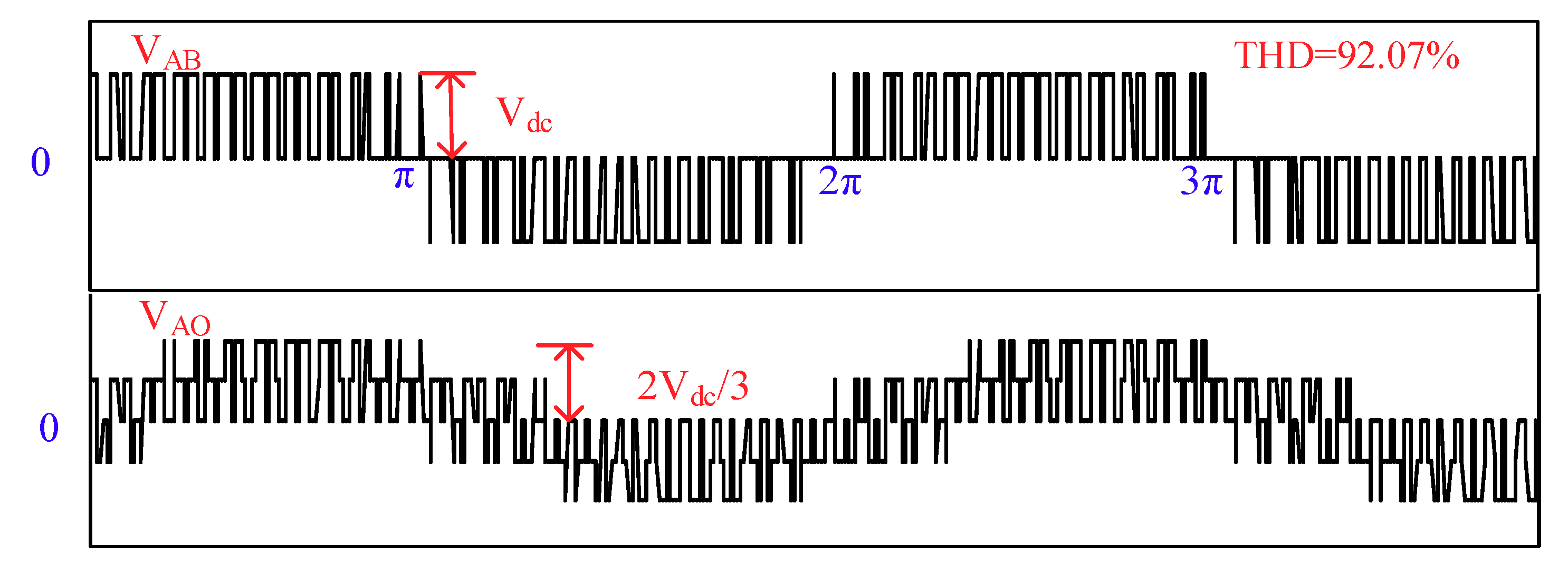
Generally, the DC/AC converter (inverter) is a piece of equipment for power conversion that is used to convert the DC input sources into an output AC voltage to feed AC loads. The inverters have a wide range of applications that satisfy the needs of the pre-mentioned industries. Based on the rating of the power electronics component as well as the control schemes, the process of operation of these inverters has been governed. Figure 1 shows the schematic circuit for the most famous three-level (3φ) inverter that is used to generate an output voltage waveform with a controllable magnitude and frequency. The output voltage waveforms for the line voltage VAB and phase voltage VAO are illustrated in Figure 2. Analytical study for the output voltage waveforms was performed to measure the level of the harmonics in the output waveform. Figure 3 displays the spectrum analysis of the line voltage waveform at different modulation index values [6].
The conventional three-level inverter has some drawbacks, which need solutions to be solved. First, in high and medium power applications, the inverter requires devices with high power ratings to withstand high currents and voltages. Therefore, many devices need to be connected in series/parallel strings to obtain the required voltage/current capacity, which leads to more costly and complex systems. Second, the low number of steps in the output voltage waveform generates an output power with poor quality where the harmonics content in the output waveform exceeded 90%. Thus, the output side should have passive filtering components of a large size. Third, a high level of switching losses is obtained, which, in turn, reduces the system efficiency. To overcome all these limitations, the conventional inverters were replaced with multilevel inverters (MLIs) in many industrial applications. MLIs have the following advantages:
1—MLIs introduce a high output voltage capability with no need for a step-up circuit.
2—Reduce power losses. As a result, MLIs score a high efficiency compared with conventional inverters.
3—The multiple steps in the output waveforms of the MLIs help in reducing the harmonic content. Therefore, the waveforms reach a sinusoidal shape.
4—Produce a lower electromagnetic interface (EMI).
5—The high number of steps in one cycle of the output voltage reduces the voltage stress on the switching devices, which gives the switching devices a long lifetime and enhances the system reliability.
6—The decrement in the level of harmonics content will lead to a decrement of (or even cancel) the size of the passive filter components in the system, which reduces both the cost and size.
All these features and more keeps the MLIs as the first choice of the consumers to meet the requirements of the industrial market.
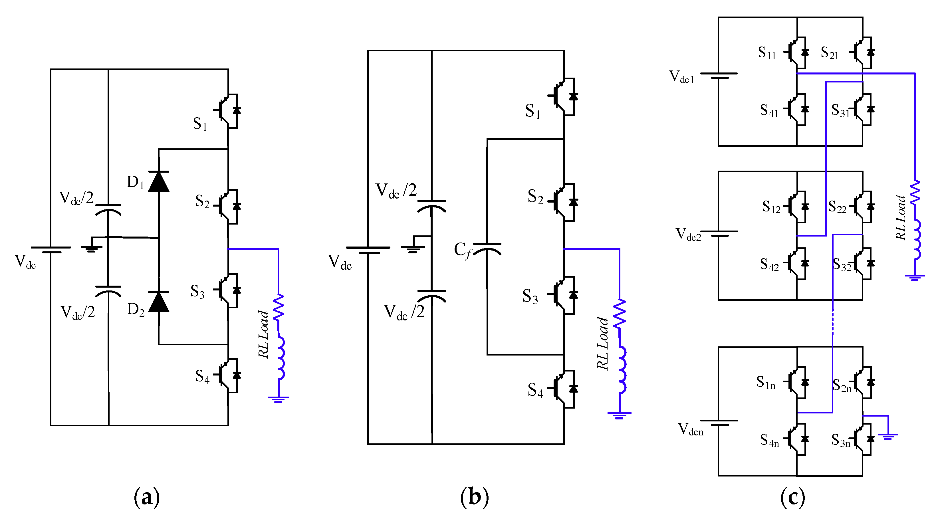
Basically, the conventional MLIs have been classified into three main topologies, as follows: Diode clamped MLIs topologies (DCMLIs) [7,8,9,10,11], flying capacitors MLIs (FCMLIs) [12,13,14], and cascaded H-bridge MLIs (CHBMLIs) [15,16,17,18,19,20]. Each topology has the ability to be extended to a high number of output voltage steps in the system expansion process. However, each topology has its own demerits.
DCMLIs require a set of different voltage ratings for clamping diodes. High voltage rating diodes are needed to block the reverse voltages. Moreover, in case of system expansion for more output power, extra switches, capacitors, and power diodes are required, which increases the system cost. Another disadvantage is that the real power flow is difficult due to the capacitor imbalance. Although the FCMLIs are still used in a large section of the industrial applications, they still have some disadvantages, which can be summarized as follows: FCMLIs need a large number of bulky and expensive capacitors that use a complex control scheme for voltage balancing. In addition, in the case of the real power transmission switching, utilization and efficiency are poor. Practically, the DCMLIs and FCMLIs are used sufficiently in systems with five levels in the output voltage waveforms, otherwise the system will be bulky and too complex to be controlled. On the other hand, in CHBMLIs, the system can be extended to any number of levels in the output voltage waveform. However, this will increase the number of components and DC suppliers in the system to meet the required level of power and number of steps in the output waveforms. In addition, the complex control scheme of capacitor voltage balancing still exists.
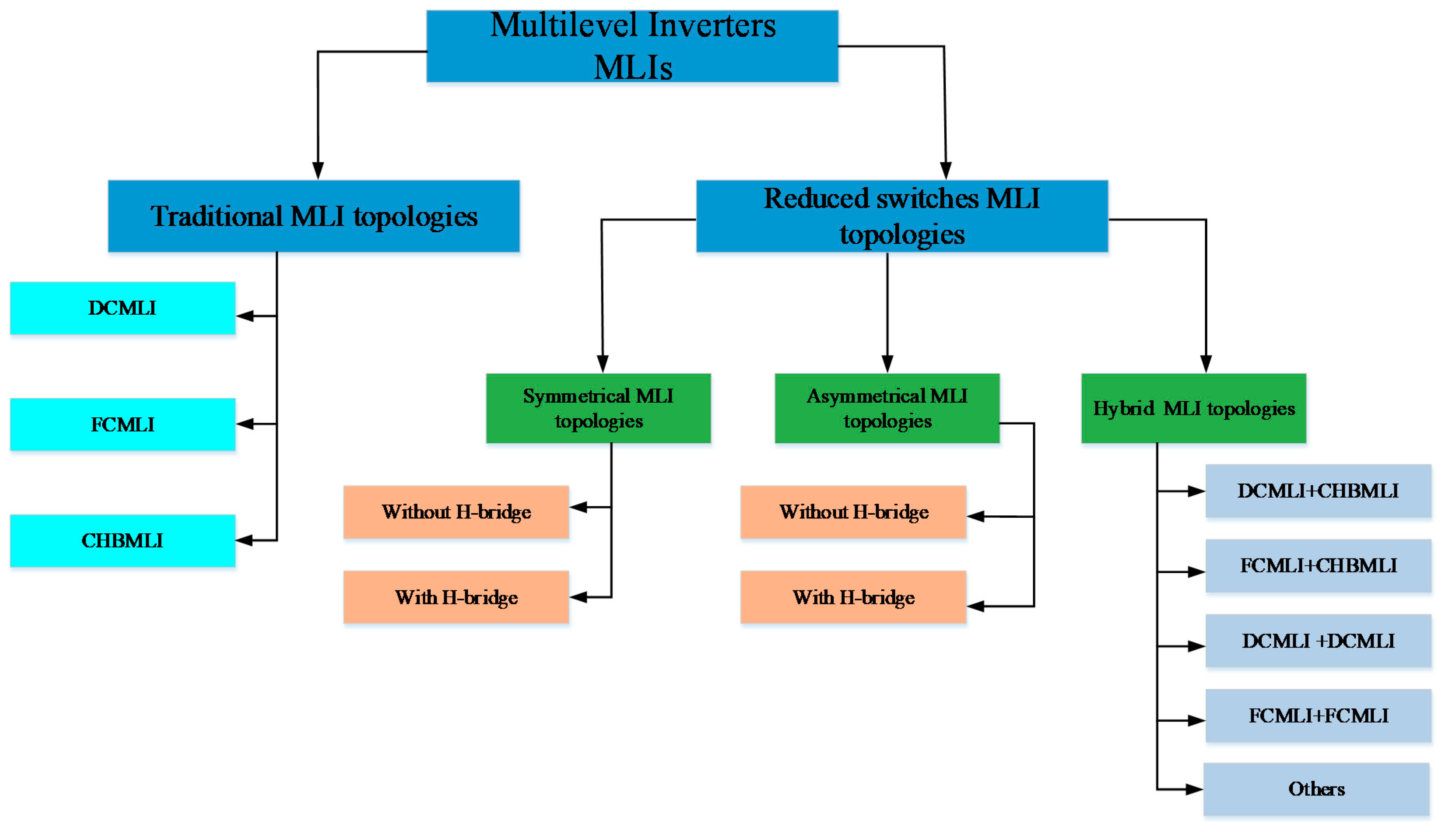
The main issues that face all the researchers in this field are to find the most optimum topology that uses a reduced number of components to establish the topology and achieve the desired number of levels. The recent MLIs topologies include the reduced components MLIs topologies, which can be divided into three main sections, symmetrical MLIs, asymmetrical MLIs, and hybrid MLIs topologies. Both the symmetrical and asymmetrical inverters are classified into topologies with an H-bridge unit as a polarity section and topologies without the H-bridge unit. In the hybrid systems two or more different units are connected in a cascade in order to increase the output levels and the power range with a reduced number of components.
This paper presents a survey for the different categories of the MLIs topologies taking into account the conventional and the newly invented topologies and highlights the features of each topology. Moreover, we find the optimum design of the MLIs from the presented topologies. The article also addresses some of the performance parameters that are used to distinguish between the different MLI topologies. This paper is organized as follows. Firstly an introduction of the definition and principle of operation of the MLIs has been presented, also the main members of the MLIs have been mentioned. In Section 2, a full description for the classical MLIs topologies has been presented. Also, the advantages and disadvantages are listed for each topology. Section 3 shows the newly presented MLI topologies and has been subdivided based on the structure of the MLIs topologies and the feeding system into three main categories; the Symmetrical MLIs, the Asymmetrical MLIs and the hybrid MLI topologies. As Modular Multilevel Converters MMCs represent a famous member in the Multilevel converters, a short description for the MMCs and the most common configurations for the submodules has been presented in Section 4. Section 5 presents a set of performance parameter expressions that have been defined, which are used to govern the level of reliability and discrimination in preference between different topologies. Finally, a conclusion of the paper is given in Section 6.

2. Conventional Multilevel Inverters

Figure 4 illustrates the classification of the MLIs members including traditional and reduced switches MLIs with different subsections. As mentioned before, the family of MLIs topologies is divided into three main branches: DCMLIs, FCMLIs and HBMLIs. They represent the conventional types of MLIs, as given in Figure 5. Although the conventional MLIs topologies scored great success, they still had some demisters that reduced their popularity. The following section describes different conventional MLIs to show the advantages and disadvantages of each topology.

2.1. Diode Clamped Multilevel Inverter Topology (DCMLI)

Figure 5a shows the DCMLI topology, which is used to generate an output voltage with three levels. The configuration for this topology contains four unidirectional power switches, two diodes, and two capacitors. The clamping diodes are connected in series to share the blocking voltage. Due to the different voltage stresses on the clamping diodes, diodes with different ratings are used in the same system to meet the required blocking voltage stress. For a long time this topology became a famous MLI that was used in industrial applications, especially in the medium and high power applications.
In the case of three- and five-level topologies of DCMLIs, the structure of the topology as well as the control scheme can be easily implemented. This topology needs only one DC supply regardless of the number of the levels in the output voltage waveform while the increase will be only in the number of chargeable capacitors as virtual DC suppliers in this topology [21]. On the other hand, DCMLIs have some drawbacks. For example, by increasing the number of levels over five levels, the complexity of the system will increase and the capacitor voltage balancing issue will require special treatment on the controlling scheme [15]. In addition, the process of system extending will require additional components, which will increase the system size and cost.

2.2. Flying Capacitor Multilevel Inverter (FCMLIs)

FCMLIs have the same structure as DCMLIs. However, the diodes are replaced with flying capacitors. Figure 5b shows the three-level FCMLI, which contains four unidirectional power switches and a flying capacitor, in addition to a DC supplier with two capacitors. The most famous structure of the FCMLI is the three and five level topology. The FCMLIs result in a level of voltages higher than that of the DCMLIs for the same number of output voltage steps, which make the system more reliable in the industrial applications [22]. Nevertheless, the bulky and large size capacitors are still the main drawbacks of this topology making it impossible to be packaged. Moreover, the system with output voltage levels higher than five levels have a complex control scheme for capacitor voltage balancing. In addition, high level of switching losses in the real power transmission are created [21].

2.3. Cascaded H-Bridge Multilevel Inverter (CHBMLIs)

Figure 5c presents the cascaded H-bridge MLI topology. CHBMLI was developed to overcome the drawbacks of the previous topologies and give the system more flexibility in high power ranges. The structure of this topology is based mainly on an HBU that contains four unidirectional power switches and one DC power supply. HBU is responsible for generating an output voltage with three levels (+Vdc, zero, and −Vdc). This unit can be repeated several times to achieve the desired level of output power. This topology has some advantages over the DCMLI and FCMLI, where it requires a reduced number of switching devices. Moreover, it is free of the capacitor’s charging and balancing problems. Furthermore, it achieves low switching losses because it eliminates both the flying capacitors and clamping diodes. CHBMLIs synthesize symmetrical units of HB or asymmetrical units to achieve an increment in the number of the steps in the output voltage waveforms.
The main drawbacks of the CHBMLIs are the high number of DC suppliers that should be used to feed the H-bridge units separately, as illustrated in Figure 5c, where PV panels act as DC supplies. This issue was solved by applying multi-winding isolated transformers to replace the isolated DC supplier [23,24]. In addition, CHBMLIs use low switching control schemes, which produces a high level of losses due to the transformer leakage. In the case of extending the number of components in the system, this will lead to a bulky and costly system. However, the CHBMLIs are still the best choice in many industrial applications, such as Static VAR compensation, electrical transmission systems (HVDC and EHVAC), energy conversion systems with grid integration like photovoltaic conversion systems, and wind energy conversion systems.
The advantages as well as the disadvantages of the different types of the conventional MLI topologies have been summarized in Table 1.
Generally, it can be concluded that the conventional MLIs have the basic idea of the multilevel process and still have many applications in the range of the medium and high power, including ship propulsion drive, rolling mills, blowers, compressors, and conveyors. The above-mentioned drawbacks motivated the researchers to look for new structures of MLIs to avoid these drawbacks. The following section presents the most newly MLI topologies, which were presented in the last two decades, taking into account the reduction of the components (DC suppliers, power switches, capacitors, diodes, etc.) that were used to build these topologies.

3. Reduced Components Multilevel Inverter

Recently, the research community focused on reducing the size and cost of MLI systems, which can be achieved by reducing the number of components. Many topologies have been introduced. The reduced-component topologies are classified into three categories, symmetrical MLI topologies, asymmetrical MLI topologies, and hybrid MLI topologies. Those MLIs aim to achieve a high number of output voltage steps and high efficiency.

3.1. Symmetrical Multilevel Inverter Topologies

The term symmetrical means that all the DC power supplies in this topology have the same value. The process of generating the output voltage is based on two stages, the level generating stage and polarity generating stage. Proceeding from this meaning, the symmetrical MLI topologies are divided into two types: symmetrical MLI topology with H-bridge and symmetrical MLI topology without H-bridge. The first type uses an HBU as a polarity part in the presented topology, which is responsible for directing the output voltage waveform and generating both halves. The second type does not need the polarity part. However, it depends on the generating level part to complete the waveform.

3.1.1. Symmetrical MLI with H-Bridge

Symmetrical MLI topologies are based on two parts, as follows. (1) Level generating part, which is used to generate different levels in the output voltage waveform based on the DC input sources and the switching devices. (2) Polarity generation part that consisted of an H-bridge. In most cases, the control scheme of these topologies uses the low switching frequencies to control the switches in the polarity part and the high switching frequencies for controlling the level generating part switches.
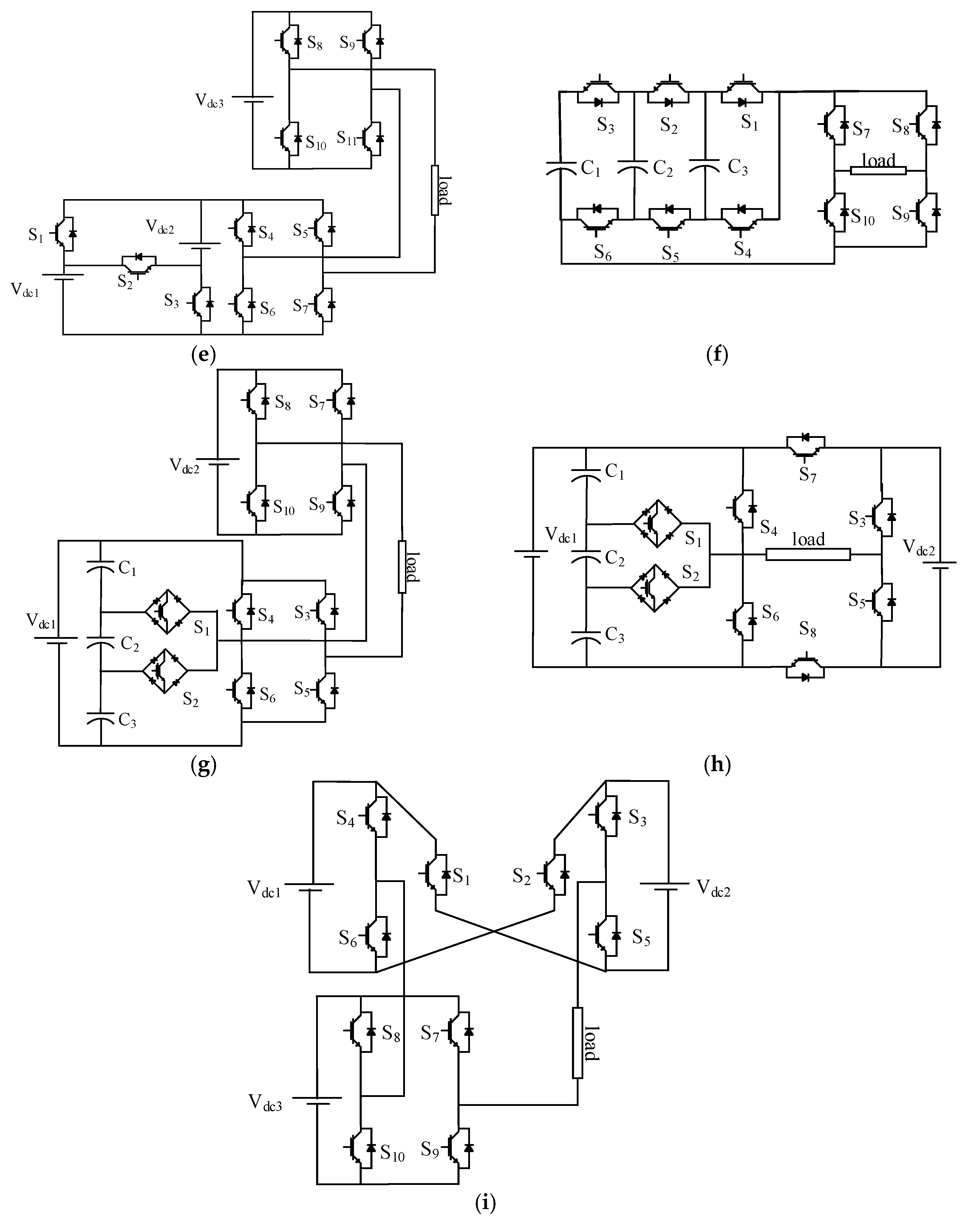
In [25,26], the authors presented new nine-level and eleven-level MLIs topologies, as shown in Figure 6a,b, respectively. The presented topologies contain the level generation and polarity generation parts. Those topologies are suitable for the renewable energy applications, especially in the PV farms, where multi-terminal DC supplies are required to feed these systems. A cascaded half-bridge-based multilevel DC link inverter was presented in [27,28]. This topology consisted of a set of half bridges that was connected in series and each half bridge had its own DC source as an input supplier and an H-bridge for polarity generating. This topology has a reduced number of switches to achieve the output voltage level compared with the conventional topologies, as illustrated in Figure 6c.
A developed cascaded cell based multilevel inverter was discussed by Ebrahim Babaei et al. in [29], as shown in Figure 6d. This topology presented a new basic unit for a cascaded multilevel inverter, where each unit cell consists of three DC sources and five unidirectional switches. Moreover, this topology supports the modularity process. Therefore, the output voltage of this system can be extended to an unlimited number of steps by adding units in cascaded connection. Compared with the conventional inverters, this topology has reduced count devices. In addition, it can be operated at the fundamental switching frequency.
A modification of the previous topology was presented in [30]. The authors used a set of bidirectional switches to connect the input sources with the polarity generation part and this structure is called the common emitter configuration. The topology presents a reduction in the number of components compared to the conventional topology. This topology has the ability to be extended to a high number of steps with the cascaded connection process. Figure 6e displays a topology configuration with an output of seven levels. In [31,32,33], the authors presented a new family of switched series/parallel DC suppliers MLIs based on symmetric voltage suppliers. These topologies consisted of a combination of switching devices that connected with the DC suppliers in a series/parallel ladder connection. The ladder connection of these topologies can be extended to fulfill the required level of output power by increasing the series/parallel combination. These topologies have the advantage of reduced capability of the blocking voltage and a reduced number of components compared to the conventional MLI topologies for the same number of output steps. This topology is illustrated in Figure 6f.
A modular symmetrical MLI is discussed in [34]. This topology consisted of a set of separate DC suppliers and a combination of free (insulated-gate bipolar transistor) IGBT diodes. The free diode IGBT was used to prevent the short circuit that might occur on the input side. This topology has fewer components compared to the conventional MLIs. However, the capacitors charging process is complex. Figure 6g displays a single-phase seven-level inverter. In Figure 6h, a similar topology is proposed [35]. The circuit structure consisted of a single source for charging a set of three capacitors. In addition, a combination of switching devices and diodes are employed in this topology to generate the output voltage.

3.1.2. Symmetrical MLI without H-Bridge

In the symmetrical MLI without H-bridge, the topologies do not need the polarity part in directing the different sides of the generated output voltage, and this mission is given to the generation level part. Therefore, this type of topology is based only on a single stage in the output voltage production.
A reduced switched bidirectional MLI, which consisted of a set of cells connected in series was presented in [36,37]. Each cell contained a separated DC supplier connected with four bidirectional switches, as illustrated in Figure 7a. The presented topology is connected in a cascade in case of increasing the output levels and extending the output power range. However, this topology has a high number of switches due to the usage of bidirectional switches, and this number of switches will increase in case of system expansion. In [38], an enhanced packed U-cells MLI (PUCMLI) topology was given, as shown in Figure 7b. The enhancement was based on using the unidirectional switches instead of the bidirectional with a small change in the topology structure. This change reduced the number of components in the topology while keeping the same number of the output steps. However, it still has drawbacks represented by the balancing circuit for capacitor voltage.
Figure 7c displays quite a similar topology [39,40], which is made of a modular of cells, each cell consists of a separate DC source and two unidirectional switches taking the shape of a ladder. This topology can be extended to any number of output steps by increasing the number of cells. In addition, in case of any malfunction in one of the cells, the topology can continue supplying the load but the number of the output levels and the voltage peak will be reduced. This topology is more suitable for renewable energy sources to make use of the equally separated DC suppliers, such as PV applications [41].
A cross-switched MLI is introduced in [42], as illustrated in Figure 7d. This topology ensures a reduced number of elements and the switches use low voltage. A modification of the previous topology was introduced by Banaei et al. [43]. The system presented a cascaded multilevel inverter to improve the systems performance parameters. This topology succeeded in reducing the peak inverse voltage (PIV) of the switches and increased the switch’s lifetime. Consequently, the performance of the system was improved. Moreover, the presented topology could be extended by repeating the modular stage several times, as given in Figure 7e. A Single-phase T-Type inverter was investigated in [44]. The circuit was implemented based on different kinds of power switches, such as Si IGBT, SiC MOSFET, and GaN HEMT at 600 V blocking voltage range. The study compared different switches based on the efficiency and total harmonic distortion (THD) of the output waveforms.

3.2. Asymmetrical Multilevel Inverter Topologies

In the symmetrical MLIs in the previous section, each DC supplier is responsible for a single level in the output waveform. As a result, a high number of DC sources are required in the case of high output steps. The DC supplier is considered the most expensive equipment in the power system. Therefore, the system will be more expensive. In order to overcome this limitation, the asymmetrical MLI topologies were presented. The asymmetrical topologies synthesize a set of input DC sources with different magnitudes to keep the number of DC sources as optimal as possible. The implementation of the asymmetrical MLI topologies can be achieved as follows.
  • Change topologies from symmetrical into asymmetrical by replacing the symmetrical DC suppliers with asymmetrical suppliers while keeping the structure of the topology unchanged.
  • In other cases, the asymmetrical topologies were implemented by repeating the basic cell with different values of the input DC suppliers based on binary or trinary sequence.
  • Change the structure of the symmetrical topology to be compatible with the asymmetrical feeding suppliers.

3.2.1. Asymmetrical MLI Topologies with H-Bridge

The asymmetrical MLI topologies are divided into two main sections based on the structure of the topology; asymmetrical MLI topologies with H-bridge and asymmetrical MLI topologies without H-bridge.
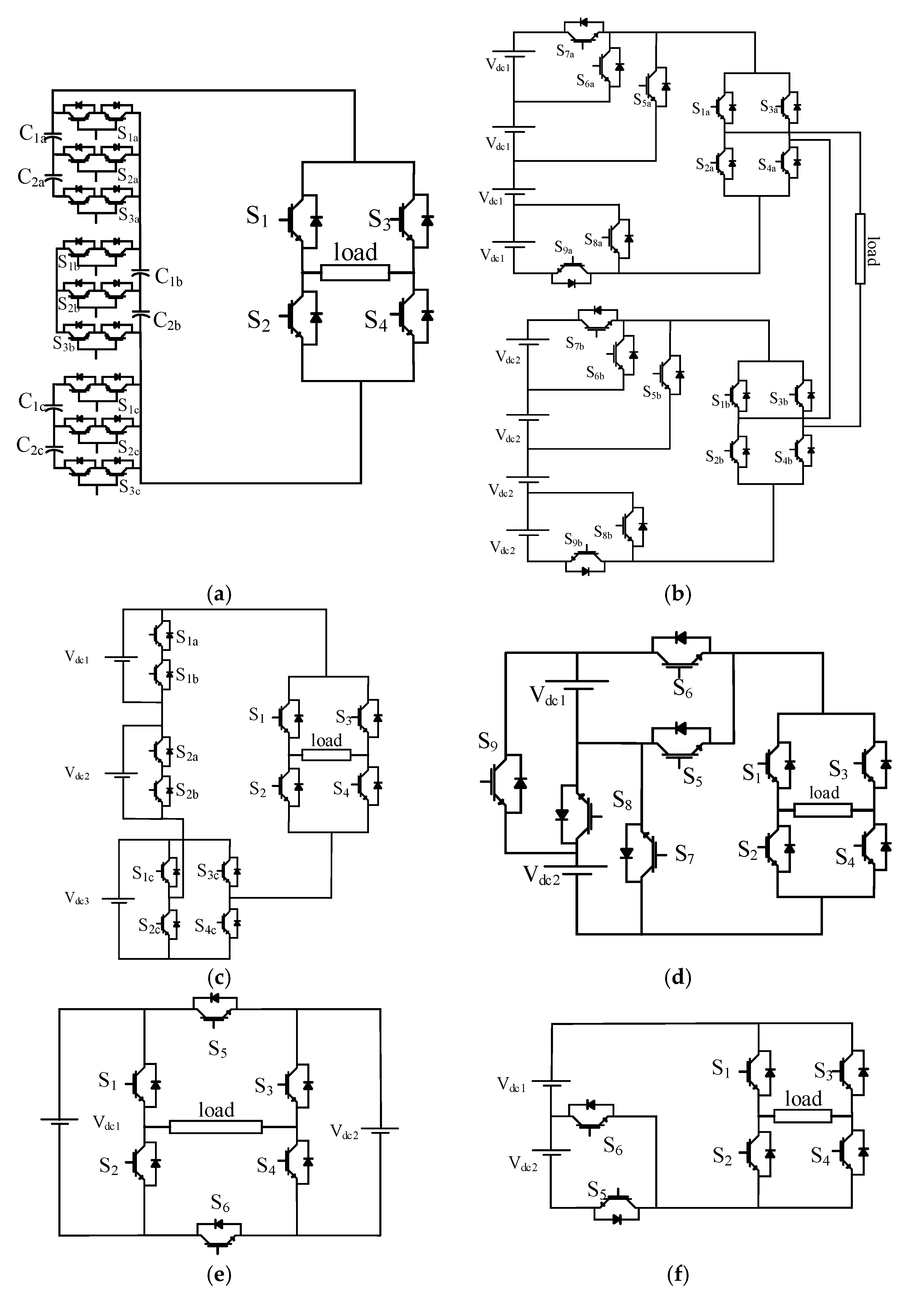
The cascaded MLI topology that was presented in the symmetrical section [28], is modified to asymmetrical topology [45]. This structure uses different magnitudes of input voltages. This modification in the topology affects the flexibility of the system and its application. In addition, compared to the conventional topologies, the asymmetrical topology ensures a minimum number of components, which keeps the cost as low as possible. Moreover, this topology has the ability to be extended to a high number of output steps. In [46], the authors presented a multilevel module (MLM). As shown in Figure 8a, the structure is performed by connecting a set of basic unit cells, where each basic cell had two sources to produce an output voltage with three levels. Moreover, the structure can be extended by series connection of the basic cells to achieve the required amount of output power. However, the capacitor voltage balancing will be more complex. Furthermore, the authors presented different case studies that discussed the optimal operation based on the optimal number of switching devices and gate drives.
In [47,48], the authors introduced a set of cascaded sub multilevel cells to build up the asymmetrical MLI topologies, which can operate under the symmetrical and asymmetrical MLI classification based on the magnitude of the feeding sources. Compared to the conventional CHBMLIs, the number of switches was reduced for the same number of steps in the output voltage waveforms, as given in Figure 8b. On the other hand, the total standing voltage of this topology is higher than the recorded value for the conventional CHB.
Figure 8c illustrates a topology that is made up of two half bridges connected in series with an H-bridge unit [49,50]. Thus, the given structure is closer to a hybrid configuration than the asymmetrical configuration. The proposed topology presents a reduction in the number of switching devices compared to the other conventional topology. In [50], three different algorithms are presented in order to estimate the most optimal values for the magnitudes of the DC input sources. In [51,52], the authors designed a topology to reduce the switching devices, as shown in Figure 8d. In addition, it can be extended to a high number of steps by adding multi-sources and switches with a trinary sequence of DC sources. Moreover, it has the ability to operate with both fundamental and higher switching frequency.
A new structure with a developed H-bridge is presented to ensure a reduced number of components, low blocking voltage on the switches, which makes the topology easier to be implemented, low cost, and high reliability [53,54]. The proposed topology can be extended into a high number of voltage steps either in a cascaded connection, or extending the same topology with multi DC suppliers and switching devices. Figure 8e presents the basic cell for the proposed topology, which consisted of two DC suppliers and six unidirectional power switches. A similar topology that contains a set of two DC suppliers and six unidirectional switches is presented in [55]. However, it has a different arrangement of components, as displayed in Figure 8f. This combination is valid for both symmetrical and asymmetrical configurations. In addition, this topology has two scenarios for expanding in either the cascaded connection mode or modular mode. This topology has been studied under five different algorithms for choosing the values of the DC suppliers.
In Figure 8g, a transformer based MLI is presented [56]. This topology synthesizes a single DC source, multi-terminal high switching frequency transformer, and a combination of unidirectional and bidirectional switches to generate the output voltage waveforms. This topology uses a single DC source. However, the transformers generate spikes in the output waveforms, increase the losses, and have a high cost, in addition to the bulky structure and unpackaged inverter circuit.

3.2.2. Asymmetrical MLI without H-Bridge

These kinds of topologies are the most famous among different categories of the MLI. The main target of those topologies is to obtain the optimum number of components to generate a certain number of steps in the output voltage waveform, and also to improve the quality of the output voltage performance and increase efficiency. These topologies synthesize these components to generate the desired output voltage waveform without any need for the polarity generating section in each topology. The input DC suppliers can be used in a trinary sequence, binary sequence, or any random sequence that serves to generate the desired number of steps in the output waveform.
Figure 9a shows the basic cell of an asymmetrical MLI system with reduced number of components to generate an output voltage with seven steps [57]. The topology has two sources and six switches and can be extended to a high number of steps in the output voltage waveform by adding additional switches and DC suppliers. A Square T-type (ST-Type) Module MLI is presented in [58], as illustrated in Figure 9b. Based on 4 unequal DC sources and 12 unidirectional switches, this configuration generates an output voltage with 17 steps. The output voltage steps can be extended by connecting more than one unit in a cascaded connection. Not only will the output power range be increased but also the level of harmonics content will be reduced due to the increase in the output voltage steps.
Modified multilevel inverters with reduced structures based on packed U-cells are presented in [59,60]. The basic cell of the proposed topology uses six unidirectional switches and two DC sources, as displayed in Figure 9c. The expansion of this topology can be performed by a cascaded connection between the basic cell, or increasing the arrangement of the DC suppliers and switches in the same cell. The proposed topology presents a reduced number of components and low voltage stress on the switches.
Siddique et al. presented a new asymmetrical MLI topology with reduced switch count [61]. The proposed inverter presented an optimum design of the number of DC voltage sources and switching devices. In addition, the modularity process for a high number of steps generation at the output voltage was supported. Moreover, the authors introduced a generalized structure of the proposed topology for expanding the topology to a high power level. Figure 9d shows the basic cell, which consisted of three asymmetrical DC suppliers and a set of eight switches that were put in a special arrangement. Similarly, the authors presented an asymmetrical MLI topology with optimum design [62]. The basic unit of this topology, as given in Figure 9e, consisted of ten switches and three DC suppliers to generate an output voltage with 15 steps. Moreover, this topology can by expanded regularly by adding two switches for any additional DC source.
An envelope type (E-Type) module consisting of four unequal DC suppliers and ten switches to generate an output voltage with 13 steps is presented in [63]. The proposed system supported modularity by connecting multiple units in a cascaded connection. Figure 9f shows the configuration of the E-Type MLI topology. Two different configurations of K-Type MLI topology are investigated in [64,65], as shown in Figure 9g,h, respectively. Both types presented self-balance methods for the capacitors charging and ensured a capacitor balancing process without any additional charging or balancing circuits. In addition, both topologies supported modularity to increase the output power range and reduced the harmonics content in the output voltage waveforms.

3.3. Hybrid Multilevel Inverter Topologies

The term “hybrid system” indicates that the presented system contains two or more different topologies in the same system that are connected to each other in a series connection in order to increase the range of the output power and reduce the number of components in the system to get a better performance and high efficiency. The hybrid system might be a combination of the following. (1) The conventional MLIs that were presented in the first section of this paper. (2) A combination of two (or more) units from the pre-discussed topologies (symmetrical or asymmetrical MLI topologies) to achieve the desired target.
In [66], the authors introduced a hybrid system for a symmetric MLI that consisted of a switched-capacitor MLI unit and a floating-capacitor MLI unit, which is integrated into two isolated sub-units and connected in a cascaded connection form, as illustrated in Figure 10a. The proposed system presents an output voltage with 19 steps, which reflects a reduction in the power losses and enhancement in the overall efficiency. Abarzadeh et al. [67], discussed a hybrid MLI system that consisted of a combination of voltage-level multiplier modules (VLMMs) in series with a hybrid-neutral point-clamped (HNPC) unit. In addition, the authors proposed a novel switching control, which achieves a self-balancing of all the capacitors voltage. Moreover, the odd multiples of switching frequency were eliminated from the output voltage frequency spectrum. This topology can be extended by repeating the VLMM unit several times. Figure 10b shows the two cascaded units of the proposed topology. On the other hand, the same authors presented an improved active neutral point clamped hybrid system, which contains a combination of a flying capacitor (FC) MLI unit in series with an active-neutral-point-clamped (ANPC) unit [68,69]. The system generates an output voltage with 11 steps and ensures a reduced number of high-frequency switches, which in turn, reduces the losses and costs. In addition, the proposed control strategy in the work presents a self-balancing for the capacitors in the FC unit. Consequently, the cost, size, and the reliability parameters of the system are enhanced. Figure 10c presents the hybrid system. Lee et al. [70] proposed an innovative symmetrical four-level submodule as a basic cell that has a cascaded connection with an H-bridge unit to generate an output voltage with nine steps. This system presented a high number of steps in the output voltage waveform. However, it used four isolated DC suppliers, which increased the cost and size. The nine-level hybrid cascaded MLI is shown in Figure 10d. A hybrid system, which consisted of an H-bridge unit and a switched series/parallel MLI unit, is presented in [31]. The number of steps in the output voltage waveform is determined based on the number of stages of the switched series/parallel MLI unit. In addition, this work discussed configurations for 11-level (given in Figure 10e) and 15-level hybrid systems. However, the system presented a modular and hybrid system but the system needed many isolated DC suppliers, which increased the system cost.
A combination of a half bridge MLI, a full bridge MLI, and a DCMLI unit is given in [68]. The proposed topology increased the flexibility of the system by producing a high number of steps in the output voltage. In [71], a combination of an improved FC unit cascaded with an H-bridge unit is used to form a hybrid MLI system, as shown in Figure 10f. The proposed topology supports modularity, which increases the number of steps in the output voltage. Moreover, this topology is a good choice for high power applications. A T-Type MLI unit and an H-bridge unit are combined in a hybrid system, as presented in [72]. This configuration can be extended to any number of steps by extending the T-Type unit. The basic cell for the combination is presented in Figure 10g. The proposed structure is simple, ensures a reduced number of components, and presents a high efficiency due to the low power losses. A modification of the previous hybrid system is given in [73]. The proposed topology involves the H-bridge unit with the T-Type unit in order to produce a compact topology with a reduced number of components, and thus can be packaged. The topology presents an output with nine steps and the output can be extended by modulating the T-Type unit and increasing the capacitors’ stages or cascading the same unit several times. The second scenario for system extending has been discussed in the reference. Figure 10h presents the improved topology.
A 21-level MLI hybrid system that consisted of a combination of a cross-switched MLI unit cascaded with an H-bridge unit is investigated in [74]. The proposed topology ensures an increment in the output voltage steps, decrement in the number of components that are synthesized in this hybrid system compared to the conventional topologies, and leads to a reduction in the losses due to the usage of the low frequency modulation technique. The structure of the proposed hybrid system is illustrated in Figure 10i.
Finally, it can be summarized that the MLIs topologies are multiple and have different characteristics, and each topology has its advantages and disadvantages, which are used to differentiate between those different types and choose the appropriate type for each of the different applications. The advantages and disadvantages for the different topologies of MLIs which presented in this section have been summarized in Table 2. Taking into account the different categories which were previously divided.

4. Modular Multilevel Converters (MMC)

Modular multilevel converter (MMC) is one of the most important members of the DC/AC converter family, especially in the industrial market due to the good features that these kinds of converters present. For example, the high and medium power energy conversion capability especially in the high-voltage direct current (HVDC) applications. It also presents a high number of output voltage steps, which in turn enhances the system efficiency and low voltage stress on the power switches due to the fact that the low-voltage ratings of these power switches are stacked up in the MMC.
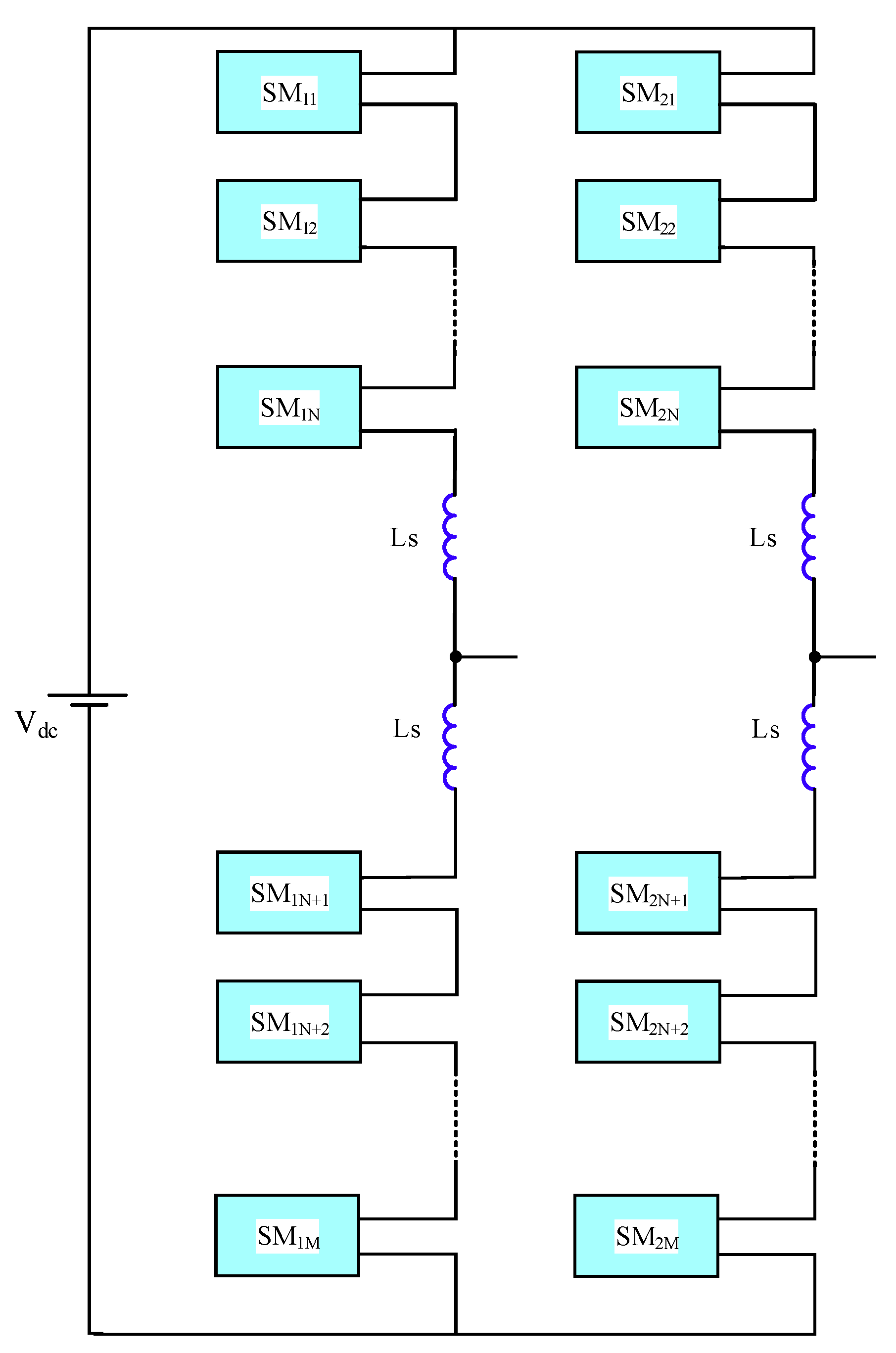
Schematically the MMC consisted of two arms for each leg and each leg has an N number of submodules (SM)s connected in series to serve the purpose of the required level of output power. Also, a series inductor Ls has been connected in each arm for the purpose of dv/dt suppression. Also, it prevents the high-frequency components in the output current from injecting into the load. The general configuration for a single-phase MMC system has been presented in Figure 11. The structure of the MMC circuit is almost fixed and the change is in the shape of the SM cell that was used to build up the MMC. The common SMs forms that were presented for the MMC have been illustrated as follows:
(1)
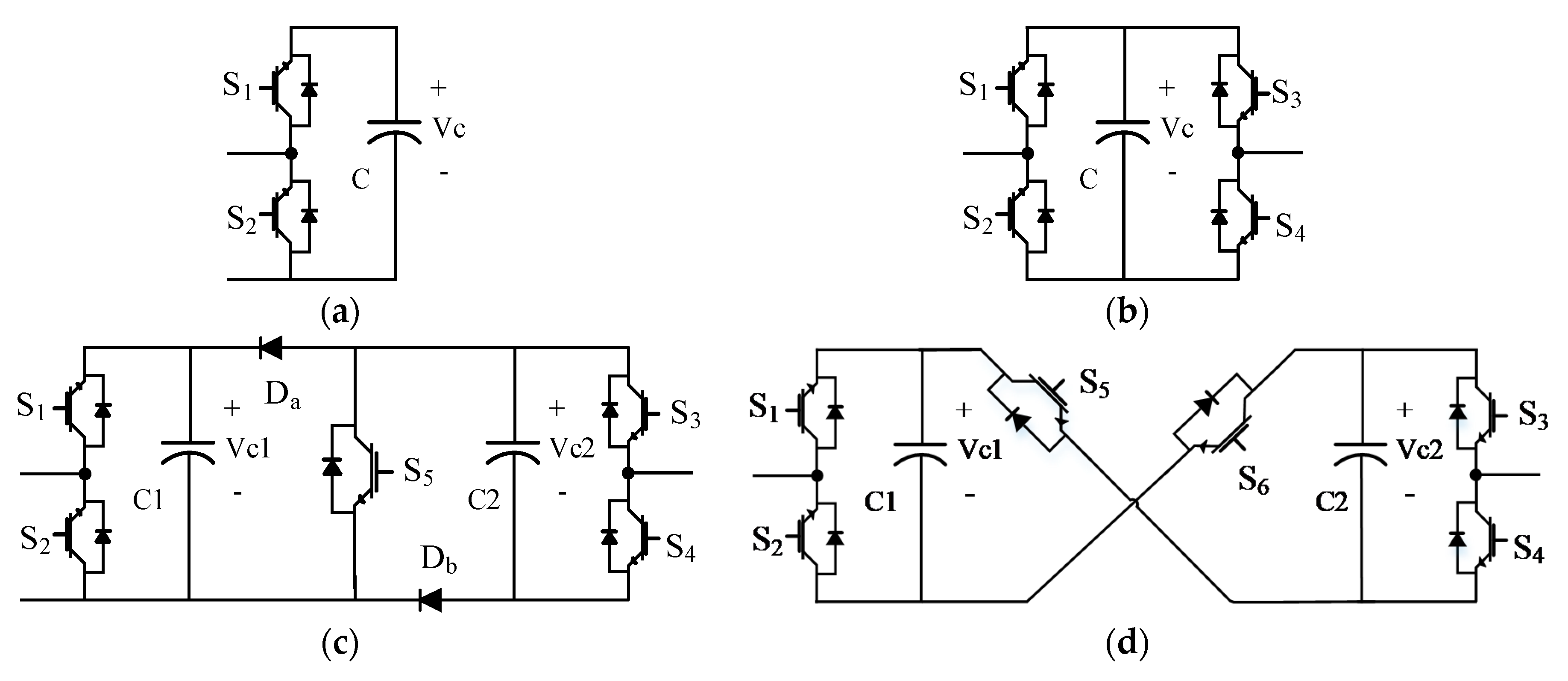
The half-bridge submodule circuit [75]: the SM unit configuration circuit has been illustrated in Figure 12a. It basically consisted of two power switches and a capacitor acted as a power source in parallel with the switches. The output voltage of this basic cell could be equal to the capacitor voltage in the case of firing the switch S1 ON, or zero if S2 is in the ON state. So, the switches S1and S2 operate complimentarily.
(2)
The full-bridge submodule circuit [76]: another configuration for the SM in the MMCs is the full bridge. The basic cell of the full-bridge SM consisted of four switching devices and capacitors arranged in the form of a bridge, this arrangement is presented in Figure 12b. Every two switches in the same arm of the basic cell operate complimentarily.
(3)
The clamp-double submodule circuit [77]: the configuration represented by two half-bridge units that connected back to back with an additional two diodes and a power switch in the middle, as shown in Figure 12c.
(4)
The three-level converter submodule circuit [78]: the configuration for this SM is the same as the configuration of the three-level NPC circuit and the three-level FC circuit, which is presented in Figure 5a,b, respectively. The output voltage waveform from this unit is a three-level output voltage (0, Vc1, Vc1 + Vc2).
(5)
The five-level cross-connected submodule circuit [79]: the configuration of this SM consists of two half-bridge cells back to back and in between, there are two power switches in the cross direction. The structure of this SM is presented in Figure 12d. Based on the title of this SM the output voltage contains five levels (0, Vc1, Vc2, Vc1 + Vc2).
(6)
A comparison has been held between the different SMs to differentiate between them. This comparison takes into account the number of components for each SM unit, the number of levels in the output voltage waveform each cell, and the size of the output losses in the SM unit. The comparison between the different structures for the SMs is presented in Table 3.

5. Performance Parameters of the Compared MLI Topologies

The percentage of reliability of each MLI topology is measured based on its contribution in reducing the performance parameters values to the optimum values. These parameters are represented in the optimum number of components per pole, the average number of components per pole, the total standing voltage, system efficiency, THD, and circulating current, etc. This section presents a full description of performance parameters supported with the mathematical formulas for each parameter individually.

5.1. Total Number of Components per Pole

This parameter is discussed in [25,80]. It is defined as the total number of components per pole that is used to generate the desired number of levels in the output voltage waveform. The benefit of calculating this parameter is to get the most economical topology, which uses a reduced number of components, and thus reduces the overall cost of the system. This parameter is calculated by:
N C o m / L e v = N S u p + N C a p + N T r a n + N S w + N D + N A u x N p o l e s
where:
  • NCom/Lev: Number of components per pole for each level in the output voltage waveform.
  • NSup: Number of DC power suppliers that were used to feed the topologies.
  • NCap: Number of capacitors in the proposed topology.
  • NTran: Number of transformers.
  • NSw: Number of switching devices.
  • ND: Number of diodes in the converter circuit.
  • NPoles: Number of levels in the voltage waveform per pole.
  • NAux: Any auxiliary components in the converter circuit.
It should be noted that this parameter can be calculated for any of the pre-discussed topologies.

5.2. Average Active Switches per Pole

In order to get more accurate results for the proposed topologies, the average active switches per pole can be calculated. This parameter can be defined as the summation of the active switches for each level of the output voltage waveform divided by the number of poles in the output voltage waveform, as follows.
N A v g / p o l e = i = 0 m N s w ( i ) N p o l e s
where Nsw(i) represents the number of active switches in the proposed topology in the period of generating a certain level. This parameter can enhance the reliability and overall efficiency because of the reduction in the switching losses [25].

5.3. Total Standing Voltage

This parameter is the summation of all the blocking voltages capability for all the switches in a certain topology [46]. Equation (3) describes this parameter.
T S V = i = 1 n V S i
where n is the number of switching devices in a certain topology and VSi is the blocking voltage of different switches. For example, considering the presented topology in [62] as an asymmetrical MLI without H-bridge, the blocking voltage of different switches can be given as follow:
VS1 = VS2 = Vdc
VS3 = VS4 = 6Vdc
VS5 = VS6 = 6Vdc
VS7= VS8 = Vdc
VS9 = 3Vdc
Therefore, the total standing voltage for this topology is calculated as follows:
TSV = 2 (1 + 6 + 6 + 1 + 3) Vdc = 2 × 17 = 34 Vdc

5.4. Total Harmonic Distortion (THD)

Harmonics are defined as the components with multiple integers of the fundamental frequency that were added to the fundamental components and it distorts the output waveform shape. The value of the THD indicates how close the output voltage waveform of the MLI circuit is to the pure sinusoidal waveform. THD is formulated as the root of the summation of the squares of all the harmonics components in the output waveform divided by the fundamental component [81]. The value of the THD in each waveform can be calculated based on the following formula:
T H D = n = 2 V n 2 V 1
where n represents the different harmonics’ orders in the waveform and V1 is the fundamental component of the waveform. The value of the THD depends on the control scheme and number of steps in the output waveform.

5.5. Overall Efficiency

The overall efficiency of any system represents the percentage of the consumed power on the output terminals to the input power. The efficiency can be kept high if the power losses through the proposed system are low. The general formula for calculating the system efficiency is presented as follows:
η = P o u t P i n = 1 P l o s s e s P i n = v r m s i r m s V d c I d c
where Vrms and irms are the load voltage and load current, respectively. Vdc and Idc are the input voltage and input current, respectively. The efficiency of any MLI system is highly affected by the controlling method and the number of the steps in the output waveforms.

5.6. Circulating Current

The circulating current is one of the most important parameters that need to be detected in the MLI system. The circulating current in the MLIs is simply defined as the current component between the neutral point of the load and supply ground. The circulating current is the cause of parasitic capacitance, shaft voltage, and bearing damage. In addition, it causes an increment in the electromagnetic interference (EMI) level. Therefore, reducing this current is highly recommended in the MLI system [82]. Moreover, this current has a harmful effect on the power electronics components and could cause a malfunction to these components [83]. The effect of the circulating current can be limited by using the PWM control techniques to the level of ±Idc/2, ±Idc/3 and ±Idc/6, such as phase disposition (PD) [84], phase opposition disposition (POD) [85], alternative phase opposition disposition (APOD), and phase shift (PS) [86,87].
Some of the performance parameters have been applied for the presented MLI topologies to choose the most optimal design from the compared structures that achieve the minimum values from the tested parameters. The configuration parameters and the performance parameters have been presented in Table 4. The performance parameters have been calculated for almost all of the presented topologies based on the equations that are presented in the description of this section. For the performance parameters, some of the statistics that are presented in Table 3 have been mentioned in the references, such as the THD and the TSV, and are collected in the table. Other performance parameters (NCom/Lev and Navg/pole) have been calculated from the formula given previously, as well as the data given for each structure in the table. As mentioned before that the parameter NCom/Lev has been calculated to determine the number of components per level, this parameter is used to detect the most economical structure. On the other hand, the parameter Navg/pole is used to detect the average number of active components per pole, and this parameter is useful in detecting the size of losses in the MLI structure. Therefore, the smaller the calculated values of these parameters, the better the performance of this MLI topology.

6. Conclusions

MLI topologies caused a revolution in the industrial community because of the smart features over the conventional inverters. MLIs became widely used in the low, medium, and high power industrial applications. Many research teams proposed different structures of the MLIs topologies in order to achieve a reduced number of components, gain a high efficiency with low cost, and obtain a high number of steps in the output waveforms. This paper discussed some of the MLI topologies that were presented in the last two decades and reported different features of each topology, such as the basic structure and number of steps in the output waveforms. In addition, the newly invented MLI topologies were discussed in brief and classified into three main categories: symmetrical, asymmetrical, and hybrid topologies. The symmetrical and asymmetrical topologies were divided into two types, as follows: (1) Topologies that used a polarity generating section were called MLIs with H-bridge. (2) Topologies that did not need the polarity section generating were called MLIs without H-bridge. Moreover, performance parameters were discussed. These parameters are used to obtain the optimum number of components and achieve a reliable topology. Due to the high number of steps in the output waveforms in MLIs, a low rating for the power switches compared to the conventional inverters can be applied. Moreover, the voltage stress on the switches is reduced, and thus increases the lifetime and percentage of reliability of the switching devices. Furthermore, the reduced count of components (especially the DC suppliers) made the size and volume smaller. As a result, the system became more packable and achieved a low cost.

Author Contributions

A.H. conducted the review and wrote the manuscript, M.A.H. check the manuscript grammarlly and help in enhancing the quality of the manuscript. X.Y. and W.C. Guided and contributed in discussions and supervision. All authors have read and agreed to the published version of the manuscript.

Funding

This research received no external funding.

Conflicts of Interest

The authors declare no conflict of interest.

References

  1. Prabaharan, N.; Palanisamy, K. A comprehensive review on reduced switch multilevel inverter topologies, modulation techniques and applications. Renew. Sustain. Energy Rev. 2017, 76, 1248–1282. [Google Scholar] [CrossRef]
  2. Kala, P.; Arora, S. A comprehensive study of classical and hybrid multilevel inverter topologies for renewable energy applications. Renew. Sustain. Energy Rev. 2017, 76, 905–931. [Google Scholar] [CrossRef]
  3. Jahns, T.M.; Blasko, V. Recent advances in power electronics technology for industrial and traction machine drives. Proc. IEEE 2001, 89, 963–975. [Google Scholar] [CrossRef]
  4. Kaboli, S. Reliability in Power Electronics and Electrical Machines: Industrial Applications and Performance Models; IGI Global: Hershey, PA, USA, 2016. [Google Scholar]
  5. Zhang, G.; Li, Z.; Zhang, B.; Halang, W.A. Power electronics converters: Past, present and future. Renew. Sustain. Energy Rev. 2018, 81, 2028–2044. [Google Scholar] [CrossRef]
  6. Wu, B.; Narimani, M. High-Power Converters and AC Drives; John Wiley & Sons: Hoboken, NJ, USA, 2017. [Google Scholar]
  7. Yuan, X.; Barbi, I. Fundamentals of a new diode clamping multilevel inverter. IEEE Trans. Power Electron. 2000, 15, 711–718. [Google Scholar] [CrossRef]
  8. Newton, C.; Sumner, M. Novel technique for maintaining balanced internal DC link voltages in diode clamped five-level inverters. IEE Proc.-Electr. Power Appl. 1999, 146, 341–349. [Google Scholar] [CrossRef]
  9. Pan, Z.; Peng, F.Z.; Corzine, K.A.; Stefanovic, V.R.; Leuthen, J.M.; Gataric, S. Voltage balancing control of diode-clamped multilevel rectifier/inverter systems. IEEE Trans. Ind. Appl. 2005, 41, 1698–1706. [Google Scholar] [CrossRef]
  10. Shukla, A.; Ghosh, A.; Joshi, A. Control schemes for DC capacitor voltages equalization in diode-clamped multilevel inverter-based DSTATCOM. IEEE Trans. Power Deliv. 2008, 23, 1139–1149. [Google Scholar] [CrossRef]
  11. Marchesoni, M.; Tenca, P. Diode-clamped multilevel converters: A practicable way to balance DC-link voltages. IEEE Trans. Ind. Electron. 2002, 49, 752–765. [Google Scholar] [CrossRef]
  12. Peng, F.Z.; Lai, J.-S.; McKeever, J.W.; Van Coevering, J. A multilevel voltage-source inverter with separate DC sources for static var generation. IEEE Trans. Ind. Appl. 1996, 32, 1130–1138. [Google Scholar] [CrossRef] [Green Version]
  13. Escalante, M.F.; Vannier, J.-C.; Arzandé, A. Flying capacitor multilevel inverters and DTC motor drive applications. IEEE Trans. Ind. Electron. 2002, 49, 809–815. [Google Scholar] [CrossRef]
  14. Lin, B.; Huang, C. Analysis and implementation of a single-phase capacitor-clamped inverter with simple structure. IEE Proc.-Electr. Power Appl. 2004, 151, 555–562. [Google Scholar] [CrossRef]
  15. Rodriguez, J.; Lai, J.-S.; Peng, F.Z. Multilevel inverters: A survey of topologies, controls, and applications. IEEE Trans. Ind. Electron. 2002, 49, 724–738. [Google Scholar] [CrossRef] [Green Version]
  16. Peng, F.; McKeever, J.; Adams, D. Cascade multilevel inverters for utility applications. In Proceedings of the IECON’97 23rd International Conference on Industrial Electronics, Control, and Instrumentation (Cat. No. 97CH36066), New Orleans, LA, USA, 14 November 1997; pp. 437–442. [Google Scholar]
  17. Corzine, K.; Familiant, Y. A new cascaded multilevel H-bridge drive. IEEE Trans. Power Electron. 2002, 17, 125–131. [Google Scholar] [CrossRef]
  18. Rodríguez, J.; Bernet, S.; Wu, B.; Pontt, J.O.; Kouro, S. Multilevel voltage-source-converter topologies for industrial medium-voltage drives. IEEE Trans. Ind. Electron. 2007, 54, 2930–2945. [Google Scholar] [CrossRef]
  19. Tolbert, L.; Peng, F.Z.; Cunnyngham, T.; Chiasson, J.N. Charge balance control schemes for cascade multilevel converter in hybrid electric vehicles. IEEE Trans. Ind. Electron. 2002, 49, 1058–1064. [Google Scholar] [CrossRef] [Green Version]
  20. Tolbert, L.M.; Peng, F.Z.; Habetler, T.G. Multilevel inverters for electric vehicle applications. In Proceedings of the Power Electronics in Transportation (Cat. No. 98TH8349), Dearborn, MI, USA, 22–23 October 1998; pp. 79–84. [Google Scholar]
  21. Colak, I.; Kabalci, E.; Bayindir, R. Review of multilevel voltage source inverter topologies and control schemes. Energy Convers. Manag. 2011, 52, 1114–1128. [Google Scholar] [CrossRef]
  22. Chen, A.; He, X. Research on hybrid-clamped multilevel-inverter topologies. IEEE Trans. Ind. Electron. 2006, 53, 1898–1907. [Google Scholar] [CrossRef]
  23. Suresh, Y.; Panda, A.K. Investigation on hybrid cascaded multilevel inverter with reduced dc sources. Renew. Sustain. Energy Rev. 2013, 26, 49–59. [Google Scholar] [CrossRef]
  24. Panda, A.K.; Suresh, Y. Research on cascade multilevel inverter with single DC source by using three-phase transformers. Int. J. Electr. Power Energy Syst. 2012, 40, 9–20. [Google Scholar] [CrossRef]
  25. Ali, A.I.; Sayed, M.A.; Mohamed, E.E.; Azmy, A.M. Advanced Single-Phase Nine-Level Converter for the Integration of Multiterminal DC Supplies. IEEE J. Emerg. Sel. Top. Power Electron. 2018, 7, 1949–1958. [Google Scholar] [CrossRef]
  26. Hassan, A.M.; Yang, X.; Ali, A.I.; Ahmed, T.A.; Azmy, A.M. A Study of Level-Shifted PWM Single-phase 11-Level Multilevel Inverter. In Proceedings of the 2019 21st International Middle East Power Systems Conference (MEPCON), Cairo, Egypt, 31 October–7 November 2019; pp. 170–176. [Google Scholar]
  27. Su, G.-J. Multilevel DC-link inverter. IEEE Trans. Ind. Appl. 2005, 41, 848–854. [Google Scholar] [CrossRef]
  28. Babaei, E.; Hosseini, S.H. New cascaded multilevel inverter topology with minimum number of switches. Energy Convers. Manag. 2009, 50, 2761–2767. [Google Scholar] [CrossRef]
  29. Babaei, E.; Laali, S.; Bayat, Z. A single-phase cascaded multilevel inverter based on a new basic unit with reduced number of power switches. IEEE Trans. Ind. Electron. 2014, 62, 922–929. [Google Scholar] [CrossRef]
  30. Alishah, R.S.; Nazarpour, D.; Hosseini, S.H.; Sabahi, M. Novel multilevel inverter topologies for medium and high-voltage applications with lower values of blocked voltage by switches. IET Power Electron. 2014, 7, 3062–3071. [Google Scholar] [CrossRef]
  31. Hinago, Y.; Koizumi, H. A single-phase multilevel inverter using switched series/parallel dc voltage sources. IEEE Trans. Ind. Electron. 2009, 57, 2643–2650. [Google Scholar] [CrossRef]
  32. Babaei, E.; Gowgani, S.S.; Sabahi, M. Modified multilevel inverters using series and parallel connection of dc voltage sources. Arab. J. Sci. Eng. 2014, 39, 3077–3094. [Google Scholar] [CrossRef]
  33. Tsunoda, A.; Hinago, Y.; Koizumi, H. Level-and phase-shifted PWM for seven-level switched-capacitor inverter using series/parallel conversion. IEEE Trans. Ind. Electron. 2013, 61, 4011–4021. [Google Scholar] [CrossRef]
  34. Feloups, C.E.S.; Mohamed, E.E.M. A Novel Reduced Components Model Predictive Controlled Multilevel Inverter for Grid-Tied Applications. Adv. Electr. Electron. Eng. 2019, 17, 251–261. [Google Scholar] [CrossRef]
  35. Hsieh, C.-H.; Liang, T.-J.; Chen, S.-M.; Tsai, S.-W. Design and implementation of a novel multilevel DC–AC inverter. IEEE Trans. Ind. Appl. 2016, 52, 2436–2443. [Google Scholar] [CrossRef]
  36. Babaei, E. Optimal topologies for cascaded sub-multilevel converters. J. Power Electron. 2010, 10, 251–261. [Google Scholar] [CrossRef] [Green Version]
  37. Babaei, E.; Hosseini, S.; Gharehpetian, G.; Haque, M.T.; Sabahi, M. Reduction of dc voltage sources and switches in asymmetrical multilevel converters using a novel topology. Electr. Power Syst. Res. 2007, 77, 1073–1085. [Google Scholar] [CrossRef]
  38. Ounejjar, Y.; Al-Haddad, K.; Gregoire, L.-A. Packed U cells multilevel converter topology: Theoretical study and experimental validation. IEEE Trans. Ind. Electron. 2010, 58, 1294–1306. [Google Scholar] [CrossRef]
  39. Gupta, K.K.; Jain, S. Multilevel inverter topology based on series connected switched sources. IET Power Electron. 2013, 6, 164–174. [Google Scholar] [CrossRef]
  40. Gupta, K.K.; Jain, S. A novel multilevel inverter based on switched DC sources. IEEE Trans. Ind. Electron. 2013, 61, 3269–3278. [Google Scholar] [CrossRef]
  41. Liao, Y.-H.; Lai, C.-M. Newly-constructed simplified single-phase multistring multilevel inverter topology for distributed energy resources. IEEE Trans. Power Electron. 2011, 26, 2386–2392. [Google Scholar] [CrossRef]
  42. Kangarlu, M.F.; Babaei, E. Cross-switched multilevel inverter: An innovative topology. IET Power Electron. 2013, 6, 642–651. [Google Scholar] [CrossRef]
  43. Banaei, M.R.; Oskuee, M.R.J.; Khounjahan, H. Reconfiguration of semi-cascaded multilevel inverter to improve systems performance parameters. IET Power Electron. 2014, 7, 1106–1112. [Google Scholar] [CrossRef]
  44. Gurpinar, E.; Castellazzi, A. Single-phase T-type inverter performance benchmark using Si IGBTs, SiC MOSFETs, and GaN HEMTs. IEEE Trans. Power Electron. 2015, 31, 7148–7160. [Google Scholar] [CrossRef]
  45. Ebrahimi, J.; Babaei, E.; Gharehpetian, G.B. A new topology of cascaded multilevel converters with reduced number of components for high-voltage applications. IEEE Trans. Power Electron. 2011, 26, 3109–3118. [Google Scholar] [CrossRef]
  46. Ebrahimi, J.; Babaei, E.; Gharehpetian, G.B. A new multilevel converter topology with reduced number of power electronic components. IEEE Trans. Ind. Electron. 2011, 59, 655–667. [Google Scholar] [CrossRef]
  47. Babaei, E.; Kangarlu, M.F.; Sabahi, M.; Pahlavani, M.R.A. Cascaded multilevel inverter using sub-multilevel cells. Electr. Power Syst. Res. 2013, 96, 101–110. [Google Scholar] [CrossRef]
  48. Beser, E.; Camur, S.; Arifoglu, B.; Beser, E.K. Design and application of a novel structure and topology for multilevel inverter. In Proceedings of the 2008 International Symposium On Power Electronics, Electrical Drives, Automation and Motion, Ischia, Italy, 11–13 June 2008; pp. 969–974. [Google Scholar]
  49. Waltrich, G.; Barbi, I. Three-phase cascaded multilevel inverter using power cells with two inverter legs in series. In Proceedings of the 2009 IEEE Energy Conversion Congress and Exposition, San Jose, CA, USA, 20–24 September 2009; pp. 3085–3092. [Google Scholar]
  50. Babaei, E.; Dehqan, A.; Sabahi, M. Improvement of the performance of the cascaded multilevel inverters using power cells with two series legs. J. Power Electron. 2013, 13, 223–231. [Google Scholar] [CrossRef] [Green Version]
  51. Arif, M.; Ayob, S.; Salam, Z. Asymmetrical Nine-level inverter topology with reduce power semicondutor devices. Telkomnika 2018, 16, 38–45. [Google Scholar] [CrossRef] [Green Version]
  52. bin Arif, M.S.; Ayob, S.M.; Salam, Z. Asymmetrical multilevel inverter topology with reduced power semiconductor devices. In Proceedings of the 2016 IEEE Industrial Electronics and Applications Conference (IEACon), Kota Kinabalu, Malaysia, 20–22 November 2016; pp. 20–25. [Google Scholar]
  53. Babaei, E.; Laali, S. Optimum structures of proposed new cascaded multilevel inverter with reduced number of components. IEEE Trans. Ind. Electron. 2015, 62, 6887–6895. [Google Scholar] [CrossRef]
  54. Babaei, E.; Alilu, S.; Laali, S. A new general topology for cascaded multilevel inverters with reduced number of components based on developed H-bridge. IEEE Trans. Ind. Electron. 2013, 61, 3932–3939. [Google Scholar] [CrossRef]
  55. Babaei, E.; Laali, S.; Bahravar, S. A new cascaded multi-level inverter topology with reduced number of components and charge balance control methods capabilities. Electr. Power Compon. Syst. 2015, 43, 2116–2130. [Google Scholar] [CrossRef]
  56. Mesquita, S.; Antunes, F.; Daher, S. A new bidirectional hybrid multilevel inverter with 49-level output voltage using a single dc voltage source and reduced number of on components. Electr. Power Syst. Res. 2017, 143, 703–714. [Google Scholar] [CrossRef]
  57. Boora, K.; Kumar, J. General topology for asymmetrical multilevel inverter with reduced number of switches. IET Power Electron. 2017, 10, 2034–2041. [Google Scholar] [CrossRef]
  58. Samadaei, E.; Sheikholeslami, A.; Gholamian, S.A.; Adabi, J. A square T-type (ST-Type) module for asymmetrical multilevel inverters. IEEE Trans. Power Electron. 2017, 33, 987–996. [Google Scholar] [CrossRef]
  59. Babadi, A.N.; Salari, O.; Mojibian, M.J.; Bina, M.T. Modified multilevel inverters with reduced structures based on PackedU-Cell. IEEE J. Emerg. Sel. Top. Power Electron. 2017, 6, 874–887. [Google Scholar] [CrossRef]
  60. Salari, E.; Falehi, A.D. A novel 49-level asymmetrical modular multilevel inverter: Analysis, comparison and validation. Analog Integr. Circuits Signal Process. 2019, 101, 611–622. [Google Scholar] [CrossRef]
  61. Siddique, M.D.; Mekhilef, S.; Shah, N.M.; Memon, M.A. Optimal design of a new cascaded multilevel inverter topology with reduced switch count. IEEE Access 2019, 7, 24498–24510. [Google Scholar] [CrossRef]
  62. Siddique, M.D.; Mekhilef, S.; Shah, N.M.; Sarwar, A.; Iqbal, A.; Memon, M.A. A new multilevel inverter topology with reduce switch count. IEEE Access 2019, 7, 58584–58594. [Google Scholar] [CrossRef]
  63. Samadaei, E.; Gholamian, S.A.; Sheikholeslami, A.; Adabi, J. An envelope type (E-Type) module: Asymmetric multilevel inverters with reduced components. IEEE Trans. Ind. Electron. 2016, 63, 7148–7156. [Google Scholar] [CrossRef]
  64. Samadaei, E.; Kaviani, M.; Bertilsson, K. A 13-levels module (K-type) with two DC sources for multilevel inverters. IEEE Trans. Ind. Electron. 2018, 66, 5186–5196. [Google Scholar] [CrossRef]
  65. Zeng, J.; Lin, W.; Cen, D.; Junfeng, L. Novel K-Type Multilevel Inverter with Reduced Components and Self-Balance. IEEE J. Emerg. Sel. Top. Power Electron. 2019, 8, 4343–4354. [Google Scholar] [CrossRef]
  66. Barzegarkhoo, R.; Zamiri, E.; Moradzadeh, M.; Shadabi, H. Symmetric hybridised design for a novel step-up 19-level inverter. IET Power Electron. 2017, 10, 1377–1391. [Google Scholar] [CrossRef]
  67. Abarzadeh, M.; Al-Haddad, K. Generalized circuit topology of Qn-hybrid-NPC multilevel converter with novel decomposed sensor-less modulation method. IEEE Access 2019, 7, 59813–59824. [Google Scholar] [CrossRef]
  68. Abarzadeh, M.; Al-Haddad, K. An improved active-neutral-point-clamped converter with new modulation method for ground power unit application. IEEE Trans. Ind. Electron. 2018, 66, 203–214. [Google Scholar] [CrossRef]
  69. Abarzadeh, M.; Kojabadi, H.M. A static ground power unit based on the improved hybrid active neutral-point-clamped converter. IEEE Trans. Ind. Electron. 2016, 63, 7792–7803. [Google Scholar] [CrossRef]
  70. Lee, S.S.; Sidorov, M.; Lim, C.S.; Idris, N.R.N.; Heng, Y.E. Hybrid cascaded multilevel inverter (HCMLI) with improved symmetrical 4-level submodule. IEEE Trans. Power Electron. 2017, 33, 932–935. [Google Scholar] [CrossRef]
  71. Lezana, P.; Aceitón, R. Hybrid multicell converter: Topology and modulation. IEEE Trans. Ind. Electron. 2010, 58, 3938–3945. [Google Scholar] [CrossRef]
  72. Kaliamoorthy, M.; Rajasekaran, V.; Raj, I.G.C.; Raj, L.H.T. Generalised hybrid switching topology for a single-phase modular multilevel inverter. IET Power Electron. 2014, 7, 2472–2485. [Google Scholar] [CrossRef]
  73. Gautam, S.P.; Kumar, L.; Gupta, S. Hybrid topology of symmetrical multilevel inverter using less number of devices. IET Power Electron. 2015, 8, 2125–2135. [Google Scholar] [CrossRef]
  74. Meraj, S.T.; Yahaya, N.Z.; Hasan, K.; Masaoud, A. Single phase 21 level hybrid multilevel inverter with reduced power components employing low frequency modulation technique. Int. J. Power Electron. Drive Syst. 2020, 11, 810. [Google Scholar]
  75. Thitichaiworakorn, N.; Hagiwara, M.; Akagi, H. Experimental verification of a modular multilevel cascade inverter based on double-star bridge cells. IEEE Trans. Ind. Appl. 2013, 50, 509–519. [Google Scholar] [CrossRef]
  76. Akagi, H. New trends in medium-voltage power converters and motor drives. In Proceedings of the 2011 IEEE International Symposium on Industrial Electronics, Gdansk, Poland, 27–30 June 2011; pp. 5–14. [Google Scholar]
  77. Ilves, K.; Taffner, F.; Norrga, S.; Antonopoulos, A.; Harnefors, L.; Nee, H.-P. A submodule implementation for parallel connection of capacitors in modular multilevel converters. IEEE Trans. Power Electron. 2014, 30, 3518–3527. [Google Scholar] [CrossRef]
  78. Solas, E.; Abad, G.; Barrena, J.A.; Aurtenetxea, S.; Carcar, A.; Zając, L. Modular multilevel converter with different submodule concepts—Part I: Capacitor voltage balancing method. IEEE Trans. Ind. Electron. 2012, 60, 4525–4535. [Google Scholar] [CrossRef]
  79. Nami, A.; Wang, L.; Dijkhuizen, F.; Shukla, A. Five level cross connected cell for cascaded converters. In Proceedings of the 2013 15th European Conference on Power Electronics and Applications (EPE), Lille, France, 3–5 September 2013; pp. 1–9. [Google Scholar]
  80. Salem, A.; Ahmed, E.M.; Orabi, M.; Ahmed, M. New three-phase symmetrical multilevel voltage source inverter. IEEE J. Emerg. Sel. Top. Circuits Syst. 2015, 5, 430–442. [Google Scholar] [CrossRef]
  81. Khamooshi, R.; Namadmalan, A. Converter utilisation ratio assessment for total harmonic distortion optimisation in cascaded H-bridge multi-level inverters. IET Power Electron. 2016, 9, 2103–2110. [Google Scholar] [CrossRef]
  82. Bharatiraja, C.; Sanjeevikumar, P.; Munda, J.; Norum, L.; Raghu, S. Mitigation of circulating current in diode clamped MLI fed induction motor drive using carrier shifting PWM techniques. In Advances in Systems, Control and Automation; Springer: Berlin/Heidelberg, Germany, 2018; pp. 71–83. [Google Scholar]
  83. Bharatiraja, C.; Jeevananthan, S.; Munda, J.; Latha, R. Improved SVPWM vector selection approaches in OVM region to reduce common-mode voltage for three-level neutral point clamped inverter. Int. J. Electr. Power Energy Syst. 2016, 79, 285–297. [Google Scholar] [CrossRef]
  84. Deng, F.; Yu, Q.; Wang, Q.; Zhu, R.; Cai, X.; Chen, Z. Suppression of DC-link current ripple for modular multilevel converters under phase-disposition PWM. IEEE Trans. Power Electron. 2019, 35, 3310–3324. [Google Scholar] [CrossRef]
  85. Santhakumar, C.; Shivakumar, R.; Bharatiraja, C.; Sanjeevikumar, P. Carrier shifting algorithms for the mitigation of circulating current in diode clamped MLI fed induction motor drive. Int. J. Power Electron. Drive Syst. 2017, 8, 844. [Google Scholar] [CrossRef] [Green Version]
  86. Madichetty, S.; Dasgupta, A.; Mishra, S.; Panigrahi, C.K.; Basha, G. Application of an advanced repetitive controller to mitigate harmonics in MMC with APOD scheme. IEEE Trans. Power Electron. 2015, 31, 6112–6121. [Google Scholar] [CrossRef]
  87. Lee, I.-O.; Moon, G.-W. Phase-shifted PWM converter with a wide ZVS range and reduced circulating current. IEEE Trans. Power Electron. 2012, 28, 908–919. [Google Scholar] [CrossRef]
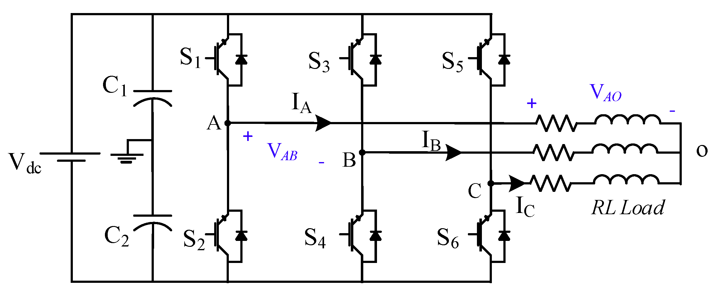
Figure 1. Schematic circuit of 3φ 3-Level inverter.
Electronics 09 01924 g001
Figure 2. Output line and phase voltage waveforms of the 3L inverter, simulated with PSIM©.
Electronics 09 01924 g002
Figure 3. Spectrum analysis of the output line voltage waveform.
Electronics 09 01924 g003
Figure 4. Classifications of the multilevel inverters (MLIs).
Electronics 09 01924 g004
Figure 5. Conventional topologies of multilevel inverters. (a) Three-level diode clamped MLIs topologies (DCMLI); (b) three-level flying capacitors MLI (FCMLI); (c) n-level cascaded H-bridge (CHBMLI).
Electronics 09 01924 g005
Figure 6. Symmetrical MLI with H-bridge. (a) [25] (b) [26] (c) [27] (d) [29] (e) [30] (f) [32] (g) [34] (h) [35].
Electronics 09 01924 g006aElectronics 09 01924 g006b
Figure 7. Symmetrical MLI without H-bridge. (a) [36] (b) [38] (c) [39,40] (d) [42] (e) [43].
Electronics 09 01924 g007
Figure 8. Asymmetrical MLI with H-bridge. (a) [46] (b) [47,48] (c) [49,50] (d) [51] (e) [53,54] (f) [55] (g) [56].
Electronics 09 01924 g008aElectronics 09 01924 g008b
Figure 9. Asymmetrical MLI without H-bridge. (a) [57] (b) [58] (c) [59,60] (d) [61] (e) [62] (f) [63] (g) [64] (h) [65].
Electronics 09 01924 g009aElectronics 09 01924 g009b
Figure 10. Different structures of hybrid MLI topologies. (a) [66] (b) [67] (c) [68] (d) [70] (e) [31] (f) [71] (g) [72] (h) [73] (i) [74].
Electronics 09 01924 g010aElectronics 09 01924 g010b
Figure 11. General configuration of the MMC circuit.
Electronics 09 01924 g011
Figure 12. Different configuration for the submodules in the MMC implementation. (a) [75] (b) [76] (c) [78] (d) [79].
Electronics 09 01924 g012
Table 1. The advantages and disadvantages of the conventional MLI topologies.
TopologyAdvantagesDisadvantages
(DCMLIs) [7,8,9,10,11]1—Depend on only single DC supply.
2—Simple structure and easy to be implemented.
3—Reduce number of components compared to the conventional inverters for the same number of steps.
4—System expansion is allowable.
5—For fundamental frequency switching operation the efficiency is high.
1—Diodes with different voltage ratings for clamping diodes are required.
2—Real power flow is difficult because of the capacitors imbalance and it tends to overcharge or discharge.
3—Need high voltage rating diodes to block the reverse voltages.
4—Extra switches, capacitors, and diodes are required for increasing the output voltage levels.
(FCMLIs) [12,13,14]1—Simple structure.
2—Reduced number of components compared to the conventional inverters for the same number of components.
3—Has a wide range of industrial applications especially in the medium and high power applications.
4—Single power supply is needed.
5—System supports modularity.
6—Deep voltage sags and short duration outages problems can be overcome through the large number of capacitors in the inverter.
1—Large numbers of capacitors are bulky and more expensive than the clamping diodes.
2—Complex control is required to maintain the capacitor’s voltage balance.
3—Switching utilization and Efficiency are poor for real power transmission.
(CHBMLIs) [15,16,17,18,19,20]1—Compared to the DCMLIs and FCMLIs it synthesizes a reduced number of switching devices.
2—It is applicable for symmetrical and asymmetrical operation.
3—No need for the power diodes or the bulky capacitors.
4—System can be extended to a high level of output power by connecting multiple units of the basic unit in series connection.
5—Has a wide range of renewable energy generation applications especially in the PV power applications.
1—Large numbers of DC suppliers in the case of system extending.
2—Extra switches and DC suppliers are required for increasing the output voltage levels.
Table 2. The advantages and disadvantages of the presented MLI topologies.
CategoryRef.AdvantagesDisadvantages
Symmetrical MLI topologies[25,26,30]- Highly modular and simple
- Applicable for renewable energy applications
- It requires non-isolated input DC sources
- Requires high number of DC suppliers
- Uses unidirectional and bidirectional switches
- Asymmetrical sources cannot be used
[27,28,29,31]- Only unidirectional switches required
- Simple structure and easy to be extended
-Many components are required for system extending
- In [29] the symmetrical sources are mandatory
[36]- Simple structure and easy to be implemented
- Modularity is available
-It uses bidirectional switches, which increase the size and the cost of the system
[38,39,40,42]- It replaces the bidirectional switches in [36] into a unidirectional set of switches- Switches with different rates are required
- Complex control
[43]- Easy and simple structure
- System support modularity
- Uses only bidirectional switches.
- Asymmetry is not possible
- Switches with different ratings are required.
Asymmetrical MLI topologies[46]- Simple structure and easy implementation
- Non-isolated DC sources are required
- Operates at high and fundamental switching frequencies
- Load sharing is not equal
- Uses unidirectional as well as bidirectional switches, which increases the losses and size.
[47,49,50]- Available for symmetrical and asymmetrical applications
- Supports modularity process
- The basic cell in [47] cannot be operated in the symmetrical configuration so it can be cascaded
[51,52]- Reduced number of components
- Use in the hybrid renewable energy sources applications
- Symmetric source configuration is not possible.
[53,54,55]- Simple and symmetric structure
- Reduced number of components are required
- Supports the symmetrical and asymmetrical configuration
- All the switches are unidirectional switches
- Modularity is not available in these configurations, so it can be extended through the cascaded connection process
[56]- Single DC source is required with the aid of a multi-terminal high switching frequency transformer
- System expansion process is available
- Complex to control
- High level of leakages in case of the high switching frequency operation
- High current spikes.
[58,63]- Simple structure
- Reduced number of switches for high number of steps
- Uses mix of unidirectional and bidirectional power switches
[64,65]- Reduced the number of DC suppliers and compensated with the chargeable DC capacitors
- Self-balancing process
- Uses both the unidirectional and bidirectional during the system implementation
- The system expansion process is not easy and needs more additional components
Hybrid MLI topologies[66]- High number of steps in the output waveform
- Reduced number of components.
- It uses a mix of unidirectional and bidirectional power switches
- Diodes with a different rating are required
[67,68,69] - Reduces the losses and costs
- Control strategy ensures a self-balancing for the capacitor
- The system implementation based only on the unidirectional power switches
- Complex control
- In case of system expansion the complexity of the system increases
[72,73]- Simple structure
- Reduced number of DC suppliers and substituted with the virtual DC sources
- No need for the isolated DC power sources
- The charging and balancing process of the capacitors is complex
- Uses unidirectional as well as bidirectional power switches
- High circulating current.
- Asymmetric source configuration is not possible
Table 3. Comparison between the different configurations for the submodules (SMs) in the modular multilevel converter (MMC).
SM ConfigurationNumber of ComponentsNumber of Output LevelsSize of Losses
half-bridge2switches+ capacitor2It handles low power losses because it uses less switches compared to the other SM configurations.
full bridge4switches+ capacitor2Due to the relatively large number of switches compared to MMC based half bridge, the power losses, as well as the cost, increased.
The clamp-double5switches+ 2capacitors + 2diodes5This configuration records a higher percentage of power losses compared to the MMC based half-bridge and a lower percentage compared to the MMC based full bridge.
The three-level converter: NPC4switches+ 2capacitors + 2diodes3The MMC based FCSM has the same power losses compared to MMC based half bridge SM; however, the MMC based NPCSM has high power losses compared to the MMC based half bridge SM. However, the complexity of the circuit, as well as the capacitor voltage balancing difficulties, limit the use of this configuration.
The three-level converter: FC4switches+ 2capacitors3
The five-level cross-connected6switches+ 2capacitors5This configuration has the same amount of power losses compared to the MMC based clamped-double SM.
Table 4. Configuration parameters and the calculated performance parameters.
Ref.LevReferences Specifications Performance Parameters
NSupNCapNTranNSwNDNPolesNAuxNCom/LevNavg/poleTSV p.uTHD
DCMLI312042204.52.5269.8%
FCMLI3130402042263.75%
CHBMLI310040202.52248%
[25]9400103503.42.81617.9%
[26]11500124603.52.832311.4%
[27,28]7300100403.254.251622.6%
[29]9400110502.85.220 -
[30]730080402.752.5109.27%
[31]11300100602.162.33179.07%
[34]7300724033.2512 -
[35]713084404321 -
[36,37]13300160702.752.29246.33%
[38]71106040231222.45%
[39,40]530080303.665.331831.5%
[42]730080402.75412 -
[43]9400100502.84.21812.66%
[47,48]13400160702.86424 -
[49,50]15300120801.8756.2522 -
[51,52]920090502.23.6189.19%
[55]520060302.673817.56%
[56]491042802501.3241288.77%
[57]72006040231216.4%
[58]17400120901.784.11402.77%
[61]1130080601.833.3321 -
[62]15300100801.6254.37534 -
[64]13220140702.575.14323.87%
[65]13240122702.865.5765.31%
[66]192401261002.46.238 -
[67]212301441102.14.54606.25%
[70]9400100502.83.226 -
[73]9220745033.81513.8%
[74]213001001101.182.55403.9%
Publisher’s Note: MDPI stays neutral with regard to jurisdictional claims in published maps and institutional affiliations.