Abstract
The system for stabilizing an operating point of remote integrated optical Mach–Zehnder modulators with a dual output has been developed. The designed electronic circuit for precise bias control had low power consumption (less than 5 mW) and could be powered through optical fiber by signal optical radiation at a wavelength of 1550 nm with a power of 15 mW. The experimental demonstration of common mode noise rejection proved a high accuracy of the quadrature operating point setting and stabilization, resistance to the light intensity noise, and low level noise and distortion added to the transmitted signals.
1. Introduction
Many examples of using fiber-optic communication lines for transmitting millimeter and micrometer waves signals over long distances are currently known. In particular, ref. [1,2,3] describe the potential applications of fiber-optic communication lines for transmitting high-frequency signals in distributed transceiver systems with remote antennas, including for transmitting broadband signals in wireless networks, radio astronomy systems, radars, etc.
These systems typically have the architecture of the external amplitude modulation with direct detection. It is well-known [4,5] that an electro-optical modulator can be used in such systems, and its operating point is maintained with a special electronic system with feedback requiring additional electrical power. This is not very convenient in the case of modulators on remote antenna posts [6], which generally have a limited energy budget. It is sometimes impossible to use an industrial electrical network to power the system for maintaining the operating point due to the remoteness and inaccessibility of spaced antenna systems. Therefore, the problem of supplying the operating point stabilization system via optical fiber is urgent.
The first proposals to use fiber-optic communication lines for transmitting energy rather than just the information signal were formulated in the late 1970s [7] in the context of activating remote audible signaling by optical means only. Following the publication of that study, various systems taking advantage of optical power have been developed. Different applications of this technology were described for remote sensing systems, for powering computer networks, and even in medicine [8,9,10].
The advantages of using optical fiber for the transmission of power include [11,12,13]:
- (a)
- long cable sections without signal regeneration devices;
- (b)
- intrinsic safety, no current leakage;
- (c)
- electromagnetic compatibility is ensured due to:
- lack of galvanic connection between the receiver and the transmitter;
- absence of metal conductors, which are parasitic transmitting and receiving antennas for radiation in the radio frequency range.
- (d)
- corrosion resistance;
- (e)
- longer fiber-optic cables have a smaller cross-section, weight, and also lower cost compared with equivalent cables with copper or aluminum conductors.
The properties listed above, as well as the results given in [14], suggest that optical fiber can be considered as a sufficiently reliable medium for power transmission [15]. Nevertheless, it should be kept in mind that increasing the number of transmitted channels over one fiber, using optical amplifiers with a high output power in order to increase the distance and transmission coefficient of microwave signals, leads to the fact that the optical power in the fiber can reach 1 W or more [16]. Introducing an additional channel for transmitting energy can result in malfunction of the line in these conditions.
In this paper, we consider the possibility of using signal optical radiation to implement the electrical power supply for a stabilization system of the operating point of a remote integrated optical Mach–Zehnder modulator based on lithium niobate. The goal was a minimization of the optical power delivered for stabilization system powering. The choice of the optical range near 1550 nm for power transmission is determined by the requirement to minimize losses in the optical fiber when transmitting power over long distances (more than 1 km). A scheme for bias control and stabilization with low power consumption was developed and stable operation of the modulator at an optical power level of less than 20 mW at its input was demonstrated.
2. Power Over Fiber System for a Remote Electro-Optical Modulator
2.1. System Architecture
The integrated optical modulator based on lithium niobate is a polarization-dependent device. The modulation efficiency is significantly higher for linearly polarized light directed along the optical axis of the crystalline substrate [2,3]. Light with orthogonal polarization is modulated with lower efficiency and, moreover, can cause additional interference noise in the transmitted signal. For this reason, modulators usually work with polarized light at the input [2,17]. This allows orthogonal linear polarization light to be used for power transmission.
The following architecture was proposed for the system simultaneously transmitting signal optical radiation and delivering power to the scheme for modulator bias control and stabilization (Figure 1).
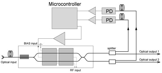
Figure 1.
Schematic of stabilization system for operating point for the Mach–Zehnder modulator on lithium niobate substrate with two optical outputs.
The so-called depolarized source was used as a source of optical radiation [18], consisting of two standard distributed feedback laser diodes. The radiation from the diodes was combined into one standard single-mode fiber in the form of two orthogonal polarization components of equal amplitude using a fiber polarization combiner. In order to eliminate interference noise, the wavelengths of laser diodes were chosen so that the frequencies of the interference beats are located outside the band of transmitted information signals. In the case of propagation along a fiber without preserving polarization, the polarization components changed, but the total optical power in any linear polarization component remained constant. A fiber polarization splitter was placed at the input of the external remote modulator and divided the incoming optical radiation into an information component, which is used as an optical carrier for modulation, and an energy component, which is converted using a photovoltaic converter. A multi-element semiconductor converter was used. The electric power from the output of the photovoltaic converter was used to feed the scheme of the modulator bias control and stabilization.
The photovoltaic converters currently developed in the range of telecommunication wavelengths of 1300–1600 nm typically have a relatively low conversion efficiency of ≈20% and a limitation on the maximum optical power of ≈100 mW. For this reason, the low power consumption of an electronic system for stabilizing the operating point powered by optical fiber at the signal wavelength is a particularly crucial issue.
2.2. Low-Power-Consumption Stabilization System of an Operating Point
The problem of setting and maintaining the operating point has to be solved for integrated optical modulators in fiber-optic communication lines [19]. Low frequency bias electrodes are used for operation point control. The current position of the operating point of the modulator largely determines the transmission coefficient as well as the coefficient of nonlinear distortion [20]. A quadrature operating point is commonly used for integrated optical Mach–Zehnder modulators, where the maximum slope (modulation efficiency) as well as the greatest linearity of its transfer characteristic are achieved. The accuracy of the operating point setting significantly affects the level of nonlinear distortion. There are two approaches to setting the operating point of the modulator. The first is based on controlling the constant component of the optical power at the output of the modulator and has a very simple circuit design but provides a relatively low accuracy of setting and maintaining a given operating point. The second approach is based on using a pilot harmonic signal, detecting and controlling the higher harmonics generated by the nonlinear transfer characteristic of the modulator. This approach is highly accurate because coherent methods are introduced for processing the pilot signal; however, it requires complicated electronic circuits, which leads to higher power consumption. In addition, the pilot signal introduces additional noise into the signal path, which can negate the benefits of an accurate operating point setting.
The proposed system uses a special modification of an integrated optical modulator with a dual output, which was manufactured at the Quantum Electronics Laboratory of the Ioffe Institute [21,22]. This type of modulator allows balanced detection of the constant component of the optical power, ensuring that the operating point is set with an accuracy close to that of a system with a pilot signal but with significantly lower power consumption and without additional noise in the signal path. The high balancing accuracy of the two arms of the modulator was provided by the original technology for adjusting the splitting ratio of the output waveguide directional coupler [23].
The equal levels of optical power at the output ports of the modulator correspond to the quadrature operating point. A microcontroller-based circuit for stabilizing the operating point was designed to implement feedback. A programmable microcontroller was used as a calculation and control unit, making it possible to combine the bias control and operating point stabilization circuit and the modulator itself into a single transmitting unit with automatic compensation of the drift of the modulator transfer characteristic.
Fiber optic power splitters were used for the optical power monitoring at the output ports of the modulator, diverting part of the output radiation to photodiodes (PDs), the electrical signal from which was amplified and fed to the input of an external multichannel analog-to-digital converter (ADC). Amplification of the output signal of the photodiodes makes it possible to use the dynamic range of the ADC more effectively, and it also allows reducing the optical power removed from the output ports of the modulator to control the current operating point to 1%, thus minimizing the negative effect of the stabilization system on the overall transmission coefficient of the line. Next, the voltage across the photodiodes in the form of ADC readings is transmitted to the microcontroller (MC) and used to calculate the bias voltage required to compensate for the drift of the modulator transfer characteristic. At the end of the calculations, the required voltage value is set at the output of the external digital-to-analog converter (DAC), amplified, and fed to the bias electrodes of the modulator. Amplification of the DAC output signal allows expanding the range of control voltages, which makes it possible to control the operating point over a wide range and also increases the efficiency of the tuning system, regardless of the value of the half-wave voltage of the modulator.
Taking into account the typical drift behavior of modulators on lithium niobate substrates and the need to minimize power consumption for the stabilization system to operate, components with the following parameters were selected:
An ADuCM 361 microcontroller from Analog Devices with an extended number of processor instructions and built-in DAC and ADC provided high performance in mathematical calculations, which was especially important for floating point arithmetic. Perhaps most importantly, this chip provided low power consumption: less than 1 mW in active mode.
Photodiodes with a rather large internal capacitance about 2 pF, which determined their bandwidth (<1 GHz), were used for the stabilization system. The bandwidth of the feedback was advisedly reduced to 10 MHz to maintain the system’s stability when a high-frequency baseband signal is applied to the RF input of the optical modulator.
2.3. Algorithm for Stabilizing the Operating Point
The algorithm of the operating point stabilization system can be briefly presented as follows:
- Calculation of the signal error function by analyzing the difference between the input and the reference signal.
- Formation of the control signal as the sum of three components (proportional, integral, and differential components).
- Subtracting the control signal from the input signal.
- Re-analysis of the error and repetition of the cycle from 1–3.
The algorithm implemented in the stabilization system is based on a PID (Proportional–integral–derivative) controller. The general diagram of the PID controller is shown in Figure 2. The principle of operation of the PID controller is based on calculating the error function as the difference between the current input signal and the reference.
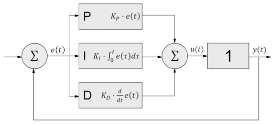
Figure 2.
General diagram of PID (Proportional–integral–derivative) controller.
The system for stabilizing the operating point uses the ratio of the voltages at the outputs of the photodiodes as an input signal. The error function describing the deviation of the operating point of the modulator from the given position was found as the ratio of the instantaneous output powers of the modulator outputs and :
where Γ is the reference value of the input signal of PID controller; and is the coefficient of balancing the asymmetry in the channels for controlling the output power of the modulator. The error function was determined in terms of the difference, yielding a negative feedback between the input and output signals of the controller. The resulting error function is used to generate a control signal, which is the sum of the proportional, integral, and differential components multiplied by the corresponding factor.
where are the proportional, integral, and differential coefficients, respectively; is the error function.
The proportional term of the PID controller introduces a linear dependence of the control signal on the input signal. If the proportional component only is used, the system tends to the reference value, but a stable setting at the given operating point cannot be achieved. The limitation arises from a statistical error associated, in this case, with the discreteness of the ADC output signals, as well as with the noise of the input laser radiation.
The integral component of the controller is proportional to the integral of the error function over time. Adding an integral term allows the controller to overcome the statistical error. In the absence of external disturbances in the system, the position of the current operating point is stabilized at the quadrature point. In this case, the error function is equal to zero, similar to the proportional term, and the control signal depends only on the integral term.
The derivative is proportional to the time derivative of the error function and describes the change rate of the error function. Adding a differential component improves the stability of the system if there is an abrupt shift in the transfer characteristic. It also reduces the time it takes to reach the quadrature point from the starting position.
The contributions from the components are determined by the values of the corresponding coefficients, which are set taking into account the characteristics of a particular system. The values of the PID controller coefficients were searched consequently and ensured the stability of the system as well as a minimum settling time of 20 s from the initial position to the quadrature point. Recursive methods were used for calculating the control voltage of the controller to increase the speed of the stabilization system.
The key to accurately setting and stabilizing the operating point in quadrature is measuring the powers of the modulator output signals uniformly. However, asymmetry inevitably arises in the measuring paths in the process of manufacturing the stabilization system. The result of this asymmetry is the difference in ADC readings when passing the quadrature point, with the system consequently stabilizing at a random operating point. Calibration methods were developed aimed at compensating for the asymmetry arising in the optical and electrical parts of the measuring path.
Operational amplifiers at the outputs of the photodetectors are the main source of asymmetry in the electrical path. A real operational amplifier, unlike an ideal one, has a non-zero bias voltage between the inputs. This results in a constant addition to the photodiode voltage, which is different in each channel. Calibration was performed to determine the offsets of the amplifiers, which consisted of determining the averaged voltages at the outputs of each of the amplifiers in the absence of input laser radiation. The obtained values are subtracted from the ADC readings during system operation, thus discarding the constant addition to the voltages at the outputs of the amplifiers.
The asymmetry in the optical path is determined by the difference in optical losses in each channel, arising as the radiation is diverted from the outputs of the modulator to the photodiodes due to differences in the splitting ratio of the fiber optic couplers, and it may also occur during the manufacture of the modulator itself in the form of asymmetry of the output arms. An additional calibration algorithm was developed to compensate for the optical asymmetry in the measuring path. As the voltage is changed at the DAC output during calibration, the modulator is set to the position corresponding to the maximum optical power in the first output; then, the algorithm is repeated for the second output of the modulator. The ratio of the obtained ADC readings determines the asymmetry in the measuring path of the stabilization system. Dividing by the obtained coefficient to determine the current position of the operating point in calculations of the error function accounts for the difference in optical losses corresponding to measuring the power at the outputs of the modulator and provides equal values of ADC readings at the quadrature point of the modulator.
Importantly, the electrical part must be calibrated before the optical part in order to avoid the influence from the bias of photodiode amplifiers on the accuracy with which the asymmetry of the optical path is determined. To ensure the same accuracy of the stabilization system for varying ADC gains, the electrical and optical parts of the measuring path were calibrated for all values of the ADC gain. The obtained calibration values were stored in the non-volatile memory of the microcontroller using an accidental erasure protection algorithm.
3. Experimental Demonstration
Figure 3 demonstrates the successful start of the stabilization system from an optical power of 15 mW at the input of the photovoltaic converter. The blue curves represent the voltage at the output of the DC–DC converter supplying the operational amplifier. The converter did not start at 10 mW optical input power and provided stable output voltage: about 8 volts at 15 mW. The corresponding electrical power consumption could be estimated from the known photovoltaic converter efficiency of 30% and was smaller than 5 mW. The gray curves correspond to the voltages at the output of the photovoltaic converter when the input optical power is applied. The red curves in Figure 3 shows the response of the output voltage of the stabilization system when it is turned on. The zero control signal was at 10 mW optical power. The exit to the working point and its stabilization was observed at 15 mW optical power.
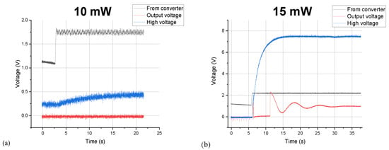
Figure 3.
Experimental demonstration of power supply of the system for stabilizing the operating point from radiation at a wavelength of 1550 nm: (a) system fails to start at an input optical power of 10 mW, (b) normal operation of the system at an input optical power of 15 mW.
The time to reach the stabilized operating mode was 20 s. The high amplitude of oscillations in the first seconds of stabilization is associated with the excitation of a fast drift in the modulator when the bias voltage is switched at the moment when the system is turned on. The controller time constant τPID = 12 ms. The optical losses introduced into the line by the stabilization system were determined only by the drop in intensity at the fiber optic couplers, which amounted to ≈0.01 dB at 1% of the rejected power.
Demonstration experiments on suppressing the common-mode noise were carried out to assess the performance of the stabilization system. Common-mode noise suppression was implemented on a fiber-optic link with a remote Mach–Zehnder modulator with a dual output and a balanced photodetector. The effectiveness of common mode noise suppression depends on the accuracy of setting and stabilizing the operating point of the modulator in quadrature. The source of common-mode noise is either the relative intensity noise (RIN) of the laser diode at the input of the modulator or another source of parasitic amplitude modulation of the input light.
The experimental setup in Figure 4 uses an additional integrated optical Mach–Zehnder modulator as a noise source, with the signal from a white noise source fed to its RF input. The system stabilized the operating point of the dual output modulator in quadrature. The output electrical signal of the demodulation unit was fed to a tunable narrow-band lock-in amplifier, which determined the level of the input noise attenuation. The results of the study of common-mode suppression in the frequency range up to 3 GHz are shown in Figure 5.

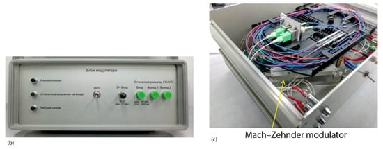
Figure 4.
Scheme for demonstration of the common-mode noise suppression. (a) general scheme of the device, (b) photo of the device case, (c) Mach-Zehnder modulator in the system.
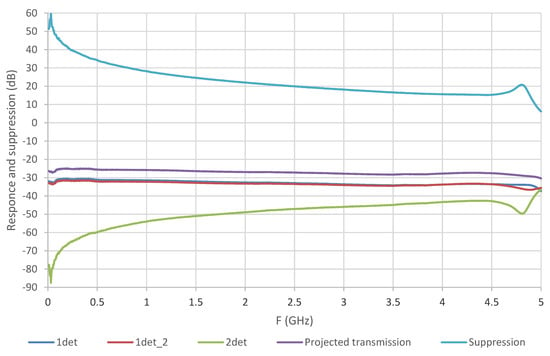
Figure 5.
Common mode noise suppression by balanced detection. “1det”—system transmission coefficient curve with a single detector connected (first one); “1det_2”—system transmission coefficient curve with a single detector connected (the second one); “2det” curve−difference between two channels; “Projected transmission”—system transmission coefficient curve with balance detection; “Suppression”—system common-mode rejection with balance detection.
It has been demonstrated that it is possible to effectively reject common-mode interference by more than 14 dB in the frequency bandwidth up to 3 GHz. To further improve noise suppression, it is required to align the optical cable lengths with greater precision. It has also been established that the stabilization system of the operating point powered by optical radiation at the signal wavelength can be used, accurately setting and maintaining the quadrature value at a high level of intensity noise in the optical radiation at the modulator input.
4. Conclusions
We have developed and produced a system for controlling the operating point of integrated optical Mach–Zehnder modulators with a dual output, which has a high accuracy and low power consumption (less than 5 mW). The incident optical power was 15 mW, and the efficiency of photovoltaic converters is about 30%. We have experimentally confirmed the possibility of powering the stabilization system for an operating point via a single-mode optical fiber with signal optical radiation at a wavelength of 1550 nm with a power of 15 mW. Using the developed system for stabilization of the operating point in experiments to suppress noise and common-mode interference, we have proved its high accuracy, resistance to noise in the input, and low-level additional noise and distortion in the output signal of the modulator.
Solutions and algorithms of the operating point stabilization system proposed in this work can be used to improve the noise characteristics in systems for estimating the parameters of signals with distributed receiving antennas using fiber-optic communication lines.
Author Contributions
Conceptualization, A.S. and V.S.; Formal analysis, A.P.; Investigation, A.P., A.T. and P.A.; Methodology, A.P. and A.S.; Project administration, A.P.; Writing—original draft, A.P.; Writing—review and editing, A.S. and V.S. All authors have read and agreed to the published version of the manuscript.
Funding
This work in Peter the Great St. Petersburg Polytechnic University was supported by State assignment for basic research (project № FSEG-2020-0024).
Conflicts of Interest
The authors declare no conflict of interest.
References
- Waterhouse, R.; Novack, D. Realizing 5G: Microwave Photonics for 5G Mobile Wireless Systems. IEEE Microw. Mag. 2015, 16, 84–92. [Google Scholar] [CrossRef]
- Chen, A.; Murphy, E.J. Broadband Optical Modulators: Science, Technology and Applications; CRC Press: Boca Raton, FL, USA, 2012; p. 568. [Google Scholar]
- Urick, V.J.; Williams, K.J.; McKinney, J.D. Fundamentals of Microwave Photonics; John Wiley & Sons: Hoboken, NJ, USA, 2015; p. 496. [Google Scholar]
- Lebedev, V.V.; Il’Ichev, I.V.; Agruzov, P.M.; Shamray, A.V. The influence of the current-carrying electrode material on the characteristics of integral optical microwave modulators. Tech. Phys. Lett. 2014, 40, 743–746. [Google Scholar] [CrossRef]
- Petrov, A. Radiophotonics Module to Increase the Distance of the Remote Antenna. In Proceedings of the 2019 IEEE International Conference on Electrical Engineering and Photonics (EExPolytech), Saint Petersburg, Russia, 17–18 October 2019; pp. 348–350. [Google Scholar]
- Petrov, A.; Velichko, E.; Lebedev, V.; Ilichev, I.; Agruzov, P.; Parfenov, M.; Varlamov, A.; Shamrai, A. Broad-Band Fiber Optic Link with a Stand-Alone Remote External Modulator for Antenna Remoting and 5G Wireless Network Applications. In Lecture Notes in Computer Science; Springer: Cham, Switzerland, 2019; pp. 727–733. [Google Scholar]
- Deloach, B.C.; Miller, R.C.; Kaufman, S. Sound Alerter Powered Over an Optical Fiber. Bell Syst. Tech. J. 1978, 57, 3309–3316. [Google Scholar] [CrossRef]
- Werthen, J.-G. Powering Next Generation Networks by Laser Light over Fiber. In Proceedings of the OFC/NFOEC 2008—2008 Conference on Optical Fiber Communication/National Fiber Optic Engineers Conference, San Diego, CA, USA, 24–28 February 2008; pp. 1–3. [Google Scholar]
- Tamura, T. Transcutaneous optical power converter for implantable devices. Proc. SPIE 1994, 2084, 99–104. [Google Scholar]
- Dumke, M.; Heiserich, G.; Franke, S.; Schulz, L.; Overmeyer, L. Power Transmission by Optical Fibers for Component Inherent Communication. Syst. Cybern. Inform. 2010, 8, 55. [Google Scholar]
- Basanskaya, A. Electricity over Glass. IEEE Spectr. 2005, 40, 18. [Google Scholar] [CrossRef]
- Cohen, M. Power-over-fiber drives remote data exchange. OPTO Laser Eur. 2006, 140, 27–29. [Google Scholar]
- Yasui, T.; Ohwaki, J.; Mino, M.; Sakai, T. A STable 2-W Supply Optical-Powering System. In Proceedings of the 28th Photovoltaic Specialists Conference, Anchorage, AK, USA, 15–22 September 2000; pp. 1614–1617. [Google Scholar]
- Hou, V. Update on Interim Results of Fiber Optic System Field Failure Analysis. Proc. NFOEC 1991, 1, 539–545. [Google Scholar]
- Zediker, M.S.; Rinzler, C.C.; Faircloth, B.O.; Moxley, J.F. Optical Fiber Cable for Transmission of High Power Laser Energy Over Great Distances. U.S. Patent 9,347,271, 24 May 2016. [Google Scholar]
- Tajima, N.; Kamiyama, D.; Matsuura, M. 150-Watt Power-over-Fiber Feed for Bidirectional Radio-over-Fiber Systems Using a Double-Clad Fiber. In Proceedings of the Optical Fiber Communication Conference (OFC), San Diego, CA, USA, 3–7 March 2019; p. W1I-7. [Google Scholar]
- Cox, C.; Lu, X.; Piprek, J.; Bowers, J.E.; Betts, G.E.; Howerton, M.M.; Burns, W.K.; Van Eck, T.; Yu, P.; Wu, M.C.; et al. RF Photonic Technology in Optical Fiber Links; Cambridge University Press: Cambridge, UK, 2002. [Google Scholar]
- Burns, W.K.; Moeller, R.P.; Bulmer, C.H.; Greenblatt, A.S. Depolarized source for fiber-optic applications. Opt. Lett. 1991, 16, 381–383. [Google Scholar] [CrossRef] [PubMed]
- Sisto, M.M.; LaRochelle, S.; Rusch, L.A. Gain Optimization by Modulator-Bias Control in Radio-Over-Fiber Links. J. Light. Technol. 2006, 24, 4974–4982. [Google Scholar] [CrossRef]
- Bulmer, C.; Burns, W. Linear interferometric modulators in Ti: LiNbO3. J. Light. Technol. 1984, 2, 512–521. [Google Scholar] [CrossRef]
- Petrov, A.; Lebedev, V.; Agruzov, P.; Ilichev, P.; Shamrai, A.; Liokumovich, L.; Kudryashova, T.; Sorotsky, V. Lithium Niobate Direction Coupler Modulator for Linearization of Analog Optical Signal Transmission. In Proceedings of the 2020 IEEE International Conference on Electrical Engineering and Photonics (EExPolytech), Saint Petersburg, Russia, 15–16 October 2020; pp. 80–84. [Google Scholar]
- Petrov, A.; Parfenov, M.; Lebedev, V.; Ilichev, I.; Agruzov, P.; Tronev, A.; Shamrai, A. Dynamic Range Improvement of Broad-band Analog Fiber Optic Links with Special Lithium Niobate Integrated Optical Modulators. In Internet of Things, Smart Spaces, and Next Generation Networks and Systems; Springer: Cham, Switzerland, 2020. [Google Scholar]
- Chen, F.S. Optically Induced Change of Refractive Indices in LiNbO3 and LiTaO3. J. Appl. Phys. 1969, 40, 3389–3396. [Google Scholar] [CrossRef]
Publisher’s Note: MDPI stays neutral with regard to jurisdictional claims in published maps and institutional affiliations. |
© 2020 by the authors. Licensee MDPI, Basel, Switzerland. This article is an open access article distributed under the terms and conditions of the Creative Commons Attribution (CC BY) license (http://creativecommons.org/licenses/by/4.0/).