1. Introduction
Progress in the field of microelectronics, telecommunications and software engineering allows one to reach a new level of complexity of the created anthropogenic systems, characterized by an increase in the number of subsystems, structural complexity of connections between subsystems and behavior complexity. In addition, the level of structural dynamics and the use of dynamic business processes is constantly increasing. A considerable number of systems have a hierarchical structure. The functioning of the systems can be characterized by intelligent behavior. In these conditions one can observe the transition to intelligent systems.
The term “Intelligent system” itself cannot be clearly defined. There are two alternative approaches to assessing the system intelligence level. The first approach involves the possibility of solving a certain set of problems that cannot be solved within traditional approaches, which requires the availability of generally recognized benchmarks. The second approach is based on the application of a certain set of technologies that can be defined as mechanisms for intelligent data processing. Such mechanisms may include knowledge management as described in Russell et al.; Jackson [
1,
2].
New paradigms for Software Intensive Systems (SIS) construction are constantly appearing and acquiring practical applications. Modern paradigms, that fully meet the observed trends, include such paradigms as the Internet of Things (IoT)—Streitz et al., Marques et al. [
3,
4], Industrial Internet of Things (IIoT)—Boyes et al. [
5], Cyber-Physical Systems, (CPS)—Sanfelice [
6], socio-cybernetic systems, Ambient Intelligence Systems, (AmIS)—Streitz et al., Korzun et al. [
3,
7], which in some cases overlap, but more often complement each other. SIS created in accordance with these concepts can be classified as large and/or complex intelligent systems—Bertalanffy [
8]. The tendency to support cognitive functions in such systems is gaining strength. Most of these paradigms are implemented in the form of technologies. (In this case, technology refers to a set of models, methods, algorithms, frameworks, as well as a developed market of hardware and software components necessary to create SIS of a certain class that implement this paradigm.) New generation SIS are developed to solve a wide variety of tasks. They include the tasks of data collection, management and others.
These tasks’ solving requires the implementation of data collection (DC) procedures both on the observed systems (ObS), and on the DC System (DCS) in order to maintain it in an operable state, as well as to optimize its functioning.
Currently, there are different statements of DC problem in SIS. DC task in SIS can be defined as the process of obtaining data from different sources and providing them to the stakeholders according to their roles in the required form. When one develops SIS, which can be classified as a large and/or complex system with a dynamic structure and cognitive behavior, the DC stops being a trivial procedure. The challenge is to realize effective DC procedures for large scale AmIS with dynamic structure and dynamic behavior.
This article considers the problems of creating DCS, which can be classified as AmIS, based on fog platforms [
9]. For developing AmIS oriented DCS it is proposed to use knowledge-based models. The distinctive feature of the proposed technology is that ObS models are generated and maintained automatically to be up-to-date. The article offers an approach to building DCS that allows one to solve a number of key problems related to DC in AmIS.
This article consists of 12 sections.
Section 1 describes the peculiarity of AmIS as an ObS.
Section 2 analyzes the existing approaches to DCS construction and gives a conclusion on the limited possibility of their use for DCS construction, focused on DC in AmIS, which can be classified as large and complex intelligent systems with cognitive capabilities.
Section 3 describes the conditions for collecting data in AmIS.
Section 4 defines the requirements for DCS in AmIS and sets the research objective.
Section 5 describes the conceptual model of DC, which forms the basis of the proposed technology.
Section 6 considers the private models used at the DCS creation.
Section 7 covers DC technologies at the physical and network levels.
Section 8 describes possible approaches to DCS implementation.
Section 9 assesses the proposed technology readiness degree for practical use.
Section 10 discusses possible approaches to constructing cognitive DCS.
Section 11 gives an example of the proposed technology practical use. Conclusion assesses the obtained results and determines the further direction of work.
2. AmIS: Preliminaries
AmIS is usually defined as follows. AmIS refers to electronic environments that are sensitive and responsive to the presence of humans. The ambient intelligence idea is to support humans at performing their everyday life activities, in an intuitive way using information and intelligence hidden in the network connecting these devices. As these devices grew smaller, better connected and more integrated into the environment, the technological framework behind them disappeared and humans interacted only with the user interfaces. This idea is about hospitals, public transportation, production facilities, and other environments. Ambient intelligence is based on several concepts and technologies like context awareness, pervasive computing, ubiquitous computing, profiling, agile computing, cognitive computing, and human-centric computer—Gams et al. [
10].
According to the AmIS concept it should possess the following distinctive features:
embedded: many networked devices are integrated into the environment;
context aware: these devices can recognize situational context;
personalized: AmIS can be tailored to human needs;
adaptive: AmIS can change their behavior and interfaces in response to the human needs and the situational context;
anticipatory: they can anticipate humans desires without conscious mediation.
While studying the list of properties that AmIS is expected to have, it becomes obvious that they should represent integrated, context-aware, adaptive systems. These properties assume that systems implement the elements of intelligent behavior. It is possible to add the learning ability of systems.
It should be noted that the concept of ambient intelligence implies the availability of a large number of services of different levels that allow the implementation of complex activities. The implementation of the paradigm requires a certain number of systems, usually CPS. From this point of view, AmIS can be defined as a system of interconnected CPS that use knowledge management mechanisms, which are presented to users as a single system that implements elements of intelligent behavior, with which they can communicate using a certain domain-specific language (DSL)—Fowler [
11]. AmIS concept is receiving more and more practical applications, its best-known implementations are the systems like smart home, smart city, production and military systems, etc. For the most part, these are multi-level distributed systems built on fog platforms which use a service-oriented architecture (SOA).
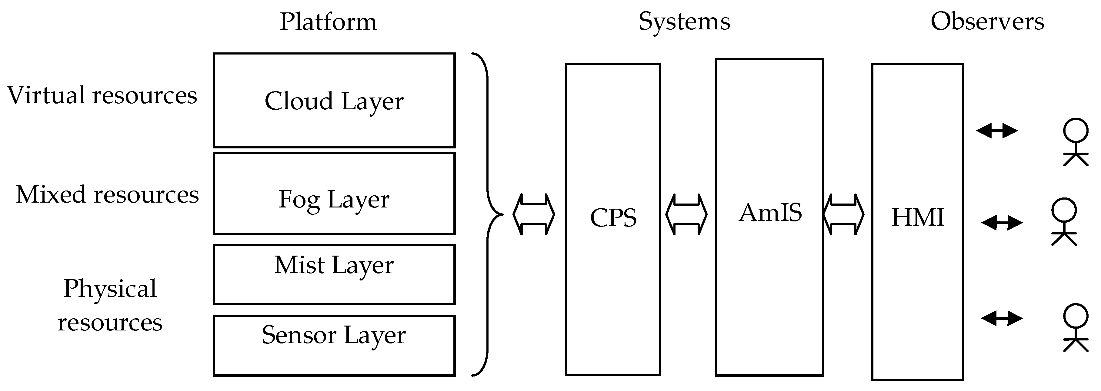
The structure of modern AmIS, based on the fog computing platform, is given in
Figure 1. It comprises three main elements: a distributed platform, distributed CPS, and observers. The fog platform usually includes four levels: Cloud Layer, Fog Layer, Mist Layer and Sensor Layer. At the lower levels (Sensor Layer and Mist Layer), physical resources are usually used. At the top level (Cloud Layer), on the contrary, virtual resources, public and private clouds in particular, are used. However, hybrid solutions are preferable. At the middle level (Fog Layer), both physical and virtual resources can be chosen.
The platform provides a variety of services that can be used for creating of a number of CPS. Commonly the AmIS consists of many CPS, which can be integrated at different levels. Multiple AmIS can be created on a single platform. In a certain sense, AmIS can be considered as the CPS further development, i.e., as a system of CPS.
Users (observers) have different concerns, different rights, and different locations. Different users can communicate with AmIS using different DSLs.
It should be noted that a significant part of AmIS are systems of low cost category and Total Cost of Ownership (TCO) is their important characteristic. One of the effective ways of reducing TCO is the use of self-management mechanisms. The minimizing of TCO can be conceded as one of the challenges for ImIS developers.
3. Approaches, Available for DCS Construction in Distributed Systems
The DC task is a well known one. The experience gained in building embedded systems for various purposes, such as real-time systems—Akenine-Möller et al. [
12], wireless sensor networks—Iyengar et al. [
13], distributed computing systems—Hwang et al. [
14], corporate information systems [
15], and IoT systems—Boyes et al. [
5], can be useful for DCS construction.
The experience in building real time systems is important because an essential part of modern AmIS works in real time and can be conceded as real time systems. Wireless sensor networks give us a lot of preprocessing and data fusion algorithms. Modern AmIS for the most part are distributed systems, and a lot of technologies can be borrowed from the domain of classical distributed systems, i.e., virtualization. Corporate information systems are interesting, first of all from the point of view of multilevel network structures management technologies. An essential part of modern AmIS is built on the IoT platforms and this fact is to be taken into account.
However, it should be noted that modern AmIS are much more complex than the listed systems, primarily due to the presence of high structural dynamics and high behavior dynamics.
Real time systems are overwhelmingly the control systems. If the control object has a static structure and the amount of data is small, then there are no special problems. However, if the managed system belongs to the class of large and/or complex ones, then the problem of organizing the DC process becomes too complex. Distributed systems represent a broad subclass of SIS. The greatest problems of DC occur in systems with a dynamic structure and cognitive behavior, especially in case of severe constraints on characteristics like the bandwidth of communication channels, response time, power consumption, etc.
DC technologies used in corporate information systems are well developed [
15]. For the most part these are powerful and expensive systems that implement DC procedures in large-scale systems based on Simple Network Management Protocol (SNMP). The solutions used within these systems are of particular but limited interest and cannot be used directly due to their complexity. Besides, these solutions focus mainly on static structures and assume a permanent human participation.
DCS technologies used in classic sensor networks are also well known. Most of them are systems for data fusion received from similar or different types of sensors—Blasch et al.; Fotiou et al. [
16,
17]. In most cases the structure of sensor systems is assumed to be static.
A significant number of different models and technologies for DC have been developed within the IoT concept. In Fotiou et al. [
17], a DC model based on the use of the middleware platform was proposed. The platform developed in Fotiou et al. [
17] allows the management of the collection and processing of heterogeneous data coming from various types of IoT devices, including devices with limited resources. The platform ensures compliance with the requirements for the quality of the data provided, in particular, their accuracy, as well as data security requirements. Moreover, the platform provides an opportunity to develop compromise solutions in case of constraints on the consumed power. However, the platform does not address the problem of data transfer latency.
In Cui et al. [
18], a decentralized data management platform is proposed for data transfer from IoT devices to a cloud service. In Oma et al. [
19], a linear model is proposed based on the search for data transfer paths between end devices and fog nodes, that takes into account data processing capabilities. Model application helps to find the shortest data transmission ways and, accordingly, reduce the consumed power and the time spent on data transmission. However, other IoT requirements, such as reliability and security requirements, are not fulfilled.
In Tang et al. [
20], a real time DC model is suggested, this model is focused on reducing the consumed power. The usage of this model allows the reduction in the number of packets transmitted over the network when collecting data from multiple devices. In addition, the model permits one to avoid many errors that occur during data transmission. It allows the compression of data prior to transmitting. However, only possible power consumption problems are solved by the proposed model, and other IoT problems, including data transmission delays and data transmission reliability, are excluded from consideration.
A model based on resource sharing has also been developed to reduce power consumption—Kouvelas et al. [
21]. In [
21] graphs and metrics of graphs, the use of which can significantly reduce the power consumed in IoT networks and significantly increase their lifespan are considered. However, this model is also mainly focused on resolving the problem of the power consumption. Another way to increase the network lifetime is proposed in Li et al. [
22]. The model proposed in Li et al. [
22] also provides a high data transfer rate under conditions when data are transmitted between two nodes—the transmitter node and the receiver node. Under these conditions, the model provides low power consumption and high data transfer rates. However, if you need to transfer data to multiple nodes, the efficiency of the model reduces significantly.
In Jia et al. [
23], a model for solving data routing problems is proposed. The model balances network traffic at collecting data from devices. The proposed routing algorithm provides an opportunity to search for optimal data transfer paths, taking into account their length and buffer volume of each of the intermediate nodes. The advantages of the model include the ability to reduce network load and improve network reliability. Among the disadvantages of the model are the low level of data security and low data accuracy.
Alkhamisi et al. [
24] suggest a model for DC based on device clusters formation, the selection of central elements as well as the use of these elements in data transmission. Route planning is performed before data transmission. The proposed model reduces the load on the network and consumed power. However, there can be delays in data transmission during its application.
Rahman et al. [
25] show the results of a comparative study for DC models based on the LEACH-C and LEACH clustering algorithms. In [
25], the following model parameters were studied: network bandwidth, power consumption, delay in DC and transmission, and accuracy of data provided. Both models reduce the consumed power and the time spent on data transmission. However, data security problems remain unresolved. Besides, the models do not support data collection from heterogeneous nodes.
Taking into account the heterogeneity of devices that are part of IoT networks and the need to scale networks, a service-oriented model was proposed in Zhu et al. [
26], which let service providers register additional nodes in the network. Middleware is deployed for these nodes. It is used for transmitting data from devices to consumers. The main principle of this model is the independent responsibility of each node for data collecting and storing. Use of a service-oriented model facilitates the solution of the problems of collecting data from heterogeneous devices, as well as reduce the network traffic. The disadvantages of the model are high power consumption and significant delays in data transmission.
In Modarresi et al. [
27], a model of a smart home is proposed. The model makes it possible to take into account the number of smart devices connected to the IoT network and data transfer speed requirements when collecting data. The advantage of this model is the ability to work with heterogeneous devices, the disadvantage is the large amount of power consumed.
In Maiti et al. [
28], a DC model focused on the use of fog calculations is suggested. Model elements are end devices, network elements (fog nodes, gateways), and communication channels that connect them. Fog nodes are placed between end devices and cloud services. A study of the model’s capabilities for transmitting large amounts of data in real time has shown that the use of fog technologies allows the provision of higher data transfer rates and reduces power consumption in comparison with other models. However, models based on fog calculations have a low level of data security.
A model for identifying malicious nodes in the network is proposed in Dattana et al. [
29] to increase the level of data security. The model is based on the detection of data leakage. The model proposed in [
29] provides a solution to security problems, but other problems cannot be solved by this model. In González-Manzano et al. [
30], it is proposed that data reliability and confidentiality of participants is ensured by applying a model that involves the use of encryption keys. The keys are split between the hub of the central elements of the clusters and the participating nodes. The proposed model provides for simultaneous collection of various data, ensuring their authenticity and confidentiality, and is resistant to attacks. In general, the model is applicable in large-scale Yota networks. However, its application leads to high power consumption, and there may also be delays in data transmission.
In Wang T. et al. [
31], a DC model is proposed that provides an assessment of the level of confidence in sensor nodes and hubs. In addition to protecting against malicious attacks, the model accounts network parameters such as power consumption, range, and network bandwidth. Thus, the model can meet requirements for DC in the networks with a dynamic structure, but solely when using the same type of devices. Security-related solutions that consider the specifics of IoT are discussed in detail in Gurtov et al. [
32], and reliability assessment issues are discussed in Wang C. et al. [
33].
Analysis of existing DC mechanisms used in IoT systems shows that a significant part of them is focused on reducing power consumption and increasing data transfer rates in IoT networks. However, the application of these models in large-scale dynamic networks containing devices of various types does not provide the required level of reliability and security of DC and transmission.
Problems, that cannot be solved by the existing approaches. In accordance with the obtained results, the following conclusions can be made.
Standard DC systems are mainly focused on enterprise information systems and are not suitable for SIS, built on IoT platforms, due to the high complexity and use of heavy protocols.
DC systems in sensor networks are focused primarily on systems with a static structure and deterministic behavior.
Existing DC technologies for IoT networks mainly work at the sensor networks level, and the implementation of intelligent functionality at this level faces problems due to a lack of resources.
Few known technologies that focus on working with dynamic structures meet one or two, and rarely three, requirements. Compliance with all the requirements such as efficiency, intensity of resource consumption, reliability and security is not provided.
DC systems when used in large scale networks with a dynamic structure do not maintain the load well.
Development and support of low-budget systems is unacceptably expensive.
Thus, it can be asserted that there currently exist no effective solutions that insure DC in large-scale dynamic systems, in particular in AmIS, created on such platforms as IoT, IIoT, and fog platforms.
The proposed approach is developed to solve the problems mentioned above.
DC systems able to solve DC tasks under the considered conditions should be able to build and rebuild DC models automatically, taking into account the ObS state and the requirements for DC. At the same time, existing IoT DC models can be used that focus on using cluster technologies for data routing, fog oriented DC models that provide processing in close proximity to data sources, models for reliable and secure DC in sensor device networks, data fusion models, and others. To build the DCS the ObS models should be available as well as professionals able to work with them.
So, nowadays one can define 3 main challengers for DC systems developers: (i) how one can automatically track changes in the structure and behavior of the observed AmIS, (ii) how to generate procedures (scripts) taking into account the permanently changing structure and behavior of the observed AmIS, (iii) how to organize processing requests from different categories of observers (stakeholders) who use different DSLs.4. Conditions for collecting data in AmIS.
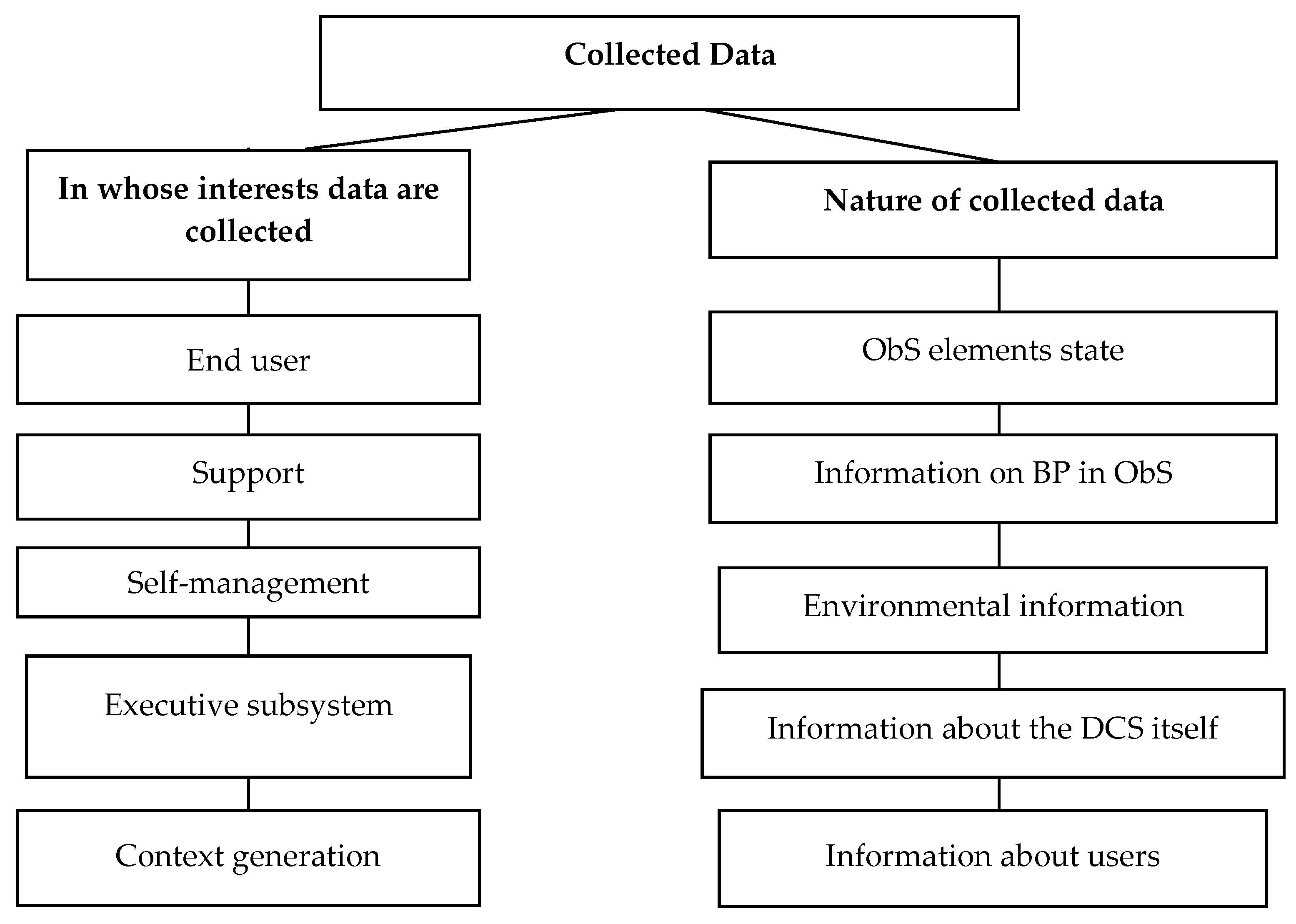
Types of collected data. The classification of data collected in AmIS is given in
Figure 2. Different stakeholders need different data and information. It can be raw data from sensors, information about events, information about subsystems, resource state, users, BP running in ObS, etc.
Key stakeholders and their concerns. The consumers of the information from AmIS can be both humans (end users, system owners, service personnel, etc.) and technical subsystems (executive subsystems, self-management subsystems, etc.). Their concerns and the data they need are shown in
Table 1. One can see that they have different concerns and need information to be presented in different forms. This fact must be taken into account by developers of DCS for AmIS.
The
Table 1 shows that many stakeholders need processed data rather than raw data received from sensors, different groups of observers communicate with the DC system (DCS) on their own domain-specific language (DSL).
4. DC Task in AmIS
Currently, there is a need to reliably, reasonably and promptly assess the information about the state of multi-level distributed SIS, in particular, AmIS, which can be classified as both complex and large systems (with 104–107 elements), taking into account their high complexity, expressed via high structural dynamics and high dynamics of behavior, as well as the complexity of presenting information to stakeholders, considering their roles. The above requires the effective DC procedures implementation.
One of the key problems of DCS development in an AmIS environment is finding the compromise between the high complexity of the AmIS and the strict performance requirements imposed on them. The use of existing approaches and technologies cannot effectively solve these problems, this defines the need for development of new DC technologies oriented on AmIS.
Requirements for modern and promising DCS operating as part of AmIS. In the most general form, the requirements for DCS that function together or as part of AmIS can be determined based on the well known principle of the necessary variety—Ashby [
35], according to which the variety of behavior of the control system should not be lower than the total variety of managed system. With reference to DCS, this principle can be interpreted as a requirement that DCS has a level of intelligence not lower than the ObS level of intelligence. If the intelligence level is lower than that of the ObS, then its ability to collect data about the ObS is limited and one can only solve specific DC tasks. Since AmIS are intelligent systems, and in the long term are cognitive, it is obvious that DCS should also be intelligent and cognitive in the future.
The following requirements should be considered the key ones and the most difficult to implement in DCS for AmIS: (1) the possibility of automatically tracking changes in the structure and behavior of the ObS; (2) requests processing from different categories of observers (stakeholders) who use different DSLs to communicate with DCS; (3) formation of procedures (scripts) that implement DC procedures in conditions of a constantly changing structure and behavior of the ObS.
The following requirements, considered as architecturally significant characteristics, are applicable to DC functions in AmIS.
Performance requirements for DC. Sensor devices capable of measuring a large number of different parameters with small delays. Network performance determines the ability to process large amounts of data collected and then transmit them to consumers.
Resource consumption requirements. The network resources can be power resources of sensor devices, resources of data transmission channels, etc. If there are constraints on power resources for sensor devices, the lifespan of the network is determined by the amount of data received and transmitted. In most cases, DC uses existing channels intended for solving other tasks, including management tasks. Many of the channels have limited bandwidth, which does not allow the transmission of all collected data.
Requirements for the speed of DC and transmission. There may be delays in DC and transmission. Most systems impose strict limitations on the allowed delay time associated with continuous changes occurring in the network. In addition, delays in the network can lead to data explosion, loss of data packets, and other network failures. The considered problems of DC and transmission occur when various types of networks are used, but they are most evident in wireless networks.
To solve the problem of DC in AmIS, the use of a technology based on the model approach (Model Based Technology (MBT)) is proposed. The main idea of MBT is to use the ObS model. The model is multi-level, it is constructed in terms of knowledge (ontologies, knowledge graphs). The model describes the ObS structure and its Business Processes (BP). The model is built and kept up-to-date automatically using the algorithm for synthesizing structural models proposed by the authors’—Vodyaho et al. [
36,
37] and Data Mining algorithms—Aalst [
38]. At the same time, all requests from observers are sent to the model through the representation formation subsystem (human-machine interaction)—Blasch et al. [
16].
The availability of the ObS model allows the implementation of DC technology that ensures compliance with the requirements. The technology includes the steps shown in
Table 2.
5. Conceptual Model of DC in AmIS
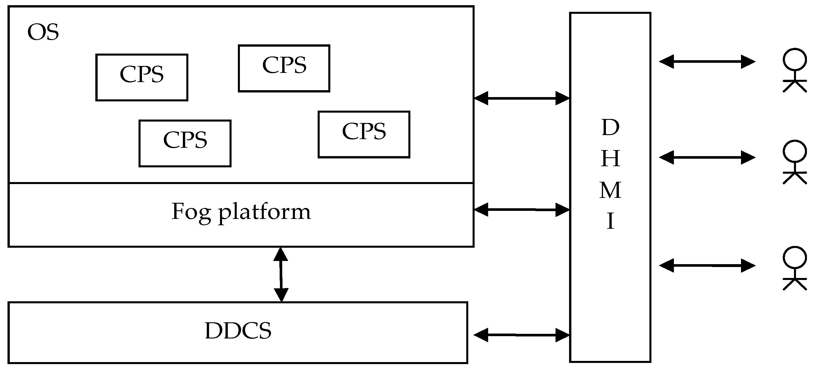
At the conceptual (platform-independent) level, DC System (DCS) can be defined as DCS = <ObS, DDCS, DHMI, Obs>, where ObS is an observable system, DDCS is a distributed DCS, DHMI is a distributed system of human-machine interaction (representation generation), and Obs—observers.
The standard structure of an AmIS that uses DDCS is shown in
Figure 3. The functioning of DCS can be described in terms of four parallel and asynchronously functioning automata (processors) and a repository where data, information, and models are stored. Management is carried out in terms of policies—Strassner; Serrano et al. [
39,
40,
41]. The data processing policy processor generates a script that executes the DC procedure. The policy execution processor is responsible for the generated scripts execution. The model processor is responsible for working with model knowledge. The view generation processor processes user requests for information about the ObS state—Serrano et al. [
41].
The DCS implements the proposed MBT functions as follows. The observer generates a DSL request to the view generation processor, which in turn generates a request to the ObS model hosted in the repository. If data can be obtained directly from the model, it is extracted from the model, converted to the corresponding representation, and sent to the observer. If the model does not contain the required data, then a script is generated using logical inference procedures based on the policies and the model—Vodyaho et al. [
36,
37], which is moved to the policy execution processor, which is essentially a script interpreter.
In parallel, the process of processing information about events in the ObS takes place in time, which is received in the form of logs [
42]. Logs can be generated on the ObS side either on the initiative of the ObS, or by monitoring procedures launched by DCS, or they are a response to requests from the DCS. Information from the logs is sent to the policy execution processor. When the log is received, the policy execution processor starts the corresponding policy, which is executed by the model processor and the processor itself. Policies can be taken from the policy repository, or generated by implementing a logical inference procedure—Vodyaho et al. [
36,
37].
6. AmIS Special Case Model System
According to the model there are two parallel processes: (1) the process which works with users (observers) requests; (2) the process which works with sensors. Both processes work with the ObS model. The DC process is responsible for filling in the model, and the query processing process generates the required views based on the model.
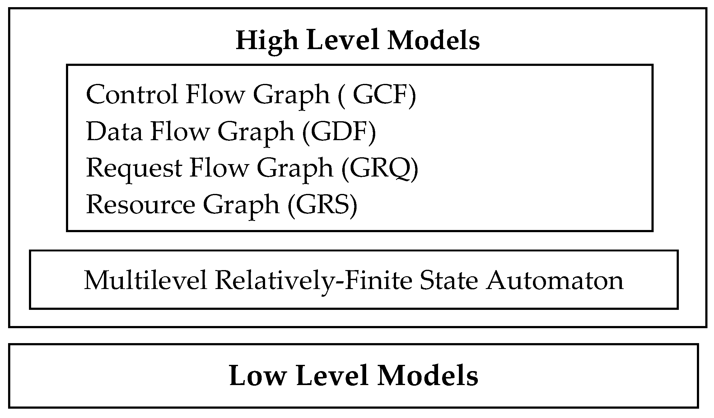
The models used (M) are divided into high level (MH) and low level (ML) M = <MH, ML>. High-level models are models that are used to generate responses to user requests. They also contain the collected data. These models are deployed on the upper levels (cloud and partial fog levels). Low level models are used when creating and executing scripts. These models are located at the lower level (sensor network level and partial fog level). The generalized structure of the models system is shown in the
Figure 4.
High-level models. MH is defined as MH = <G, A>, where G is a graph and A is an automaton. Graph G is defined as G = <GCF, GDF, GRQ, GRS>, where GCF is a control flow graph, GDF is a data flow graph, GRQ is a request flow graph, and GRS is a resource graph. Automaton A is a multilevel relatively-finite state automaton that implements graph control.
Graphs GCF, GDF, GRQ are designed to store information about the BP, and GRS describes the structure of the ObS. GCF describes the sequence of executing operators. This is a traditional graph that Process Mining algorithms work with. Using this graph, one can describe the execution of a certain BP only in terms of the order in which the operators are executed. GDF allows the description of a process in terms of data dependencies. This graph can be useful in solving issues related to the reconfiguration of the BP. GRQ allows the description of the BP in terms of queries, which can be useful when describing, for example, recursive calculations. GRQ allows you to describe the BP in which operators can be created during calculations. GRS is a graph that describes the hierarchical structure of the ObS.
The described MH should be considered as a metamodel, on the basis of which private models can be constructed. For example, if you don’t use recursive mechanisms, you don’t need to use GRQ.
MH can be implemented in various ways, in particular on ontological platforms, as object-oriented structures described in high level language, or as structures described in XML. The preferred option is to use an ontological representation of this model. It is also possible to use knowledge graphs. MH models are quite complex and can be implemented as cloud services. Individual domain-oriented fragments can be deployed in the fog layer.
MH models, methods of their construction and working with them are described in detail in the authors’ publications—Vodyaho et al. [
36,
37]. These models are quite advanced and have a wide range of applications, including those that can be used in DDCS.
Low level models. Low level models are placed at the level of the sensor network and partially in a fog environment. ML models are extremely heterogeneous in composition and structure domain-oriented models. At the lower level (Sensor Layer, Physical Layer) there are sensors, actuators and communication tools, and the controllers and communication tools used at this level are becoming more powerful and allow fairly effective horizontal interaction. At the lower level, you can quickly collect data from devices and transmit the data securely by combining devices into clusters and building a hierarchical network structure. The cluster structure of the network is rebuilt when the location of devices or their state changes.
The cloud layer hosts services that provide DC management and adaptive data processing, which reduces the amount of data transmitted over the network. As a result, the amount of network resources that are spent on DC is reduced.
Cloud Layer can be built on the basis of public, private, or hybrid cloud—Hwang et al. [
14], and is a purely virtual, automatically scalable resource. Cloud Layer is a set of services that is usually quite broad, but often fixed. Applications are built as ecosystems based on these services. The time of access to services is mainly determined by the bandwidth of communication channels. Cloud Layer management capabilities are extremely limited.
Thus, the proposed DC model is a fog oriented model that provides the use of cluster technologies in DCS. The task of its development is to find a way to optimally, in a sense, place elements on levels and ensure effective interaction between them.
7. DC Methods, Algorithms and Protocols Used at the Physical, Network, and Fog Levels
General approach. AmIS are a fairly broad class of SIS that can be targeted at different subject domains. Depending on the purpose and specifics of the requirements, different characteristics may be architecturally significant. For example, for smart home systems, the main characteristic is TCO, while for military systems, the main architecturally significant characteristics are response time and availability (reliability). This circumstance causes a wide variety of methods, algorithms, and protocols used for the AmIS.
In the proposed MBT approach, AmIS and CPS are considered as problem domains, i.e., linked to specific subject areas, and IoT and IIoT are considered as solution domains, i.e., solutions that are not linked to specific areas. IoT and IIoT can be considered as off the shelf technologies used in building CPS.
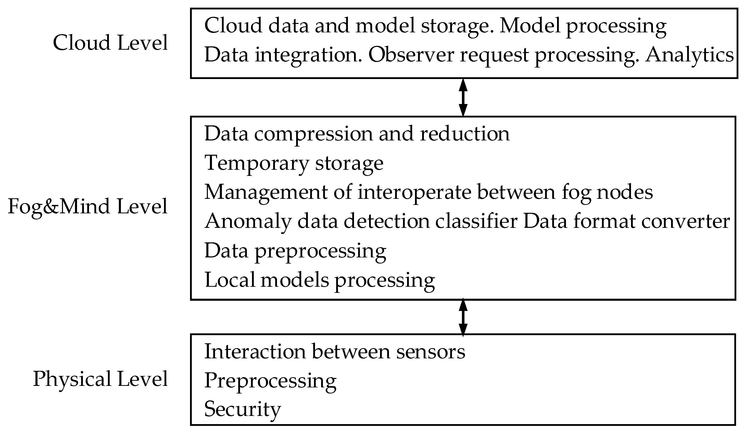
Tasks that are solved in AmIS can be divided into levels in a variety of ways, depending on the specific requirements. A general rule can be formulated as follows: data processing should be as close as possible to data sources, i.e., communication channels are often the bottleneck. The generalized structure of distribution of tasks by levels is shown in
Figure 5.
Physical level. The main function of the physical level is to collect data from sensor devices. Devices may have their own computing resources, or they may not have them. The devices are various wired and wireless sensors that measure the parameters of objects in the physical world. Typical parameters of objects, such as temperature, pressure, etc., as well as specialized ones can be measured.
In the proposed model, DC at the physical level is provided by efficient dynamic data routing. For AmIS conditions, efficient routing can be achieved, in particular, by creating device clusters. The usage of a cluster structure reduces the complexity of data routing tasks, since the overall routing problem is formulated and solved within each individual cluster, rather than on the entire set of network elements. This significantly improves the speed and reliability of DC. The formation of cluster structure of the network involves aggregating devices into groups. In turn, individual groups may be part of larger groups. As a result, a hierarchical cluster structure is formed. When changing device positions, clusters are dynamically rearranged. As a result of rebuilding, the composition of cluster elements, their number, and the number of levels in the formed structure may change. The collection and transmission of data in networks with cluster structure involves the definition of the central elements in each cluster. Devices that are part of a cluster transmit data to the central element of their cluster. Central elements send data through gateways to the fog level for further processing. There may be schemes where the data transfer path from the central node to the cloud nodes passes through the central nodes of neighboring clusters. Detailed algorithms for DC based on building and rebuilding device clusters are discussed in Alkhamisi et al.; Rahman et al. [
24,
25].
Usually, some pre-processing of data is implemented at this level (excluding duplicate data, filtering obviously erroneous data, etc.).
The physical layer is quite vulnerable to attacks by hackers due to the availability of information transmitted over wireless communication channels and has relatively weak security. A significant number of models and methods have been developed and successfully applied in practice to ensure security.
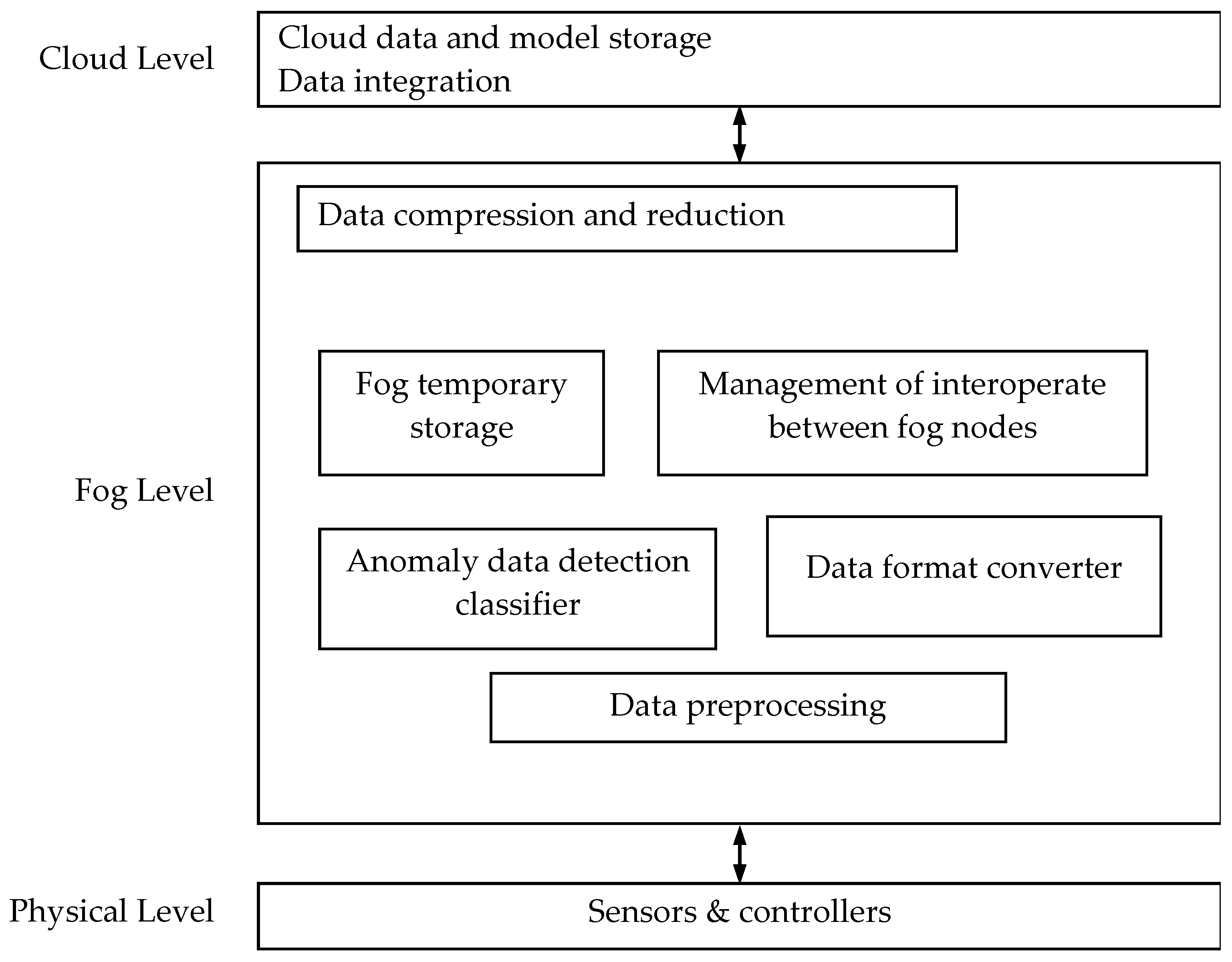
Fog level. The main functions of the fog level are performing computational operations that allow the conversion of the source data streams. As a result of these transformations, the amount of data collected and the amount of data sent to the cloud are reduced. Under AmIS conditions, data transformation processes can be built by applying data classification methods. These methods are based on measures of similarity and difference between data elements. Classification methods allow the definition of data ownership classes. Depending on the data ownership classes, methods for converting data are selected. The structure of DC methods which can be used at fog level is shown in
Figure 6. Typical tasks solved at this level include the following tasks—Maiti et al. [
28].
Data classification. The data classification permits the detection of useful data for the user or for the system according to their interests. The goal of context aware classification processes in the fog is to divide multiple incoming data into required and not required information based on the user’s interests. It is proposed to use such classification algorithms as K-NN, SVM and ID3. For example, K-NN assumes finding the nearest neighbors to the classified elements and predicting their values using the values of the neighbors. If the collected data is redundant or has low accuracy, then they are not used. In the case when data are complete and have high enough accuracy, they are sent to the fog nodes for further processing.
Data format convertion. In the networks, different types of devices are used. They produce a large volume of heterogeneous data which are presented in different formats, in particular, JSON, BSON, CBOR, Msgpack, JSONC, Protobuf, etc. All these different formats are considered as special formats. Using different data formats defines the need to convert data to a uniform format. The common data formatting technique is as follows. The special formats are registered in data collection systems and the corresponding program code for their processing is written. Thus, the gathered data that have one of the special formats can be processed by these systems. After processing, the data is converted to the uniform format. After that it is sent for compression.
Lossless and lossy data compression. The large amount of data needs huge storages and many resources for its gathering and transmission through the network. Therefore, fog nodes are used to compress the data. The proposed technique defines the need to use data compression algorithms such as lossy delta encoding algorithm or bubble sort to sort the dataset. For example, the algorithm can calculate the mean values of two consecutive values of the data set and round them by using the “round” function which removes the fractional parts of the values. Finally, the file with calculated mean values is generated and sent to fog temporary storage or cloud storage.
Temporary storage. In the cases when data must be stored, it is necessary to determine the storage where it is reasonable to place them. In our case there are two types of storages: a cache data storage and a persistent data storage. In the cache, the data are temporarily stored and aggregated. The data are stored until the time of storage is expired. The data that need persistent storage are sent to the cloud service management systems. In the proposed technique, temporary storages such as Redis, SQL, MySQL, SQE and an auxiliary storage pool can be used. For example, Redis can be used as a module for saving real time and frequently used data. Redis can deal with rich data structures such as lists of groups or things, sets of values, hash tables. It can also sort data by weights. Based on the sorted set of values of time or location attributes, it is possible to search records that relate to devices using queries. Furthermore, data records have Identity (ID) and are stored in the associated table list. Therefore, a data record can be searched through its ID. Due to the limited storage capacity and the memory in the temporary storage, a time and memory usage configuration trigger mechanism is used to send the data to the cloud database.
Cloud storage. Cloud storage is used for storing history data. One can update and synchronize data, make regular backups, and provide required information to the fog nodes. There exist many types of storages like a file system, RDBMS, NOSQL, DBMS, DBMS and SQL. Sufficient storage space to store historical data can be provided using the HBase database with HDFS file system or DBMS with NOSQL and XML files in HDFS. In the storage, the defined tables can use indexes based on time, location, type and keyword attributes. The data sent by the fog nodes to the cloud are compressed data. Thus, when the user requests the data, it is necessary to decompress data in the cloud. At the decompression step, the cloud service receives the compressed data file according to the request of the user. Then, the data is decompressed and the file with the decompressed data is sent to the user.
The cloud level. This level usually has almost unlimited resource possibilities in terms of information storing and processing. Currently, applications for intelligent data processing can only be deployed in a cloud environment. Typical tasks that can be solved at this level include the following tasks: cloud data and model storage, model processing, data integration, observer request processing, and analytics.
To date, a lot of different platforms, technologies, algorithms and protocols have been developed to be used while solving typical problems related to the sensor and fog levels—Marques et al.; Boyes et al.; Korzun et al.; Mahmood [
4,
5,
7,
43,
44].
8. Possible Approaches to DCS Implementation
The models discussed above are the conceptual model and can be conceded as metamodel that can be used to create specific models for specific DCS.
There are at least three different approaches to building DCS: (1) DCS can be built on the principle of representation transformation, used in many modern information and control systems; (2) DCS can be built as a context aware system (CAS); (3) DCS can be built as a distributed system with individual elements embedded in the subsystems of the observed CPS.
Models based on the transformations. DCS of this type represent systems collecting data about the state of the BP and subsystems and present them to stakeholders in accordance with their roles. This type of DCS can be represented as:
= <RQ, PRS, D,
, L, TR>, where RQ is a set of requests to perform actions to collect information, PRS is a set of representations of query results, D is a set of data points, TR is a set of transformations. Basically, two tasks are solved: the formation of the DC policy and the formation of views. For example, some modification of the JDL model (Joint Director of Labs data fusion model) can be used as a formal model describing and the formation of views—Blasch et al. [
16].
DCS as a CAS. This model is primarily focused on solving problems related to the situation assessment. A generalized model of CAS can be represented as = <RQ, RS, D, L, PROC, , , Δ>, where RQ—requests for information collection actions, RS—ObS responses, D—points of data retrieval, PROC—processing procedures, L—information about events coming in the form of logs, —current context processing methods, —reference context models, Δ—procedure for determining the degree of contexts proximity. In turn, the DC procedure can be defined as PROC = <PROCp, PROCc>, where PROCp—a set of processing procedures, and PROCc is a set of processing procedures.
DC system as a control system element. In the most general form, the DC model as a separate CPS subsystem can be represented as
= <RQ, RS, D, L, PROC>, where RQ is requests for DC actions, RS is a set of data transmitted to the executive subsystem, D is a set of data capture points, PROC is a set of data capture and processing procedures, and L is an event information received in the form of logs. The behavior of ObS can be described as follows. When working in discrete time, the ObS state is described by the element x of the phase space X = {x}, and its evolution in time is described by the sequence
,
,
. These types of DCS are described in more detail in Tianxing et al. [
45].
The proposed models can be used at different stages of the DCS lifecycle: at the design stage, during the operation (run time mode), or at both stages. In the first case, models are only used as framework elements and DCS are built on their basis. In the second case, the models are used only during operation. In the third case, the same models are used both at the design stage and at the operational stage.
From the technical implementation point of view, the obvious solution is to use SOA or micro-services—Marques et al. [
4].
9. Assessment of the Readiness Degree of the Proposed Technology for Practical Use
The key moment from the point of view of the proposed MBT readiness is the development of the following models and algorithms: structural model synthesis algorithm, BP synthesis algorithm, script synthesis algorithm, DSL of various categories of users and transformation services that support them, representation formation models and services that support them, typical DCS architectural and structural solutions, low level models and services, architectural framework, models and services that support cognition.
Table 3 provides information about the availability of separate MBT elements. Generally speaking, the main elements of MBT are ready for use.
10. DCS Cognitive Capabilities
The term “cognition” broadly defines how a person thinks, makes decisions, solves problems, and learns. This concept is used in such fields as philosophy, psychology, and biology—Johnson-Laird [
46]. Cognitive information systems are usually understood as systems that use cognitive architectures and are based on human heuristic algorithms, which are identified by psychologists and biologists who are often members of development teams. With regard to DCS, a more specific definition can be offered: a cognitivity may be related to DCS’ ability to perceive information about the state of the ObS and the outside world (context), working with the model itself and the model of the ObS and the model of the external world with the ability to learn and accumulate knowledge. Quite often, when speaking about cognitive systems, the focus is on their ability to learn and self-learn. Systems that do not use these models can be defined as simply adaptive or intelligent ones. According to this definition, cognitive systems are a subclass of adaptive and intelligent systems.
Rather similar ideas are developed within the framework of the approach known as autonomous systems—Hwang et al. [
14], the main idea of which is the ability to implement functions related to the implementation of adaptation mechanisms. Usually, in relation to SIS, the concept of adaptability is defined through such concepts as: robustness of software, internal and external adaptation, runtime and dynamic adaptability, resource variability, dynamic reconfiguration, effective adaptation, self-management.
The above adaptation mechanisms can be considered as a tool for building cognitive DCS. From this point of view, cognitive systems can be considered as a further development of adaptive systems and they can be defined as adaptive systems capable of learning, i.e., capable of improving the mechanisms of adaptation inherent in them in the course of functioning. It should be noted that using a model approach to building DCS allows the solution of many problems related to adaptation and self-adaptation.
In relation to DCS, it is possible to speak about at least three aspects of cognition—Vodyaho et al. [
47]: DCS observed system is a cognitive system, DCS as an element of the cognitive system, DCS implements cognitive DC technologies.
DCS system is a cognitive system. If ObS is a cognitive system, then it is natural to assume that the ObS behavior and the structure are permanently changing. Usage of the proposed approach allows quick monitoring of the dynamics of the ObS behavior and structure. This information can be used both for monitoring the ObS functioning and for its training. In this case, the DCS itself may not be cognitive, although it is logical to assume that the use of cognitive DCS is preferable.
DCS as an element of the cognitive system. DCS can be part of ObS as a subsystem responsible for receiving information about the ObS state. In this case, depending on the task of DC, ObS can be either cognitive or non-cognitive.
DCS implements cognitive DC technologies. Building cognitive DCS concerns the possibility of improving the DC procedure through training. The proposed MBT includes two key procedures: the procedure for building and maintaining up-to-date ObS model and the procedure for building a script that implements DC. These procedures are based on inductive and deductive syntheses algorithms−Vodyaho et al. [
36,
37].
11. Case Study
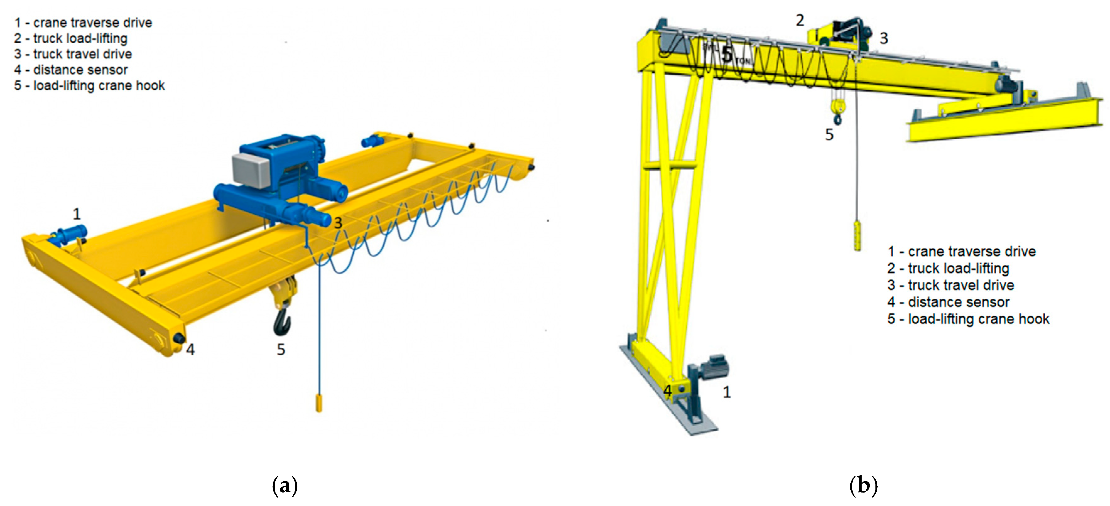
As an example that illustrates the possibility of using the proposed approach in practice, let us consider a DCS from industrial crane complexes that implements elements of reasonable behavior. In this DCS, the previously described MH models and the MH subsystem are located in the cloud, based on a central server. ML models are implemented on the basis of IIoT platform. All the processing in terms of knowledge is performed in a virtual environment. Production sites consist of several monitored shops where bridge and semi-crane cranes are operating (
Figure 7). Two types of cranes are used: single-body (one lifting mechanism) and double-body (two lifting mechanisms).
Figure 7 shows the appearance and structure of the travelling crane. The number of cranes in each shop varies from 10 to 200. Cranes move within a single shop at a speed of about 3 m/s. When working, they can be in different states and can be located in various places with different external conditions, in particular, in places with a high level of electromagnetic interference, etc. The system of such cranes as an observation object is permanently changing, making the data collection much more difficult. For effective DC, the model of the observed system is automatically created and kept up-to-date.
There are two types of sensors installed on the cranes: analog and digital. Analog sensors are used to measure the distances between trolleys (for double-line cranes), between the trolley and the edge of the crane, as well as the length of the rope, the weight of the load, the ambient temperature, voltage and current of the power supply network. The discrete sensors include sensors that determine the extreme upper and lower positions of the hook, the state of the repair gates, the position of the hatch in the cabin, as well as all the fuses in the switch cabinet. Data are collected from all sensors at 250 ms intervals. The total number of measured parameters on each crane is about 560. The total amount of data received from each crane per month is approximately 2 TB.
Based on the data received from the sensors, the tasks of assessing the cranes states, ensuring their operability and safety are solved. In operating mode, data on the state of power supply circuit fuses must be collected at a frequency of at least 2 Hz, from load mass sensors—at least 2 Hz, from engine temperature sensors—1 Hz or more. When the crane is idle, you only need to collect information about the state of the power supply and the ambient temperature. At data collecting, it is necessary to ensure a less than 5 s delay in transmitting data from the cranes to the workplace of the chief mechanic.
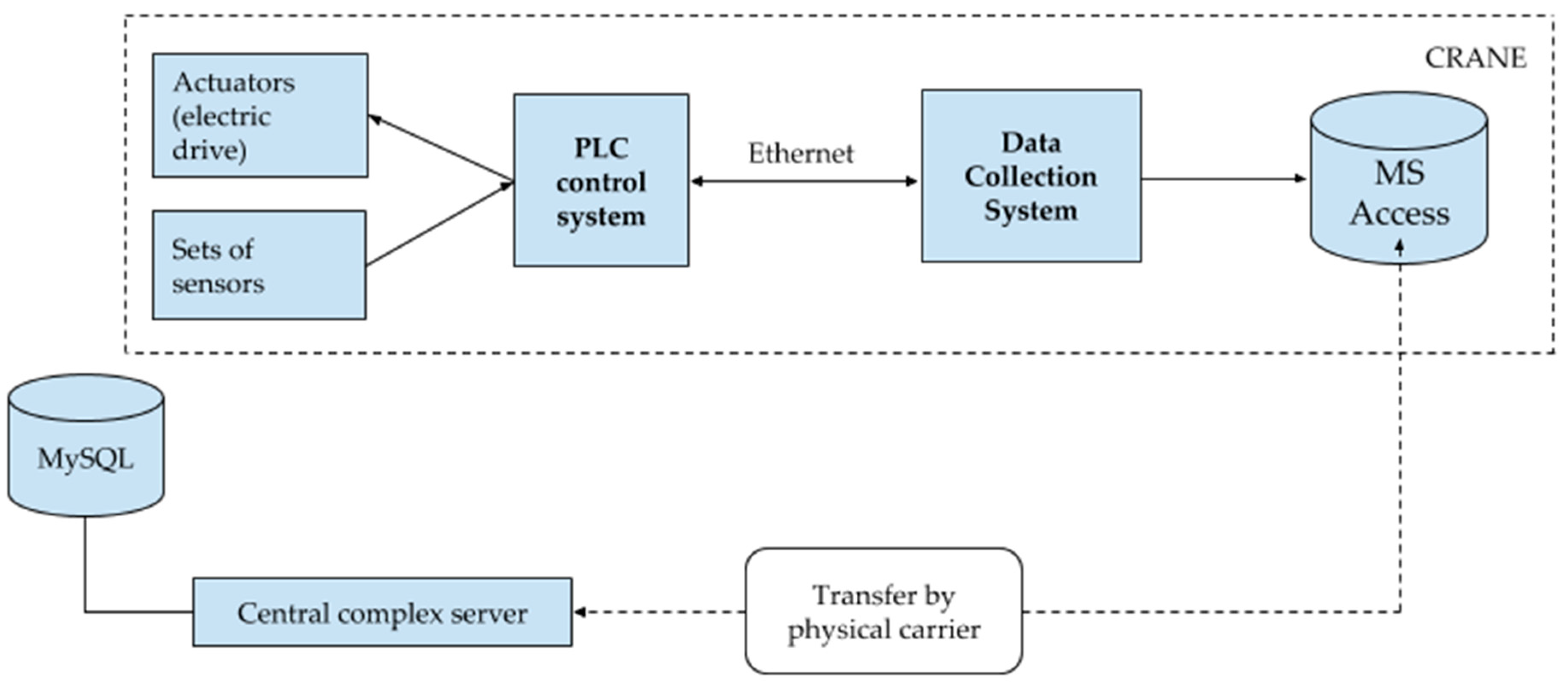
A typical block diagram used for DC at crane complexes is shown in
Figure 8. The DCS is a distributed system that includes equipment installed on cranes, as well as the hardware and software complexes of the crane operator and a central server. The DC process is divided into two stages: DC from sensors carried out on the crane, and data transfer from the crane to the central server. The composition of the collected data does not change.
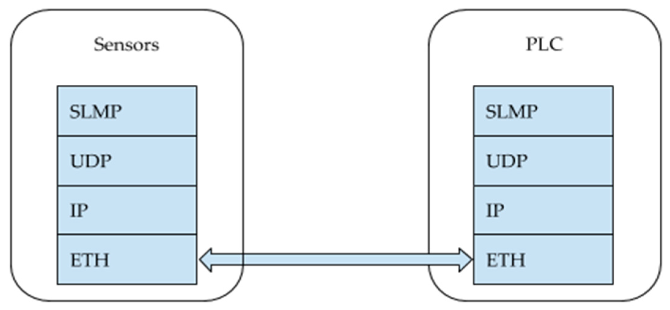
Data is collected from sensors in real time. For DC, MITSUBISHI MELSEC-Q [
48] series Industrial Programmable Logic Controllers (PLCs) installed on the crane are used, which provide control of the crane, as well as a buffer for data collected from sensors. The internal memory of the controllers is accessed via the SNMP protocol. To transfer data from the PLC to the fog node, an Ethernet link with a bandwidth of 100 MBit/s is used. This channel also transmits commands to the control mechanisms of the crane. The channel provides high-quality communication, but has limited bandwidth. Overloading the channel can lead to the loss of control commands and cause failures in the operation of the crane. Data is collected by the Odroid C3 single-board computer. Odroid C3 has sufficient computing power to organize the survey of PLC registers at the required frequency. The organization of communication within the OSI model between the PLC and Odroid C3 is shown in
Figure 9. Collected data is placed in the MS Access database, which is installed on the computer.
Data transfer from the Android database to the central server can be carried out via a WiFi connection channel or by the operator. The use of the Wi-Fi channel is significantly difficult due to the large number of electromagnetic interference from welding and alternating current sources installed in the shops. On average, the ratio of lost and transmitted packets is 1:5. As a result, data are sent to the central server with a significant delay, and some of the data may be lost. DC by the operator involves the use of a tablet that is part of the operator’s system. The software installed on the tablet allows receiving data from the Fog node’s database over the radio channel and cache them on the tablet. The range of the radio channel does not exceed 20 m, which requires the operator to be in close proximity to the crane.
The considered scheme creates a large load on the Ethernet data transmission channel, and also does not provide operational data transfer to the central server. Application of the proposed technology allowed: (1) reduce the load on the main data transfer channel from the PLC to the Fog node’s database by using fog computing technology; (2) improve the speed of data transfer from the Fog node’s database to the central server in unstable communication conditions without operator participation by using cluster technologies.
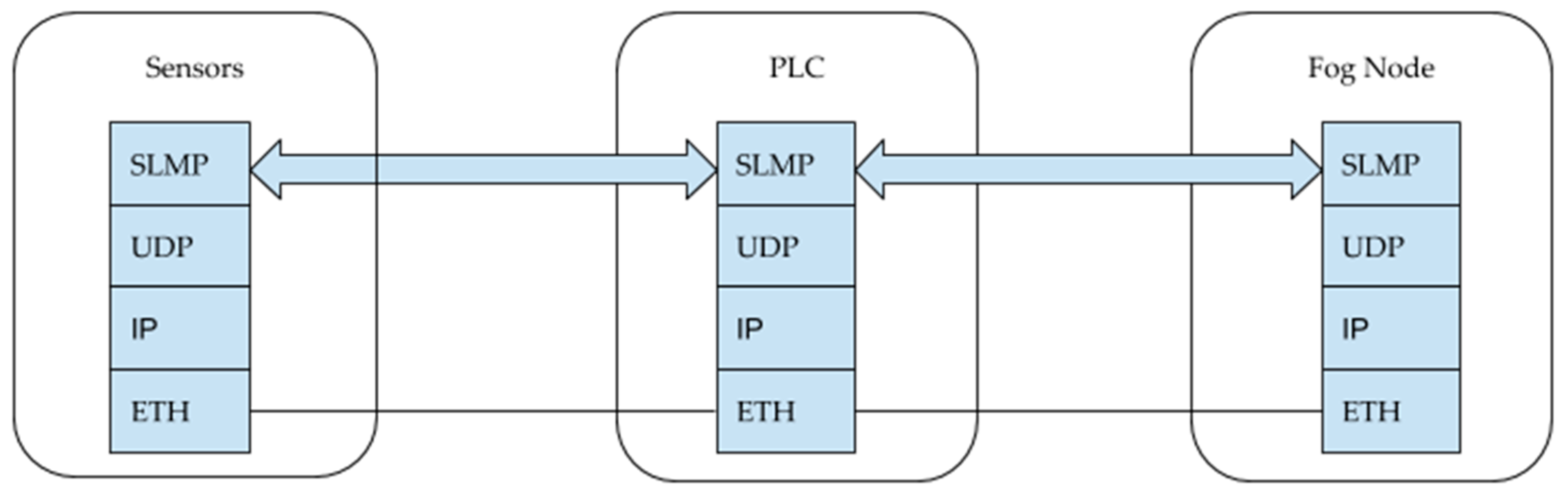
An additional intermediate link (fog node) was developed to collect data on the crane) “ARM CPU”, which provides DC management (
Figure 10). Organization of communication between sensors, PLC and fog node is shown in
Figure 11.
A priori information on the object from which the information is collected, the types of sensors installed on it, and the dynamics of changes in the measured values are used to reduce the volume of collected and stored data at fog nodes. When data is collected using discrete sensors, changes in the measured values are recorded. The initial scheme assumed measurement of parameter values with a certain sampling step, representation of data in binary form and their storage in the database. To reduce the data stored in the database, the new scheme detects changes in values, identifies ascending and descending fronts, and records the time when these events occur. When collecting data using analog sensors, dynamic changes in the sample rate are provided depending on the state of the crane. The reduction in the sampling rate occurs after the system analyzes the rate of change of the measured value over a fixed period of time.
Two models were constructed to quantify the benefits of using the developed fog nodes in DC. The first model was used in production systems earlier, and the second model is a new model proposed for DC in AmIS. DC models have the following parameters: Q—number of PLC registers for data storage; S—register size (bytes); —sampling rate (Hz).
When using a traditional DC scheme, the amount of data collected and processed is: . The development of fog nodes and the data transformations performed on them, based on the use of a priori knowledge about the types of data being processed and the nature of their changes, made it possible to transform the traditional model as follows: where . To account for random influencing factors, random variables are included in the model . Then the model takes the following form: The amount of data collected when using fog nodes is:
The values of the model parameters are determined by the design features, the electrical scheme, and the placement of cranes in the shop. For a typical PLC complex, the model parameters have the following values: Q = 560, S = 2 bytes,
= 10 Hz.
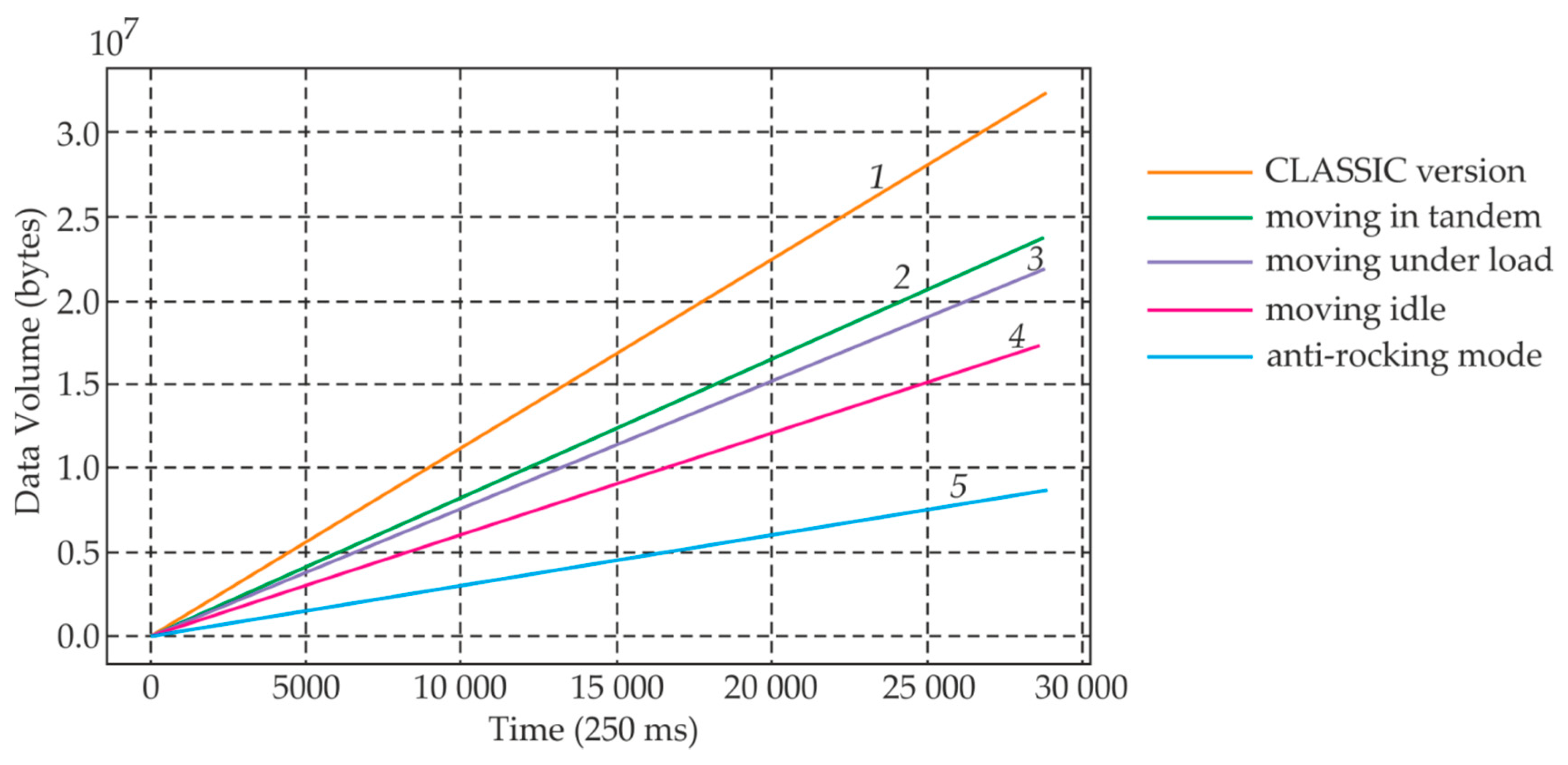
Figure 12 shows the total amount of data transmitted in various modes of operation of the crane at an interval of one month when using the classic version (1—for all modes) and the proposed fog version (2, 4, 5—moving in tandem, under load, idle; 3—anti-rocking mode). Graphs are constructed for the main operating modes of travel/semigantry cranes.
The analysis of
Figure 12 shows that the proposed fog version in all modes is more economical in terms of the amount of transmitted data.
The idle mode corresponds to the operation of the crane’s drive mechanisms in an unloaded state (no load on the hook). When the crane is operating in this mode, an incomplete set of sensors is used for control. The number of digital sensors used is 40% of the total number, and the number of analog sensors is 30%. In the mode of moving under load, the operation of the crane’s drive mechanisms provides for the presence of a load on the hook. The number of discrete sensors—60%, analog sensors—70%. Tandem mode is a mode for cranes with two lifting mechanisms. In this mode, simultaneous synchronous movement of cranes is performed. This mode is used when moving large loads. The number of digital sensors used is 90%, analog—70%. Moving in the anti-rocking mode is used to reduce the amplitude of the load swinging on the cable. The number of digital sensors involved—75%, and analog sensors—90%.
The average indicators for reducing the volume of data transmitted over the network, calculated based on data obtained over a six-month interval, are shown in
Table 4 and
Table 5.
Table 4 shows the calculated indicators for different operating modes of cranes.
Table 5 shows the obtained estimates of the effectiveness of the methods used to transform data on fog nodes.
Thus, the use of the proposed fog-oriented DC scheme, which provides for the use of fog nodes, allowed the reduction in the volume of transmitted and stored data, reducing the load on the Ethernet data channel. The implementation of the developed scheme at the enterprise made it possible not to purchase new expensive industrial data storage devices that allow saving slices of PLC registers with high frequency.
The traditional DC scheme involves direct data transfer using Wi-Fi. The Wi-Fi communication channel in the shops has low reliability due to the high level of interference. The data transfer rate is inversely proportional to the distance to the access point. Data transfer to the server starts when the threshold value of accumulated data is reached. In this scheme, the data transfer rate is calculated as where k—coefficient of amplification—transmission rate.
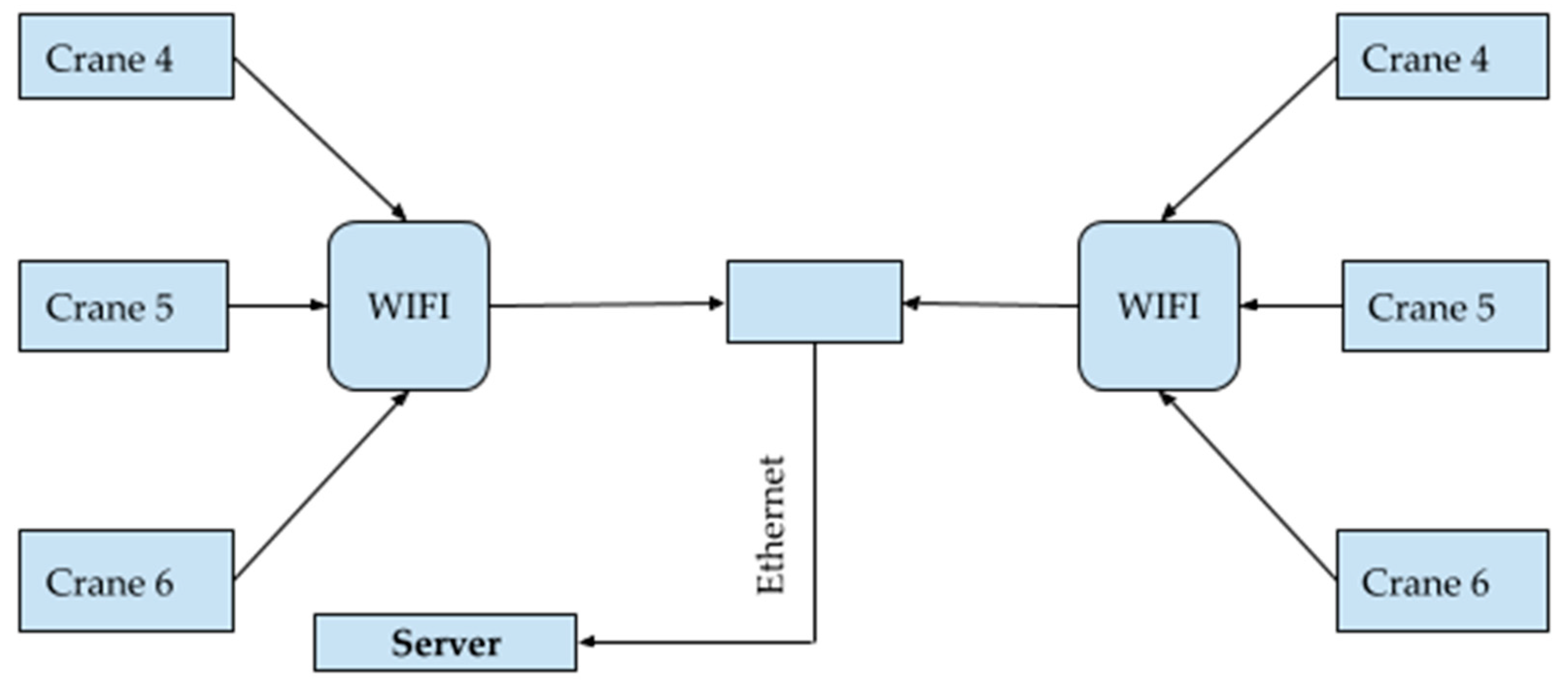
To ensure fast and reliable DC without involving an operator, a cluster scheme for collecting data from cranes was developed. Wi-Fi access points that act as relay nodes are installed in each shop in the repair areas. When a certain amount of collected data is reached (250 MB), data is transferred from the crane to the cluster head element (the crane with the minimum distance to the access point). If it is not possible to communicate with the cluster head element (no line of sight), data is transmitted through nodes (cranes) located in the visibility zone.
Access points are connected to the in store network via Ethernet. When the crane is moved to the repair area, the crane data are transmitted to the relay node (Wi-Fi access point) (
Figure 13).
The following model was used to evaluate the efficiency of cluster data transfer from cranes to the central server. The data transfer rate between the cranes is inversely proportional to the distance between the transmitters. Let —vector of crane speeds at time t; —vector of crane coordinates at time t; —number of the crane that is the “leader” of the cluster. Then the distance vector is calculated as where —the distance along the y-axis. Given that is the vector of transfer rates at the time of for each crane, where is the amount of data left for transmission. Thus, when data is fully transmitted to the cluster leader, the following condition will be met: where —vector of the amount of data remaining to be transmitted. The total time of data transfer to the “leader” of the cluster can be obtained as follows: where i is where the condition is met: . Transferring data from the “leader” of the cluster, on the central server calculated by the formula: where L is the distance to the transmission time t; is the speed of the crane, the “leader” of the cluster; is the amount of data, each crane, you want to transfer to the server; —fixed speed of transmission from the access point to the server.
The speed of data transmission was evaluated for three typical shops. Shop No. 1 parameters: Ethernet speed—10 MBit/s, Wi-Fi speed—from 1–10 MByte/s, average level of electromagnetic (EM) interference—50 dB. Shop No. 2 parameters: Ethernet speed—100 MBit/s, WiFi speed—from 1–10 MByte/s, average EM interference level—30 dB. Shop No. 3 Parameters: Ethernet speed—1 GBit/s, WiFi speed—from 1–10 MByte/s, average EM interference level—15 dB. Summary data for the three shops are shown in
Table 6.
Table 6 shows that cluster data transfer has significantly improved the speed of data transfer from cranes to the central server. This increase in efficiency allowed the quick identification of problems that occur on equipment installed on cranes, reducing the likelihood of serious crane failure and production downtime. This solution is applicable when the signal-to-noise ratio in the channel is not less than 40%. From the point of view of the level of robustness, the proposed solution is not inferior to the currently used approaches.
The main advantage of the proposed approach is that the system can operate in the presence of high level of interference. The main disadvantage is the increased complexity of the system due to the appearance of Fog nodes.
The described above system is only one of many subsystems of big industrial AmIS, which realizes low level models. High level models are deployed in the cloud. They use knowledge graphs and ontologies as platforms for high level models implementation. The presented example allows imaging of the level of complexity of modern industrial AmIS and, accordingly, the level of complexity of their models, and allows one to assess the possibilities of intelligent technologies usage at a fog level.
12. Conclusions
The DC technology proposed in this paper is intended for use in CPS based on the AmI concept for various purposes. The use of models in DC systems has been known for a long time and finds practical application. A distinctive feature of the proposed technology is that models are built and adjusted automatically. It allows the avoidance of involving experts in the process of building and maintaining up-to-date models, and reduces the delays in building models and eliminates errors in their building. Excluding an expert from the model building process is especially important for low price AmIS. Thus, the proposed technology opens up prospects for solving two important tasks for AmIS: reaching a new level of complexity of the created AmIS and expanding the scope of their application by reducing the TCO by excluding humans from the process of keeping the model up-to-date.
The following results are the main ones:
The features of AmIS constructed on fog platforms;
A model approach to the development of DCS, focused on the use of AmIS, which can be attributed to both the class of complex and large systems;
Private DC models;
The specifics of DCS AmIS operation at the low level.
Directions for further research include the development of the architectural framework which can be used for practical needs by AmIS developers. In order to do it is necessary to develop procedures of adaptive mechanisms realization in distributed Fog and Mist environment. It would also be useful to include machine learning services into the framework under development.
It should be noted that the expected transition to cognitive systems will make the task of DC even more complex and problems can only be solved using a model based approach that can be applied in a variety of subject domains. However, the use of the proposed technology in relation to DC in cognitive systems may not be effective enough. The authors associate the further development of the proposed technology with the use of cognitive models.


