Article

A Path Planning Strategy with Ant Colony Algorithm for Series Connected Batteries

1
School of Mechanical and Electrical Engineering, Guangzhou University, Guangzhou 510006, China
2
School of Electrical Engineering and Automation, Harbin Institute of Technology, Harbin 150001, China
*
Authors to whom correspondence should be addressed.
Electronics 2020, 9(11), 1816; https://doi.org/10.3390/electronics9111816
Submission received: 5 October 2020 / Revised: 22 October 2020 / Accepted: 29 October 2020 / Published: 2 November 2020
(This article belongs to the Section Computer Science & Engineering)

Abstract

:
This article presents a path planning strategy with ant colony algorithm for series connected batteries. The motive of this paper is the increasing need for efficient and fast equalization for Lithium-ion batteries. There are many great papers on the design of the equalization circuits. However, they lack the part of path planning strategy for the balancing circuits. To solve this issue, we adopt the graph model to represent the balancing paths among different battery cells and then construct two optimal models based on the best efficiency and speed, respectively. Finally, ant colony algorithm is used to solve these two models. This makes it possible to achieve different goals according to the practical operating conditions. We validate the function of the proposed path planning strategy through an example of 13 series connected battery balancing system.

1. Introduction

To provide adequate/sufficient power rate for the systems such as uninterruptible power supply, electric vehicles, etc., the power cells are usually used in series connection. Lithium-ion battery is a good choice for its high power and energy density, high cell voltage, low self-discharge rate, no memory effect, and being environmentally friendly [1,2,3,4,5]. The imbalance of the voltages among the battery cells are caused by many reasons, such as the difference in the charge–discharge stage and the internal impedance. Consequently, the whole capacity of the battery pack is shortened by the imbalance, and even damaged. It is of significance to equip a balancing equalizer or system to the battery packs [6,7,8].
The affected factors of the balancing system performance is decided by the optimal strategy when the balancing circuit structure and variables are fixed. Currently, there are many intelligent algorithms that can be used for path planning; for instance, the neural network algorithm, grid calculus, artificial potential field algorithm, and genetic algorithm, etc. [9,10,11,12]. The neural network algorithm does well in self-learning at the expense of large-scale network structure, and the grid calculus is good at real-time control at the cost of lacking global information and being trapped in local optima [13,14]. Moreover, its neuron threshold changes with time in multiple obstacles and dynamic environments. Genetic algorithm has good global search ability at the cost of very large searching space, and also the model must be continuously re-established with the changes of the environment. The grid pattern can clarify the best path, but the mesh density and environment have an effect on its efficiency.
The ant colony optimization algorithm is developed by Doctor Dorigo, which is an intelligent search algorithm by long-term tracking the behavior of the ant colony. It is a probabilistic algorithm that is used to solve computational problems, and it can be achieved by finding the best path through graphs. The main characteristics of ant colony optimization algorithm are positive feedback and parallelism [15,16,17,18,19]. At present, the algorithm has been widely used, from TSP to data mining, telecommunication route optimization, robot path planning, deep learning, image processing, secondary distribution, and has achieved very good results [20,21,22,23,24].
This paper presents a path planning algorithm with ant colony algorithm for series-connected batteries using Graph Theory methods to maximize the balancing efficiency or speed under safe operating conditions. The remainder of this article is organized as follows. Section 2 presents the digraph model of a two-layer balancing system. Section 3 then describes the balancing path planning problem as an optimization problem under different operation conditions. Section 4 explains the main procedures of the proposed path planning strategy. Then comes with the simulation results with different balancing goals for 13 series connected batteries. Finally, Section 6 summarizes the article’s conclusions.

2. Two-Layer Balancing System

2.1. System Structure

A two-layer equalization-system structure is proposed to step up the balancing speed and reduce systematic complexity as shown in Figure 1. The battery packs composed by many cell units in this paper are power cells and each cell unit consists of many battery cells. The battery cell can achieve direct equalization through the bottom equalizer and the cell unit can achieve direct equalization through the up equalizer. There is a need to balance more than two battery cells simultaneously to acquire faster balancing rate and higher efficiency when imbalanced situations are complex. Therefore, it is quite necessary to find a path planning strategy based on optimal algorithm to increase the balancing rate and reduce the energy loss.
In order to analyze and design easily, we make the following assumptions in the systematic mode [25,26,27].
(1)
All the switches are considered identical including the parasitic parameters and energy loss coefficient.
(2)
Equalizers of the same type have identical energy loss coefficient while they differ of different types.
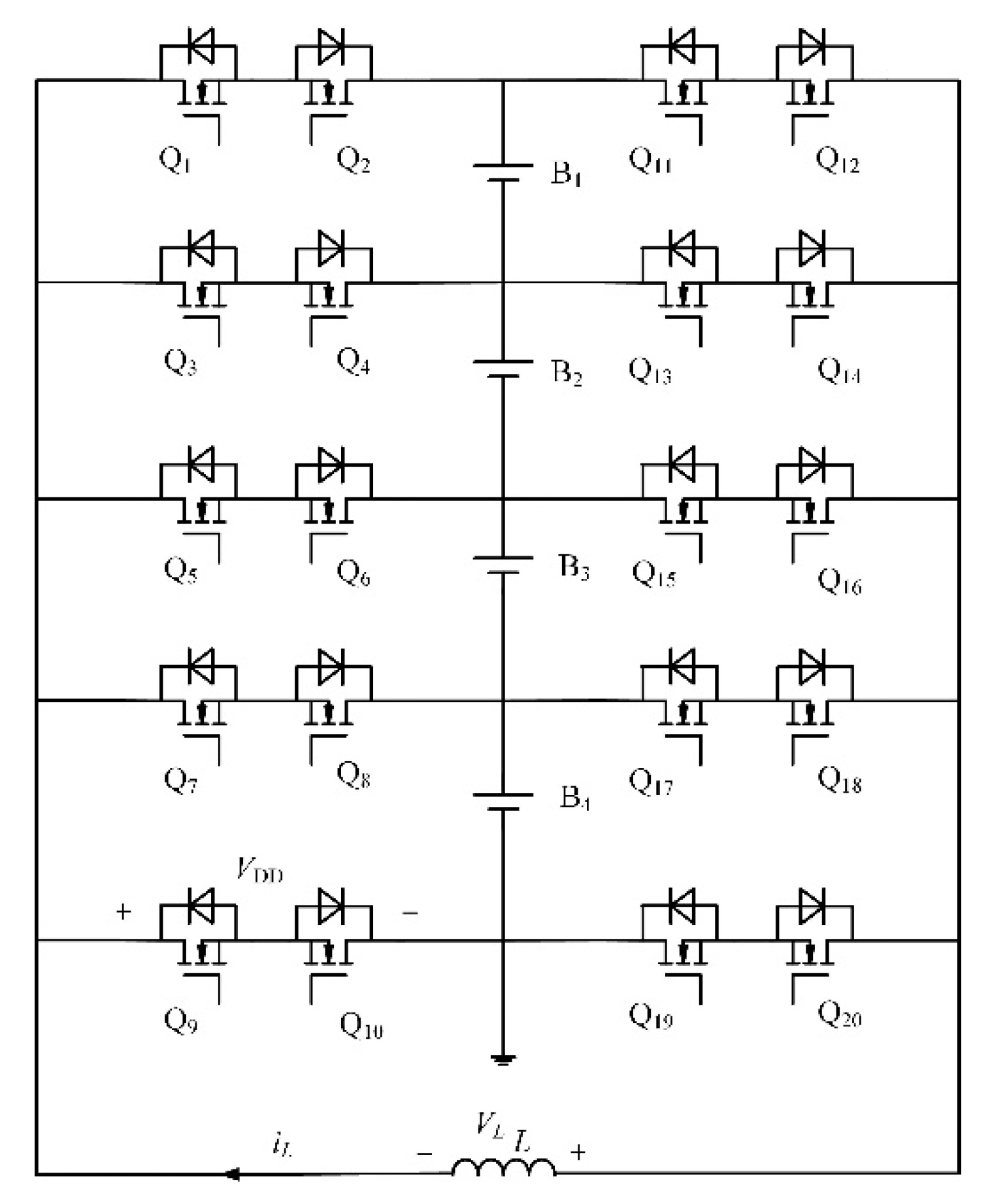
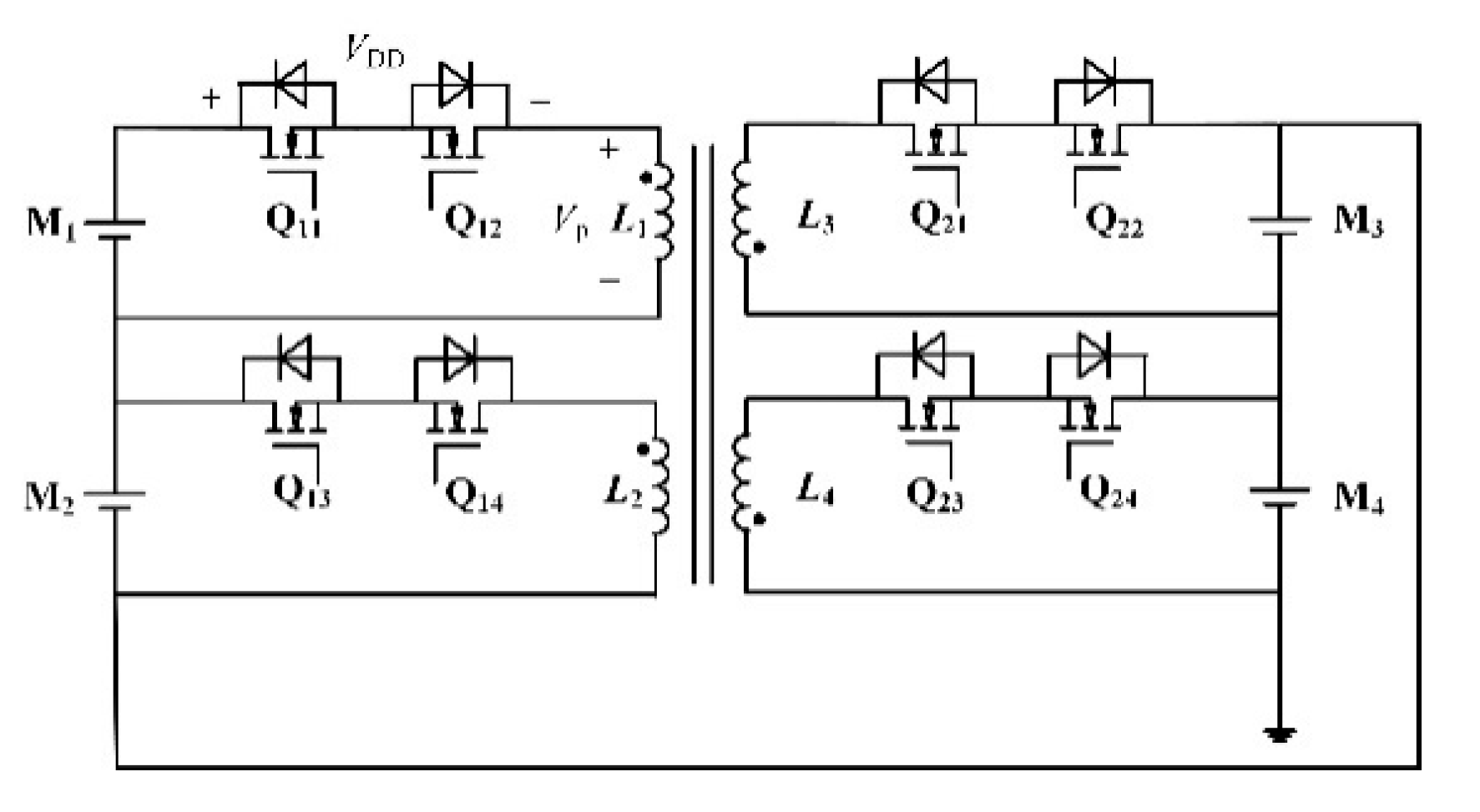
A flying inductor structure is adopted by the bottom equalizer where the switches Qk,i are the low on-conduction loss bi-directional switches as shown in Figure 2. The energy can be directly transferred from the source battery to the target one through the common inductor. A multi-winding transformer structure is adopted by the top equalizer as shown in Figure 3, which can guarantee the direct energy transformation between any two cell units.

2.2. Graph Model for Two-Layer Balancing System

The main circuit elements are needed to be defined such as the batteries, switches, energy storage elements, etc., in Figure 1 to obtain the digraph of the two-layer balancing system.
(1)
Digraph G = ( N , E ) is a graph with a set of N nodes, E directed edges and ordered pairs of different nodes.
(2)
Target node is the terminal node of the energy flow path. It can be either the start point or the end point of the energy flow path. In the balancing system, the energy storage units are defined as the target nodes such as the batteries or the supercapacitors.
(3)
Intermediate node is the node that stores energy temporarily which corresponds to the energy storage element in the equalizer like a capacitor, inductor or transformer. There is a coefficient η stored in conversion matrix, which represents the energy conversion efficiency for each intermediate node. It is considered identical of the same type.
(4)
The graph can be represented as an n × m matrix through the adjacency matrix where the nodes in the digraph constitute the row and the edges compose the line. There are only two non-zero elements in the row corresponding to arc (i, j) where it is −1 corresponding to the row of node i and it is 1 corresponding to the line of node j.
(5)
The real-valued function f (i, j) represents the net flow in the arc (i, j). It can be considered as the number of a commodity, which can be positive or negative. It is worth noting that the net flow in arcs needs to obey the conservation law at each node. As for the intermediate node, the total net flow into the node should be equal to that out of the node without considering the loss during the conversion process. When it comes to the target node, the source battery has more outflow and the target one has more inflow.
The matchup between the balancing system and its digraph model is shown in Table 1. Figure 4 is the updated Figure considering the above corresponding relation where the circuit elements are replaced by the nodes and edges. Each equalizer which is represented by a dotted cycle consists of one intermediate node and k target nodes. Each target node is connected to one intermediate node and two edges. There are k × mm + 1 target nodes, m + 1 intermediate nodes and m × (k + 1) edges when the number of the bottom equalizers is m. We take a 13 series connected battery pack, which is divided into four groups with four batteries in each group for example. It can be obtained that there are 13 target nodes, 5 intermediate nodes and 56 edges in the digraph model. It can also be found that the transmission path of any two target nodes must go through at least one intermediate node. Each type of intermediate nodes has a unique power conversion factor which is stored in the conversion coefficient matrix, and each edge has a value which is stored in the incidence matrix representing the connection status of the nodes and edges. The initial value in the incidence matrix can be got according to the connectivity. It is 1 with direct connection, otherwise it is 0.

3. Balancing Problem Formulation

3.1. Balancing Rules

When imbalance that is quantized by the instantaneous maximum voltage difference of the battery pack is detected, the balancing system starts to respond. That is [28,29,30],
Δ ( t ) = max { abs ( v i j ( t ) mean { v i j ( t ) } ) , i [ 1 , m ] , j [ 1 , k ] }
where v i j is the eigenvalue of the jth battery in the ith group and it can be represented by VOC which is either the voltage or the state of charge (SOC). v i j can be obtained by real-time measurement in the actual balancing system and pre-determined in the following simulation. Δ ( t ) reveals the maximum absolute difference between the amplitude of each battery cell and the mean value of the battery pack.
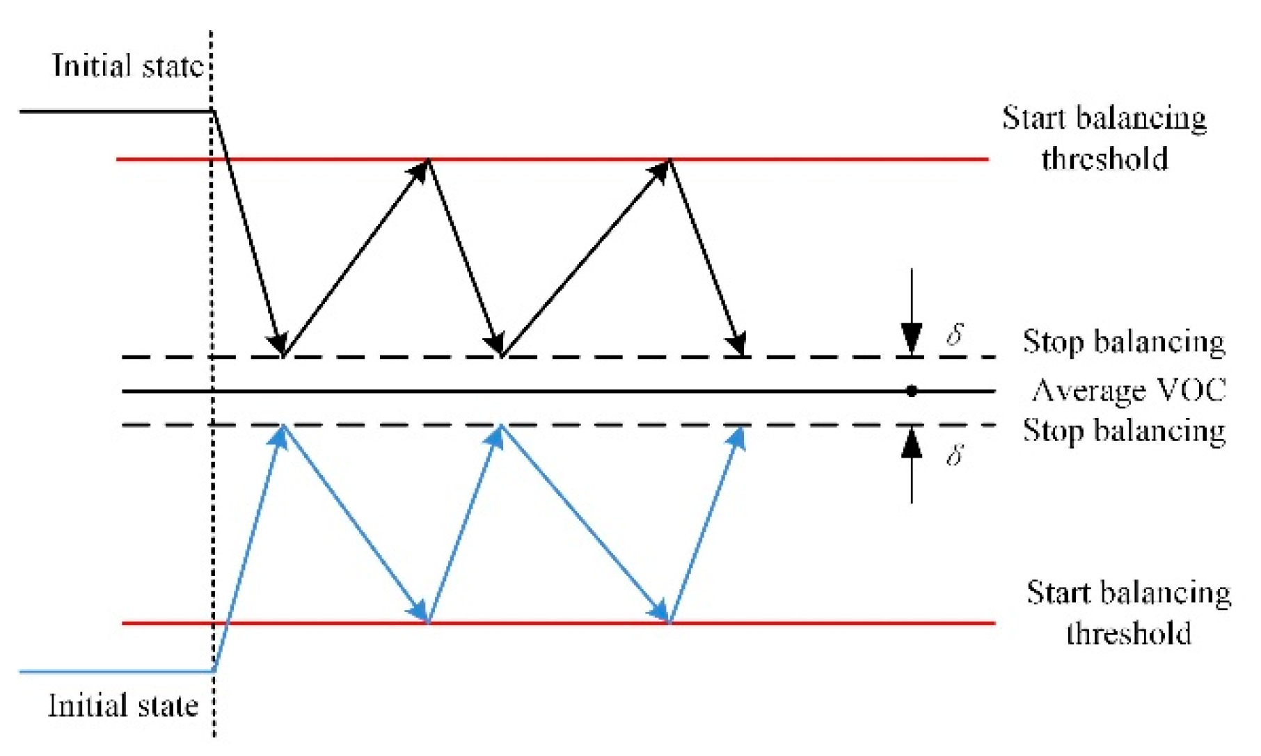
The balancing process starts when the measured maximum absolute difference Δ ( t ) is more than the given threshold C TH . The equalization can be achieved through over-equalization and hysteresis control strategy. That is, the balancing process is stopped when the maximum absolute difference is lower than δ, otherwise, the above balancing process is repeated until the VOC is within the accuracy range. The balancing system acts according to the principle of Figure 5.
According to the experimental results of the literatures, it shows the self-recovery characteristics of lithium batteries. It can be concluded that there are some errors between the open circuit voltage and the actual characteristics. The over-equalization strategy is adopted to avoid the waiting time to speed up the equalization rate and the hysteresis control can also improve the reliability of control.

3.2. Best Balancing Efficiency Model

The balancing problem can be interpreted as a path planning problem where the optimal object is determined by the actual condition either maximum balancing efficiency or minimum balancing time.
It is expected to get best efficiency when the battery pack is idle and then the balancing problem can be interpreted as a constrained optimization problem to improve the balancing efficiency as much as possible. In this way, it can be equivalent to a shortest path problem in order to plan an energy transfer path resulting in least energy conversion times and number of switching.
The balancing efficiency can be defined as [31]:
e f f = 1 e n e r g y   l o s s   i n   t r a n s m i s s i o n e n e r g y   r e d u c t i o n   o f   s o u r c e   c e l l s
The total loss of the balancing process is defined as the energy loss during transferring consisting of energy loss during conversion and switching loss. The energy reduction in the source battery is equal to the energy difference of the target battery before and after equalization.
To implement the algorithm successfully, the total equalization efficiency is expressed through each efficiency of the balancing path denoted as effp. The effp can be signified by the lumped balancing efficiency each time as effc.
e f f p i = Π j = 1 m e f f c j
where e f f p i is the balancing efficiency of the ith balancing path and m represents the conversion times.
Then, the total efficiency during balancing process is
e f f = 1 i = 1 n ( f a i × ( 1 e f f p i ) ) i = 1 n f a i
where f a i is the power flow of the ith balancing path.
To achieve the best equalization efficiency, the balancing cost is defined according to the energy loss during balancing process. The cost function can be defined as [31].
Cost function:
min i = 1 n f a i ( 1 e f f p i )
Restrictions:
Target node:
| v o v oavg | C TH
v i s v i d > 2 m ε
Intermediate node:
a O p f a = μ a I p f a
where v o is the VOC after equalization, voavg is the average VOC of the battery pack. vis and vid are the VOC of the start and destination node of the ith balancing path, respectively, in which the energy flow converts m times. ε is the VOC loss and fa is the energy flow of each edge. Ip are a set of edges that flow into node p while Op is a set of edges that flow out node p. μ is power conversion index of the intermediate node.

3.3. Best Balancing Speed Model

When a serious imbalanced situation occurs in the series battery pack, it is required that the balancing system can respond quickly to improve the performance of the battery pack. Therefore, it needs to be quickly balanced to shorten the balancing time so as to prevent the battery from overcharging or undercharging.
According to the law of electric charge conservation, the balancing time can be expressed as
t = Δ Q I o = C × Δ S O C I o = C × Δ S O C × V B P o C × Δ V k I o
where △Q is the charge variation, Io is the average balancing current, C is the capacity of the battery, Po is the output power, △SOC is the variation of the state of charge, △V is the voltage differences of the batteries, K is the relevant coefficient between the state of charge (SOC) variation and voltage variation, VB is the voltage of the battery.
When equalization is prioritized with the fastest balancing speed, the cost function for the optimization problem is
min t = min i = 1 n C × Δ V i k I o i
Subject to
| v o v o a v g | C TH
v i s v i d > 2 m ε
where n is the energy conversion times.

4. Path Planning Strategy

4.1. Definitions of Some Matrices

The proposed algorithm needs to measure the characteristic parameters of the batteries and judge their state to balance the circuit in time. To record the state of the balancing system and indicate the changes in the system topology, some definitions are made:
(1)
Demand matrix (D): It is a row vector that contains the VOC difference.
(2)
Unit priority matrix (Lp): Its first column contains the unit index and the second column shows the unit priority.
(3)
Edge flow matrix (F): It is a row vector that contains the energy flow of each edge.
(4)
Edge state matrix (Ys): It is a row vector where it is 1 if the edge is chosen, otherwise, it is 0.

4.2. Principal Sequences

The specific implementation of the algorithm in MATLAB is as follows:
(1)
Definitions of digraph matrices: the node-edge adjacency matrix and demand matrix are defined and initialized according to the status of the equalizer.
(2)
Imbalanced status detection: it is of great significance to estimate the batteries’ state according to their VOCs. Once one or more imbalanced nodes are detected, update the demand matrix D according to the calculated power of each node. The demand matrix D is assigned a negative value if the battery cell is overcharging, that is, its VOC is higher than others’. Otherwise, D is assigned a positive value.
(3)
Label edges weights: test the edges around the imbalanced nodes and label each edge on the basis of energy transmission efficiency.
(4)
Route selection: it is a path that meets the objective of the algorithm and minimizes the energy loss during transmission simultaneously. It should also guarantee each battery cell’s VOC within acceptable range. It is necessary to sum up the values of each row gained by multiplying the flux of each edge by the incidence matrix.
(5)
Feasibility testing: Update the distribution of new power flow in the digraph once a scheme is chosen. The distribution is decided according to the overlap of weights which influences the balancing speed.
The specific implementation process of the balancing algorithm is shown in Table 2.

4.3. Solving Steps with ant Colony Algorithm

When using the ant colony algorithm to solve the path planning problem, the problem is usually equivalent to a graph G = ( C , L ) . The node set C is given by the battery group and its position in the problem description. The connection edge set L is the complete connection between the nodes. In general, the process of balancing from the source cell to the target one can be described as a process in which ants are guided by pheromone and local heuristic information and crawl on the graph. When ants crawl, they must also comply with certain restrictions to ensure that they have a feasible solution.
In the ant colony algorithm model, the total number of ants is m and the ant individual is k, then k = 1, 2, …, m. The number of batteries in series connection is n. It is necessary to sort the n batteries from 1 to n when artificial ants build a feasible path. The probability of each node being selected is determined according to a given probability selection formula and the nodes with the transmission values are selected according to a certain rule. The probability of accessing node j can be calculated for the ant k in the node i according to Equation (8). In order to prevent the ants from walking away from the locations of the batteries that have already been passed, a taboo tabulation table tabuk is defined to record whether the kth ant has passed a certain battery location. The records in the table tabuk change depending on the ants’ selection [32,33,34].
P i , j k ( t ) = { τ i , j ( t ) j t a b u k τ i , j ( t ) , j t a b u k 0 , o t h e r
where P i , j k ( t ) —the probability of the ant k moves from the battery position i to j at time t;
τ i , j ( t ) —the pheromone concentration of ant k moves from battery position i to j at time t; it is in the range of [ τ min , τ max ]; at time 0, the pheromone is the same with τ max .
After each ant builds a complete solution, the pheromone path is updated based on the pheromone update equation. Then, the pheromone performing best in the current iteration is enhanced. Usually, the pheromone is updated according to Formula (10)
τ i j ( t + n ) = ρ × τ i j ( t ) + Δ τ i j b e s t ( t )
where ρ is the local pheromone volatilization coefficient and each path has the same volatility rules; it is usually in the range of ρ [ 0 , 1 ) ; Δ τ i j b e s t ( t ) The pheromone released by ant k on path (i, j), and it is defined as
Δ τ i j ( t ) = { 1 f ( φ b e s t ) , i f   a n t   i   i s   d i s t r i b u t e d   t o   b a t t e r y   j   i n   t h e   s o l u t i o n   φ b e s t 0 , o t h e r
where φ b e s t is the optimal solution in the cycle. The flow chart is shown in Figure 6.

5. Analysis of Balancing Path Planning for 13 Series Connected Batteries

The graph model of the balancing system with a two-layer structure is shown in Figure 4. Suppose n = 4 and m = 4, then the bottom cell direct equalizer can achieve direct equalization of 4 cells. The top cell direct equalizer can achieve direct equalization of 4 units.
Set:
the bottom equalizer efficiency to 0.9
the average balancing current to 0.8 A
the top equalizer efficiency to 0.85
the average balancing current to 1.2 A,
the maximum battery cell voltage to 3.6 V
the minimum battery cell voltage to 2.5 V
the maximum allowable voltage error between the cells to 0.1 V, that is, the threshold VTH = 0.05 V.
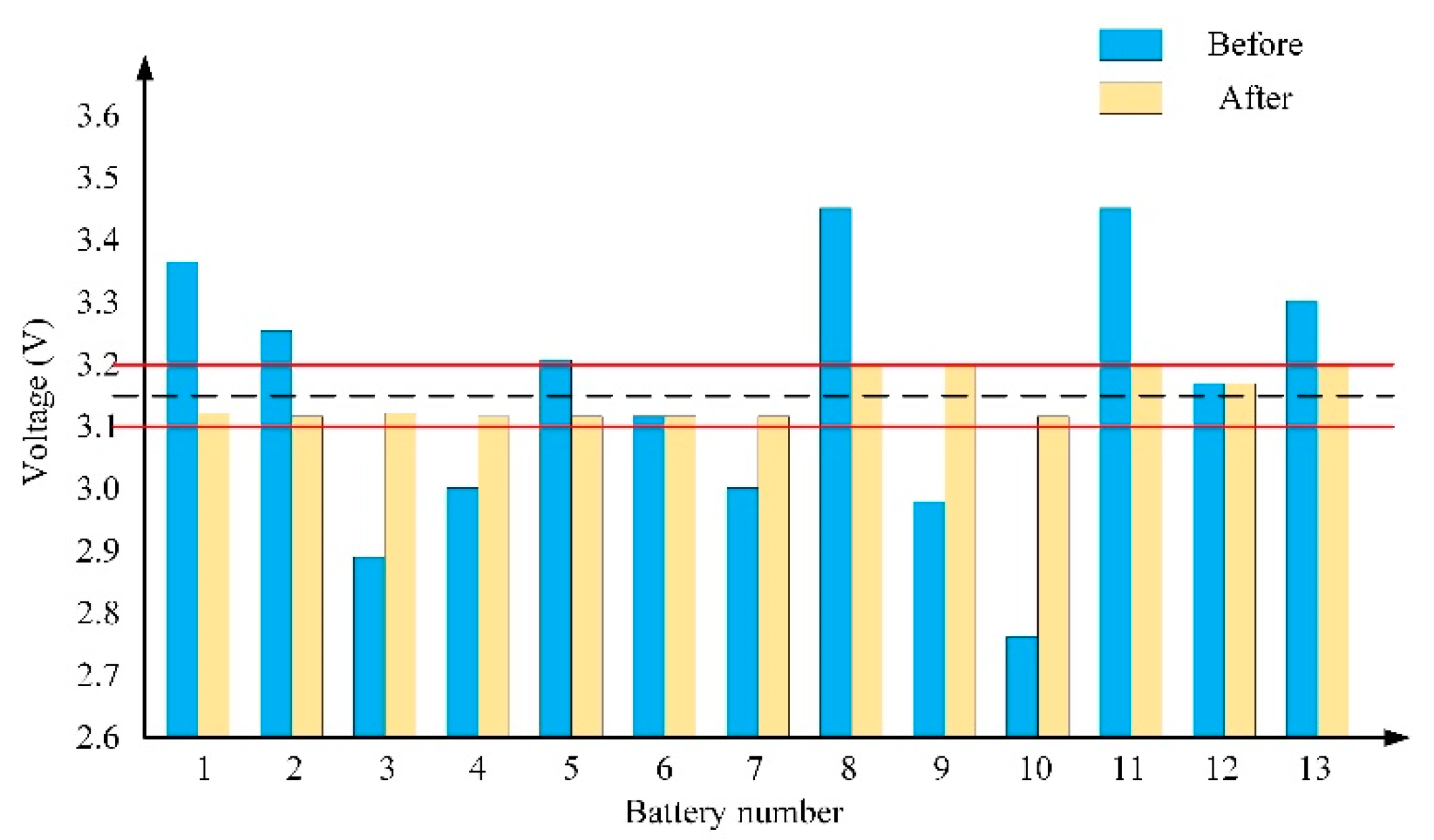
Figure 7 is the battery samples, where the blue bar represents the voltage of each cell, the black dashed line represents the average voltage of the 13 batteries, and the two red solid lines represent the upper and lower limits of the battery voltage. There is no need to start the equalization for the cells within the solid red line range. It can be seen that the average voltage of 13 series battery pack is 3.15 V, and the voltages of seven batteries are higher than the upper limit which are called rich-energy cells. The voltages of five batteries are lower than the lower limit which are called loss-energy cells. The maximum voltage difference between the cells before equalization is 0.72 V which is greater than 0.1 V, and it is necessary to start equalization.
If a simple equalization strategy is adopted, that is, the energy transferred between the cell with highest voltage and that with the lowest voltage. The voltages of the battery samples before and after equalization are shown in Figure 8. It can be seen that the maximum voltage difference between the cells after equalization is within 0.1 V, and the loss equivalent of the entire balancing process is 0.3941. The balancing time is about 42,400 s.
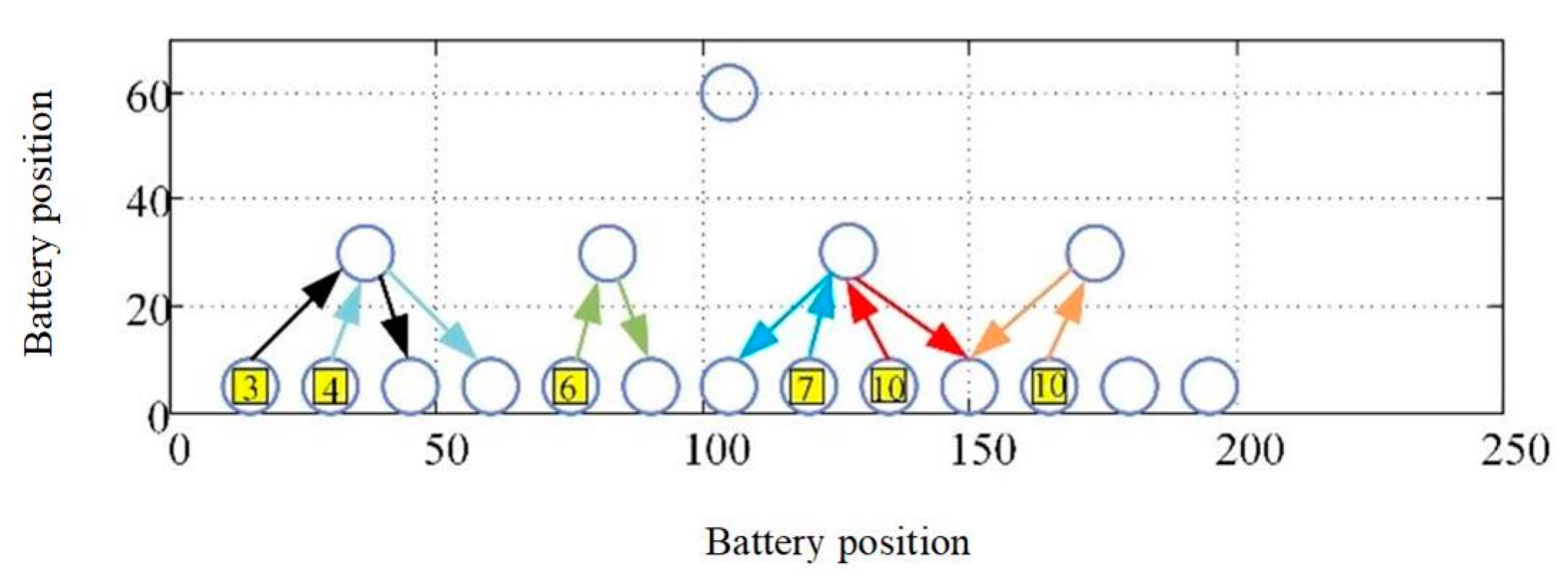
Then, we do the simulations for the best efficiency of the balancing system, that is, the least energy loss during the balancing process. The optimal balancing path planning scheme is shown in Figure 9, in which the horizontal and vertical coordinates represent the position coordinates of the batteries, and the blue hollow circles represent the battery cells. The batteries are numbered from left to right, 1 to 13, respectively. The yellow numbers in the hollow circles indicate the target cell. For instance, the number 1 battery position has a yellow number 3, which indicates that the number 1 battery discharge to number 3 battery through the transition node, and others are the same. It can be seen that in the best efficiency strategy, all the balancing paths are within the bottom equalizer. In this way, the energy transmission is direct, the number of energy conversion times is small, the energy consumption of the balancing process is little, and therefore the balancing efficiency is high. The battery voltages before and after equalization are shown in Figure 10. After equalization, the maximum voltage difference between the batteries is within 0.1 V, satisfying the constraint conditions. The simulation results show that the loss equivalent of the whole balancing process is 0.2305 after the optimization and the balancing time is 20,100 s.
For the optimal speed balancing scheme, the structure of the balancing system is the same as shown in Figure 4. Take n = 4 and m = 4 for example, and the battery samples are not changed as shown in Figure 7. Figure 11 shows the balancing path planning scheme with the best balancing speed, that is, the shortest balancing time strategy. The horizontal and vertical coordinates represent the position coordinates of the batteries and the blue hollow circles indicate the battery cells. The batteries are numbered from left to right, 1 to 13, respectively. The yellow numbers in the hollow circles indicate the target cell. For instance, the number 1 battery position has a yellow number 3, which indicates that the number 1 battery discharge to number 3 battery through the transition node, and others are the same. In the shortest time strategy, it can be seen from the optimal path planning scheme that most of the planned paths are concentrated in the bottom equalizer and only one balancing path passes through the top layer. The battery voltages before and after equalization are shown in Figure 12. The maximum voltage difference between the batteries is within 0.1 V. The simulation results show that the loss equivalent of the whole balancing process is 0.2975 after the optimization and the balancing time is 16,400 s.
To compare the balancing results with simple strategy and ant optimization algorithms clearly, the results are shown in Table 3.

6. Conclusions

This paper focuses on the study of balancing path planning strategies for long-series connected battery packs under complex imbalanced conditions. Based on the influence of the equalizer-based graph model and the parameters of the specific implementation circuit, an optimal model for the balancing efficiency and the balancing speed of the two-layer balancing system is established, respectively. The corresponding constraints are established, and the ant colony algorithm is given. Finally, the optimal models are applied to 13 series connected battery packs. The simulation results show that, compared with the series connected battery packs using a simple strategy, the balancing path planning method proposed in this paper can deal well with the complex imbalanced conditions of long-series battery packs. In this way, the balancing path can be shortened and the number of energy conversions can be reduced. Both the balancing speed and the efficiency have great advantages.

Author Contributions

Y.C. is in charge of topology analysis and algorithm optimization; L.C. is responsible for algorithm simulation; T.S. takes charge of results analysis; S.Y. and R.Y. are responsible for data collection and X.L. is in charge of writing. All authors have read and agreed to the published version of the manuscript.

Funding

This research work was supported by the National Natural Science Foundation of China (52005116, 11832009, 51677042), the Natural Science Foundation of Guangdong Province (2020A1515011247) and Department of Education of Guangdong Province Innovative and Strong School Project (Natural Science) (2020KQNCX054).

Conflicts of Interest

The authors declare no conflict of interest.

References

  1. Kim, H.-S.; Park, K.-B.; Park, S.-H.; Moon, G.-W.; Youn, M.-J. A new two-switch flyback battery equalizer with low voltage stress on the switches. In Proceedings of the 2009 IEEE Energy Conversion Congress and Exposition, Jose, CA, USA, 20–24 September 2009; pp. 511–516. [Google Scholar]
  2. Shang, Y.; Cui, N.; Zhang, C. An Optimized Any-Cell-to-Any-Cell Equalizer Based on Coupled Half-Bridge Converters for Series-Connected Battery Strings. IEEE Trans. Power Electron. 2019, 34, 8831–8841. [Google Scholar] [CrossRef]
  3. Shang, Y.; Cui, N.; Duan, B.; Zhang, C. Analysis and Optimization of Star-Structured Switched-Capacitor Equalizers for Series-Connected Battery Strings. IEEE Trans. Power Electron. 2017, 33, 9631–9646. [Google Scholar] [CrossRef]
  4. Li, S.; Mi, C.C.; Zhang, M. A high efficiency low cost direct battery balancing circuit using a multi-winding transformer with reduced switch count. In Proceedings of the 2012 Twenty-Seventh Annual IEEE Applied Power Electronics Conference and Exposition (APEC), Orlando, FL, USA, 5–9 February 2012; pp. 2128–2133. [Google Scholar]
  5. Baronti, F.; Roncella, R.; Saletti, R. Performance comparison of active balancing techniques for lithium-ion batteries. J. Power Sources 2014, 267, 603–609. [Google Scholar] [CrossRef] [Green Version]
  6. Du, W.; Huang, X.; Yang, S.; Zhang, F.; Wu, X.; Qian, Z. A novel equalization method with defective-battery- Modularization. IEEE Trans. Veh. Technol. 2009, 58, 3216–3223. [Google Scholar]
  7. Shang, Y.; Zhang, C.; Cui, N.; Mi, C.C. A Delta-Structured Switched-Capacitor Equalizer for Series-Connected Battery Strings. IEEE Trans. Power Electron. 2019, 34, 452–461. [Google Scholar]
  8. Park, H.-S.; Kim, C.H.; Park, K.-B.; Moon, G.-W.; Lee, J.-H. Design of a Charge Equalizer Based on Battery replacing for series-connected lithium battery strings. In Proceedings of the First IEEE Energy Conversion Congress and Exposition (ECCE2009), San Jose, CA, USA, 20–24 September 2009; pp. 1806–1811. [Google Scholar]
  9. Moody, M. A high reliability battery management system. J. Power Sources 1986, 18, 223–231. [Google Scholar] [CrossRef] [Green Version]
  10. Daowd, M.; Omar, N.; Bossche, P.V.D.; Van Mierlo, J. Passive and active battery balancing comparison based on MATLAB simulation. In Proceedings of the 2011 IEEE Vehicle Power and Propulsion Conference, Chicago, IL, USA, 6–9 September 2011; pp. 1–7. [Google Scholar]
  11. Gallardo-Lozano, J.; Romero-Cadaval, E.; Milanes-Montero, M.I.; Guerrero-Martinez, M.A. Battery equalization active methods. J. Power Sources 2014, 246, 934–949. [Google Scholar] [CrossRef]
  12. Hsieh, Y.; Moo, C.; Tsai, I.; Cheng, J. Dynamic charge equalization for series-connected batteries. In Proceedings of the 2002 IEEE International Conference on Industrial Technology, Bankok, Thailan, 11–14 December 2003; Volume 150, pp. 501–505. [Google Scholar]
  13. Zhang, W.; Gong, X.; Han, G.; Zhao, Y. An Improved Ant Colony Algorithm for Path Planning in One Scenic Area with Many Spots. IEEE Access 2017, 5, 13260–13269. [Google Scholar] [CrossRef]
  14. Shang, Y.; Xia, B.; Yang, J.; Zhang, C.; Cui, N.; Mi, C.C. A delta-structured switched-capacitor equalizer for series-connected battery strings. In Proceedings of the 2017 IEEE Energy Conversion Congress and Exposition (ECCE), Cincinnati, OH, USA, 1–5 October 2017; pp. 4493–4496. [Google Scholar]
  15. Dorigo, M.; Maniezzo, V.; Colorni, A. Ant system: Optimization by a colony of cooperating agents. IEEE Trans. Syst. Mancybern. Part B 1996, 26, 29–41. [Google Scholar] [CrossRef] [Green Version]
  16. Wang, X.; Choi, T.M.; Liu, H.; Yue, X. A novel hybrid ant colony optimization algorithm for emergency transportation problemsduring post disaster scenarios. IEEE Trans. Syst. Man Cybern. Syst. 2018, 48, 545–556. [Google Scholar] [CrossRef]
  17. Zhou, Y.; Zhang, J.; Wang, Y. Performance Analysis of the (1+1) Evolutionary Algorithm for the Multiprocessor Scheduling Problem. Algorithmica 2014, 73, 21–41. [Google Scholar] [CrossRef]
  18. Yu, Y.; Yao, X.; Zhou, Z.-H. On the approximation ability of evolutionary optimization with application to minimum set cover. Artif. Intell. 2012, 180–181, 20–33. [Google Scholar] [CrossRef] [Green Version]
  19. Farhanchi, M.; Hassanzadeh, R.; Mahdavi, I.; Mahdavi-Amiri, N. A modified ant colony system for finding the expected shortest path in networks with variable arc lengths and probabilistic nodes. Appl. Soft Comput. 2014, 21, 491–500. [Google Scholar] [CrossRef]
  20. Sudholt, D.; Thyssen, C. Running time analysis of Ant Colony Optimization for shortest path problems. J. Discret. Algorithms 2012, 10, 165–180. [Google Scholar] [CrossRef] [Green Version]
  21. Calle, J.; Rivero, J.; Cuadra, D.; Isasi, P. Extending ACO for fast path search in huge graphs and social networks. Expert Syst. Appl. 2017, 86, 292–306. [Google Scholar] [CrossRef]
  22. Cheng, L.; Liu, G.; Huang, H.; Wang, X.; Chen, Y.; Zhang, J.; Meng, A.; Yang, R.; Yu, T. Equilibrium analysis of general N-population multi-strategy games for generation-side long-term bidding: An evolutionary game perspective. J. Clean. Prod. 2020, 276, 124123. [Google Scholar] [CrossRef]
  23. Niu, Y.; Wang, S.; He, J.; Xiao, J. A novel membrane algorithm for capacitated vehicle routing problem. Soft Comput. 2014, 19, 471–482. [Google Scholar] [CrossRef]
  24. De Grancy, G.S.; Reimann, M. Vehicle routing problems with time windows and multiple service workers: A systematic comparison between ACO and GRASP. J. Oper. Res. 2014, 24, 29–48. [Google Scholar]
  25. Chen, Y.; Liu, X.; Cui, Y.; Zou, J.; Yang, S. A Multi-winding Transformer Cell-to-Cell Active Equalization Method for Lithium-Ion Batteries with Reduced Number of Driving Circuits. IEEE Trans. Power Electron. 2016, 37, 4916–4929. [Google Scholar] [CrossRef]
  26. Chen, Y.; Liu, X.; Fathy, H.K.; Zou, J.; Yang, S. A graph-theoretic framework for analyzing the speeds and efficiencies of battery pack equalization circuits. Int. J. Electr. Power Energy Syst. 2018, 98, 85–99. [Google Scholar] [CrossRef]
  27. Liu, J.; Chen, Y.; Fathy, H.K. Nonlinear Model-Predictive Optimal Control of an Active Cell-to-Cell Lithium-Ion Battery Pack Balancing Circuit. IFAC-PapersOnLine 2017, 50, 14483–14488. [Google Scholar] [CrossRef]
  28. Zhuo, X.; Gao, Y. Network coding resources optimization of coding-link cost based on the modified ant colony algorithm. In Proceedings of the 2017 3rd IEEE International Conference on Computer and Communications, Chengdu, China, 13–16 December 2017; pp. 536–540. [Google Scholar]
  29. Li, Y.; Zhang, C.; Yang, Q.; Li, J.; Zhang, Y.; Zhang, X.; Xue, M. Improved ant colony algorithm for adaptive frequency-tracking control in WPT system. IET Microw. Antennas Propag. 2017, 12, 23–28. [Google Scholar] [CrossRef]
  30. Liu, Z.; Liu, X.; Han, J.; Yang, W. An optimization algorithm for equalization scheme of series-connected energy storage cells. In Proceedings of the IEEE Transportation Electrification Conference and Expo, Asia-Pacific, Harbin, China, 7–10 August 2017; pp. 1–6. [Google Scholar]
  31. Jiao, Z.; Ma, K.; Rong, Y.; Wang, P.; Zhang, H.; Wang, S. A path planning method using adaptive polymorphic ant colony algorithm for smart wheelchairs. J. Comput. Sci. 2018, 25, 50–57. [Google Scholar] [CrossRef]
  32. Rathee, M.; Kumar, S.; Gandomi, A.H.; Dilip, K.; Balusamy, B.; Patan, R. Ant Colony Optimization Based Quality of Service Aware Energy Balancing Secure Routing Algorithm for Wireless Sensor Networks. IEEE Trans. Eng. Manag. 2019, 1–13. [Google Scholar] [CrossRef]
  33. Dai, S.; Wang, J.; Shan, Z.; Wei, Y. Analysis, Design and Implementation of Flexible Interlaced Converter for Lithium Battery Active Balancing in Electric Vehicles. J. Power Electron. 2019, 19, 858–868. [Google Scholar]
  34. Dong, W.; Li, Y.; Xiang, J. Optimal Sizing of a Stand-Alone Hybrid Power System Based on Battery/Hydrogen with an Improved Ant Colony Optimization. Energies 2016, 9, 785. [Google Scholar] [CrossRef]
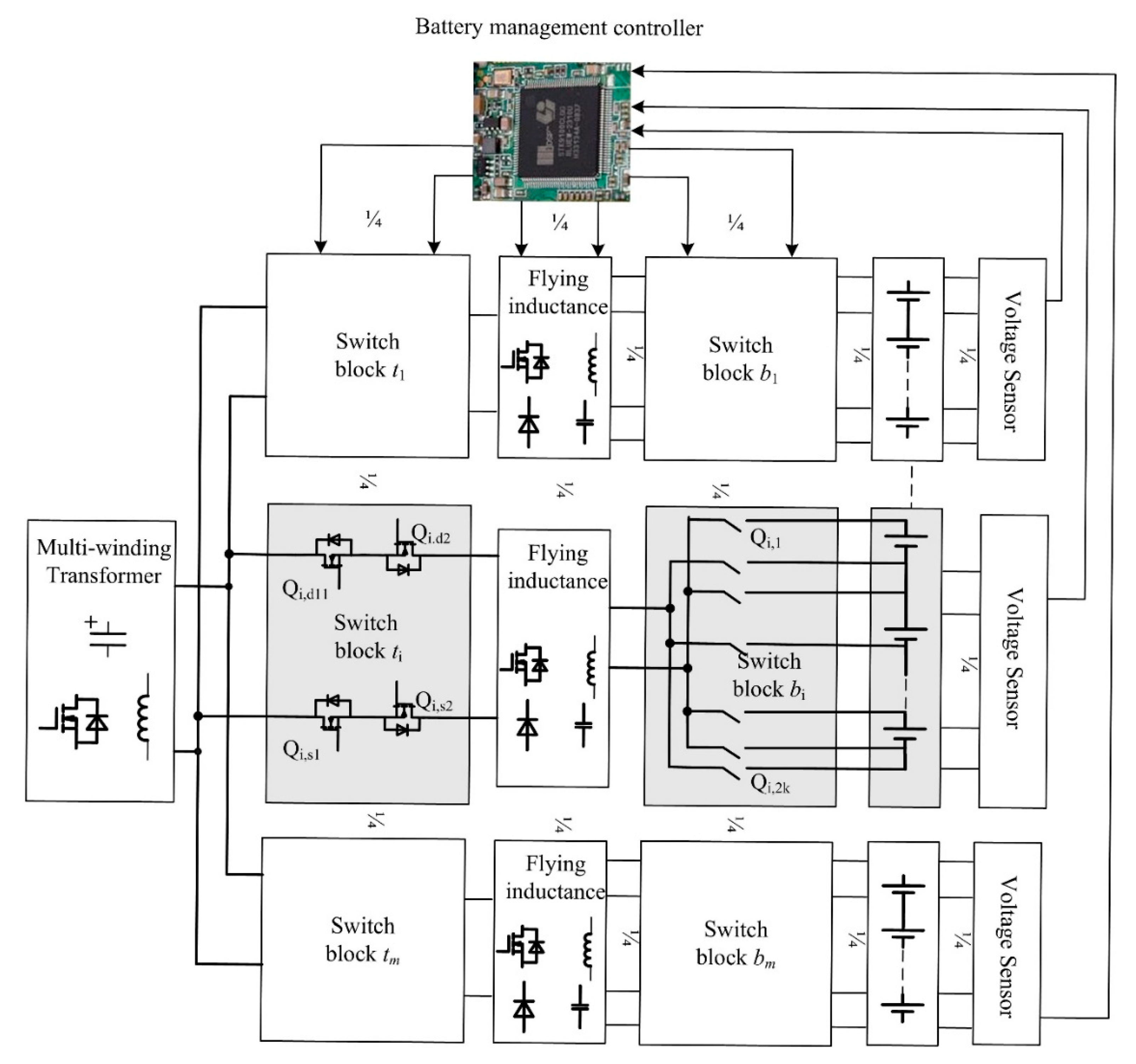
Figure 1. Block diagram of two-layer balancing system.
Electronics 09 01816 g001
Figure 2. The bottom equalizer structure.
Electronics 09 01816 g002
Figure 3. The top equalizer structure.
Electronics 09 01816 g003
Figure 4. The Graph Model of the two-layer balancing system.
Electronics 09 01816 g004
Figure 5. Action rules for battery balancing system.
Electronics 09 01816 g005
Figure 6. The flowing chart of the adopted algorithm.
Electronics 09 01816 g006
Figure 7. Voltages of 13 series connected batteries.
Electronics 09 01816 g007
Figure 8. Voltages of batteries for simple control strategy.
Electronics 09 01816 g008
Figure 9. Balancing paths for best balancing efficiency.
Electronics 09 01816 g009
Figure 10. Voltages of batteries for best balancing efficiency.
Electronics 09 01816 g010
Figure 11. Balancing paths for best balancing speed.
Electronics 09 01816 g011
Figure 12. Voltages of batteries for best balancing speed.
Electronics 09 01816 g012
Table 1. The graph model of elements in the equalizer.
Elements in the Balancing SystemGraph Elements
Capacitor or inductanceIntermediate Node
Battery cellTarget Node
Energy transferred pathDirected edge
Table 2. Specific implementation process of the balancing algorithm.
StepsItems
1Define of digraph matrices
2Define of nodes and edges
3Detect the imbalanced statusIf yes, obtain the Demand matrix D, Edge state matrix Ys and Unit priority matrix Lp, and then calculate the optimal solution according to Equations (6) and (7)
Else, go back to step 3
4Output matrices related to edges
5Update the Edge status matrix Ys
Table 3. The balancing results of different strategies.
ItemsSimple StrategyBest Balancing EfficiencyBest Balancing Speed
Maximum voltage difference0.1 V<0.1 V<0.1 V
Equivalent loss0.39410.23050.2975
Energy transferred path42,400 s20,100 s16,400 s
Publisher’s Note: MDPI stays neutral with regard to jurisdictional claims in published maps and institutional affiliations.