Article

A Multiplicatively Weighted Voronoi-Based Workspace Partition for Heterogeneous Seeding Robots

Department of Rural and Biosystems Engineering, Chonnam National University, Gwangju 61186, Korea
*
Author to whom correspondence should be addressed.
Electronics 2020, 9(11), 1813; https://doi.org/10.3390/electronics9111813
Submission received: 26 September 2020 / Revised: 22 October 2020 / Accepted: 30 October 2020 / Published: 2 November 2020
(This article belongs to the Special Issue Modeling, Control, and Applications of Field Robotics)

Abstract

:
Multi-robot systems (MRSs) are currently being used to perform agricultural tasks. In this regard, the deployment of heterogeneous MRSs will be essential for achieving more efficient and innovative farming in the future. In this paper, we propose a multiplicatively weighted (MW) Voronoi-based task-allocation scheme for heterogeneous agricultural robots. The seed points for area partitioning using a Voronoi diagram are obtained by performing node clustering using a k-means clustering algorithm. Heterogeneous robots have different specifications for performing various tasks. Thus, the proposed MW Voronoi-based area partitioning for heterogeneous robots is applied by considering various weighting factors. The path for each robot is computed such that the robot follows the nodes, and the computed paths serve as inputs for the workload distribution strategy that assigns paths to the robots. Simulations and field experiments were conducted to verify the effectiveness of the proposed approach.

1. Introduction

Seeding is a fundamental component of agriculture, and substantial labor is required to seed wide areas. To effectively carry out the seeding process in large fields, seeding machines have been developed and distributed to farming households [1,2,3]. However, human-driven seeding machines are exceedingly large and heavy, with an elevated center of mass that is prone to instability; in addition, they are difficult to maneuver in several types of agricultural fields. Therefore, such heavy seeding robots must be replaced with more intelligent and lightweight robots. In addition, applying seeding using only one seeding machine in a large field is highly expensive and time consuming. To overcome this, a multi-robot system can be applied to improve the seeding process through cooperation among the robots.
As the number of agricultural workers across the world continues to decrease, the use of multi-robot systems (MRSs) for conducting agricultural tasks is becoming more prevalent in large-scale farms [4,5,6]. Dividing work among robots in an MRS will improve the productivity of farming households and the yield per unit area. Agricultural MRSs have provided productivity gains, but to achieve more innovative farming in the future, heterogeneous MRSs must be introduced for agricultural use [7].
Heterogeneous agricultural field robots are gaining significant attention with regard to their use for efficiently accomplishing a variety of agricultural tasks [8,9]. In [10], systems were developed to determine the optimal paths for allowing heterogeneous vehicles to conduct agricultural tasks. The paths were determined based on variables including the number of vehicles, speed, turning radii, field geometry, tank capacity, and fuel consumption. The problem was expressed mathematically as a combinatorial optimization problem, in which the optimal order was used to cover the tracks of the field and the optimal transitions for refilling were found. In a previous study [11], the application of heterogeneous robots to monitor the environmental variables of a greenhouse was studied. This multi-heterogeneous-robot system involves the use of both ground and aerial vehicles to provide flexibility and improve the performance. In [12], heterogeneous robots were used to perform spraying tasks based on the cooperation of at least two mobile robots that moved from either side of a vine row. These robots applied this task in the form of followers following a lead robot.
To utilize MRSs for conducting agricultural tasks, a multi-robot task allocation (MRTA) must be applied to allocate tasks to the robots. MRTA is one of the most challenging problems presented by an MRS; a set of tasks must be assigned to a set of robots in a manner that optimizes the overall system performance, subject to a set of constraints [13]. This problem varies over time with events such as environmental changes; therefore, task allocation is dynamic and must be applied iteratively [14]. There are many more considerations, particularly in the case of a heterogeneous MRTA, given that robots incur different costs depending on their model [15].
MRTA problems can be taxonomized along three axes [16], and such a taxonomy can help organize MRTA problems and identify theoretical foundations [17].
  • Single-task (ST) robots versus multi-task (MT) robots.
  • Single-robot (SR) tasks versus multi-robot (MR) tasks.
  • Instantaneous assignment (IA) versus time-extended assignment (TA).
The first axis distinguishes between problems in which each robot is capable of performing only one task at once and problems in which the robot can perform more than one task simultaneously. This means that a robot can perform different tasks in sequence. For example, some robots can sense the environment using a camera at the same time that they apply the seeding. In the second axis, the single-robot (SR) system can be expressed as exhibiting a weak cooperation [18], which indicates that the completion of each task requires exactly one robot. In this case, the robots do not know the states of the other robots and only perform their own tasks as assigned by the central control system. The multi-robot (MR) system can be expressed as one with strong cooperation [19,20,21], indicating that some tasks can require multiple robots. These tasks include carrying a large item that a single robot cannot handle on its own. In this case, the robots communicate with each other to exchange their locations and statuses. In the third axis, “instantaneous assignment (IA)” indicates that the instantaneous allocation of the tasks to the robots is performed without planning for future allocations. In this case, the robots are unaware of the states of the other robots and only accomplish their own tasks, which are assigned by the central control system. Here, “time-extended assignment (TA)” indicates that each robot is allocated several tasks that must be executed according to a given plan. In this case, the robots should maintain connectivity with each other and remain aware of their mutual locations and statuses.
In this study, a single-task (ST)–SR-=IA-type MRTA system was developed. Considering the seeding process, it is not necessary for several robots to collaboratively apply the seeding. Therefore, there is no need for communication between robots, and each robot only needs to receive commands from the central control system pertaining to its own driving path for achieving the seeding. Our approach for MRTA involves partitioning the workspaces according to the number of robots, signing each sub-area to a robot, and controlling the robot to allow it to conduct the seeding in its allocated zone. A workspace partition is applied using a Voronoi diagram [22,23]. Voronoi diagrams are typically used to allocate multi-robot paths or workspaces, and a variety of recent studies have been conducted on this topic [24,25,26].
In a recent study [27], we developed a task allocation system based on a Voronoi diagram for a multi-robot spray system in an orchard. However, there is a limitation in that the area partitioning of a multi-robot is not optimized or balanced. To partition the workspace for heterogeneous robots, not only the location, but also various mechanical specifications should be considered. To improve the feasibility and practicality of the developed task allocation system for heterogeneous robots, this study used a multiplicatively weighted (MW) Voronoi diagram to delineate the workspace by assigning different weights to different types of robots. Thus, an MW Voronoi diagram was used to allocate workspaces equally to a multi-robot system [28].
In this study, task allocation for heterogeneous agricultural robots conducting a seeding task is considered. The focus of this approach is to apply a task allocation and coordination using various factors according to the specifications of the robots. As the objective function of the MRTA system, we have suggested that a multi-robot efficiently assigns a workspace for the seeding tasks. The efficiency means that each robot has similar working hours.
The main contributions of this study are as follows:
  • An MW Voronoi-based approach for workspace partitioning for a heterogeneous MRS was applied to conduct seeding tasks.
  • The heterogeneous MRTA applied in this study was optimized by considering various weighting factors associated with the heterogeneous robots.
  • An experiment and evaluation were used to demonstrate the applicability of our approach.
The remainder of this paper is organized as follows: In Section 2, seeding robot modeling and a control algorithm comprising obstacle avoidance control and path-following control systems are introduced. In Section 3, the heterogeneous MRTA for the seeding task is described. In Section 4 and Section 5, our implementation of this robotic system and related experiments are presented. Finally, Section 6 concludes this paper with a summary of our contributions and a brief discussion of future research.

2. Seeding Robot Control

2.1. Kinematic and Dynamic Modeling

The kinematic and dynamic equations for unmanned ground vehicles (UGVs) (i.e., seeding robots) are described as follows. We consider n UGVs with defined positions when the coordinate frame is { U } and the body frame is { D } . The kinematic and dynamic equations of the UGV are as follows:
x i ˙ = ν i cos ( ψ i ) y i ˙ = ν i sin ( ψ i ) ψ i ˙ = ω i
D ( x i ) ν i ˙ ω i ˙ + Q ( x i , w i ) ν i ψ i ˙ = μ i + ϱ i ,
where x i and y i are the coordinates of the UGV with respect to the coordinate frame { U } , and ν i and ω i are the linear and angular speeds, respectively, of the ith robot expressed in { D } , where ψ i denotes the heading angle. Furthermore, μ i = [ μ i ν , μ i ω ] T and ϱ i = [ ϱ i ν , ϱ i ω ] T are the control input and the external force and torque, respectively. In addition, D ( x i ) 3 is the positive-definite symmetric inertia matrix, and Q ( x i , ω i ) 3 × 3 is the Coriolis matrix.

2.2. Distributed Control

We define the following distributed UGV control system for the low-level control of heterogeneous field robots. The heterogeneous field robots consist of a group of n UGVs, and we denote R i 3 as the position of the ith robot, i = 1 , , n . Here, we define the virtual point (VP) λ i : t b i ( t ) 3 as follows: R i .
We define the dynamic undirected connectivity graph C : = { V , E } by the vertex set V : = { 1 , 2 , , n } , representing the heterogeneous robots, and the edge set E : = { e i j : i = 1 , 2 , , n , j n i } , representing the connectivity among heterogeneous robots. The dynamic neighbor set Y i of the i robot is defined as follows:
S i : = { j V : i receives information from j , i j } .
Consequently, the kinematic evolution of the VP λ i generated by a distributed UGV control scheme for the ith robot is as follows:
λ i ˙ ( t ) : = u i o + u i u , λ i ( 0 ) = R i ( 0 ) ,
where the two control inputs u i o 3 and u i u 3 represent the velocity terms.

2.2.1. Obstacle Avoidance

The value of u i o 3 is expressed through the following equation as a control input based on a potential field that allows heterogeneous robots to avoid obstacles through a certain distance threshold Λ o + :
u i o : = j O i Φ i j o ( λ i λ j o ) T λ i .
Here, O i denotes the set of obstacles of the ith VP with an obstacle point λ j o that corresponds to the position of the rth obstacle in the environment. In addition, Φ i j o denotes a specific artificial potential function that produces a repulsive behavior if λ i λ j o < Λ o and a null behavior if λ i λ r j Λ o . When the distance between the VP and the obstacles approaches Λ o , the repulsive behavior infinitely increases. However, if λ i λ j o Λ o , Φ i j o gradually converges to zero.

2.2.2. Path Following

Here, u i u 3 represents the desired velocity input of the VP that is controlled by the planning algorithm, which is defined as follows:
u i u = K P ( t ) e i ( t ) + K I e i ( t ) d t + K D d d t e i ( t ) ,
where T i 3 denotes the target velocity, and e i ( t ) = T i λ i ˙ indicates the velocity error between the target trajectory and the VP. A traditional proportional-integral-derivative (PID) controller widely used to solve nonlinear control problems was used for path following [29,30]. In addition, K P , K I , and K D are the parameters of the desired velocity controller.

3. Task Allocation

In this section, we present a method for allocating tasks to heterogeneous seeding robots. Our MRTA system involves five steps:
  • Creating a node for the seeding task from the agricultural field;
  • Node clustering using a k-means algorithm;
  • MW Voronoi-based area partitioning;
  • Path planning;
  • Seeding.
The agricultural field is designated as the “workspace.” The positions of the nodes are designated with respect to the agricultural field. The nodes are clustered using the k-means clustering algorithm, and each workspace is partitioned into sub-areas based on the MW Voronoi diagram. Path planning for the agricultural task is then executed for each sub-area. Finally, each path plan is sent to the robots to be implemented. A robot follows an assigned path, whereas a real-time kinematic (RTK) global navigation satellite system (GNSS) is used for localization. Figure 1 shows the global MRTA system flowchart.
Our MRTA system is only applicable when the workspace is two-dimensional. Robots are treated as points in the workspace, but kinematic and dynamic constraints can be considered. To conduct the task, the robot needs information regarding its location in the workspace. Location information of the robot must continue to be sent to the central supervisor, which is why the connection of the network between the robot and central supervisor is essential. Therefore, every robot must be equipped with a high-accuracy positioning system (RTK-GNSS) to inform about its location, as well as a communication system with a long communication distance to cover all wide areas.

3.1. Node Creation

Node creation is the prior step necessary for finding the center node for Voronoi-based area partitioning. The nodes are used to indicate spots where the seeds are to be planted. The robot must pass over the nodes corresponding to the assigned area and apply the seeding on the nodes. Thus, the nodes form the basis for the path that the robot must follow during the execution of the planned path. Therefore, it is crucial to specify the ( x , y ) coordinates for these nodes.
The nodes are placed at a specific distance (from one another) in the agricultural field (Figure 2). To create the nodes, aerial images of the agricultural field are obtained using unmanned aerial vehicles. After the aerial images are obtained, the specific distance (density and pattern) of each node is chosen. Determining the proper planting pattern and spacing is vital for increasing the yield and decreasing the interference from the weeds [31]. A specified planting pattern for a specific crop may provide an optimal space to maximize the vegetative regions, which may subsequently receive a high amount of solar energy and result in the maximum yield [32]. Therefore, the specific distance of the planting distance depends on the type of crop. The chosen row and column spacing can affect the crop growth, weed competition, grain yield, and farm profitability.

3.2. Node Clustering

To partition an area using a Voronoi diagram, a center node is required. Node clustering using the k-means clustering algorithm must first be applied to designate the center nodes. The k-means clustering algorithm is a well-known clustering method that has been studied over recent decades owing to its simplicity [33]. A k-means clustering approach involves partitioning the gathered data into n groups of data. Furthermore, the k-means clustering algorithm searches for partitions to minimize the square error between the empirical mean of the cluster and the node point of the cluster.
Consider a collection of node points P = { x i } , ( i = 1 , 2 , , m ) and a collection of points belonging to a cluster, C = { c j } , ( j = 1 , 2 , , n ). Here, μ j is the average of cluster c j . The objective of the k-means algorithm is to minimize the sum of the squared errors for all n clusters. The square error between the points inside x and μ j is determined using Equations (7) and (8).
J ( C j ) = x ϵ C j x μ j 2
J ( C ) = j = 1 n x ϵ C j x μ j 2 ,
where n is defined as the number of multiple robots required for the seeding task. The k-means clustering algorithm is a series of processes consisting of four states. First, the number of cluster heads n and each centroid are initialized. Second, all nodes are assigned to the nearest cluster head. Third, the location of the new cluster head is calculated such that the distance between the node assigned to each cluster head and the new head is minimal. Finally, states 2 and 3 are repeated until there are no changes in any of the cluster heads.

3.3. Area Partitioning

Once the cluster heads of the nodes have been defined, they are designated as the center nodes, and the workspaces are divided using a Voronoi diagram. A Voronoi diagram is a geometric structure that assumes the proximity (nearest neighbor) rule when associating each point in the 2 space to the site point that is closest to it [22]. The Voronoi diagram is an algorithm that divides the space according to the points belonging to each seed point in the plane space. The entire area is divided into n sub-areas.
Let the location of facility g i be indicated by X i = ( x i , y i ) . In addition, let p be an arbitrary location in the plane indicated by X = ( x 1 , y 2 ) . We define G = { g 1 , g 2 , , g i } as a collection of non-overlapping areas in the plane, and define d ( p , g i ) as the Euclidean distance between points p and g i , as defined in Equation (3).
d ( p , g i ) = X X i
Here, point p exists within the area g i . The ordinary Voronoi diagram area V ( g i ) is defined as follows:
V ( g i ) = p 2 d ( p , g i ) d ( p , g j ) , j i . .
To partition the workspace for a heterogeneous MRS, the various specifications of each robot should be considered. Therefore, we suggest the use of an MW Voronoi diagram to divide the workspace for different types of robots. To employ an MW Voronoi diagram for the aforementioned application, the distance between points is multiplied by the positive weights. Based on the above concept, we now add weight w i to the ordinary Voronoi diagram. The weight w i applied to the robot r i is determined as follows:
w i = σ w i l + φ w i m v + ζ w i c ,
where σ , φ , and ζ are the gain coefficients, and setting these values to zero leads to the removal of the effect of the corresponding weight.
Here, w i I represents the weight from l i , which is the distance between the initial location of the robot and the starting point of the task, which is defined as follows:
w i l = 1 ( l i i = 1 n l i )
l i = X i i l X i s t .
Here, X i l = { X 1 i l , , X n i l } denotes a set of the initial locations of the robots, and X s t = { X 1 s t , , X n s t } denotes a set of robot starting points for the tasks.
Furthermore, w i m v represents the weight derived from m v i , which is the maximum velocity of the robot, which is defined as follows:
w i m v = m v i i = 1 n m v i .
Here, w i c represents the weight derived from c i , which is the seed tank capacity as determined by the robot’s payload, which is defined as follows:
w i c = c i i = 1 n c i .
The elements of the weights l i , m v i , and c i are all constants. The units of the distance, velocity, and payload are unimportant if all units of the robots are unified. In this study, m, m/s, and kg are used. The weights are multiplied by the corresponding gain coefficients σ , φ , and ζ .
Subsequently, the functional form of the weighted distance d M W ( p , g i ) is defined as follows:
d M W ( p , g i ) = 1 w i X X i , w i > 0 .
Thus, the MW Voronoi area V M W ( g i ) and MW Voronoi diagram V M W ( G ) are defined as follows:
V M W ( g i ) = p 2 d M W ( p , g i ) d M W ( p , g j ) , j i ,
V M W ( G ) = V M W ( g 1 ) , , V M W ( g n ) .
Each of the n robots is assigned to a sub-area, and the seeding task is carried out in each area by the establishment of a path plan. In Figure 3 and Figure 4, we present the application of V M W ( g i ) .

3.4. Path Planning

3.4.1. Agricultural Routing Planning

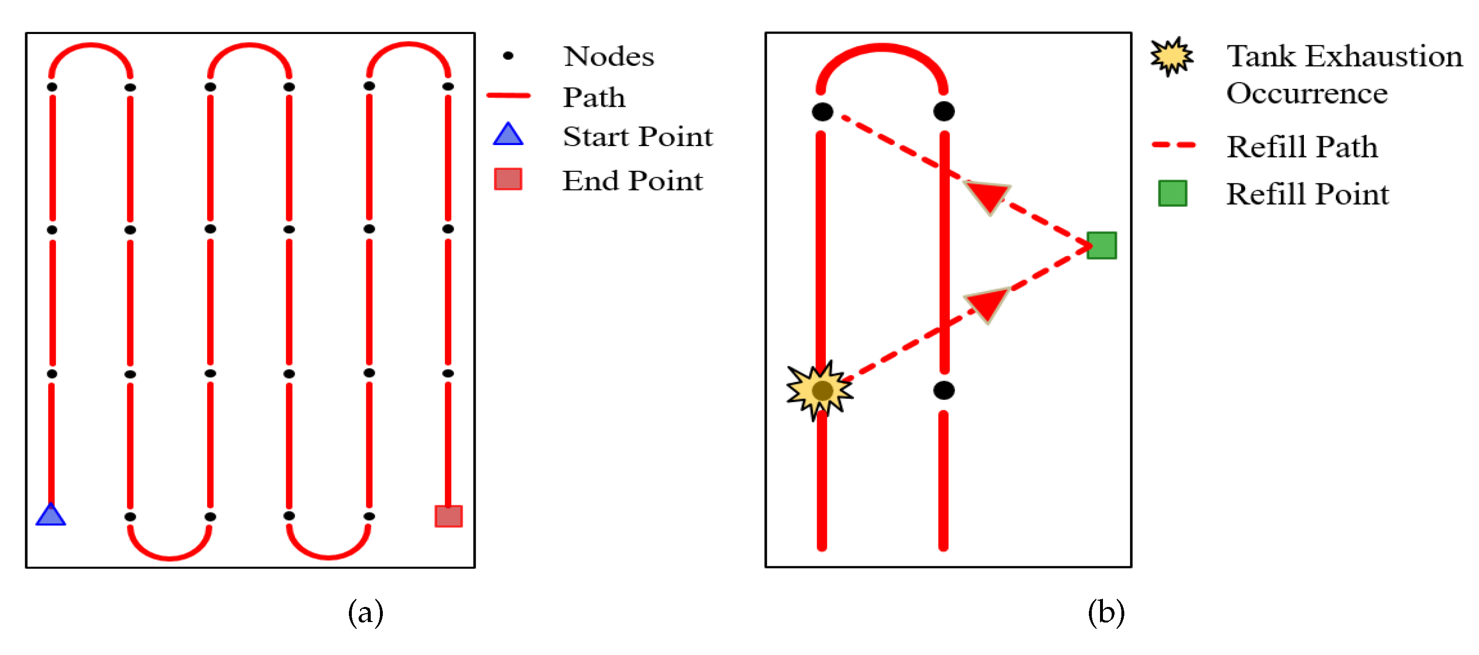
After a sub-area is assigned to the robot, path planning for the seeding task is applied within the assigned area. To plan the path, paths are computed through the previously determined node locations such that the robot follows the nodes. The computed paths serve as inputs for the workload-distribution strategy, which assigns the paths to the robots. The paths are formed in a straight line along the nodes in a row. A path is computed by connecting the endpoint node of a row and the node that serves as the starting point of the next row with a straight line (Figure 5a). The paths are also computed by considering the initial position of the robot. The path has initial and final points, and the node closest to the robot’s initial position is the initial point.
However, depending on the rotation radius of the mechanical structure of the robot, it may not be possible to drive on this path. Therefore, a method for connecting the end-point node of the line with the node that serves as the starting point of the next row differs depending on the rotation radius of the robot.

3.4.2. Refill Planning

Each robot possesses a seed tank capacity that is determined based on the payload. Accordingly, when the seeds in the seed tank are exhausted, the robot has to go to a refill point and recharge its tank with seeds. The robot moves to the refill point nearest its current location to receive seed refills, and the path used to achieve this is computed by avoiding nodes that are already seeded. When the seed refill is complete, the robot returns to the node that was last reached, and resumes the seeding task (Figure 5b).

4. Simulations

4.1. Experimental Setup

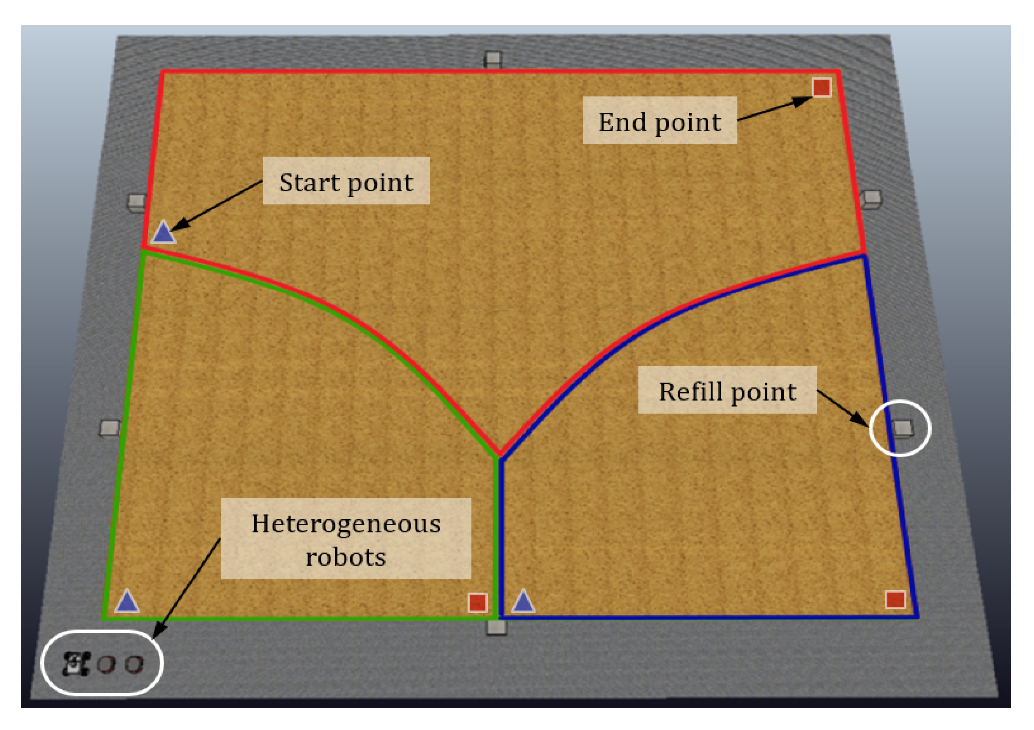
To evaluate the performance of our heterogeneous MRTA system, a simulation was conducted using a physics-based simulator for a heterogeneous seeding system comprising multiple robots, as shown in Figure 6. A Pioneer 3-AT model of Adept Inc. and Summit_XL model of Robotnik Inc. were adopted as the tasking UGVs, which have dynamic characteristics in this simulator. The workspace, as shown in Figure 6, was approximately 1225 m 2 (35 m × 35 m) in the area. Each robot drives at its maximum speed to the starting point of its corresponding path. After the robot reaches the starting point, it conducts the seeding by driving at a velocity of 0.6 m/s. The specifications of the robots and gain coefficients used in the simulations are shown in Table 1. The maximum seed tanks of the Pioneer 3-AT and SummitXL were defined with 300 and 600 seeds based on their payload. An RTK-GNSS attached to each robot sends data to the control system during the simulation. Experiments were conducted according to the number of robots, from 3 to 5. The row spacing and column spacing settings were 2 and 4. Two refill points were placed on each side, with one up and one down.

4.2. Results and Discussion

Figure 7 and Table 2 show the simulation results based on the proposed MRTA system for heterogeneous seeding robots. When the seeds in the tank are exhausted, the robot has to go to a refill point and recharge its tank. Because of that, as shown in results, we can see that refill times occurred. In Figure 7c, UGV 5 did not take time to refill the seeds because the number of seeds that could be planted by its payload was more than the number of nodes assigned to it. The results show that the task times of the robots are similar, reducing the overall task time, because the numbers of nodes assigned to each robot have different weights depending on the robot specifications, despite the differences. As shown in Table 2, the numbers of nodes in UGVs 1 and 4 differ by approximately 29.38% (114 nodes), although the difference in task time is not much different at 2.24% (4.91 s). The results confirm that the proposed MRTA method is efficient because the tasking time is not significant compared to the difference in the number of nodes. Therefore, we verified that our MRTA approach is applicable to heterogeneous seeding robots.

5. Real-World Implementation

We used two types of UGVs (two Jackal robots and one Husky robot) to implement the proposed MRTA system (Figure 8). An RTK-GNSS attached to the UGVs sent data to the controller during the experiments. The controller sent the GPS waypoint data to each robot to indicate their required paths. During the experiments, communication between the robots and controller was achieved using the ZigBee protocol. The settings for the row spacing and column spacing were 0.3 and 0.6 m. The workspace area, as shown in Figure 8, was approximately 360 m 2 (12 m × 30 m). The workspace was small, corresponding to the use of three robots, and the payloads of each robot were adequate such that robots did not need to refill the seeds (Table 3). Therefore, in the real-world experiments, the weight parameter w i c was not used because the number of nodes to be seeded was small and the payloads of each robot were sufficient; thus, the robots did not need to consider the refill time. The specifications of the robots and gain coefficients used in the experiments are shown in Table 3. Because w i c was not considered, the gain coefficient ζ was zero.
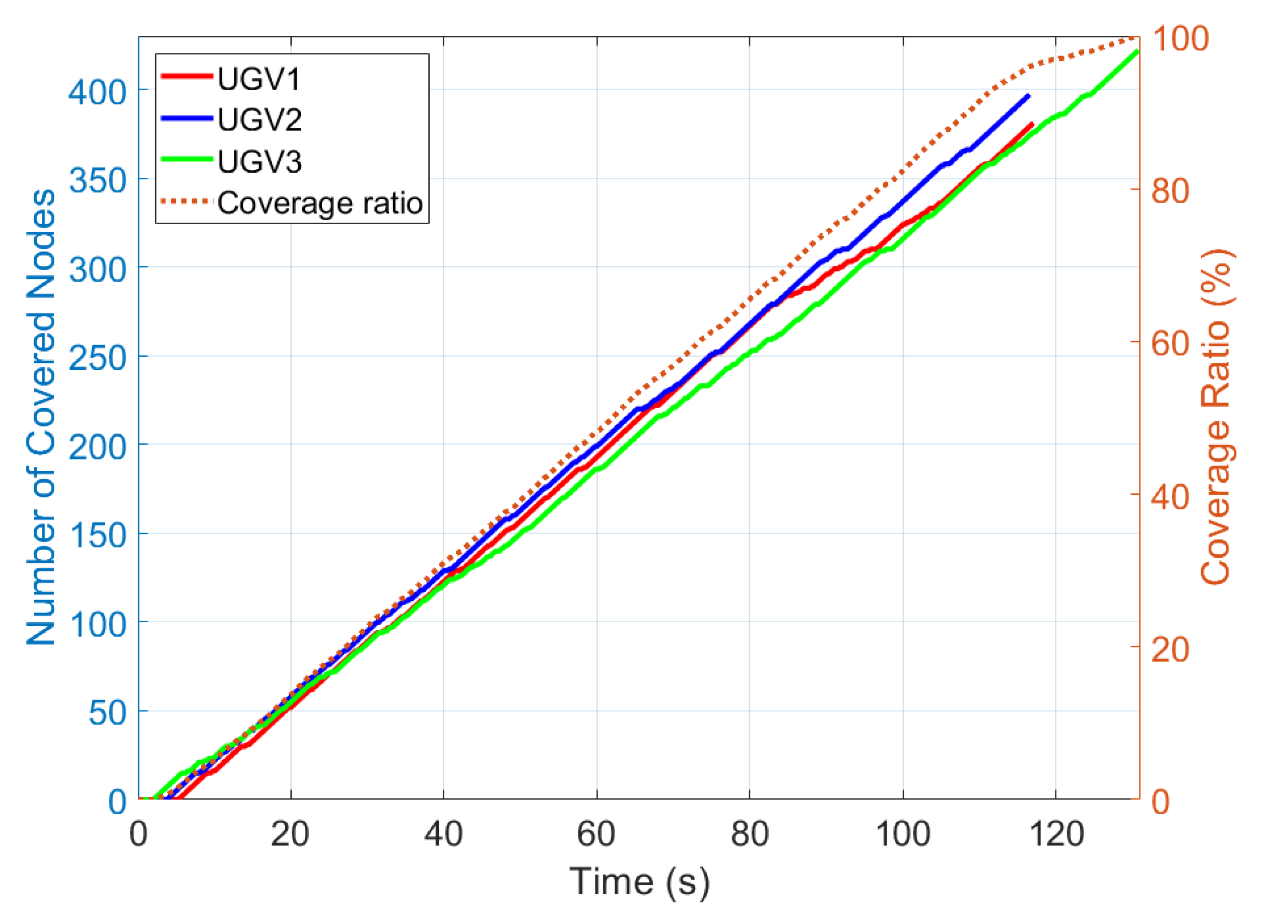
Figure 9 and Table 4 show the experiment results, which show the time required for the completion of the task and the coverage ratio. As shown in Table 4, the number of nodes in UGVs 1 and 3 differs by approximately 9.72% (41 nodes), and the task time differs by approximately 10.88% (14.23 s). The results confirmed that our MRTA system is applicable to real agricultural fields.

6. Conclusions

In this study, we developed an MW Voronoi-based workspace partitioning system for the weak cooperation of heterogeneous seeding robots. The seed points for area partitioning were obtained through node clustering using a k-means clustering algorithm. MW Voronoi-based area partitioning for heterogeneous robots was conducted using various weighting factors. The path for each robot was computed such that the robot followed the nodes, and the computed paths served as an input for the workload-distribution strategy assigning the paths to the robots. Simulations and real-world experiments were carried out to evaluate the proposed MRTA system.
There are several possible directions for future research concerning these heterogeneous robots with regard to improving the efficiency of the agricultural seeding task, including (1) optimization of the gains used for weighting, (2) connectivity maintenance for immediate responses when a robot failure event occurs, and (3) more thorough field experimentation.

Author Contributions

J.K. developed the multi-robot task allocation systems, implemented the experiments, measured and analyzed the data, and wrote the paper. C.J. developed the robot control systems. H.I.S. provided some useful suggestions, conducted the overall revision and supervision of the experiments, and writing of the paper, and conducted the project administration and funding acquisition. All authors have read and agreed to the published version of the manuscript.

Funding

This research was funded by the support of “Cooperative Research Program for Agriculture Science and Technology Development (Project No. PJ0147612020)”, Rural Development Administration, Korea.

Conflicts of Interest

The authors declare no conflict of interest.

References

  1. Sakaue, O. Development of Seeding Production Robot and Automated Transplanter System. Jpn. Agric. Res. Q. 1996, 30, 221–226. [Google Scholar]
  2. Naik, N.S.; Shete, V.V.; Danve, S.R. Precision agriculture robot for seeding function. In Proceedings of the 2016 IEEE International Conference on Inventive Computation Technologies (ICICT), Coimbatore, India, 26–27 August 2016; Volume 2, pp. 1–3. [Google Scholar]
  3. Blackmore, S.; Stout, B.; Wang, M.; Runov, B. Robotic agriculture–the future of agricultural mechanisation. In Proceedings of the 5th European Conference on Precision Agriculture, Uppsala, Sweden, 9–12 June 2005; pp. 621–628. [Google Scholar]
  4. Ju, C.; Son, H.I. Performance evaluation of multiple UAV systems for remote sensing in agriculture. In Proceedings of the Workshop on Robotic Vision and Action in Agriculture at the IEEE International Conference on Robotics and Automation (ICRA), Brisbane, Australia, 21–25 May 2018; pp. 21–26. [Google Scholar]
  5. Roldán, J.J.; del Cerro, J.; Garzón-Ramos, D.; Garcia-Aunon, P.; Garzón, M.; de León, J.; Barrientos, A. Robots in agriculture: State of art and practical experiences. In Service Robots; IntechOpen: Rijeka, Croatia, 2017. [Google Scholar]
  6. Kim, J.; Kim, S.; Ju, C.; Son, H.I. Unmanned Aerial Vehicles in Agriculture: A Review of Perspective of Platform, Control, and Applications. IEEE Access 2019, 7, 105100–105115. [Google Scholar] [CrossRef]
  7. Vu, Q.; Raković, M.; Delic, V.; Ronzhin, A. Trends in Development of UAV-UGV Cooperation Approaches in Precision Agriculture. In Proceedings of the International Conference on Interactive Collaborative Robotics, Leipzig, Germany, 18–22 September 2018; Springer: Berlin/Heidelberg, Germany, 2018; pp. 213–221. [Google Scholar]
  8. Potena, C.; Khanna, R.; Nieto, J.; Siegwart, R.; Nardi, D.; Pretto, A. AgriColMap: Aerial-Ground Collaborative 3D Mapping for Precision Farming. IEEE Robot. Autom. Lett. 2019, 4, 1085–1092. [Google Scholar] [CrossRef] [Green Version]
  9. Gonzalez-de Santos, P.; Ribeiro, A.; Fernandez-Quintanilla, C.; Lopez-Granados, F.; Brandstoetter, M.; Tomic, S.; Pedrazzi, S.; Peruzzi, A.; Pajares, G.; Kaplanis, G.; et al. Fleets of robots for environmentally-safe pest control in agriculture. Precis. Agric. 2017, 18, 574–614. [Google Scholar] [CrossRef]
  10. Conesa-Muñoz, J.; Bengochea-Guevara, J.M.; Andujar, D.; Ribeiro, A. Efficient distribution of a fleet of heterogeneous vehicles in agriculture: A practical approach to multi-path planning. In Proceedings of the 2015 IEEE International Conference on Autonomous Robot Systems and Competitions, Vila Real, Portugal, 8–10 April 2015; pp. 56–61. [Google Scholar]
  11. Roldán, J.; Garcia-Aunon, P.; Garzón, M.; de León, J.; del Cerro, J.; Barrientos, A. Heterogeneous multi-robot system for mapping environmental variables of greenhouses. Sensors 2016, 16, 1018. [Google Scholar] [CrossRef] [PubMed] [Green Version]
  12. Tourrette, T.; Deremetz, M.; Naud, O.; Lenain, R.; Laneurit, J.; De Rudnicki, V. Close coordination of mobile robots using radio beacons: A new concept aimed at smart spraying in agriculture. In Proceedings of the 2018 IEEE/RSJ International Conference on Intelligent Robots and Systems (IROS), Madrid, Spain, 1–5 October 2018; pp. 7727–7734. [Google Scholar]
  13. Khamis, A.; Hussein, A.; Elmogy, A. Multi-robot task allocation: A review of the state-of-the-art. In Cooperative Robots and Sensor Networks 2015; Springer: Berlin/Heidelberg, Germany, 2015; pp. 31–51. [Google Scholar]
  14. Gerkey, B.P.; Mataric, M.J. A framework for studying multi-robot task allocation. In Multi-Robot Systems: From Swarms to Intelligent Automata; Kluwer: Dordrecht, The Netherlands, 2003; Volume 2, pp. 15–26. [Google Scholar]
  15. Ju, C.; Son, H.I. Modeling and Control of Heterogeneous Agricultural Field Robots based on Ramadge-Wonham Theory. IEEE Robot. Autom. Lett. 2019, 1–8. [Google Scholar] [CrossRef]
  16. Gerkey, B.P.; Matarić, M.J. A formal analysis and taxonomy of task allocation in multi-robot systems. Int. J. Robot. Res. 2004, 23, 939–954. [Google Scholar] [CrossRef] [Green Version]
  17. Korsah, G.A.; Stentz, A.; Dias, M.B. A comprehensive taxonomy for multi-robot task allocation. Int. J. Robot. Res. 2013, 32, 1495–1512. [Google Scholar] [CrossRef]
  18. Ma, X.; Meng, F.; Li, Y.; Chen, W.; Xi, Y. Multi-agent-based auctions for multi-robot exploration. In Proceedings of the 2006 IEEE 6th World Congress on Intelligent Control and Automation, Dalian, China, 21–23 June 2006; Volume 2, pp. 9262–9266. [Google Scholar]
  19. Kalra, N.; Ferguson, D.; Stentz, A. Hoplites: A market-based framework for planned tight coordination in multirobot teams. In Proceedings of the 2005 IEEE International Conference on Robotics and Automation, Barcelona, Spain, 18–22 April 2005; pp. 1170–1177. [Google Scholar]
  20. Ju, C.; Son, H.I. Multiple UAV systems for agricultural applications: Control, implementation, and evaluation. Electronics 2018, 7, 162. [Google Scholar] [CrossRef] [Green Version]
  21. Ju, C.; Son, H.I. Hybrid Systems based Modeling and Control of Heterogeneous Agricultural Robots for Field Operations. In Proceedings of the 2019 ASABE Annual International Meeting. American Society of Agricultural and Biological Engineers, Boston, MA, USA, 7–10 July 2019; pp. 1–5. [Google Scholar]
  22. Aurenhammer, F. Voronoi diagrams—A survey of a fundamental geometric data structure. ACM Comput. Surv. (CSUR) 1991, 23, 345–405. [Google Scholar] [CrossRef]
  23. Brandt, J.W.; Algazi, V.R. Continuous skeleton computation by Voronoi diagram. CVGIP Image Underst. 1992, 55, 329–338. [Google Scholar] [CrossRef]
  24. Renzaglia, A.; Dibangoye, J.; Doze, V.L.; Simon, O. Multi-UAV Visual Coverage of Partially Known 3D Surfaces: Voronoi-based Initialization to Improve Local Optimizers. arXiv 2019, arXiv:1901.10272. [Google Scholar]
  25. Cortes, J.; Martinez, S.; Karatas, T.; Bullo, F. Coverage control for mobile sensing networks. IEEE Trans. Robot. Autom. 2004, 20, 243–255. [Google Scholar] [CrossRef]
  26. Breitenmoser, A.; Metzger, J.C.; Siegwart, R.; Rus, D. Distributed coverage control on surfaces in 3d space. In Proceedings of the 2010 IEEE/RSJ International Conference on Intelligent Robots and Systems, Taipei, Taiwan, 18–22 October 2010; pp. 5569–5576. [Google Scholar]
  27. Kim, J.; Son, H.I. A Voronoi Diagram-Based Workspace Partition for Weak Cooperation of Multi-Robot System in Orchard. IEEE Access 2020, 8, 20676–20686. [Google Scholar] [CrossRef]
  28. Arslan, O.; Koditschek, D.E. Voronoi-based coverage control of heterogeneous disk-shaped robots. In Proceedings of the 2016 IEEE International Conference on Robotics and Automation (ICRA), Stockholm, Sweden, 16–21 May 2016; pp. 4259–4266. [Google Scholar]
  29. Sun, Y.L.; Er, M.J. Hybrid fuzzy control of robotics systems. IEEE Trans. Fuzzy Syst. 2004, 12, 755–765. [Google Scholar] [CrossRef]
  30. Braune, S.; Liu, S.; Mercorelli, P. Design and control of an electromagnetic valve actuator. In Proceedings of the 2006 IEEE Conference on Computer Aided Control System Design, 2006 IEEE International Conference on Control Applications, 2006 IEEE International Symposium on Intelligent Control, Munich, Germany, 4–6 October 2006; pp. 1657–1662. [Google Scholar]
  31. Knezevic, S.Z.; Evans, S.P.; Mainz, M. Row spacing influences the critical timing for weed removal in soybean (Glycine max). Weed Technol. 2003, 17, 666–673. [Google Scholar] [CrossRef]
  32. Hossain, A.; Ishimine, Y.; Motomura, K.; Akamine, H. Effects of planting pattern and planting distance on growth and yield of turmeric (Curcuma longa L.). Plant Prod. Sci. 2005, 8, 95–105. [Google Scholar] [CrossRef]
  33. Wagstaff, K.; Cardie, C.; Rogers, S.; Schrödl, S. Constrained k-means clustering with background knowledge. In Proceedings of the ICML, Williamstown, MA, USA, 28 June–1 July 2001; pp. 577–584. [Google Scholar]
Figure 1. Global system flowchart of multi-robot task allocation (MRTA) for heterogeneous seeding robots.
Electronics 09 01813 g001
Figure 2. Example of specific row/column planting distances. The row and column spacing are selected based on the type of crop.
Electronics 09 01813 g002
Figure 3. The area partition based on a multiplicatively weighted (MW) Voronoi diagram in three robot cases: (a) the area divided into three sub-areas by the same weights and (b) the area divided into three sub-areas by the weight of 1.4 for one sub-area.
Electronics 09 01813 g003
Figure 4. The area partition based on an MW Voronoi diagram in four robot cases: (a) the area divided into four sub-areas with the same weights and (b) the area divided into four sub-areas by a weight of 1.3 for one sub-area.
Electronics 09 01813 g004
Figure 5. (a) Example of computing the path. The paths are computed in a straight line along the nodes in a row. (b) Example of computing refill planning. When the tank is exhausted, the robot moves to the closest refill point, charges the seeds, and then returns to the next node to resume the task.
Electronics 09 01813 g005
Figure 6. Simulator environments for heterogeneous seeding robots.
Electronics 09 01813 g006
Figure 7. Results of the simulation. Coverage ratio and number of coverage nodes over time for (a) three, (b) four, and (c) five robots.
Electronics 09 01813 g007
Figure 8. Experiment conducted in a real-world environment. Three heterogeneous robots (two Jackal robots and one Husky robot) were used in the experiment.
Electronics 09 01813 g008
Figure 9. Results of the experiment. Coverage ratio and number of coverage nodes over time.
Electronics 09 01813 g009
Table 1. Specifications of heterogeneous robots and gain coefficients used in the simulation.
nRobotl   (m) mv   (m/s)c   (kg) σ φ ζ
3UGV 1 (Pioneer 3-AT)0.20.710123
UGV 2 (Pioneer 3-AT)0.250.710
UGV 3 (Summit_XL)1.5320
4UGV 1 (Pioneer 3-AT)0.20.710
UGV 2 (Pioneer 3-AT)0.250.710
UGV 3 (Pioneer 3-AT)1.250.710
UGV 4 (Summit_XL)2.5320
5UGV 1 (Pioneer 3-AT)0.20.710
UGV 2 (Pioneer 3-AT)0.250.710
UGV 3 (Pioneer 3-AT)1.250.710
UGV 4 (Pioneer 3-AT)2.250.710
UGV 5 (Summit_XL)3.5320
Table 2. Results of the simulation.
Metricn
345
The number of nodes assignedIndividual values673594502
634520424
909541417
665388
589
Mean (±SD)738.67 (±148.8)580 (±64.66)464 (±81.63)
Tasking time (s)Individual values346.11259.8219.11
346.12258.16211.19
344.7252.15210.86
264.4214.2
199.14
Mean (±SD)345.64 (±0.82)258.63 (±5.06)210.9 (±7.36)
Table 3. Specifications of heterogeneous robots and gain coefficients used in the experiment.
l   (m) mv   (m/s)c   (kg) σ φ ζ
UGV 1 (Husky)0.3175120
UGV 2 (Jackal)2.2220
UGV 3 (Jackal)1.4220
Table 4. Results of the experiment.
Metricn
3
The number of nodes assignedIndividual values381
397
422
Mean (±SD)400 (±20.66)
Tasking time (s)Individual values117.24
116.52
130.75
Mean (±SD)121.5 (±8.02)
Publisher’s Note: MDPI stays neutral with regard to jurisdictional claims in published maps and institutional affiliations.