Wide Frequency Band Single-Phase Amplitude and Phase Angle Detection Based on Integral and Derivative Actions


Abstract
1. Introduction
Detailing of APAF Detection Topologies
2. Proposed System and Mathematical Modelling
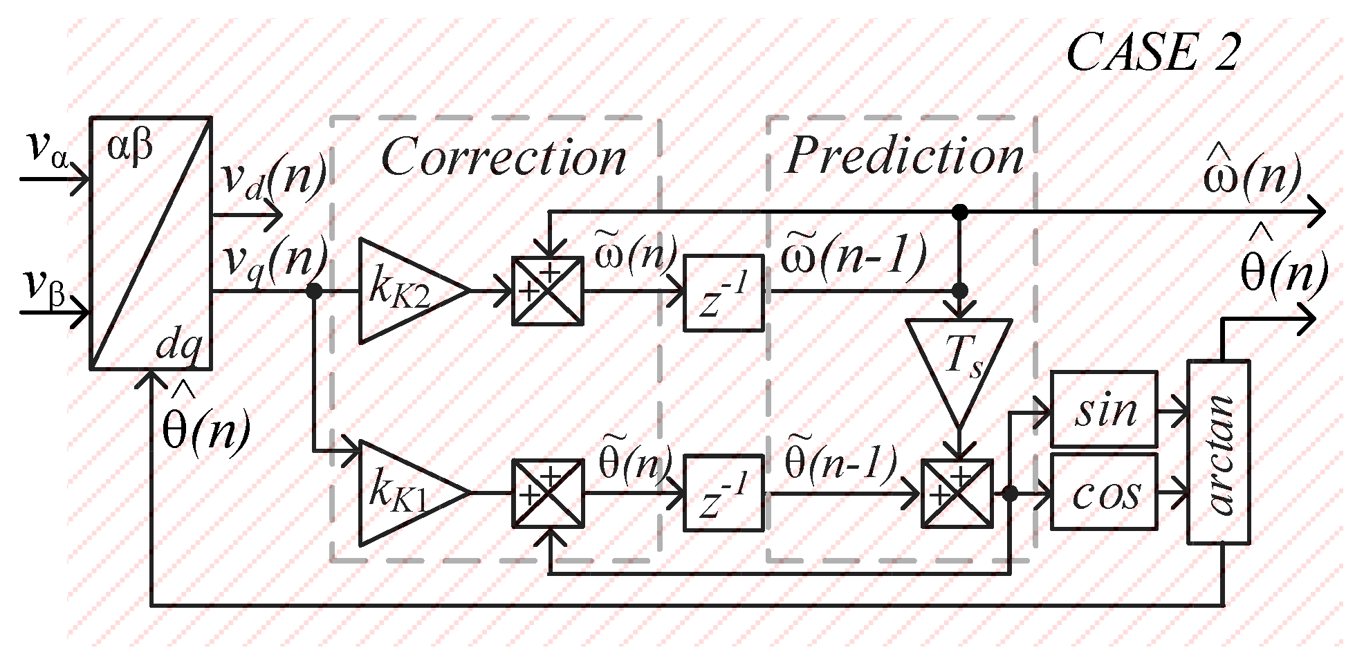
2.1. Kalman Filter Based Two-State Prediction Model
2.2. Modeling, Design Constraints and Procedure
3. Design Example
4. Comparative Analysis of the Proposed System
5. Experimental Validation of the System
6. Conclusions
Author Contributions
Funding
Acknowledgments
Conflicts of Interest
References
- Blaabjerg, F.; Teodorescu, R.; Liserre, M.; Timbus, A. Overview of Control and Grid Synchronization for Distributed Power Generation Systems. IEEE Trans. Ind. Electron. 2006, 53, 1398–1409. [Google Scholar] [CrossRef]
- Han, Y.; Luo, M.; Zhao, X.; Guerrero, J.M.; Xu, L.; Han, Y.; Luo, M.; Zhao, X.; Guerrero, J.M.; Xu, L. Comparative Performance Evaluation of Orthogonal-Signal-Generators-Based Single-Phase PLL Algorithms–A Survey. IEEE Trans. Power Electron. 2015, 31, 3932–3944. [Google Scholar] [CrossRef]
- Golestan, S.; Monfared, M.; Freijedo, F.D.; Guerrero, J.M. Dynamics Assessment of Advanced Single-Phase PLL Structures. IEEE Trans. Ind. Electron. 2012, 60, 2167–2177. [Google Scholar] [CrossRef]
- Shitole, A.B.; Suryawanshi, H.M.; Sathyan, S. Comparative evaluation of synchronization techniques for grid interconnection of renewable energy sources. In Proceedings of the IECON 2015-41st Annual Conference of the IEEE Industrial Electronics Society, Yokohama, Japan, 9–12 November 2015; pp. 1436–1441. [Google Scholar]
- Xiao, F.; Dong, L.; Li, L.; Liao, X. Fast voltage detection method for grid-tied renewable energy generation systems under distorted grid voltage conditions. IET Power Electron. 2017, 10, 1487–1493. [Google Scholar] [CrossRef]
- Guo, C.; Liu, W.; Zhao, C.; Iravani, R. A Frequency-Based Synchronization Approach for the VSC-HVDC Station Connected to a Weak AC Grid. IEEE Trans. Power Deliv. 2017, 32, 1460–1470. [Google Scholar] [CrossRef]
- Carrasco, J.; Franquelo, L.G.; Bialasiewicz, J.; Galvan, E.; Portillo, R.; Prats, M.; Leon, J.I.; Moreno, N. Power-Electronic Systems for the Grid Integration of Renewable Energy Sources: A Survey. IEEE Trans. Ind. Electron. 2006, 53, 1002–1016. [Google Scholar] [CrossRef]
- Golestan, S.; Monfared, M.; Freijedo, F.D.; Guerrero, J.M. Design and Tuning of a Modified Power-Based PLL for Single-Phase Grid-Connected Power Conditioning Systems. IEEE Trans. Power Electron. 2012, 27, 3639–3650. [Google Scholar] [CrossRef]
- Maniatopoulos, M.; Lagos, D.; Kotsampopoulos, P.; Hatziargyriou, N. Combined control and power hardware in-the-loop simulation for testing smart grid control algorithms. IET Gener. Transm. Distrib. 2017, 11, 3009–3018. [Google Scholar] [CrossRef]
- Kunzler, L.M.; Lopes, L.A.C. Power balance technique for cascaded H-bridge multilevel cells in a hybrid power amplifier with wide output voltage range. In Proceedings of the 2018 IEEE International Conference on Industrial Technology (ICIT), Lyon, France, 20–22 February 2018; pp. 800–805. [Google Scholar]
- Kunzler, L.M.; Lopes, L.A.C. Hybrid Single Phase Wide Range Amplitude and Frequency Detection with Fast Reference Tracking. In Proceedings of the 2019 IEEE 28th International Symposium on Industrial Electronics (ISIE), Vancouver, BC, Canada, 12–14 June 2019; pp. 878–883. [Google Scholar] [CrossRef]
- Kunzler, L.M.; Lopes, L.A.C. Algorithm for Improving Power Balance for Cascaded H-Bridge Multilevel under Staircase Modulation for Linear Loads. In Proceedings of the IECON 2019-45th Annual Conference of the IEEE Industrial Electronics Society, Lisbon, Portugal, 14–17 October 2019; Volume 1, pp. 6066–6071. [Google Scholar]
- Singh, B.P.; Arya, S.R. Implementation of Single-Phase Enhanced Phase-Locked Loop-Based Control Algorithm for Three-Phase DSTATCOM. IEEE Trans. Power Deliv. 2013, 28, 1516–1524. [Google Scholar] [CrossRef]
- Zhang, Q.; Sun, X.-D.; Zhong, Y.; Matsui, M.; Ren, B.-Y. Analysis and Design of a Digital Phase-Locked Loop for Single-Phase Grid-Connected Power Conversion Systems. IEEE Trans. Ind. Electron. 2010, 58, 3581–3592. [Google Scholar] [CrossRef]
- Masadeh, M.A.; Amitkumar, K.S.; Pillay, P. Power Electronic Converter-Based Induction Motor Emulator Including Main and Leakage Flux Saturation. IEEE Trans. Transp. Electrif. 2018, 4, 483–493. [Google Scholar] [CrossRef]
- Amitkumar, K.S.; Thike, R.; Pillay, P. Linear Amplifier-Based Power-Hardware-in-the-Loop Emulation of a Variable Flux Machine. IEEE Trans. Ind. Appl. 2019, 55, 4624–4632. [Google Scholar] [CrossRef]
- IEEE Standard for Interconnection and Interoperability of Distributed Energy Resources with Associated Electric Power Systems Interfaces; IEEE-SASB Coordinating Committees: Piscataway, NJ, USA, 2018. [CrossRef]
- Cossutta, P.; Raffo, S.; Cao, A.; DiTaranto, F.; Aguirre, M.P.; Valla, M.I. High speed single phase SOGI-PLL with high resolution implementation on an FPGA. In Proceedings of the 2015 IEEE 24th International Symposium on Industrial Electronics (ISIE), Janeiro, Brazil, 3–5 June 2015; pp. 1004–1009. [Google Scholar]
- Ciobotaru, M.; Teodorescu, R.; Blaabjerg, F. A New Single-Phase PLL Structure Based on Second Order Generalized Integrator. In Proceedings of the 37th IEEE Power Electronics Specialists Conference, Jeju, Korea, 18–22 June 2006. [Google Scholar]
- Golestan, S.; Guerrero, J.M.; Vidal, A.; Yepes, A.G.; Doval-Gandoy, J.; Freijedo, F.D.; Golestam, S.; Guerrero, J.M.; Vidal, A.; Yepes, A.G.; et al. Small-Signal Modeling, Stability Analysis and Design Optimization of Single-Phase Delay-Based PLLs. IEEE Trans. Power Electron. 2015, 31, 3517–3527. [Google Scholar] [CrossRef]
- Hou, M. Estimation of Sinusoidal Frequencies and Amplitudes Using Adaptive Identifier and Observer. IEEE Trans. Autom. Control. 2007, 52, 493–499. [Google Scholar] [CrossRef]
- Yazdani, D.; Bakhshai, A.; Joos, G.; Mojiri, M. A nonlinear adaptive synchronization technique for single-phase grid-connected converters. In Proceedings of the 2008 IEEE Power Electronics Specialists Conference, Rhodes, Greece, 15–19 June 2008; pp. 4076–4079. [Google Scholar]
- Yin, G.; Guo, L.; Li, X. An Amplitude Adaptive Notch Filter for Grid Signal Processing. IEEE Trans. Power Electron. 2012, 28, 2638–2641. [Google Scholar] [CrossRef]
- Robles, E.; Ceballos, S.; Pou, J.; Martín, J.L.; Zaragoza, J.; Ibañez, P. Variable-Frequency Grid-Sequence Detector Based on a Quasi-Ideal Low-Pass Filter Stage and a Phase-Locked Loop. IEEE Trans. Power Electron. 2010, 25, 2552–2563. [Google Scholar] [CrossRef]
- Robles, E.; Pou, J.; Ceballos, S.; Zaragoza, J.; Martín, J.L.; Ibañez, P. Frequency-Adaptive Stationary-Reference-Frame Grid Voltage Sequence Detector for Distributed Generation Systems. IEEE Trans. Ind. Electron. 2010, 58, 4275–4287. [Google Scholar] [CrossRef]
- Picardi, C.; Sgro, D.; Gioffre, G. A simple and low-cost PLL structure for single-phase grid-connected inverters. SPEEDAM 2010 2010, 358–362. [Google Scholar] [CrossRef]
- Burger, B.; Engler, A. Fast signal conditioning in single phase systems. In Proceedings of the 9th European Conference on Power Electronics and Applications, Graz, Austria, 27–29 August 2001. [Google Scholar]
- Ozdemir, A.; Vural, C.; Yazici, I. Fast and robust software-based digital phase-locked loop for power electronics applications. IET Gener. Transm. Distrib. 2013, 7, 1435–1441. [Google Scholar] [CrossRef]
- Golestan, S.; Guerrero, J.M.; Vasquez, J.C. Steady-State Linear Kalman Filter-Based PLLs for Power Applications: A Second Look. IEEE Trans. Ind. Electron. 2018, 65, 9795–9800. [Google Scholar] [CrossRef]
- Vila-Valls, J.; Closas, P.; Navarro, M.; Fernández-Prades, C. Are PLLs dead? A tutorial on kalman filter-based techniques for digital carrier synchronization. IEEE Aerosp. Electron. Syst. Mag. 2017, 32, 28–45. [Google Scholar] [CrossRef]
- Silva, S.; Lopes, B.; Filho, B.C.; Campana, R.; Boaventura, W. Performance evaluation of PLL algorithms for single-phase grid-connected systems. In Proceedings of the 39th IAS Annual Meeting, Seattle, WA, USA, 3–7 October 2004. [Google Scholar] [CrossRef]
- Arruda, L.N.; Silva, S.M.; Filho, B.J.C. PLL structures for utility connected systems. In Proceedings of the Conference Record of the 2001 IEEE Industry Applications Conference 36th IAS Annual Meeting (Cat No 01CH37248) IAS-01, Chicago, IL, USA, 30 September–4 October 2001. [Google Scholar] [CrossRef]
- Karimi-Ghartemani, M.; Iravani, M. A Method for Synchronization of Power Electronic Converters in Polluted and Variable-Frequency Environments. IEEE Trans. Power Syst. 2004, 19, 1263–1270. [Google Scholar] [CrossRef]
- Karimi-Ghartemani, M.; Iravani, M. A new phase-locked loop (PLL) system. In Proceedings of the 44th IEEE 2001 Midwest Symposium on Circuits and Systems. MWSCAS 2001 (Cat. No.01CH37257), Dayton, OH, USA, 14–17 August 2001; Volume 1, pp. 421–424. [Google Scholar] [CrossRef]
- Reza, S.; Ciobotaru, M.; Agelidis, V. Robust technique for accurate estimation of single-phase grid voltage fundamental frequency and amplitude. IET Gener. Transm. Distrib. 2015, 9, 183–192. [Google Scholar] [CrossRef]
- Xiong, L.; Zhuo, F.; Wang, F.; Liu, X.; Zhu, M. A Fast Orthogonal Signal-Generation Algorithm Characterized by Noise Immunity and High Accuracy for Single-Phase Grid. IEEE Trans. Power Electron. 2015, 31, 1847–1851. [Google Scholar] [CrossRef]
- Ikken, N.; Bouknadel, A.; Haddou, A.; Tariba, N.-E.; El Omari, H.; El Omari, H. PLL Synchronization Method Based on Second-Order Generalized Integrator for Single Phase Grid Connected Inverters Systems during Grid Abnormalities. In Proceedings of the 2019 International Conference on Wireless Technologies, Embedded and Intelligent Systems (WITS), Fez, Morocco, 3–5 April 2019; pp. 1–5. [Google Scholar] [CrossRef]
- Bei, T.-Z.; Wang, P. Robust frequency-locked loop algorithm for grid synchronisation of single-phase applications under distorted grid conditions. IET Gener. Transm. Distrib. 2016, 10, 2593–2600. [Google Scholar] [CrossRef]
- Shah, S.; Parsa, L. Small-signal modeling of single-phase PLLs using harmonic signal-flow graphs. In Proceedings of the 2017 IEEE Energy Conversion Congress and Exposition (ECCE), Cincinnati, OH, USA, 1–5 October 2017; pp. 4989–4995. [Google Scholar] [CrossRef]
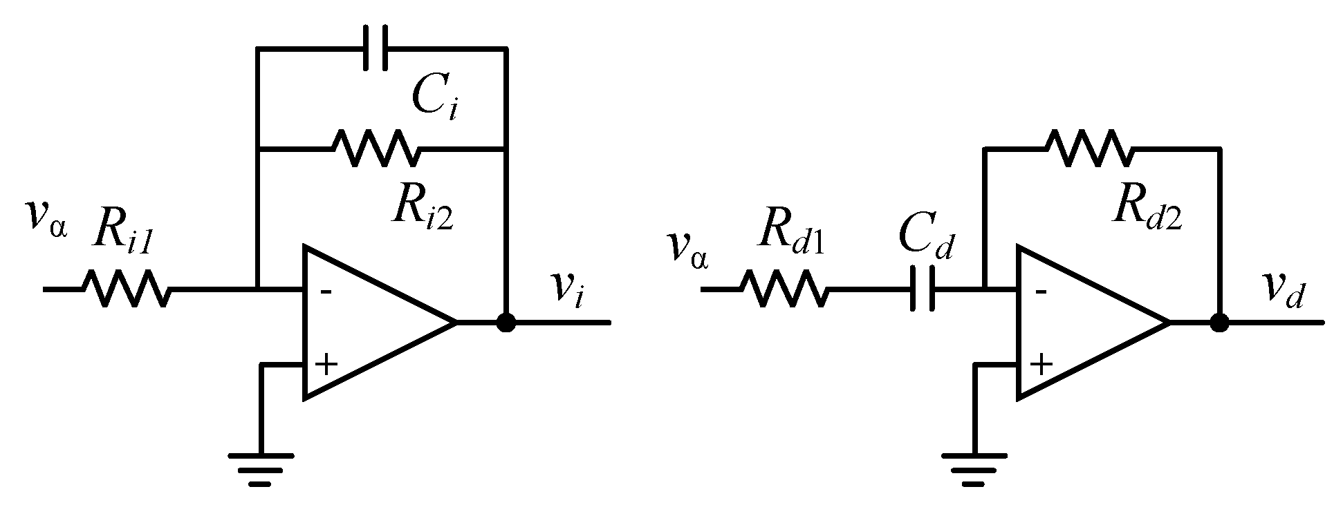
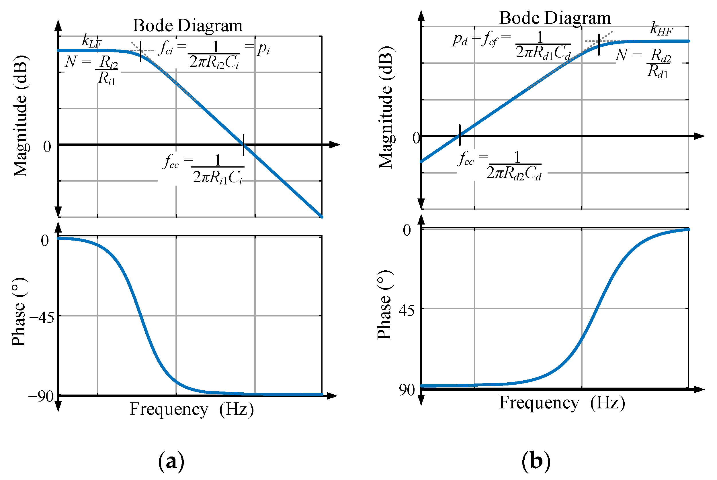
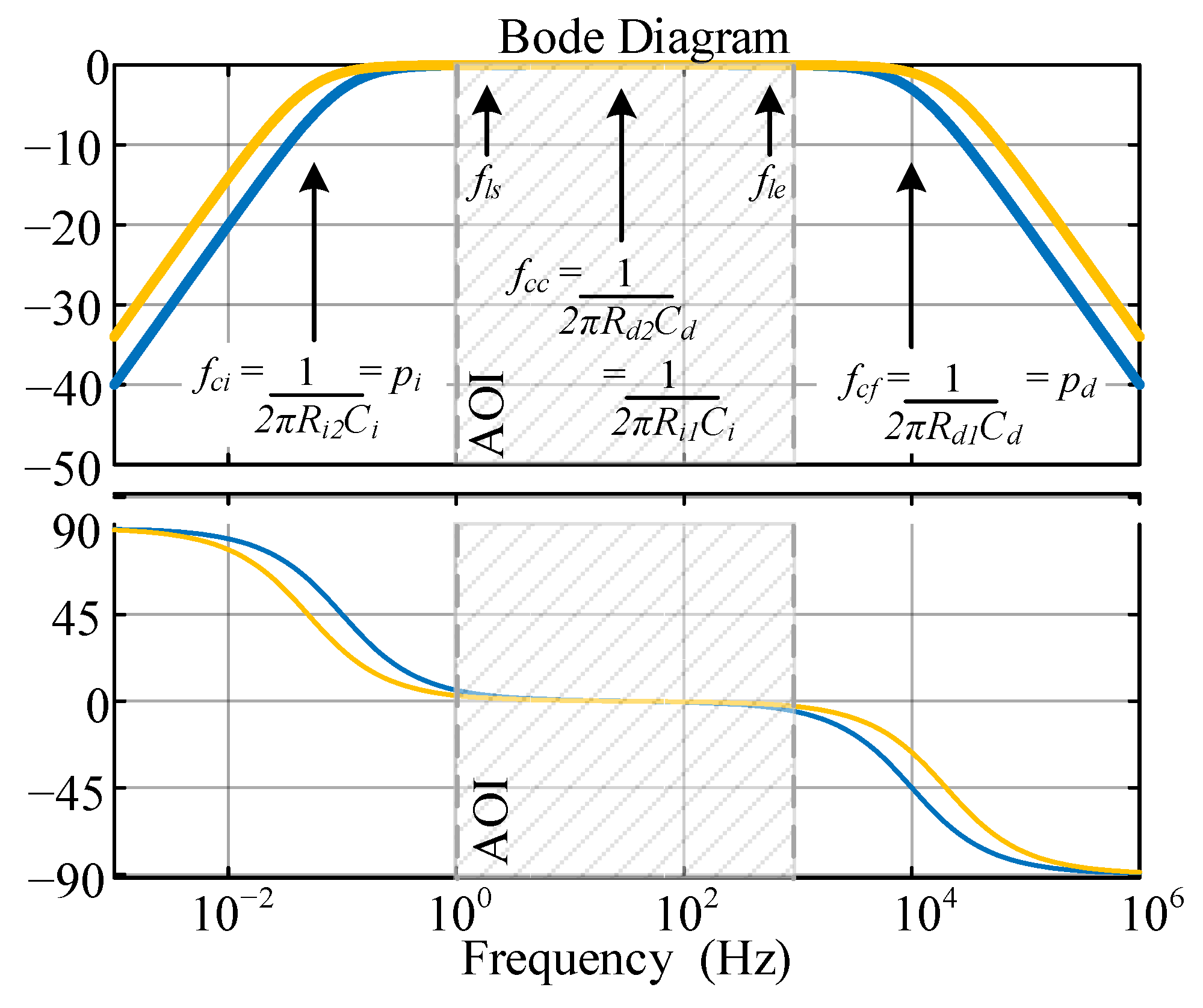
- Integrator Circuit. Analog Engineer’s Circuit: Amplifiers (Application Report No. SBOA275A), February 2018 (revised January 2019). Available online: http://www.ti.com/lit/an/sboa275a/sboa275a.pdf (accessed on 24 August 2020).
- Differentiator Circuit. Analog Engineer’s Circuit: Amplifiers (Application Report No. SBOA276A), February 2018 (revised January 2019). Available online: http://www.ti.com/lit/an/sboa275a/sboa276a.pdf (accessed on 24 August 2020).


© 2020 by the authors. Licensee MDPI, Basel, Switzerland. This article is an open access article distributed under the terms and conditions of the Creative Commons Attribution (CC BY) license (http://creativecommons.org/licenses/by/4.0/).
Share and Cite
Kunzler, L.M.; Lopes, L.A.C. Wide Frequency Band Single-Phase Amplitude and Phase Angle Detection Based on Integral and Derivative Actions. Electronics 2020, 9, 1578. https://doi.org/10.3390/electronics9101578
Kunzler LM, Lopes LAC. Wide Frequency Band Single-Phase Amplitude and Phase Angle Detection Based on Integral and Derivative Actions. Electronics. 2020; 9(10):1578. https://doi.org/10.3390/electronics9101578
Chicago/Turabian StyleKunzler, Luccas M., and Luiz A. C. Lopes. 2020. "Wide Frequency Band Single-Phase Amplitude and Phase Angle Detection Based on Integral and Derivative Actions" Electronics 9, no. 10: 1578. https://doi.org/10.3390/electronics9101578
APA StyleKunzler, L. M., & Lopes, L. A. C. (2020). Wide Frequency Band Single-Phase Amplitude and Phase Angle Detection Based on Integral and Derivative Actions. Electronics, 9(10), 1578. https://doi.org/10.3390/electronics9101578