Article

Positioning Using IRIDIUM Satellite Signals of Opportunity in Weak Signal Environment

School of Electronic and Information Engineering, Beihang University (BUAA), Beijing 100191, China
*
Author to whom correspondence should be addressed.
Electronics 2020, 9(1), 37; https://doi.org/10.3390/electronics9010037
Submission received: 9 December 2019 / Revised: 24 December 2019 / Accepted: 25 December 2019 / Published: 27 December 2019
(This article belongs to the Special Issue Theory and Applications in Digital Signal Processing)

Abstract

:
In order to get rid of the dependence of the navigation and positioning system on the global navigation satellite system (GNSS), radio, television, satellite, and other signals of opportunity (SOPs) can be used to achieve receiver positioning. The space-based SOPs based on satellites offer better coverage and availability than ground-based SOPs. Based on the related research of Iridium SOPs positioning in the open environment, this paper mainly focuses on the occluded environment and studies the Iridium SOPs positioning technique in weak signal environment. A new quadratic square accumulating instantaneous Doppler estimation algorithm (QSA-IDE) is proposed after analysing the orbit and signal characteristics of the Iridium satellite. The new method can improve the ability of the Iridium weak signal Doppler estimation. The theoretical analysis and positioning results based on real signal data show that the positioning based on Iridium SOPs can be realized in a weak signal environment. The research broadens the applicable environment of the Iridium SOPs positioning, thereby improving the availability and continuity of its positioning.

1. Introduction

The new methods for receiver positioning based on abundant and various frequency signals have emerged in recent years. This new positioning technique is termed opportunistic navigation (OpNav) [1,2] and collaborative opportunistic navigation (COpNav) [3]. The navigation via signals of opportunity (NAVSOP) program made by the UK defense firm BAE Systems in 2012 is the typical system. The US Defense Advanced Research Projects Agency (DARPA) also presents a new program, all source positioning and navigation (ASPN), to research the correlation technique. These systems treat the same signals used by mobile phones, TVs, and other radio systems as the radiation sources instead of navigation satellite signals to realize receiver positioning. It can get rid of dependence on the Global Navigation Satellite System (GNSS), or as a new method for overcoming the situation that GNSS does not work. Space-based low earth orbit (LEO) communications satellite signals, as the new SOPs, have some important advantages in terms of more availability and better coverage than for ground-based SOPs. Plentiful non-GNSS satellites are operational today; IRIDIUM [4], GLOBALSATR [5], and ORBCOMM [6] are typical representatives. The related institutions plan to launch a large number of low earth orbit satellites [7].
The Iridium SOPs positioning can still provide location services when GNSS does not work due to interference and other effects. It also can be treated as a full standalone backup of the GNSS. The Iridium signals are generally stronger than the GNSS satellite signals. However, it also encounters signal attenuation caused by interference and signal occlusion. In a weak signal environment, the traditional method of positioning based on Iridium satellite SOPs may fail to capture the signals. As a result, the receiver cannot offer a location service since failing to get the positioning observation information. This situation limits the field of application of this technology. Therefore, this paper mainly studies the method of positioning using Iridium satellite SOPs in weak signal environment.
Before realizing receiver positioning based on Iridium satellite SOPs, we need to measure the positioning observation information, Doppler-shift. Therefore, the difficulty of positioning using Iridium satellite SOPs in weak signal environment lies in accuracy estimation of signal Doppler-shift. The main reason is that Iridium satellite SOPs have a partially known characterization, which means the Doppler-shift estimation in weak signal environment only bases on the limited information. On the other hand, unlike traditional GNSS signals, Iridium satellite transmits discontinuous time-division signals, which will also affect the design of the Doppler-shift estimation in weak signal environment.
The early work of our team researches on the concept of positioning based on the Iridium satellite SOPs and the tests and demonstrations of positioning based on Iridium satellite SOPs in open sky were presented [8]. Based on the previous work, this paper mainly studies the Iridium satellite SOPs positioning technology under the condition of weak signal in the occluded environment.
In Section 2, the Iridium satellite orbit and Iridium signal characteristics are discussed. It can provide a basis for the acquisition of positioning observation information in weak signal environment. In Section 3, a new algorithm of quadratic square accumulating instantaneous Doppler estimation (QSA-IDE) is proposed and its mathematical model is given. In Section 4, we describe the principle of the positioning using Iridium satellite SOPs in weak environment. Experimental results based on real Iridium signals are described in Section 5. Finally, the discussion and conclusions are presented in Section 6 and Section 7.

2. Iridium Satellite Orbit and Signal Characteristics

The number of visible satellites for receiver and positioning measurements are related to the constellation distribution (Iridium satellite orbit) and Iridium signal characteristics, respectively. This section mainly analyzes the Iridium constellation structure and the signal characteristics. It can provide the basis for the Iridium satellite SOPs positioning in weak signal environment.
The concept of Iridium satellite system is first proposed by Bary Bertiger in 1987. The Iridium system, with its constellation of 66 low Earth orbit (LEO) satellites, is a satellite-based, wireless personal communications system, providing voice and data services to virtually any destination on earth [9]. The generation Iridium satellites are almost out of use, expect two satellites are on standby. Iridium Satellite LLC in 2007 announced to launch IRIDIUM NEXT, a second-generation satellite, consisting of 66 active satellites which are used to take the place of the generation Iridium satellites, with another nine in-orbit spares and six on-ground spares. Today, 75 IRIDIUM NEXT satellites are in-orbit operational in six orbital planes, each with an inclination angle of 86.6 degrees to the equatorial plane. The orbit altitude of 70 satellites is 625 km, while the other five satellite orbit altitudes is 720 km. All the satellites have an orbital period of 97 min. At least one satellite can be seen in low latitudes anytime and anywhere.
The Iridium system uses a combination of space division multiple access (SDMA), time division multiple access (TDMA), and frequency division multiple access (FDMA) [10]. The adjacent 12 of the 48 spot beams on each satellite are grouped into a set, to share the total user downlink frequency band based on SDMA and FDMA. For every spot beam, channels are implemented using a TDMA architecture based on time division duplex (TDD) using a time frame. The user uplink and downlink are in different time slots of the same frame of the same TDMA carrier. The frequency accesses are divided into the duplex channel band and the simplex channel band which are used as the traffic channel and signaling channel, respectively. Every time the frame also consists of a simplex part and duplex part. As a result, the simplex signal and duplex signal are in different time slots and different frequency bands. The Iridium frequency allocation and frame structure are shown in Figure 1.
The system uses L-band frequencies of 1616 to 1626.5 MHz for the user link. The frequency band shared by duplex channels is from 1616.0–1626.0 MHz. The 10 MHz band is organized into sub-bands, each of which contains eight frequency accesses. Each sub-band occupies 333.333 kHz (8 * 41.667 kHz, and the guard band is 10.17 kHz). The Iridium is capable of operating with up to 30 sub-bands, containing a total of 240 frequency access. A 12-frequency (12 * 41.667 kHz, and the work band is 31.50 kHz) access band is reserved for the simplex (ring alert and messaging) channels. These channels are located in a globally allocated 500 kHz band between 1626.0 and 1626.5 MHz. The simplex channels of every beam have 12 frequency accesses and 240 frequency accesses of duplex channels that are divided into 12 spot beams equally [11]. As a result, every spot beam has 32 frequency accesses. Every spot beam has 80 duplex channels since every frequency access is with four duplex frequency accesses by TDD. Every satellite can at most get 3840 duplex frequency accesses (4.8 Kbps) since every satellite has 48 beams.
The TDMA frame is in total 90 ms long. It consists of a 20.32 ms downlink timeslot which shares simplex frequency band, followed by four 8.28 ms duplex uplink timeslots and four duplex downlink timeslots that share duplex frequency band. There are 2250 symbols per TDMA frame at a channel burst modulation rate of 25 ksps. A 2400 bps traffic channel uses one uplink and one downlink timeslot per frame [12]. The simplex frequency accesses are only used for downlink signals and they are the only frequencies that may be transmitted during the simplex timeslot. Four messaging channels and one ring alert channel are available during the simplex timeslot.
The simplex signal and duplex signal are both bursts. Each burst has an un-modulated tone, unique word (BPSK) and information data (QPSK) [13]. The simplex bursts (The ring alert signal and the primary message signal) are always transmitted from Iridium satellite and can be passive received by the receiver, which means they can be used for Iridium SOPs positioning. Actually, the IRIDIUM NEXT burst signals of simplex channels that are collected by us are from 6.5 to 20.32 ms.

3. The Estimation of Iridium Satellite Signal Doppler-Shift in Weak Signal Environment

The Doppler-shift measurement is the basis of positioning using Iridium satellite SOPs. A new method of estimating Iridium satellite SOPs Doppler-shift in weak environment is proposed in this section. The detail principle of the new method is given, and every part of the new method is introduced in detail. We first give the principle and the process of the new method. The differences from the traditional Iridium Doppler-shift estimation method and the advantage of the new method are also carried out. Then, the mathematic model of the new method is presented.

3.1. The Principle of Estimating Iridium Satellite Signal Dopller-Shift in Weak Signal Environment

Considering the Iridium satellite SOPs are non-cooperative and non-navigational radio signals, the quadratic square accumulating instantaneous Doppler estimation (QSA-IDE) algorithm is proposed in this paper to realize the Doppler-shift accuracy estimation in weak signal environment. The algorithm squares the signal twice before estimating Doppler-shift. An open-loop measurement method is used to measure Doppler-shift in weak signal environment since the Iridium signals are discontinuous bursts. The QSA-IDE has two parts: Signal detection and signal acquisition. The Iridium bursts in the continuously received data are funded by detection part and the start times of the bursts are locked. The bursts are then intercepted and sent to the acquisition process for Doppler-shift estimation. The principle of QSA-IDE is shown in Figure 2.
The Iridium signals from the antenna are transformed into an intermediate frequency (IF) digital sequence after processing by radio frequency front end (RFFE). The pre-processing module first divides the IF data into consecutive multiple data blocks d i ( i = 1 , , M ) . The length of time of d i is longer than a TDMA frame time. The IF signals in every data block are squared twice and filtered to remove the high frequency part. The new data blocks are denoted by s i ( i = 1 , , M ) . s i may include the quadratic square Iridium signals and the quadratic square noise signals, or only includes the quadratic square noise signals. The quadratic square Iridium signals remove the situation of phase flip caused by the unique word (BPSK) and the information (QPSK). Then, the s i is sent into detection module for detecting whether the Iridium burst is existing or not.
In the detection module, the matched filter is used to judge whether there is a quadratic square Iridium signal. Once finding the target signal, it enters the capture process. At the same time, the quadratic square Iridium signal is intercepted after locking its start and time, and its time stamp and the number of s i are marked. The detection threshold value can be obtained from the pure noise signal in the actual environment. It assumed that total N data blocks have Iridium signals, the first one and the last one are block p and block q , respectively. These Iridium signals are denoted by r k ( k = 1 , , N ; N < M ) . N target signals S k = r k 4 ( k = 1 , , N ; N < M ) are received after finishing the above processing. Then, the quadratic square Iridium signals S k ( k = 1 , , N ; N < M ) are sent to acquisition module.
The main work of acquisition module is Doppler-shift estimation. The center frequency of the quadratic square Iridium signals can be obtained by fast Fourier transform (FFT) processing. The Doppler-shift can be directly calculated since the standard frequency is known. However, the Doppler-shift measurement accuracy is affected by the FFT resolution. This process is called Doppler-shift coarse estimation. The maximum likelihood estimator (MLE) algorithm [14] can be used to realize Doppler-shift fine estimation. This needs a receiver to search the target signals in frequency space. Multiplying the incoming signals with the locally generated duplicated signals, the correlation between the duplicated signals and the incoming signals is detected by signal power that is calculated by coherent integration and squaring. If the frequency of the local carrier matches the incoming signal frequency, the output will be significantly greater than if any of these criteria were not fulfilled. During the search process, the local carrier frequency parameter can be searched within the FFT resolution bandwidth or a wider frequency range. If the maximum output power value exceeds the acquisition threshold, the frequency of the local carrier corresponding to the maximum power is the carrier frequency estimation value of the current signal. The Doppler-shift fine estimation can be easily calculated once the center frequency of the quadratic square Iridium signal is searched successfully.
When the quadratic square processing module in Figure 3 is removed, the principle of the traditional Iridium SOPs Doppler-shift estimation in open sky comes out. In this case, only tone signal in an Iridium burst is used since the unique word signal and the information signal will lead to acquisition failure due to the phase flip. The traditional method of Doppler-shift estimation cannot be used in weak signal environment. It can cause the bursts missing due to the interference caused by signal blockage. The situation that the starting time of the tone signal cannot be precisely locked may appear when the burst is detected. If it happens, the tone signal may contain a unique word signal (BPSK) and information signal (QPSK) which can affect the correlation results of MLE. As a result, the traditional method fails to estimate Doppler-shift.
The new method (QSA-IDE) can overcome the above problems since it squares the Iridium burst twice and the tone signal, unique word signal, and information signal instead of tone are used simultaneously to measure Doppler-shift. On the other hand, the signal power can still be accumulated in weak signal environment by increasing the coherent integration time of MLE since the whole Iridium burst is used. As a result, the QSA-IDE algorithm can measure Doppler-shift in weak signal environment.

3.2. The Mathematical Model of Estimating Iridium Satellite Signal Doppler-Shift in Weak Signal Environment

Let tone signal, unique word signal, and information signal in one burst be denoted by s t o n e , s u n i , and s d . The corresponding time periods are T t o n e , T u n i , T d , respectively t 0 is the starting time of the burst. Then, the expression of the burst signal can be written as:
S I t r i ( t ) = { s t o n e ( t ) ; t 0 t T t o n e s u n i ( t ) ; T t o n e < t T u n i s d ( t ) ; T u n i < t T d
The signals s t o n e , s u n i , and s d are needed to be squared twice, respectively before Doppler-shift estimation when we use the QSA-IDE algorithm. This process is easy for tone signal than for the unique word signal and information signal since the tone is without modulation. The expression of s d ( t ) is:
s d ( t ) = P d d i ( t ) c o s ( 2 π f 0 t + φ d ) + P d d q ( t ) s i n ( 2 π f 0 t + φ d ) + n d ( t )
where P d is the signal power, f 0 is the carrier frequency, φ d is the initial phase. d i and d q are the binary information code sequences of I and Q arms. n d ( t ) is the noise signal. We get the quadratic square signal r d ( t ) by squaring the s d ( t ) twice, and the r d ( t ) can be written as:
r d ( t ) = 3 2 p d 2 1 2 p d 2 cos ( 8 π f 0 t + 4 ϕ d ) + 2 p d 2 d i ( t ) d q ( t ) sin ( 4 π f 0 t +     2 ϕ d ) + 2 p d { p d [ d i ( t ) cos ( 2 π f 0 t + ϕ d ) + d q ( t ) sin ( 2 π f 0 t +     ϕ d ) n d ( t ) + n d 2 ( t ) } + 2 p d d i ( t ) d q ( t ) sin ( 4 π f 0 t + 2 ϕ d ) { p d [ d i ( t )     cos ( 2 π f 0 t + ϕ d ) + d q ( t ) sin ( 2 π f 0 t + ϕ d ) ] n d ( t ) + n d 2 ( t ) } +     { p d [ d i ( t ) cos ( 2 π f 0 t + ϕ d ) + d q ( t ) sin ( 2 π f 0 t + ϕ d ) ] n d ( t ) +     n d 2 ( t ) } 2
We can see that r d ( t ) have four parts, the base band signal is 3 2 p d 2 , the 4 f 0 IF signal is 1 2 p d 2 cos ( 8 π f 0 t + 4 ϕ d ) , the 2 f 0 IF signal is 2 p d 2 d i ( t ) d q ( t ) sin ( 4 π f 0 t + 2 ϕ d ) , and the noise signal. The 4 f 0 IF signal and 2 f 0 IF signal can be obtained, respectively by filtering. However, the d i ( t ) d q ( t ) in 2 f 0 IF signal can cause the phase flip, which means the coherent integration in signal acquisition will be affected. This situation will not happen for 4 f 0 IF signal, which means we can use this signal to estimate Doppler-shift. After filtering, we get:
m d ( t ) = 1 2 P d 2 cos ( 8 π f 0 t + 4 φ d ) + N d ( t )
where m d ( t ) denotes the 4 f 0 IF signal and N d ( t ) is the noise.
The expression of s u n i ( t ) is:
s u n i ( t ) = 2 P u n i d u n i ( t ) c o s ( 2 π f 0 t + φ u n i ) + n u n i ( t )
where P u n i is the signal power, f 0 is the carrier frequency, φ u n i is the initial phase. d u n i ( t ) is the binary information code (789 hex). n u n i ( t ) is the noise signal. We get the quadratic square signal r u n i ( t ) by squaring the s u n i ( t ) twice, and the r u n i ( t ) can be written as:
r u n i ( t ) = 3 2 P u n i 2 + 1 2 P u n i 2 cos ( 8 π f 0 t + 4 φ u n i ) + 2 P u n i 2 cos ( 4 π f 0 t + 2 φ u n i ) + ( 2 2 P u n i d u n i ( t ) n u n i ( t ) cos ( 2 π f 0 t + φ u n i ) + n u n i 2 ( t ) ) [ 2 P u n i cos ( 4 π f 0 t + 2 φ u n i ) + P u n i ] + ( 2 2 P u n i d u n i ( t ) n u n i ( t ) cos ( 2 π f 0 t + φ u n i ) + n u n i 2 ( t ) ) 2
We can see that r u n i ( t ) have four parts, the base band signal is 3 2 P u n i 2 , the 4 f 0 IF signal is 1 2 P u n i 2 cos ( 8 π f 0 t + 4 φ u n i ) , the 2 f 0 IF signal is 2 P u n i 2 cos ( 4 π f 0 t + 2 φ u n i ) , and the noise signal. The 4 f 0 IF signal and 2 f 0 IF signal are both without binary information code sequences, which means they will not cause phase flip in signal acquisition. If we want use both information signal and unique signal to estimate Doppler-shift, their center frequency needs to be the same. As a result, 4 f 0 IF signal is used here and the 2 f 0 IF signal is removed by filtering. Then, we get:
m u n i ( t ) = 1 2 P u n i 2 cos ( 8 π f 0 t + 4 φ u n i ) + N u n i ( t )
where m u n i ( t ) denotes the 4 f 0 IF signal, and N u n i ( t ) is the noise.
Let m t o n e ( t ) denotes the 4 f 0 IF signal of the quadratic square tone signal. Then, the quadratic square Iridium burst signal M I t r i ( t ) can be written as:
M I t r i ( t ) = { m t o n e ( t ) ; t 0 t T t o n e m u n i ( t ) ; T t o n e < t T u n i m d ( t ) ; T u n i < t T d
Let u ( t ) denotes the local signal, the expression is:
u ( t ) = exp ( j 2 π 4 f t )
The signal, after multiplication with the local carrier, assumes the form:
M I t r i ( t ) u ( t ) = P 2 cos ( 8 π f 0 t + 4 φ u n i ) exp ( j 2 π 4 f t ) + N ( t ) exp ( j 2 π 4 f t )
In (10), P is the signal power and N ( t ) is the noise. The high-frequency signal and noise of I and Q arms are removed by integration of the low pass filter. The expression of the result of the coherent integration can be written as [15]:
r p ( n ) = a sin ( 1 2 ( 2 π f e T c o h ) ) 1 2 ( 2 π f e T c o h ) exp j [ 2 π f e ( t 1 + T c o h 2 ) + θ e ]
In (11), a 2 is the mean power of the real input signals, t 1 denotes the starting time of the coherent integration, f e denotes the difference between real signal frequency and local signal frequency, and θ e is the phase difference. The length of the time of the coherent integration is T c o h = T t o n e + T u n i + T d . Expression (11) can also be written as:
r p ( n ) = a sin c ( f e T c o h ) exp j [ 2 π f e ( t 1 + T c o h 2 ) + θ e ]
The expressions of the output of the coherent integration in I and Q arms are:
I p ( n ) = a sin c ( f e T c o h ) cos ( ϕ e )
Q p ( n ) = a sin c ( f e T c o h ) sin ( ϕ e )
where ϕ e = 2 π f e ( t 1 + T c o h 2 ) + θ e is the phase difference. The correlation amplitude between input signal and local duplicated signal can be written as:
E ( n ) = I p 2 ( n ) + Q p 2 ( n ) = a | sin c ( f e T c o h ) |
In (15), we can see that the degree of correlation between real signal and the local signal depend on sin c ( f e T c o h ) . When T c o h is constant, the closer the local signal frequency is to the actual signal frequency, the larger the value of | sin c ( f e T c o h ) | . During the acquisition process, the local signal frequency is continuously adjusted and the maximum correlation amplitude is searched to complete the Doppler-shift estimation.

4. Positioning Using Iridium Satellite SOPs in Weak Signal Environment

The essential elements of Iridium satellite SOPs positioning are observation information acquisition, satellite orbit calculation, and positioning algorithm. The principle of Iridium SOPs positioning in weak signal environment is presented in Figure 3. The solid part denotes the hard platform and the dotted part denotes the software algorithm. A wide-band antenna with a frequency band from 380 to 20 GHz and 5 dB gain connects to a radio frequency front end (RFFE). There are typically three main modules in the software processing: Doppler-shift estimation, satellite orbit reconstruction, and positioning solution. The Doppler-shift measurements are obtained by the QSA-IDE algorithm discussed above. The two-line element set format (TLE) provided from NOARD is used as the Iridium satellite orbital ephemeris. It consists of orbital parameters and time information. We use the SGP4 prediction model to realize the purpose of satellite orbit reconstruction [16].
NOARD periodically updates the Iridium TLE sets once or twice every day. The TLE data can be received directly from the NORAD website celestrak.com. The Iridium satellite position calculated with TLE data is with an error that can be from 100 m to several kilometers. While the corresponding velocity errors are optimistic, the value can be approximately 3 m/s. The position errors and velocity errors are rather smaller in the radial direction than for cross and along direction. After obtaining the Doppler-shift measurements and Iridium orbital, the receiver positioning can be achieved by instantaneous Doppler positioning algorithm, and the position accuracy can be further improved by height aiding.
The Iridium continuously transmits ring alert signal (simplex 7 channel) and primary message signal (simplex 11 channel) to the ground. The quatemary message signal (simplex 3 channel) and tertiary message signal (simplex 4 channel) are occasionally transmitted. In this paper, the simplex 7 and simplex 11 channel signals are used for receiver position, respectively.
The Doppler-shift caused by the relative motion between the satellite and the receiver provides the basis for receiver positioning [17]. The instantaneous Doppler positioning uses multiple intersections of equal Doppler cones to obtain a receiver position instead of using integral Doppler-shift measurements of the hyperbolic positioning method. The Doppler-shift is expressed as [18]:
ρ ˙ k = v k · r k r u r k r u + f u + ε ρ ˙ k
where ρ ˙ k is the Doppler-shift of satellite k and its unit is m/s. r u = [ r u x r u y r u z ] is the receiver position vector and v k = v s i v u denotes the relative velocity vector, v s i = [ v s i x v s i y v s i z ] T and v u = [ v u x v u y v u z ] T are the satellite and receiver velocity vectors, respectively. f u is the receiver clock frequency drift and ε ρ ˙ k is the Doppler-shift error. The navigation equation of the instantaneous Doppler positioning for static receiver is presented here directly which is:
d = [ v 1 · ( r 1 r u 0 ) ( r 1 r u 0 ) T r 1 r u 0 3 v 1 r 1 r u 0 E 3 × 3 1 v k · ( r k r u 0 ) ( r k r u 0 ) T r k r u 0 3 v k r k r u 0 E 3 × 3 1 ] [ Δ r u x Δ r u y Δ r u z Δ f u ] + ε
where d denotes the delta range residual between the Doppler-shift observation vector ρ ˙ = [ ρ ˙ 1 ρ ˙ 2 ρ ˙ k ] T and estimation vector ρ ˙ ^ = [ ρ ˙ ^ 1 ρ ˙ ^ 2 ρ ˙ ^ k ] T . u 0 = [ r u 0 T f u 0 ] is the prior information of the state of receiver. E 3 × 3 is the unit matrix, Δ u = [ Δ r u x Δ r u y Δ r u z Δ f u ] T is the vector update of receiver state, and ε denotes the measurement errors and any approximation errors from the linearization.
Generally, the number of the Iridium satellite that can be seen simultaneously in weak signal environment is less than four in a low latitude area. When the number of visible satellites is insufficient, a multi-epoch positioning method can be used for static receiver [19]. The receiver continuously collects signals in a period of time, and the data is centralized processing, which means the receiver position is calculated with many Doppler-shift measurements of different time of different satellites.

5. Experimental Results

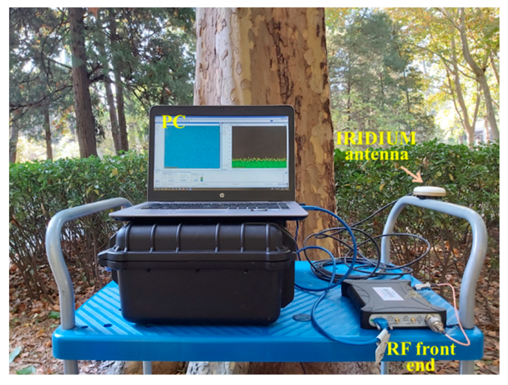
In this section, we present some experimental results based on real Iridium data collected in the weak signal environment. The IRIDIUM NEXT data are collected by a static receiver under a dense forest of BUAA university for 30 min, as shown in Figure 4. The Iridium signals are sent into the software in PC for analyzing and positioning after down-conversion and conversion from analog to digital signals by a RF front end and an Iridium antenna. Compared with the open sky environment, the average power loss of the Iridium signal in this case reaches 8 dB. The IF data collector receives the raw data with a sampling rate of 112 MHz at a RF center frequency of 1626.25 MHz, and the center frequency of the recorded data is 28.25 MHz. The received signals are from two downlink-only channels which are ring alert signal (7 channel) and primary message signal (11 channel). Two channel signals are used for positioning, respectively. The results of Iridium signal Doppler-shift estimation and Iridium SOPs positioning are presented, as described below.

5.1. Estimating Doppler-Shift of Iridium Satellite Signal in Weak Signal Environment

In this section, we will show the Doppler-shift estimation results of the real IRIDIUM NEXT signals by the new QSA-IDE algorithm. The Iridium 7 channel simplex signal, ring alert, can be obtained after filtering the IF data from RFFN. The signal standard frequency is 1626.270833 MHz and the corresponding IF is 28.270833 MHz. We first give the Iridium signal time-domain plot, then Doppler-shift estimation results are carried out.
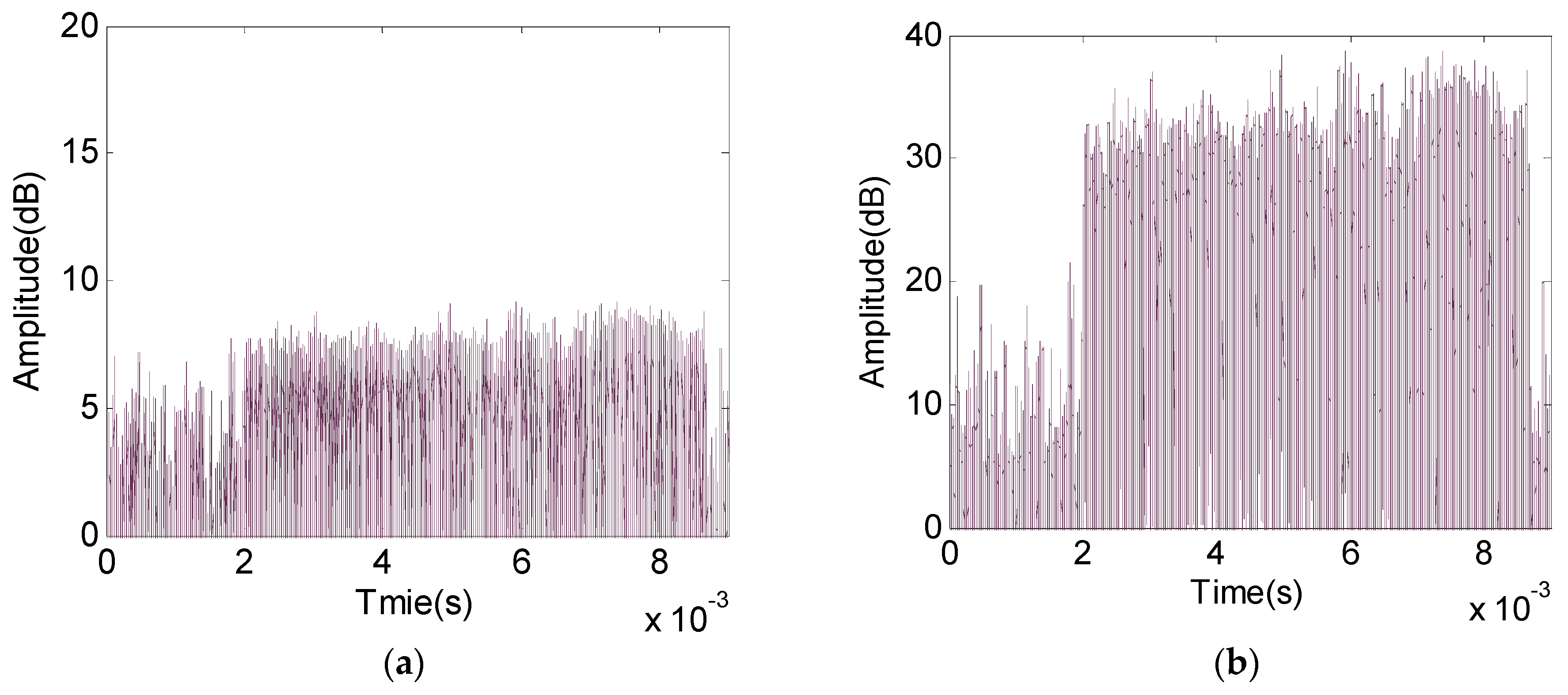
The Iridium signals are the discontinuous burst signals. The time length of the most bursts is about 6.5 ms, and the maximum time length is 20.32 ms. The time domain plot of a 9 ms collected signal after filtering (the filter bandwidth is corresponding to the Iridium ring alert signal bandwidth) is shown in 
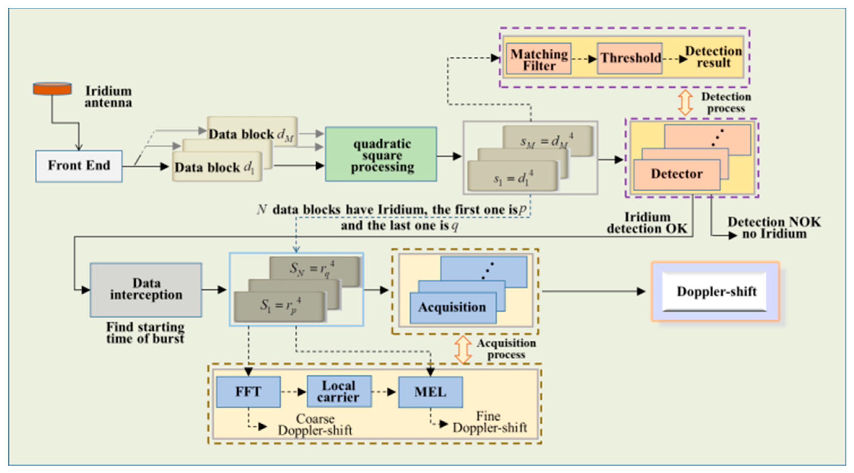
Figure 5a. An Iridium burst signal exists in this 9 ms data. The first 2 ms data is the pure noise signal, then the following 6.6 ms data is the Iridium burst signal, the last 0.4 ms data is the pure noise signal. The amplitude of the Iridium signal is not significantly higher than for noise since the power of the Iridium signal is decreased due to the occlusion environment. The Doppler-shift of this Iridium signal cannot be obtained by the traditional Doppler-shift estimation method since the signal fails to detect, even the tone signal of the Iridium signal that is used by traditional Doppler-shift estimation method cannot be correctly locked. As a result, the Doppler-shift cannot be estimated by the traditional method in weak signal environment. However, Doppler-shift can be estimated by the QSA-IDE algorithm proposed above. The first step of the new method is the quadratic square processing, this can be finished by Equations (1)–(7). Squaring this 9 ms data twice, that is, to multiply it by itself three times. The time domain plot of the quadratic square data after filtering is shown in Figure 5b. It can be seen that the power of the quadratic square Iridium signal is stronger than for noise signal power. The signal-to-noise ratio is very optimistic after quadratic square processing. The quadratic square Iridium signal near the baseband after filtering can be used for Doppler-shift estimation once it was detected by the matched filter. The Doppler-shift estimation result is shown in the following.
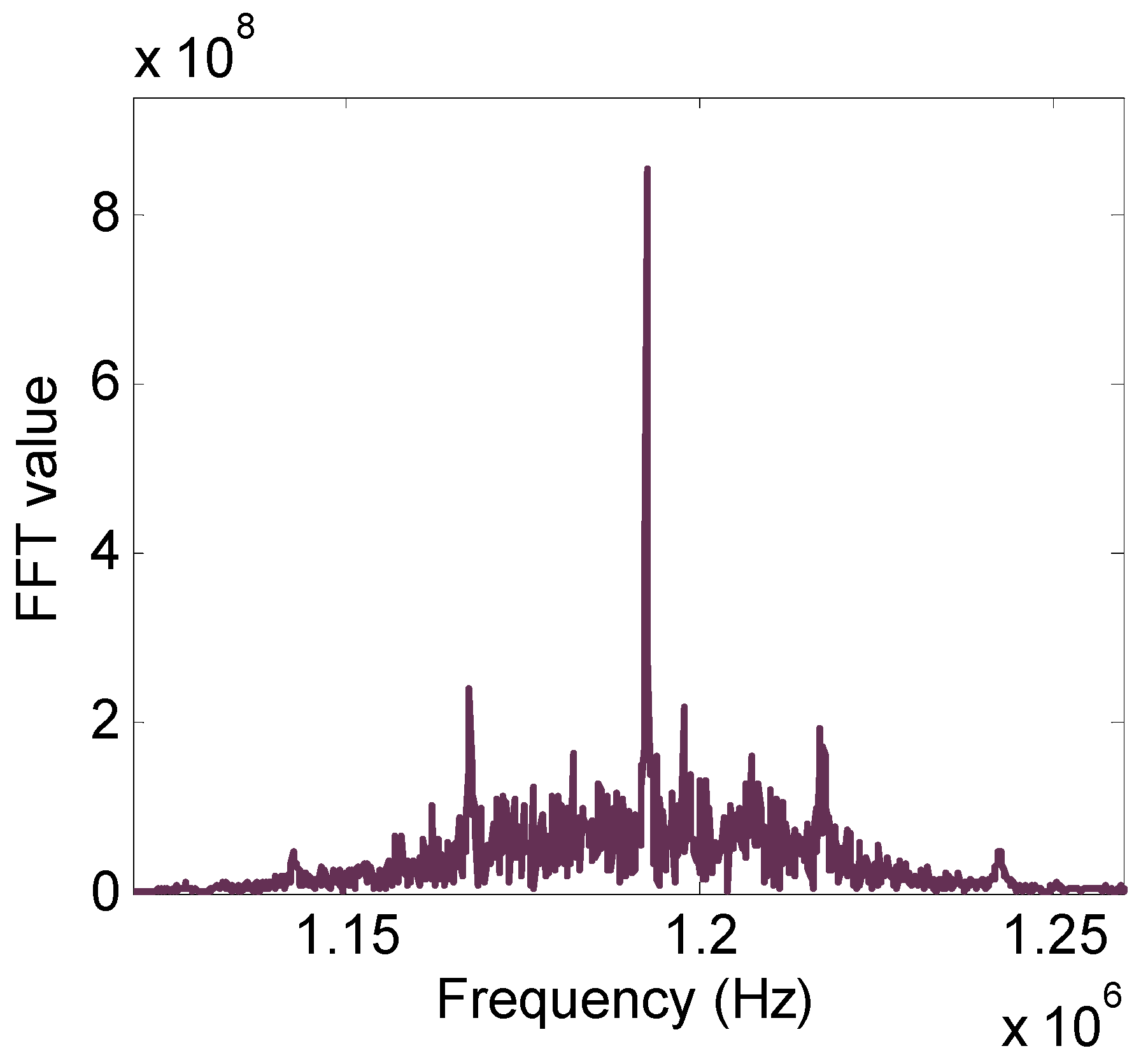
After detecting the quadratic square Iridium signal and locking the starting time, the quadratic square Iridium signal is intercepted and sent into the FFT process module. The FFT results of the quadratic square signal are shown in 
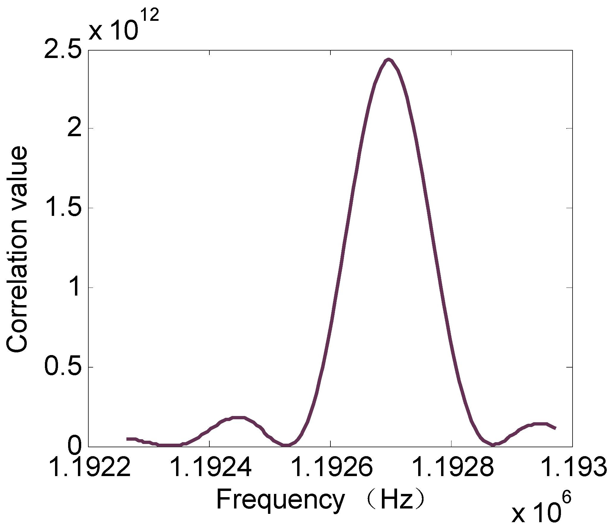
Figure 6. The center frequency of the quadratic square Iridium signal is about 1,192,618.629174 Hz. With the help of the standard frequency of ring alert, we can get the Doppler-shift coarse estimation. However, the Doppler-shift fine estimation is necessary since the error of the Doppler-shift coarse estimation caused by the FFT resolution is insupportable. Generating a local carrier based on the FFT results according to Equation (9). Let it correlate with the quadratic square signal according to Equation (10). The fine center frequency of the quadratic square Iridium signal can be received by using the MLE discussed above. The correlation results can be obtained by Equations (11)–(15), and are shown in Figure 7. The frequency corresponding to the correlation peak is 1,192,697.914173989 Hz, which means the fine frequency estimation of the quadratic square Iridium signal is obtained. The real quadratic square signal of ring alert near the baseband is 1,083,332 Hz. Then, the Doppler-shift of this ring alert burst signal is 27.34147854349727 Hz after simple numerical calculation.
The discussion above gives the detail of the Iridium weak signal Doppler-shift estimation by the new QSA-IDE algorithm and shows that QSA-IDE algorithm can effectively estimate Doppler-shift in weak signal environment. In the collected 30 min IRIDIUM NEXT data, most Iridium signal powers are close to the power of the Iridium signal in Figure 5a, even the power is lower for it. The Doppler-shift curves of the ring alert signal and primer message signal corresponding to the collected 30 min data obtained by QSA-IDE algorithm and the results of positioning using the Iridium satellite SOPs in weak signal environment are shown in the next section.

5.2. Positioning Based on Iridium Satellite SOPs in Weak Signal Environment

In this section, we realize the receiver positioning based on real collected IRIDIUM NEXT. The IRIDIUM NEXT signal Doppler-shift estimation results are given, then the positioning results based on IRIDIUM NEXT SOPs in weak signal environment is carried out.
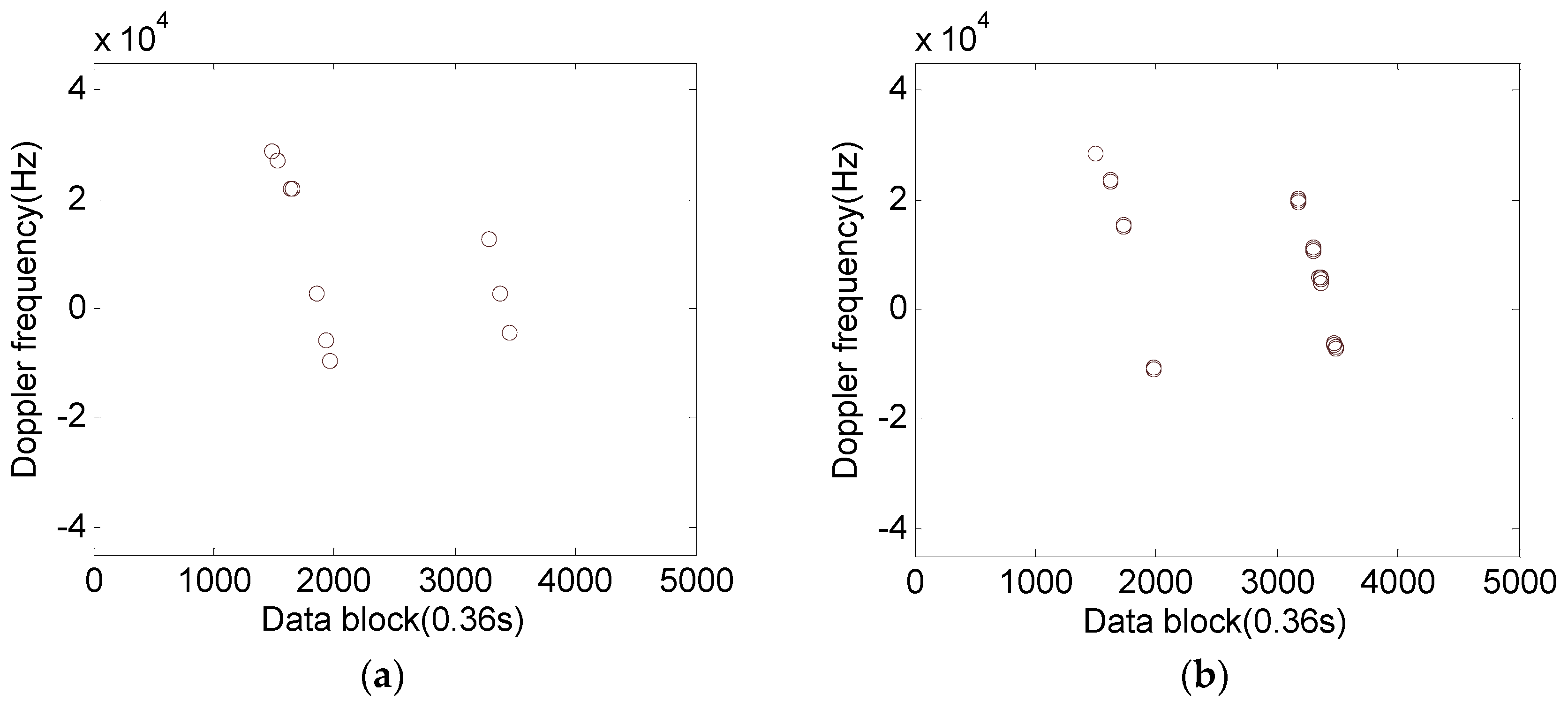
The entire collected IRDIUM NEXT data (30 min) are divided into 5000 continuous data blocks (the time length of every data block is 360 ms), and the Doppler-shift will be estimated if the data block contains the Iridium burst. The Doppler-shift estimation results obtained by the traditional method are shown in Figure 8a,b. The Doppler-shift curves of the ring alert signal (downlink-only 7 channel) is shown in the left plot and the Doppler-shift curves of the primary message signal (downlink-only 11 channel) is shown in the right plot. The x-axis is the data block number and the y-axis is the Doppler-shift (the unit is Hz). Every circle in the plot denotes the Doppler estimation result from the corresponding data block. Generally, the Doppler-shift curve of the satellite is a kid of S-shape curve and the different S-shape curves belong to a different satellite, the Doppler value close to zero means the satellite is located near the top of the receiver, and the Doppler-shift value close to dozens of kHz means the elevation of the satellite is low. We can see that only two IRIDIUM NEXT satellite signal Doppler-shift estimation results can be obtained by the traditional method, which means in this case only two satellites can be seen by the receiver. In this case, when the two IRIDIUM NEXT satellites are near the top of the receiver, the Doppler-shift can be estimated by the traditional method since the signal is strong enough. However, the number of the Doppler-shift estimation results is very small, which means only several strong signals (average power is about 4 dB higher than for noise) can be used by the traditional method. Most signals are weak due to the occlusion environment and fail to estimate Doppler-shift by the traditional method.
In this case, when the static receiver position is calculated by multi-epoch positioning method, the geometric dilution of precision of the instantaneous Doppler positioning algorithm is very negative since the satellites are in the same orbit and few Doppler-shift measurements are obtained. As a result, receiver positioning cannot be achieved since the algorithm does not converge.
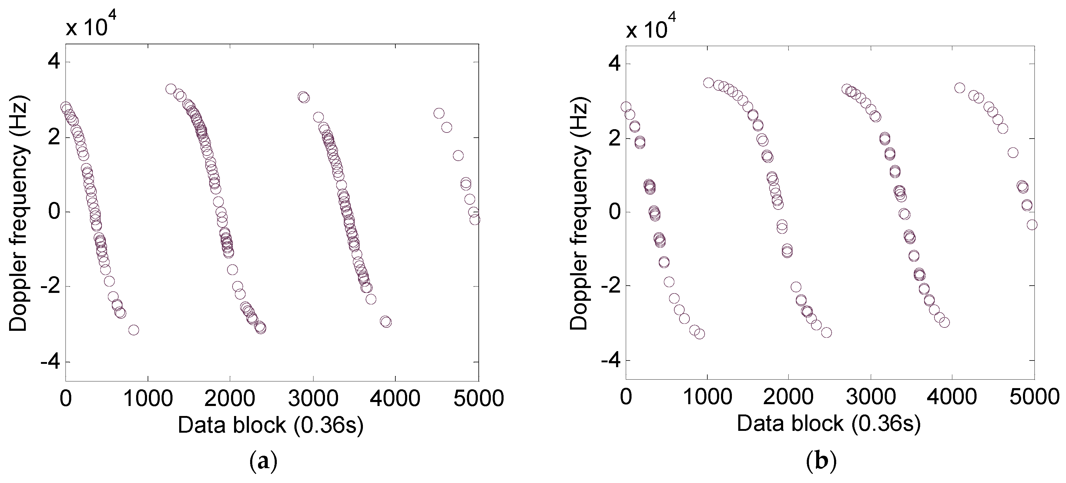
The QSA-IDE algorithm can estimate the IRIDIUM NEXT signal Doppler-shift in weak signal environment, as shown in Figure 9a,b. The meaning of the x-axis and y-axis in Figure 8 and Figure 9 are the same. The Doppler-shift curves of the ring alert signal is shown in Figure 9a and the Doppler-shift curves of the primary message signal is shown in Figure 9b. We can see that four IRIDIUM NEXT satellites can be seen in this case, and both ring alert signal Doppler-shift curves and primary message signal Doppler-shift curves are more optimistic than for the traditional method. The Doppler curves in Figure 9a,b have exactly the same profile since the signals corresponding to every pair of curves belong to the same satellites. The new QSA-IDE method not only can see more Iridium satellites but also significantly increases the visible times of every satellite. The low elevation satellite signal Doppler-shift is also estimated successfully. The first satellite just begins to be seen at low elevation. These four satellites are located at the same orbit since the Doppler-shift curves of all these four satellites have the same shape. Although only one satellite can be viewed simultaneously under the occlusion environment, the Doppler-shift measurements of these satellites are enough for static receiver positioning by the multi-epoch positioning method.
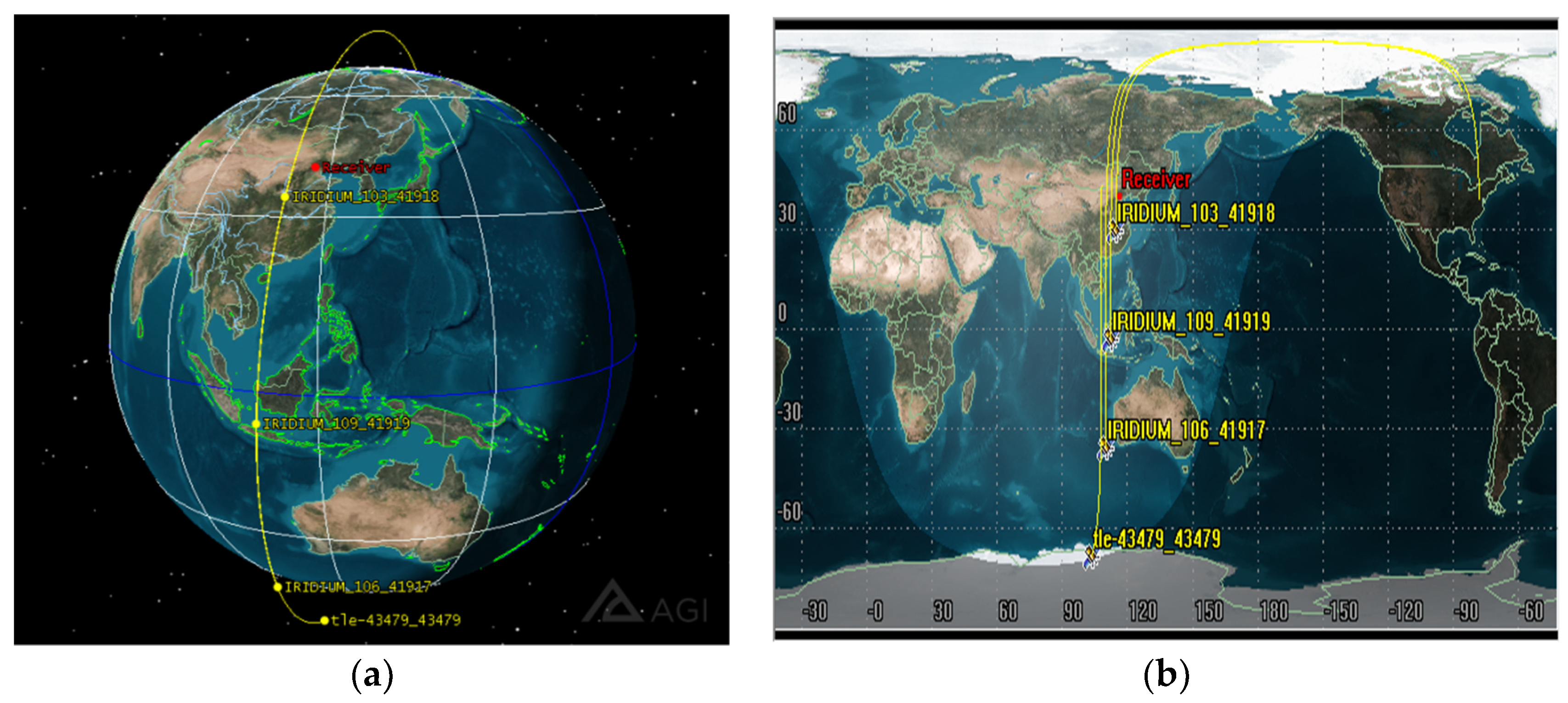
These four IRIDIUM NEXT satellites are simulated with the satellite tool kits (STK). The simulation time is in accordance with the time of the real IRIDIUM NEXT collected. The simulation results corresponding to the starting time of the real IRIDIUM NEXT collected are shown in 
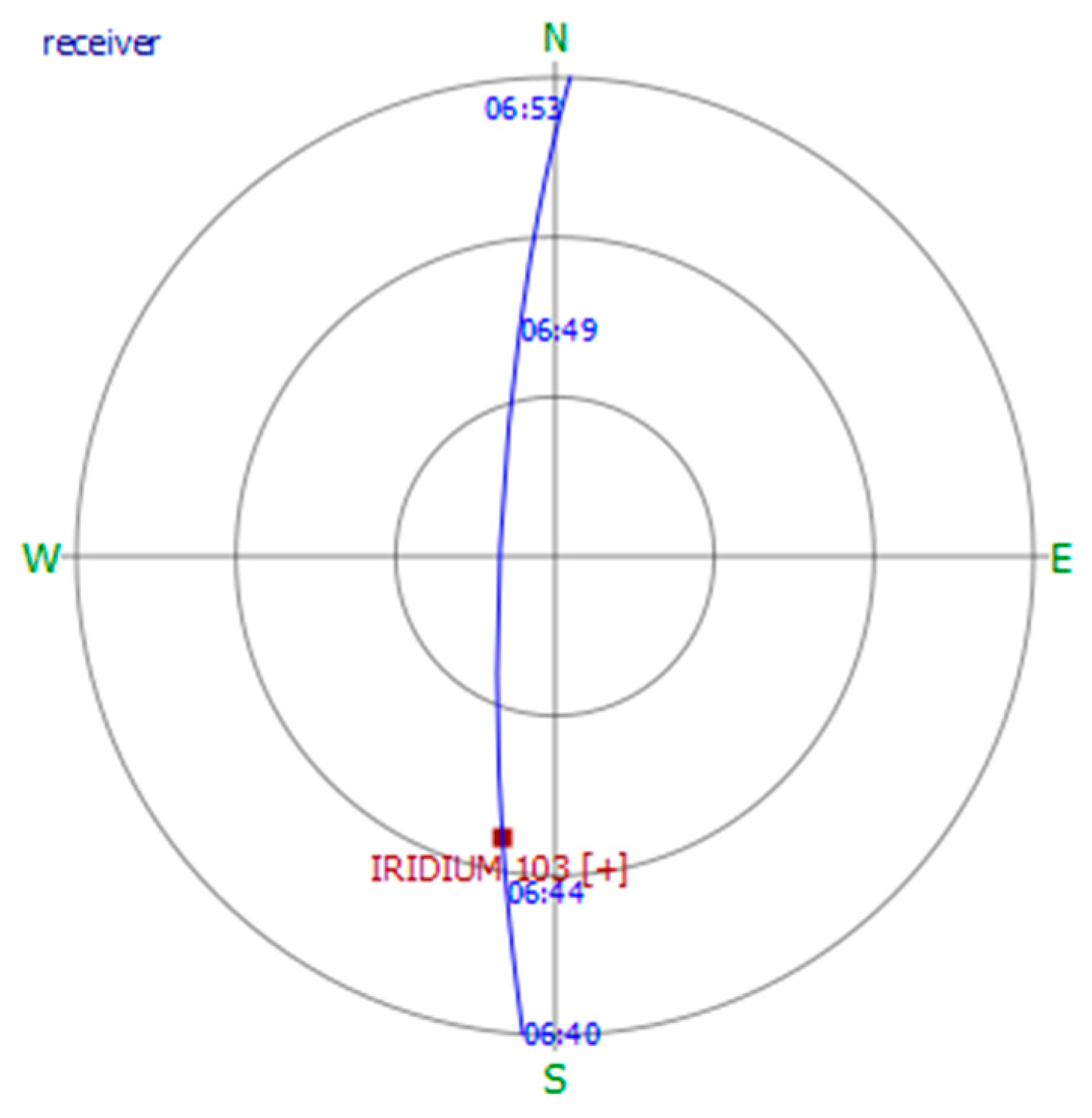
Figure 10a,b. The red point denotes the receiver location and the yellow point denotes the satellite locations. The satellites are IRIDIUM 41918U, IRIDIUM 41919U, IRIDIUM 41917U, and IRIDIUM 43479U. We can see that the first satellite, 41918U, just comes into view at a low elevation location, then following the other three Iridium satellites. These four satellites are located at the same orbit and the corresponding sub-tracks are near the receiver. The conclusion is in accordance with the analysis results from the real Doppler-shift curves discussed above. We give the sky plot by taking the first IRIDIUM NEXT satellite for example, as shown in Figure 11. The red point denotes the Iridium satellite position corresponding to the starting time of the real Iridium data collected and the receiver locates at the central of the circle. In this case, although the receiver is located at an occlusion environment, we can still estimate the Iridium Doppler-shift.
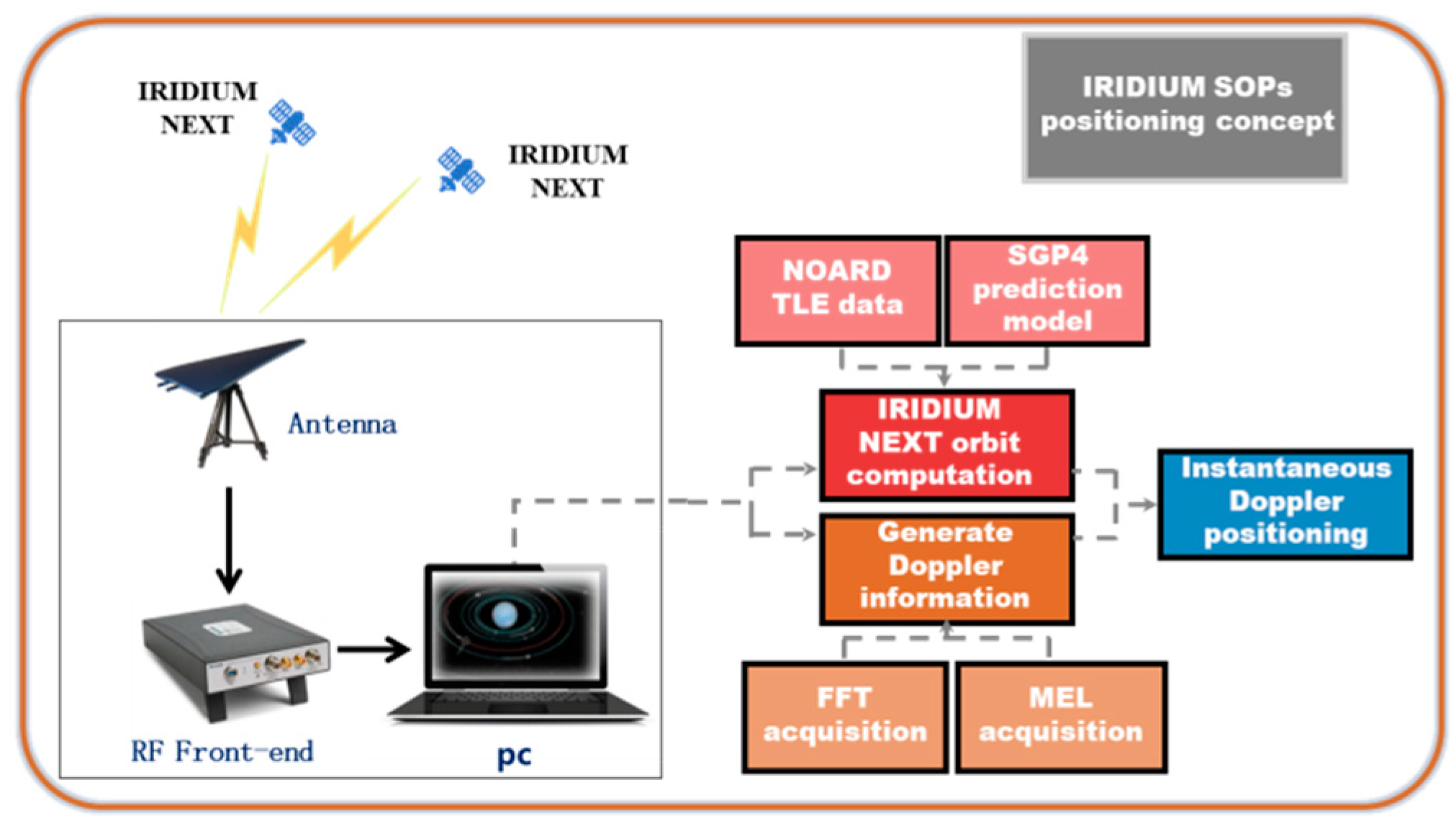
After obtaining the Doppler-shift measurements, we can realize the receiver positioning. The IRIDIUM NEXT TLE data downloaded from the NOARD web are obtained as the satellite ephemerides and the orbital prediction model is used to calculate the Iridium satellite position and velocity. The Doppler positioning and height aiding are used for receiver position calculation. For the static receiver, the multi-epoch positioning method is used here. We use total 25 Doppler-shift measurements to form the positioning solution equations and the least squares (LS) is used to calculate the receiver position. These 25 measurements come from four different satellites. As a result, for every satellite, the measurements corresponding to different moments are used together.
The receiver solutions calculated with different Doppler-shift measurement combinations are different. The Doppler-shift measurement accuracy corresponding to different satellites and different moments are different. Here, the positioning results with different Doppler measurement combinations are shown. Every combination has 25 Doppler measurements from four satellites, and the receiver position calculations are run for a total of 800 times. The positioning error statistic results with the ring alert signal are carried out first. The mean error and root mean square (RMS) are calculated, as shown in Table 1.
It can be seen that compared with the north-direction and the up-direction, the receiver has a larger positioning error in the east-direction. The east-direction average position error reaches 147 m, and the error is with large fluctuations. The mean value of up-direction position error is optimistic, however, the fluctuation range is about 10 m more than the north-error. The 3D position error RMS in this case is about 400 m. The statistical results of height aiding are shown in Table 2.
The positioning performance can be improved with height aiding, especially in the east-direction. The position error mean in the east-direction can be 21 m. However, the fluctuation range of position error in the east-direction is still larger than for north-direction. This is caused by the special IRIDIUM orbital characteristic. As a result, the 2D position error RMS in this case is 198 m. The positioning results presented above are based on the ring alert signal. Then, the receiver position can still be obtained after performing the same step for the primer message signal. The statistical positioning results of height aiding are shown in Table 3.
The 2D position error RMS in this case is 163 m. It can be seen that the positioning error mean value of north-direction in Table 3 is close to the corresponding error mean in Table 2. However, the error mean value of north-direction in Table 2 and Table 3 is different. On the other hand, the positioning error RMS values calculated with the primer message signal are more optimistic than for the ring alert signal. This is because the power of the ring alert signal is generally stronger than for the primer message signal. As a result, the Doppler-shift measurement accuracy of the primer message signal is better than for the ring alert signal, and the fluctuation of positioning error is smaller.
Considering the Doppler-shift measurement accuracy for different satellites and different moments is different, the Kalman filtering (KF) is used to process the least squares (LS) solutions from different Doppler measurement combinations. As a result, the position estimations calculated with the two channel signals are both about 110 m away from the real location. The positioning errors in east-west direction are more optimistic than for south-north direction in two cases. The common features of positioning error are caused by the satellite orbital error.

6. Discussion

We introduce the technique of receiver positioning based on Iridium SOPs in weak signal environment in this paper. Since its point is the Iridium SOPs Doppler-shift estimation in weak signal environment, we present a new method, termed QSA-IDE algorithm, to obtain Doppler-shift after analyzing the Iridium orbital and signal characteristics, and we show the principle and mathematical model of the QSA-IDE algorithm. The concept and principle of Iridium SOPs positioning in weak signal environment also appeared. Finally, we show the test results using the real collected IRIDIUM NEXT data, and the corresponding result analysis.
The OpNav and COpNav have emerged for many years. Using the Iridium satellite to offer location service is very popular in recent years. The Iridium satellite LLC, in 2016, announced that the service termed satellite time and location (STL) based on the Iridium satellite network can provide solutions for time and location. It can aid GPS or replace GPS. Recently, the scholar from Saint Petersburg State University also conducted the research about Iridium Next LEO satellites as an Alternative PNT in GNSS denied environment. These techniques treat the Iridium satellite signals as the cooperation signals instead of SOPs. Many scholars also study the technique of Iridium assisted GNSS, such as improve the GNSS satellite geometry distribution, decrease the time of integer ambiguity solution of the GNSS carrier phase positioning. Our work about Iridium satellite signal positioning treat the Iridium signal as the SOPs and realize positioning with the Iridium satellites alone. Our early work studied the concept of Iridium satellite SOPs positioning in open sky environment. We show the research result of Iridium satellite SOPs positioning in weak signal environment in this paper based on the early work. We show the test results based on real data. The Doppler-shift estimation results suggest the new QSA-IDE algorithm can effectively measure Iridium SOPs Doppler-shift in weak signal environment. The positioning results show, in weak signal environment, that the receiver 2D position accuracy can achieve between 100 and 200 m. The positioning accuracy is reasonable since many error influences are not removed, such as satellite orbital information is calculated with TLE data. Even so, we still realize the positioning under the occlusion environment using Iridium weak SOPs.
Our work in this paper also has shortcomings. The positioning accuracy cannot match GPS. Treating the Iridium signals as the SOPs, the result is that only partially known characterizations, such as lack of satellite ephemeris. However, the satellite orbital errors and other errors should be estimated with the receiver position. The positioning accuracy will be improved. On the other hand, in this paper, only Iridium SOPs are used to realize receiver positioning. There are plentiful satellites operational today, and many of them also have potential for positioning.
Further work on this topic can cover the improvement of positioning accuracy by orbital error correction or the differential positioning technique. Other LEO satellite SOPs are also considered to be used for positioning.

7. Conclusions

This article studies the positioning using Iridium satellite signals in weak signal environment. The Iridium satellite signals here are treated as the non-cooperative SOPs for positioning. The key difficulty of the Iridium satellite SOPs positioning in weak environment is the Doppler-shift estimation. The new method termed QSA-IDE algorithm is proposed to estimate the Iridium satellite SOPs Doppler-shift in weak environment after detailed analysis of the Iridium satellite orbit and signal characteristics. The new algorithm mainly includes signal detection and signal acquisition, the former is used to find Iridium burst signals and the latter is used to estimate Doppler-shift. The quadratic square processing in the new method and the whole Iridium burst signal (including tone signal, unique signal, and information signal) is used to estimate that Doppler-shift are the core of the new algorithm. The mathematical model is created after introducing the principle of the QSA-IDE algorithm. We use the MLE to search Iridium signals and obtain the Doppler-shift fine estimations. The maximum correlation of MLE is not affected by the modulation mode of Iridium signal after quadratic square processing. For the Iridium SOPs positioning, the satellite position and velocity are calculated by the satellite TLE data and SGP4 prediction model, the instantaneous Doppler positioning technique is used after estimating Iridium satellite signal Doppler-shift. The new concept is tested using real collected data.
The real IRIDIUM NEXT satellite data is collected under a dense forest where the Iridium signal is weak due to the occlusion environment. An Iridium antenna and a RF front end are used to obtain the Iridium IF data, and the software in the PC is used to realize Doppler-shift estimation and Iridium SOPs positioning. The Doppler-shift estimation results show that the new algorithm can effectively measure Doppler-shift in weak signal environment compared to the traditional method. It can see enough satellites and increase the number of the Doppler-shift measurement for every satellite. As a result, the new algorithm can used for Iridium SOPs positioning in weak signal while the traditional method is not. By continuously measuring the Iridium SOPs Doppler-shift and combining the satellite orbit information, the receiver positioning results based on real collected data in weak signal environment are carried out. When the Iridium ring alert signal is used, the positioning error mean values of east-direction and north-direction can be 147 and −162 m, while the value is only 58 m corresponding to the up-direction. The positioning error RMS value is larger for east-direction than for north-direction and up-direction. When the height aiding is used, the error mean value of east-direction is only 21 m and the value corresponding to north-direction is −108 m. The error RMS value of east-direction and north-direction is 144 and 137 m, respectively. In this case, the 2D positioning error RMS is 198 m. After performing the same step for the primer message signal, we got the approximate positioning results. In this case, the positioning error mean value of east-direction is −30 m and the value corresponding to the north-direction is −113 m, the 2D positioning error RMS is 163 m. The Kalman filtering is used to average the solutions from different Doppler-shift measurement combinations. As a result, the 2D positioning accuracy in both cases can achieve 110 m. The receiver solutions in two cases are both located at the south of real receiver position, the positioning error in east-west direction are more optimistic than for south-north direction in two cases. The common features of positioning error are caused by the Iridium satellite orbital error.

Author Contributions

Writing—original draft preparation, Conceptualization, Data curation, Investigation, methodology, Software, Writing—review and editing, Z.T.; Conceptualization, Funding acquisition, Resources, Writing—review and editing, H.Q., L.C.; Investigation, C.Z. All authors have read and agreed to the published version of the manuscript.

Funding

This work was supported by the National Science and Technology Innovation Special Zone Project.

Conflicts of Interest

The authors declare no conflict of interest.

References

  1. Pesyna, K.M., Jr.; Kassas, Z.M.; Bhatti, J.A.; Humphreys, T.E. Tightly-coupled opportunistic navigation for deep urban and indoor positioning. In Proceedings of the International Technical Meeting of the Satellite Division of the Institute of Navigation, Portland, OR, USA, 20–23 September 2011; pp. 3065–3616. [Google Scholar]
  2. Yang, C.; Nguyen, T. Self-calibrating positioning location using signals of Opportunities. In Proceedings of the ION GNSS, Savannah, GA, USA, 22–25 September 2009; pp. 1055–1063. [Google Scholar]
  3. Kassas, Z.M.; Humphreys, T.E. Observability analysis of collaborative opportunistic navigation with pseudorange measurements. IEEE Trans. Intell. Transp. Syst. 2013, 1, 260–273. [Google Scholar] [CrossRef]
  4. Pratt, S.R.; Raines, R.A.; Fossa, C.E.; Temple, M.A. An operational and performance overview of the iridium low earth orbit satellite system. IEEE Commun. Surv. Tutor. 1999, 2, 2–10. [Google Scholar] [CrossRef]
  5. Dietrich, F.J.; Metzen, P.; Monte, P. The globalstar cellular satellite system. IEEE Trans. Antennas Propag. 2002, 46, 935–942. [Google Scholar] [CrossRef]
  6. Hara, T. ORBCOMM low Earth orbit mobile satellite communication system. In Proceedings of the TCC’94—Tactical Communications Conference, Fort Wayne, IN, USA, 10–12 May 1994; IEEE: Piscataway, NJ, USA, 2002. [Google Scholar]
  7. Reid, T.G.R.; Neish, A.M.; Walter, T.F.; Enge, P.K. Leveraging Commercial Broadband LEO Constellations for Navigation. In Proceedings of the International Technical Meeting of the Satellite Division of the Institute of Navigation, Portland, OR, USA, 12–16 September 2016; pp. 2300–2314. [Google Scholar]
  8. Tan, Z.Z.; Qin, H.L.; Cong, L.; Zhao, C. New method for positioning using IRIDIUM satellite signals of opportunity. IEEE Access 2019, 7, 83412–83423. [Google Scholar] [CrossRef]
  9. Lemme, P.W.; Glenister, S.M.; Miller, A.W. Iridium(R) aeronautical satellite communications. IEEE Aerosp. Electron. Syst. Mag. 1999, 14, 11–16. [Google Scholar] [CrossRef]
  10. Min, S.Q. Satellite Communication System Engineering Design and Application; Electronics Industry Press: Beijing, China, 2015; pp. 352–361. (In Chinese) [Google Scholar]
  11. ICAO. Manual for ICAO Aeronautical Mobile Satellite (ROUTE) Service Part2-IRIDIUM; Draft v 4.0; ICAO: Montreal, QC, Canada, 2007. [Google Scholar]
  12. Fossa, C.E.; Raines, R.A.; Gunsch, G.H.; Temple, M.A. An Overview of the Iridium Low Earth Orbit (LEO) Satellite System. In Proceedings of the Aerospace and Electronics Conference, Dayton, OH, USA, 17 July 1998; pp. 152–159. [Google Scholar]
  13. Shahriar, C.M.R. A scheme to mitigate interference from Iridium satellite downlink signal captured by omnidirectional antenna array. In Proceedings of the IEEE Antennas and Propagation Society International Symposium, San Diego, CA, USA, 5–11 July 2008; pp. 1–4. [Google Scholar]
  14. Kay, S.M. Fundamentals of Statistical Signal Processing: Estimation Theory; Prentice Hall PTR: Upper Saddle River, NJ, USA, 1993; pp. 129–139. [Google Scholar]
  15. Seco-Granados, G.; Lopez-Salcedo, J.A.; Jimenez-Banos, D.; Lopez-Risueno, G. Challenges in indoor global navigation satellite systems: unveiling its core features in signal processing. IEEE Signal Process. Mag. 2012, 29, 108–131. [Google Scholar] [CrossRef]
  16. Levit, C.; Marshall, W. Improved orbit predictions using two-line elements. Adv. Space Res. 2011, 47, 1107–1115. [Google Scholar] [CrossRef] [Green Version]
  17. Van Diggelen, F. A-GPS: Assisted GPS, GNSS, SBAS; Artech House: Norwood, MA, USA, 2009; pp. 261–264. [Google Scholar]
  18. Kaplan, D.E.; Hegarty, C.J. Understanding GPS Principle and Applications, 2nd ed.; Artech House: Norwood, MA, USA, 2006; pp. 305–345. [Google Scholar]
  19. Zhang, S.X. Theory and Application of GPS Satellite Measurement and Positioning; National University of Defense Technology Press: Changsha, China, 1996; pp. 86–87. (In Chinese) [Google Scholar]
Figure 1. Iridium frequency allocation and frame structure.
Electronics 09 00037 g001
Figure 2. Principle of the quadratic square accumulating instantaneous Doppler estimation algorithm.
Electronics 09 00037 g002
Figure 3. Basic Iridium SOPs positioning principle in weak signal environment.
Electronics 09 00037 g003
Figure 4. IRIDIUM NEXT data collection in weak signal environment.
Electronics 09 00037 g004
Figure 5. Magnitude of collected 9 ms data: (a) Magnitude of the collected data after filtering with the Iridium ring alert signal frequency band; (b) magnitude of collected data after square quadratic square processing and filtering with the Iridium ring alert signal frequency band.
Electronics 09 00037 g005
Figure 6. FFT results of the quadratic square IRIDIUM ring alert signal.
Electronics 09 00037 g006
Figure 7. Correlation results between local carrier and real signal.
Electronics 09 00037 g007
Figure 8. Doppler-shift estimation results of the IRIDIUM NEXT signals obtained by the traditional method: (a) Iridium ring alert signal Doppler-shift estimation results; (b) Iridium primary message signal Doppler-shift estimation results.
Electronics 09 00037 g008
Figure 9. Doppler-shift estimation results of the IRIDIUM NEXT signals obtained by the new method: (a) Iridium ring alert signal Doppler-shift estimation results; (b) Iridium primary message signal Doppler-shift estimation results.
Electronics 09 00037 g009
Figure 10. Simulation results of the four visible IRIDIUM NEXT satellites based on STK: (a) Three-dimensional (3D) graphics of the simulation result; (b) two-dimensional (2D) graphics of the simulation result.
Electronics 09 00037 g010
Figure 11. Sky plot of the first visible IRIDIUM NEXT satellite.
Electronics 09 00037 g011
Table 1. Error statistic results of positioning with the ring alert signal in weak signal environment.
ParametersEast-Error/mNorth-Error/mUp-Error/m
Mean value147−16258
RMS value371149161
Table 2. Error statistic results of positioning with the ring alert signal and height aiding in weak signal environment.
ParametersEast-Error/mNorth-Error/m
Mean value21−108
RMS value144137
Table 3. Error statistic results of positioning with the primer message signal and height aiding in weak signal environment.
ParametersEast-Error/mNorth-Error/m
Mean value−30−113
RMS value121110

