Abstract
This paper describes a compact patch antenna intended for medical body area network. The antenna is fed using a proximity coupling scheme to support the antenna that radiates in the free space and on the human body at the 2.45 GHz ISM band. The conductor plane is placed 2 mm or 0.0163λ0 (λ0 is free space wavelength at 2.45 GHz) below the antenna to reduce backward radiation to the human body. Separation distance must be kept above 2 mm, otherwise, gain of the proposed antenna decreases when antenna is situated on the human body. The L-shape feed line is introduced to overcome impedance mismatch caused by the compact structure. The coupling gap between the proposed antenna and the length of the L-shape feed line are optimized to generate dual resonances mode for wide impedance bandwidth. Simulation results show that specific absorption rate (SAR) of the proposed antenna with L-shape feed line is lower than conventional patch antenna with direct microstrip feed line. The proposed antenna achieves impedance bandwidth of 120 MHz (4.89%) at the center frequency of 2.45 GHz. The maximum gain in the broadside direction is 6.2 dBi in simulation and 5.09 dBi in measurement for antenna in the free space. Wide impedance bandwidth and radiation patterns insensitive to the presence of human body are achieved, which meets the requirement of IoT-based wearable sensor.
1. Introduction
As the awareness for preventive healthcare grows, developments of antennas for wireless body area networks (WBANs) have been increased gradually. Remote monitoring in medical applications includes wearable devices available in various forms: implanted, body-centric, and textile-based sensors. Several frequency bands have been allocated for WBAN communication systems, which include industrial, scientific, and medical (ISM) band (2.4–2.48 GHz), and ultra wideband (UWB, 3.1–10.6 GHz) [1]. Transient characterization of body-centric wireless communications was conducted on UWB body-worn antennas to detect pulses at various postures of test subject. Preservation of the shape of the received pulse was demonstrated in [2]. An on-body propagation channel for hearing aids and its link loss model at 2.45 GHz ISM band was proposed [3]. In recent years, 2.45 GHz band has been allocated by FCC and ETSI (European Standards Organization) for the medical body area network (MBAN). The MBAN system is intended for vital physiology parameters monitoring such as blood pressure, electrocardiogram (ECG), and glucose level [4].
In smart MBAN application, antennas used for off-body communication include interaction between sensors attached to or implanted in human body to external terminal. A study by Hall et al. [5] shows that antenna in the vicinity of human body suffers from unstable surface currents due to the near field coupling with the human body. The body area communication network requires antenna to have stable reflection coefficient and radiation pattern, irrespective of its working environment. Microstrip patch antennas reported in the literatures have a narrowband with high Q-factor, thus the input impedance of the antennas was susceptible to proximity coupling with the human body, resulting in poor radiation efficiency.
Various antenna designs have been proposed for MBAN applications such as planar inverted-F antennas (PIFAs) [6,7], electromagnetic bandgap-backed (EBG) monopole antenna [8], dual-mode switchable antennas [9,10] and stacked antennas [11,12,13]. Most of the reported antennas were driven by coaxial probes affixed orthogonally to the body surface. The protruded SMARF (subminiature version a radio frequency) connector is not suitable for wearable devices. Radiation pattern diversity in the dual mode switchable antenna raises a unique power requirement for the antenna to operate in off-body communication links [9,10]. Low profile printed antennas backed by EBG-reflector consist of a periodic structure that reduces electromagnetic leakage to the human body, but its operation bandwidth is limited by the reflection phase characteristic of the periodic EBG-structure [8]. Apart from the EBG-based reflector, a conductor plate can be used to reduce human body loading effect, but the separation gap between microstrip patch antenna (MSA) and conductor plane must be larger than a quarter wavelength, λ0/4 (λ0 is a wavelength in free space). This is due to out-of-phase reflected signal from conductor plane that cancels out a normally incident plane, which causes impedance mismatch at the input port of the antenna [14]. So, how could low profile structure (air gap less than λ0/4) be achieved in MSA backed by a conductor plate, without compromising on antenna height and performance?
In this work, a novel L-shape proximity feeding scheme is proposed to obtain a low-profile antenna backed by a conductor plate. Wideband frequency response is achieved through dual resonances mode from L-shape feed line and the antenna. The length and coupling gap of the L-shape feed line are optimized to overcome the impedance mismatch caused by the small separation gap between the antenna and conductor plate. Antenna performances are evaluated in the aspect of reflection coefficient, radiation pattern, specific absorption rate in the free space, and on the human body.
2. Antenna Design
Figure 1a–c shows the direct-fed microstrip patch antenna (D-fed Rect-MSA), the proximity-fed rectangular MSA (P-fed Rect-MSA), and the proximity-fed I-shape MSA (P-fed I-shape MSA). First of all, the same patch size is used for D-fed Rect-MSA and P-fed Rect-MSA as shown in Figure 1a,b. Next, the length la of P-fed Rect-MSA is reduced to I-shape (Figure 1c) to decrease patch size. Last, impedance matching of the input port of P-fed Rect-MSA is achieved by using L-shape feed line. In the experimental results, the proposed P-fed I-shape MSA in Figure 1c is compared with the D-fed Rect-MSA in Figure 1a for antenna performance in the free space and on human body. Design and analysis of D-fed Rect-MSA, P-fed Rect-MSA and P-fed I-shape MSA are performed using FDTD-based full wave electromagnetic simulation software Remcom XFdtd.
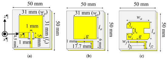
Figure 1.
Geometry of the direct-fed (D-fed) antenna and the proximity-fed (P-fed) antennas. (a) D-fed Rect-MSA; (b) P-fed Rect-MSA; (c) proposed P-fed I-shape MSA.
2.1. Antenna Design and L-Shape Feeding Scheme
The patch antenna of D-fed Rect-MSA and P-fed Rect-MSA is set to 0.253λ0 × 0.253λ0 at 2.45 GHz (wp = wa and lp = la, refer to Figure 1a,b) for comparison purpose. Next, the patch antenna of the proposed P-fed Rect-MSA, which exhibits broad impedance bandwidth, is reduced to become I-shape as shown in Figure 1c. After the size of the antenna is reduced, a drastic increase of the resistance and reactance of the input port of the antenna at 2.45 GHz are observed. Therefore, L-shape feeding scheme is proposed and used to match impedance between P-fed I-shape MSA and feed line. The D-fed Rect-MSA and P-fed I-shape MSA (proposed) are fabricated on 3.2 mm substrate with dielectric constant εr = 3.3, and tan δ = 0.003 for comparison purpose. The resonance frequency from L-shape feed line is estimated, as follows:
Lf is the total inductance from lf1 and lf2 of the L-shape feed line; Cg is the capacitance associated with the coupling gap g shown in Figure 1b,c. The effect of the coupling gap on resonance frequency in Equation (1) will be discussed in simulation results.
The design procedure starts by setting antenna resonance frequency to 2.45 GHz. In Figure 1b,c, the L-shape feed line is proposed and placed in the vicinity of P-fed Rect-MSA to generate two resonance frequencies in order to obtain wide impedance bandwidth. Next, the patch size of P-fed Rect-MSA is reduced to become P-fed I-shape MSA, which is suitable for wearable sensors. To reduce the human body loading effect on the antenna performance, a conductor plate is placed on the bottom of the antenna. The separation gap between the conductor plate and antenna is kept small to realize low profile structure. However, the low profile structure leads to a poor reflection coefficient in the proposed P-fed I-shape MSA backed by the conductor plate. To improve the reflection coefficient, key parameters such as coupling length lf1 and coupling gap g of L-shape proximity feeding scheme are studied to reduce high impedance at the input port.
2.2. Parameter Analysis to Achieve Wideband Response
At the beginning of the antenna design, an identical patch antenna that resonates at 2.45 GHz is chosen for D-fed Rect-MSA and P-fed Rect-MSA. The antennas are then fed by difference feeding techniques for comparison purpose. Figure 2 shows simulated reflection coefficients for D-fed Rect-MSA and P-fed Rect-MSA in the free space. By using the proximity feeding scheme presented in this work, the simulated impedance bandwidth of P-fed Rect-MSA is 1.8 times wider than the one in D-fed Rect-MSA, owning to the dual resonances mode generated by the L-shape feed line and the patch antenna. To obtain a wide impedance bandwidth, the physical length lf1 of the L-shape feed line of P-fed Rect-MSA is optimized to generate lower resonant mode from L-shape feed line at 2.4 GHz.
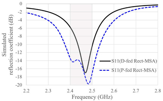
Figure 2.
Simulated reflection coefficient of D-fed (direct-fed) Rect-MSA and P-fed (proximity-fed) Rect-MSA (g = 0.5 mm, la = 27 mm).
After the length la of P-fed Rect-MSA in Figure 1b is reduced from 31 mm (0.253λ0) to 27 mm (0.221λ0), the upper resonant frequency is shifted from 2.45 GHz to 2.72 GHz as illustrated in Figure 3a. Following the length reduction (la) of P-fed Rect-MSA, the upper and lower resonant frequencies fall apart (dashed black line in Figure 3a). Figure 3b also demonstrates shift in upper resonance frequency and drastic increase of Ohmic resistance at 2.45 GHz ISM band after the length la of rectangular P-fed Rect-MSA is reduced (from 31 mm to 27 mm). To overcome the impedance mismatch between the antenna and the L-shape feed line at 2.45 GHz, the center body of P-fed Rect-MSA is truncated to become P-fed I-shape MSA. As a result, the upper resonant frequency is shifted back to 2.45 GHz ISM band and the two resonant frequencies become close to each other again (solid red line showed in Figure 3a). By increasing the length ls of truncated section in P-fed I-shape MSA, Ohmic resistance at the input port is matched to 50 Ω at 2.45 GHz ISM band, as depicted in blue and red lines of Figure 3b. The dual resonances mode with good reflection coefficient is achieved when ls is increased to 5.6 mm. Then, the center frequency of P-fed I-shape MSA is adjusted to 2.45 GHz by truncating upper-left and lower-right corners (lc = 2.4 mm) of the P-fed I-shape MSA.
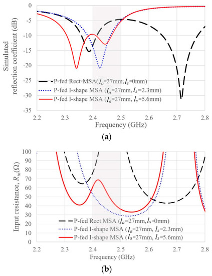
Figure 3.
Length ls is adjusted to bring input resistance of P-fed I-shape MSA close to 50 Ω at 2.45 GHz ISM band, after P-fed Rect-MSA in dashed black line (g = 0.5 mm, la = 31 mm, ls = 0 mm) is miniaturized to become P-fed I-shape MSA (g = 0.5 mm, la = 27 mm, ls varies from 2.3 mm to 5.6 mm). (a) Simulated reflection coefficient; (b) Input resistance Rin.
Figure 4 shows optimization of the coupling gap g between the I-shape patch and the L-shape feed line of P-fed I-shape MSA in order to improve reflection coefficient. A wide impedance bandwidth is realized by adjusting the coupling gap g of the L-shape feed line to reduce inductive reactance at the input port of the proposed antenna. After the coupling gap g is reduced from 0.8 mm to 0.2 mm, inductive reactance is reduced to half of its initial value at 2.45 GHz ISM band as depicted in Figure 4b. As a result, wide impedance bandwidth with reflection coefficient less than 10 dB criterion from 2.36 to 2.48 GHz is obtained in the free space (dashed black line in Figure 4a). From parametric analysis in Figure 2, Figure 3 and Figure 4, the process of obtaining wideband characteristic through L-shape proximity feeding scheme can be summarized, as follows: (1) length ls of truncated section of P-fed I-shape MSA is increased to bring upper and lower resonance frequencies to be close to each other. (2) Coupling gap g is decreased to reduce inductance of the input impedance, so that wide impedance bandwidth with reflection coefficient less than 10 dB criterion could be achieved.
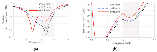
Figure 4.
Input impedance matching in P-fed I-shape MSA through coupling gap g adjustment (refer to Table 2 for dimensions of the antenna). (a) Simulated reflection coefficient; (b) input reactance, Xin.
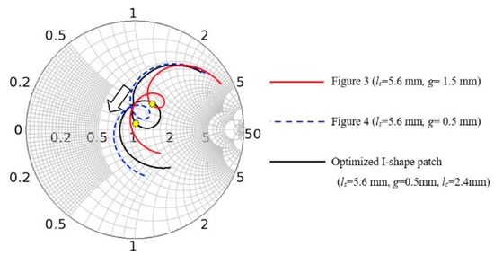
The Smith chart in Figure 5 describes impedance matching of the proposed P-fed I-shape MSA using the L-shape feed line. After the proposed antenna size is reduced, the input impedance of the antenna increases drastically, especially resistance at the input port of the antenna at 2.45 GHz (Figure 3). Next, the coupling gap between the L-shape feed line and the antenna is reduced to 0.5 mm to make the proposed antenna to become less inductive (Figure 4). Finally, two corners of the proposed antenna are truncated to move input impedance at 2.45 GHz closer to circle centered at the coordinate (0, 0) where Z = 50 Ω, as shown by yellow node in the smith chart.
2.3. Conductor Plate in Low Profile Antenna Affixed to Human Body
Figure 6 shows the geometry of P-fed I-shape MSA and simulation setup for antennas affixed to the human body. The proposed antenna is placed on above 200 × 200 mm2 tissue model which consists of skin, fat, and muscle, mimicking human tissue. Table 1 shows dielectric properties obtained from IT’IS Foundation for human tissue model. To reduce backward radiation to the human body, the conductor plate is proposed and placed below the antenna. D-fed Rect-MSA and P-fed I-shape MSA, which are placed in the free space and on human body, are simulated in the following conditions: without the conductor plate, and with the conductor plate. When the 50 × 50 mm2 conductor plate is placed 2 mm below the P-fed I-shape MSA, the antenna has a poor reflection coefficient. The impedance matching technique through the L-shape feed line discussed in Section 2.2 is repeated until the input impedance of the proposed antenna is approximately 50 Ω at 2.45 GHz. Compared with the D-fed Rect-MSA, the proposed P-fed I-shape MSA has more key parameters (coupling gap g, and truncated section of I-shape antenna, ls) to tune for impedance matching.
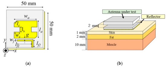
Figure 6.
Geometry of the proposed P-fed I-shape MSA. (a) Proposed antenna after downsizing; (b) simulation setup on the multi-layer tissue model.

Table 1.
Multilayer human tissue model [15].
Figure 7 shows the effect of separation distance between the proposed P-fed I-shape MSA and conductor plate on the gain performance of the antenna. The separation distance is varied from 1 mm to 4 mm, then the gain of antenna in the free space and on human body are observed. Figure 7a shows the simulated gain of the antenna on the multi-layer tissue model (when the separation distance is 4 mm) is above 6 dBi across 2.45 GHz ISM band, which is higher than the gain of the antenna in the free space. Low gain in the free space is due to limited size (50 × 50 mm2) of the ground plane and reflector used. However, the increase of contact area between the human body and reflector enlarges the conductor plate electrically. A separation distance of 2 mm (Figure 7b) is suitable for this work, since the gain difference between the antenna in the free space and on the human body is less than 1 dB at 2.45 GHz ISM band. When the separation distance is reduced further to 1 mm, the human body loading effect reduces the gain of the antenna on the human body (Figure 7c). The gain difference between the antenna on the human body and antenna in the free space is more than 1 dB. For MBAN application, it is recommended to keep the gain of the antenna consistent in the free space and on human tissue. Otherwise, the gain difference corresponds to the working environment, which may raise the demand of the RF power amplifier with auto gain control (AGC) feature for body area network communication. Therefore, the separation distance of 2 mm is chosen in this work to obtain stable gain for the antenna in the free space and on the human body.
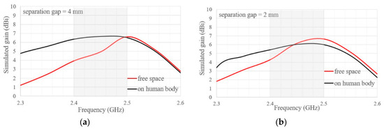
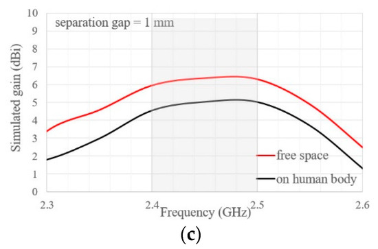
Figure 7.
Effect of separation distance between the proposed P-fed I-shape MSA and conductor plate, simulated in the free space and on the human body; size of the antenna and conductor plate is 50 mm × 50 mm. (a) Separation distance = 4 mm; (b) separation distance = 2 mm; (c) separation distance = 1 mm.
Figure 8 shows the simulated reflection coefficient for the D-fed Rect-MSA and P-fed I-shape MSA in the free space and on the multi-layer tissue model. The operation bandwidth of the proposed P-fed I-shape MSA at 2.45 GHz ISM band is wider than the D-fed Rect-MSA, irrespective of the working environment. The D-fed Rect-MSA suffered a 30 MHz frequency shift after the antenna is moved from the free space to the human body. It is worth mentioning that the proposed P-fed I-shape MSA exhibits reflection coefficient less sensitive to human body loading effect. The resonance frequency of the proposed P-fed I-shape MSA experiences only 10 MHz frequency shift at upper frequency. It is worth noting that the reactance component of the proposed L-shape feed line is more robust to the change in the working environment from the free space to the human body, which satisfies the requirements of MBAN applications.
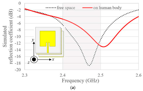
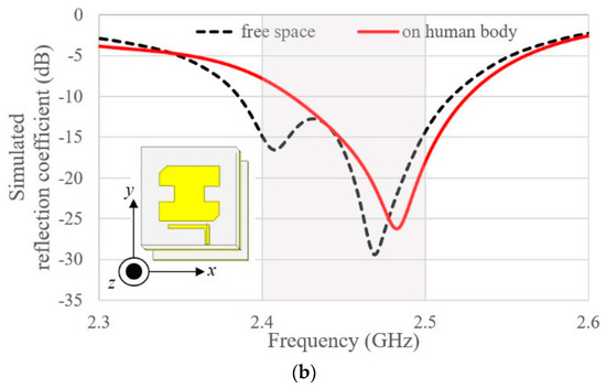
Figure 8.
Shift in resonance frequency due to human body loading effect. (a) D-fed Rect-MSA; (b) proposed P-fed I-shape MSA (refer to Table 2 for the dimensions of the related antennas).
Figure 9a shows the influence of the conductor plate’s size on the gain response of the proposed antenna in the free space. As can be seen, the conductor plate acts as a reflector for P-fed I-shape at certain frequencies, start from2.45 GHz to 2.5 GHz. The size of the conductor plate determines front-to-back (F/B) lobe ratio, where the antenna backed by larger conductor plate has higher gain than the one backed by 50 × 50 mm2 conductor plate (Figure 9a). Since this work focuses on the compact antenna design, the 50 × 50 mm2 (0.4λ0 × 0.4λ0) conductor plate is selected because it has stable gain at center frequency (2.45 GHz) for the antenna in the free space and on human body. Figure 9b shows the contribution of the conductor plate on the gain of P-fed I-shape MSA when it is placed on human body and simulated as follows: (1) P-fed I-shape MSA with conductor plate; (2) P-fed I-shape MSA without conductor plate. For the P-fed I-shape MSA without the conductor plate, gain degradation exceeds 1.5 dB due to human body loading effect, while the gain of the P-fed I-shape MSA backed by the conductor plate is slightly affected. Additionally, gain variation in P-fed I-shape MSA backed by the conductor plate when the working environment is changed (from the free space to the human body) is less than 1 dB from 2.42 GHz to 2.5 GHz.
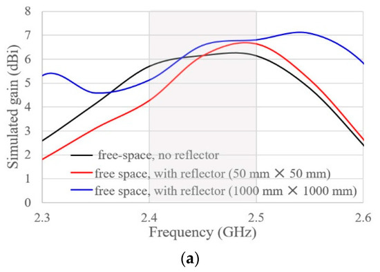
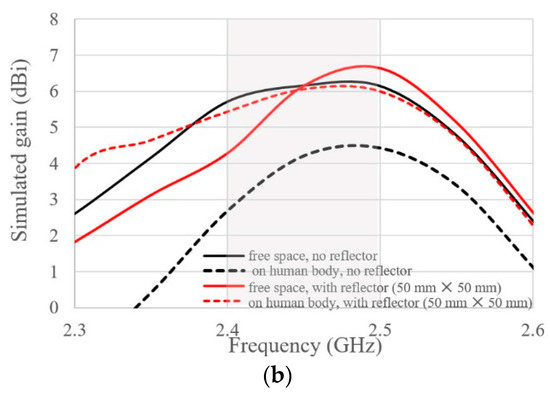
Figure 9.
Influence of the conductor plate size on the gain of the proposed antenna (refer to Table 2 for dimensions of the proposed antenna). (a) P-fed I-shape MSA in the free space only; (b) P-fed I-shape MSA in the free space and on the human body.
Figure 10a shows the radiation efficient of the proposed P-fed I-shape MSA and D-fed Rect-MSA in the free space. Across the 2.45 GHz ISM band, the proposed P-fed I-shape MSA and D-fed Rect-MSA have radiation efficiency over 90%. As for the D-fed Rect-MSA, radiation efficiency starts to decrease when operating frequency is located below or above the center frequency (2.46 GHz). Loss due to impedance mismatch in the direct microstrip feed line of D-fed Rect-MSA limits beamwidth of the antenna. Figure 10b shows radiation efficiency of the proposed P-fed I-shape MSA and D-fed Rect-MSA when the antennas are affixed to the human body. Compared with the D-fed Rect-MSA, the radiation efficiency of the proposed P-fed I-shape MSA is less affected by human body loading. Although decrease in radiation efficiency of the P-fed I-shape MSA affixed to human body is observed, the antenna’s radiation efficiency exceeds 80% from 2.44 GHz to 2.54 GHz.
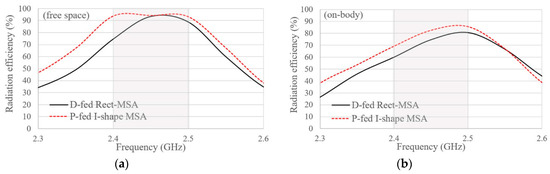
Figure 10.
Radiation efficient of P-fed I-shape MSA and D-fed Rect-MSA backed by conductor plate. (a) Antennas in the free space; (b) antennas on the human body.
Figure 11 shows simulated 3D radiation patterns for the P-fed I-shape MSA backed by conductor plate in the free space and on the human body at 2.45 GHz, in Figure 11a,b respectively. The back lobe level decreases when the operating environment is changed from the free space to human body. For the antenna affixed onto the human body, the area of contact between the conductor plate of the P-fed I-shape MSA increases, thus the conductor plate becomes electrically large to suppress backward radiation. The gain scale in Figure 11 shows gain of the antenna on the human body remains at 6.2 dBi regardless of the operating environment, however, the back lobe level is suppressed when the antenna is moved from the free space (Figure 11a) to the human body (Figure 11b). Next, the specific absorption rate is used to calculate average radiated power absorbed by human tissue due to electromagnetic (EM) leakage from the proposed antenna.
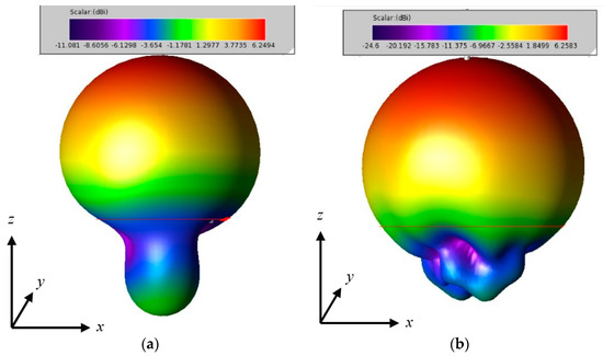
Figure 11.
3D radiation patterns of the P-fed I-shape MSA backed by conductor plate at 2.45 GHz in xz-plane. (a) Antenna in the free space; (b) antennas on the human body.
2.4. Specific Absorption Rate (SAR)
Amount of EM energy absorbed by the human body could be measured through specific absorption rate (SAR). According to FCC regulations [16] and IEEE C95.1 [17], EM energy absorbed by the human body should not exceed 1.6 W/kg averaged over 1 g of tissue. Figure 12 shows the SAR simulation setup for the proposed antenna (backed by conductor plate) placed on multi-layer tissue. For SAR evaluation, an identical simulation environment is used to evaluate SAR for D-fed Rect-MSA and the proposed P-fed I-shape MSA, i.e., 50 × 50 mm2 conductor plate size is used. It is worthy to mention that the maximum SAR in the P-fed I-shape MSA is 0.6414 W/kg, which is lower than SAR = 1.524 W/kg in D-fed Rect-MSA when the incident power density at the antenna surface is 100 mW/cm2 (based on FCC-regulated maximum power density). Low SAR in the proposed P-fed I-shape MSA is in agreement with simulation results in Figure 11b, which shows that the back lobe is suppressed when the P-fed I-shape MSA backed by the conductor plate is moved from the free space to the human body. Next, the P-fed I-shape MSA and D-fed Rect-MSA are fabricated, measured, and compared to verify the robustness of the antennas against human body loading effect.
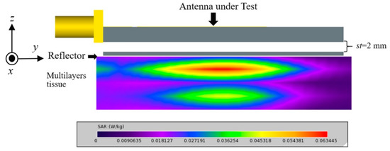
Figure 12.
Specific absorption rate (SAR) simulation setup to calculate electromagnetic energy absorbed by human tissue.
3. Fabrications
The proposed P-fed I-shape MSA and D-fed Rect-MSA were fabricated for comparison purpose. The antennas were fabricated on polyphenylene ether (PPE) substrate (inset of Figure 13). Styrofoam is then inserted as a spacer between antennas (substrate thickness ta = 3.2 mm) and conductor plates (substrate thickness tr = 0.8mm). The total antenna height, including the conductor plate and styrofoam (st = 2 mm), is 6 mm. The final dimensions of the P-fed I-shape MSA are listed in Table 2. SMA RF connectors were mounted on the rear side of the antennas to ensure that the conductor plate on the bottom of the P-fed I-shape MSA and D-fed Rect-MSA is in contact with the human body.
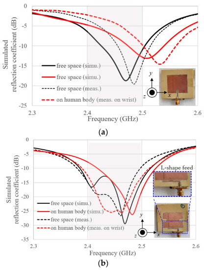
Figure 13.
Simulated and measured reflection coefficient of the antenna in the free space and on human body. (a) D-fed Rect-MSA; (b) P-fed I-shape MSA.
Table 2.
Dimension of the proposed P-fed I-shape MSA of Figure 6 (units in mm).
4. Experimental Results
The proposed antenna (P-fed I-shape MSA) is compared with D-fed Rect-MSA for the antenna in the free space and on the human body. Keysight 8719D vector network analyzer (50 MHz to 13.5 GHz) was used to measure reflection coefficients of the antennas in the free space and on human body. To investigate the human body loading effect, the proposed antenna was affixed on different parts of the human body by using adhesive tape. Radiation patterns and antenna gain were measured and validated in the anechoic chamber. Horn antenna (Microwave Factory MDH0118) was used as pre-calibrated standard gain antenna to measure the radiation patterns of the proposed antenna. The gain of the proposed antenna is measured and calculated by using the gain comparison method.
4.1. Human Body Loading Effect on the Antenna Reflection Coefficient
Figure 13 shows the reflection coefficients of the proposed P-fed I-shape MSA and D-fed Rect-MSA in the free space and on the human body. As can be seen in the figure, measured reflection coefficients of the antennas in the free space and on the human body are agreed with simulation ones. Comparison of Figure 13a with Figure 13b demonstrates that, in the presence of the human body, the L-shape proximity feeding scheme introduced in this work is more robust to the change of working environment, compared with direct feeding scheme in D-fed Rect-MSA. In simulation results, lower resonance frequency of P-fed I-shape MSA disappears when the antenna is affixed onto human tissue model. Contrarily, the measurement result shows lower resonance frequency and is not affected when the antenna is affixed to the wrist. The disagreement in the lower resonance frequency between simulation and measurement happens because the area of the wrist exposed to the electromagnetic wave is smaller than than in the human tissue model (200 mm × 200 mm) used in the simulation. To further verify the measured result, extra measurements on the reflection coefficients of the antenna were made on different parts of human body.
Figure 14 shows the measured reflection coefficient of the P-fed I-shape MSA affixed to various positions on the human body. It can be observed that measured reflection coefficient is insensitive to being situated in close proximity to the human body. Reflection coefficient is only slightly affected when the antenna is moved from wrist to the upper arm and chest. The proposed antenna has impedance bandwidth (satisfies reflection coefficient less than 10-dB criterion) of 120 MHz at 2.45 GHz ISM band, which is wider than D-fed Rect-MSA.
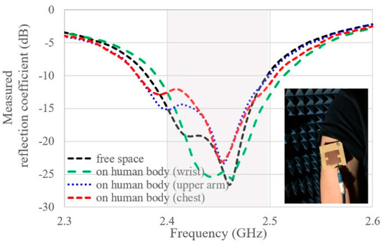
Figure 14.
Measured reflection coefficient of the proposed I-shape MSA on difference parts of the human body.
4.2. Radiation Patterns and Measured Gain
Figure 15 and Figure 16 shows normalized radiation patterns for the proposed P-fed I-shape MSA at xz plane (φ = 0°) and yz plane (φ = 90°) at 2.45 GHz. In Figure 15 and Figure 16, all dataset in xz plane (co-polarized Eφ) and yz plane (co-polarized Eθ) are divided by the peak gain at their respective planes. Next, the normalized gain is plotted starting from the maximum value of 0 dB. Figure 15a,b shows, for the case of antenna in the free space, the measured radiation patterns coincidence with the simulated ones at broadside scenario along the positive z-axis. Simulated gain is 6.2 dBi and the measured gain is 5.09 dBi at 2.45 GHz along z-axis. Measured radiation patterns in both planes (xz-plane and yz-plane) are agreed with the simulations results for the antenna placed in the free space. By considering the reliability of the simulation results, broadside radiation patterns coincident to the simulation results are expected for the antenna affixed to the human body.
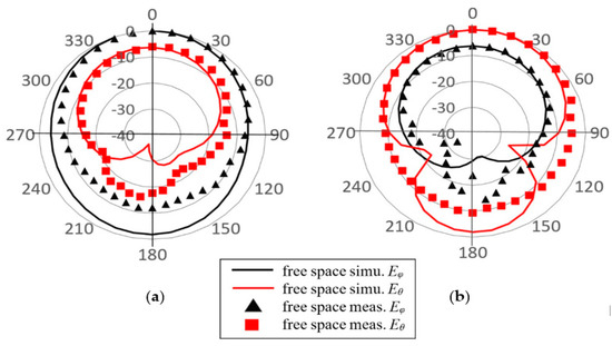
Figure 15.
Simulated and measured radiation patterns of P-fed I-shape MSA at 2.45 GHz for antenna used in off-body communication. (a) xz-plane; (b) yz-plane.
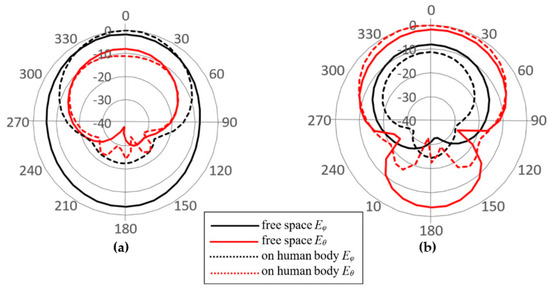
Figure 16.
Radiation patterns of P-fed I-shape MSA at 2.45 GHz for antenna in the free space (solid) and on human body (dashed). (a) xz plane; (b) yz plane.
Figure 16 shows the dominant electric fields in the observation planes (Eφ in xz plane, Eθ in yz plane) for the antenna in the free space and on the human body. The proposed P-fed I-shape MSA has stable antenna gain at broadside, even when the antenna is being situated on the human body. The radiation pattern of the antenna on the human body is unidirectional, which is similar to radiation pattern of the antenna in the free space. The Eφ and Eθ components of the P-fed I-shape MSA in free space are slightly lower than the one affixed to the human body, due to the high back lobe of the antenna placed in the free space, which has a limited area of conductor plate (50 × 50 mm2). When the proposed antenna is affixed to the human body, the contact area between the conductor plate and the human body becomes electrically large, therefore the back lobe level is suppressed.
Table 3 shows comparisons of the proposed antenna with other state-of-art antennas for the body area network. There are distinct differences between unidirectional antennas and omnidirectional UWB antennas in terms of gain characteristic and impedance bandwidth, therefore antennas with unidirectional characteristics are selected for comparison. As can be seen in the table, the proposed antenna has an operation bandwidth almost the same as EBG-backed antenna. Wide impedance bandwidth is achieved in the work, owing to extra resonance from L-fed feed line. For low profile antennas discussed, the size of conductor plate in the proposed work is slightly smaller than a metasurface that consists of periodic structure [7,8]. Gain difference between the proposed antenna in the free space and on the human body is less than 1 dB across 2.45 GHz ISM band. Air gap of 2 mm (0.016λ0) in the proposed antenna is smaller than air gap in EBG-backed antennas in [7,8]. Regardless of the operating environment, gain of the proposed antenna has a stable radiation pattern which makes its suitable to be deployed on the human body and remote terminals.
Table 3.
Performance comparison with other state-of-art wearable antennas.
5. Conclusions
A compact microstrip patch antenna backed by a conductor plane has been presented. The conductor plate functions as reflector, and is placed below the antenna to suppress EM radiation to the human body. The proposed antenna with the L-shape proximity feeding scheme generates a dual-resonances mode for a wide impedance bandwidth. Additionally, the proposed feeding scheme offers more parameters for impedance matching in order to realize low profile antenna. A prototype was designed, fabricated, and compared with the conventional direct-fed patch antenna. Measured reflection coefficient and radiation characteristics of the proposed antenna agree well with the simulation results, which shows wide impedance bandwidth at 2.45 GHz ISM band for antenna working in the free space and on the human body. The calculated SAR value below FCC limitation demonstrates that the proposed antenna is suitable for smart MBAN applications. For future works on the body-centric antenna, study on the reflection phase corresponds to the separation distance between the antenna and conductor plate is required to find achievable maximum gain. Additionally, fabrication of a phantom mimicking the characteristic of human tissue is required for radiation pattern measurement of the body-centric antenna affixed to the human body.
Author Contributions
This article is contributed by 2 authors; their individual contributions are listed out, as follows: Conceptualization, C.-E.G. and T.F.; methodology, C.-E.G. and T.F.; software, C.-E.G.; validation, C.-E.G.; formal analysis, C.-E.G.; investigation, C.-E.G. and T.F.; resources, C.-E.G.; data curation, C.-E.G. and T.F.; writing—original draft preparation, C.-E.G.; writing—review and editing, C.-E.G. and T.F.; visualization, C.-E.G.; supervision, T.F.; project administration, C.-E.G. and T.F.; funding acquisition, C.-E.G. All authors have read and agreed to the published version of the manuscript.
Funding
This work was supported in part by a Grants-in-Aid for Research Activity Start-up under grant number 19K21080 from Japan Society for the Promotion of Science (JSPS).
Conflicts of Interest
This work is an original work and it is not published or under consideration for publication elsewhere.
References
- Yan, S.; Soh, P.-J.; Vandenbosch, G.A.E. Wearable Ultrawideband Technology—A Review of Ultrawideband Antennas, Propagation Channels, and Applications in Wireless Body Area Networks. IEEE Access 2018, 6, 42177–42185. [Google Scholar] [CrossRef]
- Alomainy, A.; Sani, A.; Rahman, A.; Santas, J.G.; Hao, Y. Transient Characteristics of Wearable Antennas and Radio Propagation Channels for Ultrawideband Body-Centric Wireless Communications. IEEE Trans. Antennas Propag. 2009, 57, 875–884. [Google Scholar] [CrossRef]
- Chandra, R.; Johansson, A.J. A Link Loss Model for the On-Body Propagation Channel for Binaural Hearing Aids. IEEE Trans. Antennas Propag. 2013, 61, 6180–6190. [Google Scholar] [CrossRef]
- Wang, D.; Evans, D.; Krasinski, R. IEEE 802.15.4J: Extend IEEE 802.15.4 radio into the MBAN spectrum [Industry Perspectives]. IEEE Wirel. Commun. 2012, 19, 4–5. [Google Scholar] [CrossRef]
- Hall, P.S.; Hao, Y.; Nechayev, Y.I.; Alomainy, A.; Constantinou, C.; Parini, C.; Kamarudin, M.R.; Salim, T.Z.; Hee, D.T.M.; Dubrovka, R.; et al. Antennas and propagation for on-body communication systems. IEEE Antennas Propag. Mag. 2007, 49, 41–58. [Google Scholar] [CrossRef]
- Lin, C.; Saito, K.; Takahashi, M.; Ito, K. A Compact Planar Inverted-F Antenna for 2.45 GHz On-Body Communications. IEEE Trans. Antennas Propag. 2012, 60, 4422–4426. [Google Scholar] [CrossRef]
- Gao, G.; Hu, N.; Wang, S.; Yang, C. Wearable planar inverted-F antenna with stable characteristic and low specific absorption rate. Microw. Opt. Technol. Lett. 2018, 60, 876–882. [Google Scholar] [CrossRef]
- Abbasi, M.A.B.; Nikolaou, S.S.; Antoniades, M.A.; Stevanović, M.N.; Vryonides, P. Compact EBG-Backed Planar Monopole for BAN Wearable Applications. IEEE Trans. Antennas Propag. 2017, 65, 453–463. [Google Scholar] [CrossRef]
- Tong, X.; Liu, C.; Liu, X.; Guo, H.; Yang, X. Switchable ON-/OFF-Body Antenna for 2.45 GHz WBAN applications. IEEE Trans. Antennas Propag. 2018, 66, 967–971. [Google Scholar] [CrossRef]
- Mendes, C.; Peixeiro, C. A Dual-Mode Single-Band Wearable Microstrip Antenna for Body Area Networks. IEEE Antennas Wirel. Propag. Lett. 2017, 16, 3055–3058. [Google Scholar] [CrossRef]
- Yang, D.; Hu, J.; Liu, S. A Low-Profile UWB Antenna for WBAN Applications. IEEE Access 2018, 6, 25214–25219. [Google Scholar] [CrossRef]
- Zhu, X.Q.; Guo, Y.X.; Wu, W. Miniaturized Dual-Band and Dual-Polarized Antenna for MBAN Applications. IEEE Trans. Antennas Propag. 2016, 64, 2805–2814. [Google Scholar] [CrossRef]
- Chandran, A.R.; Timmons, N.; Morrison, J. Stacked circular patch antenna for medical BAN. In Proceedings of the 2014 Loughborough Antennas and Propagation Conference (LAPC), Loughborough, UK, 10–11 November 2014; pp. 22–25. [Google Scholar]
- Fan, Y.; Yahya, R.S. Reflection Phase Characterizations of the EBG Ground Plane for Low Profile Wire Antenna Applications. IEEE Trans. Antennas Propag. 2003, 51, 2691–2703. [Google Scholar]
- Dielectric Properties of Tissues. Available online: https://itis.swiss/virtual-population/tissue-properties/database/dielectric-properties/ (accessed on 24 September 2019).
- Means, D.L.; Chan, K.W. Evaluating Compliance with FCC Guidelines for Human Exposure to Radiofrequency Electromagnetic Fields; Federal Communications Commission Office of Engineering, and Technology: Washington, DC, USA, 2001.
- IEEE Standard for Safety Levels with Respect to Human Exposure to Radio Frequency Electromagnetic Fields 3 kHz to 300 GHz; IEEE Standard C95.1-2005; IEEE: Piscataway, NJ, USA, 2005.
© 2019 by the authors. Licensee MDPI, Basel, Switzerland. This article is an open access article distributed under the terms and conditions of the Creative Commons Attribution (CC BY) license (http://creativecommons.org/licenses/by/4.0/).