1. Introduction
With the high requirement for high data rates and large channel capacity, the expectations for modern wireless communication systems are ratcheted up. The fifth generation (5G) communication is considered a prospective option to meet the demand for explosive growth of data rate and super high channel capacity, which is developing rapidly [
1,
2]. However, limited spectral resources will be a bottleneck in the development of modern wireless communication in the near future. As we all know, the Multiple Input Multiple Output (MIMO) technique can obviously increase channel capacity [
3] without occupying additional bandwidth. On the view of MIMO antenna, channel capacity can be highly improved by increasing the quantity of antennas at the receiver and transmitter in MIMO systems. However, more antenna elements and closer distances between elements will cause a more intense mutual coupling, which may decrease the performance of the MIMO system. To solve this problem, some MIMO antenna designs with diverse decoupling methods have been investigated, which can be classified into three categories. The first one introduces decoupling structures to improve isolation, which includes neutralization lines [
4,
5], defected ground structures [
6,
7], decoupling networks [
8,
9], etc. The second category applies a diversity technique to improve isolation; it includes spatial, polarization, and pattern diversity. The last one is a combination of the two methods mentioned above, which can be used widely to further improve the isolation.
By utilizing decoupling structures, significant isolation improvement can be obtained. However, the introduction of decoupling structures will make the MIMO antenna system complex. Meanwhile, a certain space between antenna elements is needed to add the decoupling structures, which limits the miniaturization design of the MIMO antenna systems. For example, an eight-element UWB-MIMO antenna array is reported in [
10]. The isolation of 20 dB is achieved by using three distinct isolation mechanisms, including a closed-loop frequency selective surface (CL-FSS), defected ground planes, and decoupling structure of quad strip-connected circular arc. However, their relatively large size makes the multi-element MIMO antenna bulky. In [
11], inversed I-shape slots and neutralization line (NL) are used to improve the isolation of an eight-element MIMO antenna array. Although neutralization line is a simple method to cancel the original coupling, ingenious design is required. The author of [
12] describes the design of a novel planar MIMO antenna, in which coupling parasitic elements are incorporated to enhance isolation. However, mutual couplings between ports exhibit isolation of only 10 dB, and the number of MIMO antenna can only be even.
Diversity techniques are also commonly used to enhance isolation in MIMO antenna systems. Spatial diversity, as one of the techniques, is easy to perform, but larger spacing is needed between elements. For example, spatial diversity is utilized for a 10-element MIMO antenna array in [
13]; the isolation of more than 10 dB is obtained over 3.4–3.8 GHz, but the distance between antennas is larger than 0.23λ
0. Polarization diversity is also an effective way to improve the isolation between antenna elements. Two different four-antenna array types placed symmetrically are used to form an eight-element MIMO antenna in [
14]. Orthogonal polarization is adopted to improve isolations between two antenna array types, but the isolation is only about 12.5 dB over 2.5–2.6 GHz, and the distance between two different four-antenna array types is about 0.12λ. A compact eight-element MIMO antenna for a 5G mobile terminal is investigated in [
15]. The elements are placed symmetrically, and pattern diversity is utilized to improve the isolation, but the isolation is just 10 dB and the spacing between the elements is larger than 14 mm.
The method of combining decoupling structure with diversity techniques to improve the isolation has also been studied. As investigated in [
16,
17], the parasitic element and neutralization lines are incorporated with pattern diversity, and isolations of 10 and 15 dB are increased, respectively. But combination of the decoupling structures and pattern diversity lead to a complex design, and the MIMO antenna system is not extensible.
In a word, decoupling structures usually require a certain space between antenna elements, which limits the miniaturization of the antenna and increases the complexity of the MIMO systems. In addition, diversity techniques (such as polarization diversity, etc.) generally have special requirements for antenna design and arrangement, which also limits the expansibility of MIMO antenna for more application. In order to solve these problems, a planar flexibly extensible MIMO antenna array is proposed in this paper. The proposed MIMO antenna array allows extension in a number of elements, which can meet the demands of future communications requiring multiple antennas. Meanwhile, the proposed MIMO antenna exhibits high isolation without utilizing any extra decoupling structures, and antenna elements are placed next to each other with a spacing of 0 mm. The absence of a decoupling structure and spacing of 0 mm between elements help in achieving a compact MIMO antenna configuration and reducing the complexity of the MIMO systems. To the best of the authors’ knowledge, there is no report on a planar flexibly extensible MIMO antenna with a self-isolation property, which allows flexible extension in a number of elements, linear arrangements of elements with spacing of 0 mm, and the absence of decoupling structure between elements.
Taking an eight-element MIMO antenna array as a test example, fabrication and test was carried out. Eight identical elements were arranged adjacent to each other with a spacing of 0 mm in one row, which is different from the orthogonal placement in previous MIMO antenna designs. The antenna element contains a split loop monopole and a central slotted ground loaded with two reversed L-shape strips. Two inverted-L shaped strips are used not only as the isolating element but also as radiating elements. The fundamental properties of the proposed eight-element MIMO antenna array in terms of S parameters, radiation pattern, efficiency, ECC, and total active reflection coefficient (TARC) have been investigated in the following sections.
2. Antenna Element Design
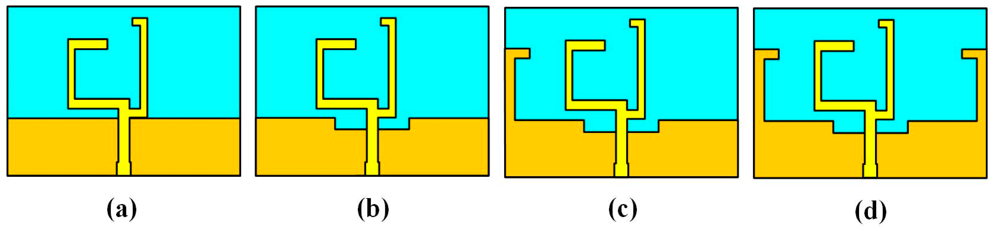
The proposed antenna element contains a split ring monopole and a central slotted ground with two inverted L-shape strips, which evolved from a simple split ring monopole antenna; evolution of the design process is depicted in
Figure 1. The single antenna is designed on the substrate of Teflon with loss tangent 0.02 and relative permittivity 2.65. The deep yellow areas in
Figure 1 denote the ground printed on the back of the substrate, while pale yellow areas indicate the split ring monopole printed on the top of the substrate. A brief description of the stepwise modification is as follows: (1) The original simple monopole antenna denoted by reference antenna A is shown in
Figure 1a; (2) a slot is etched in the middle of the ground, namely reference antenna B; (3) an inversed L-shape strip is loaded on the left side of the ground on the basis of reference antenna B, which is represented by reference antenna C; (4) the proposed single-element antenna is obtained by loading an inversed L-shape strip on the right side of the ground on the basis of reference antenna C. The proposed single-element antenna is simulated and optimized by using electromagnetism simulation software, and the optimized value of the geometric parameters for the single-element antenna illustrated in Figure 3 are listed in
Table 1.
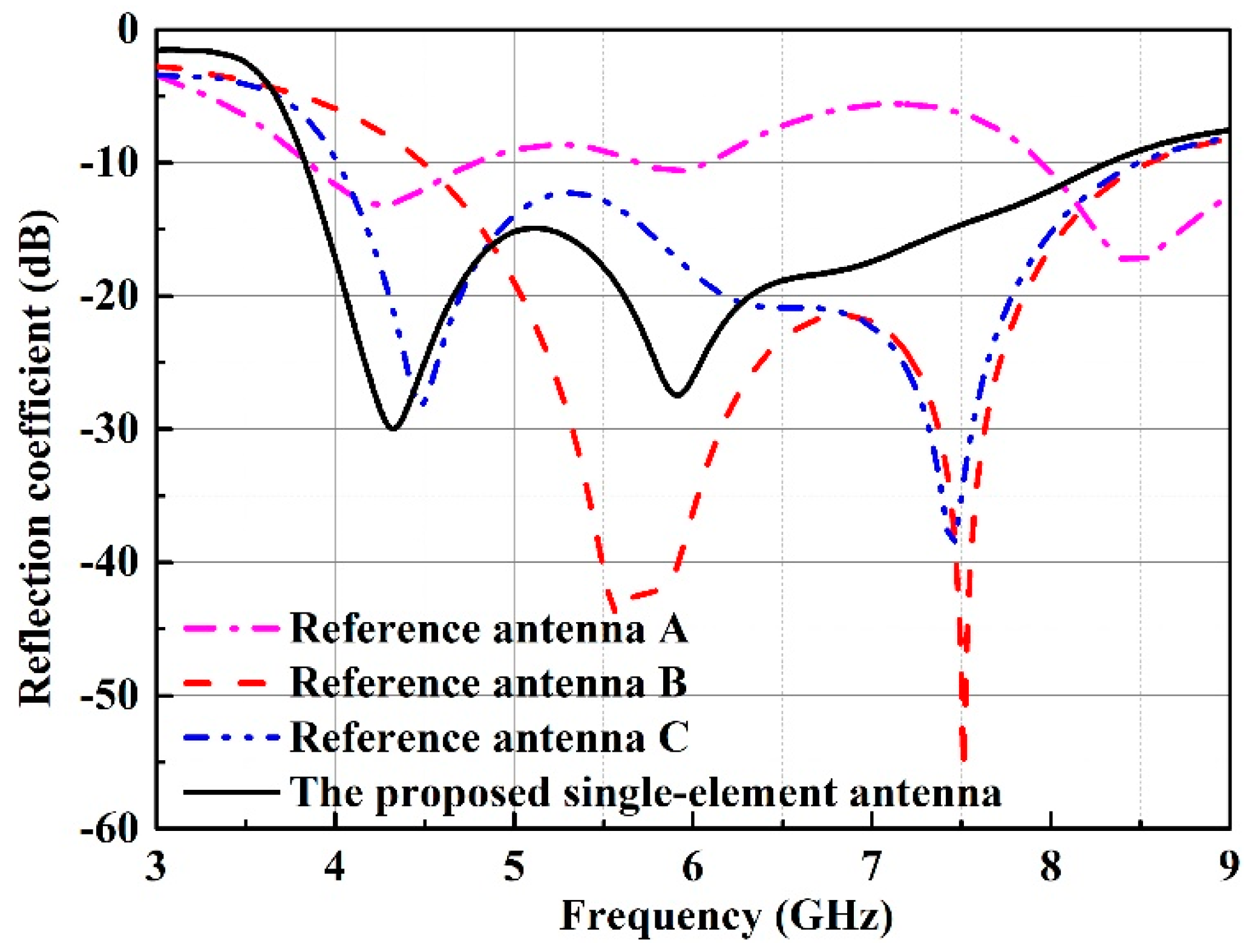
Figure 2 displays the simulated reflection coefficients of reference antenna A, B, C and the proposed single-element antenna. It can be seen that reference antenna A has two narrow working bands. The lower and higher working bands of reference antenna B are produced by etching a slot in the middle of the ground, and then impedance bandwidth (IBW) is broadened. For reference antenna C, the bandwidth is further widened by loading the inversed L-shape strip on the left side of the ground. Compared to the reference antenna C, the higher resonance of the proposed single-element antenna shifts to the lower frequency, while the bandwidths of both antennas are close to each other. However, it should be noted that the main difference between reference antenna C and the proposed single-element antenna is that the latter can be used to form an extensible MIMO antenna array. From
Figure 2, we can conclude that the single-element antenna can achieve wide impedance bandwidth (IBW) of 74% (3.83–8.32 GHz).
3. Eight-Element MIMO Antenna Design
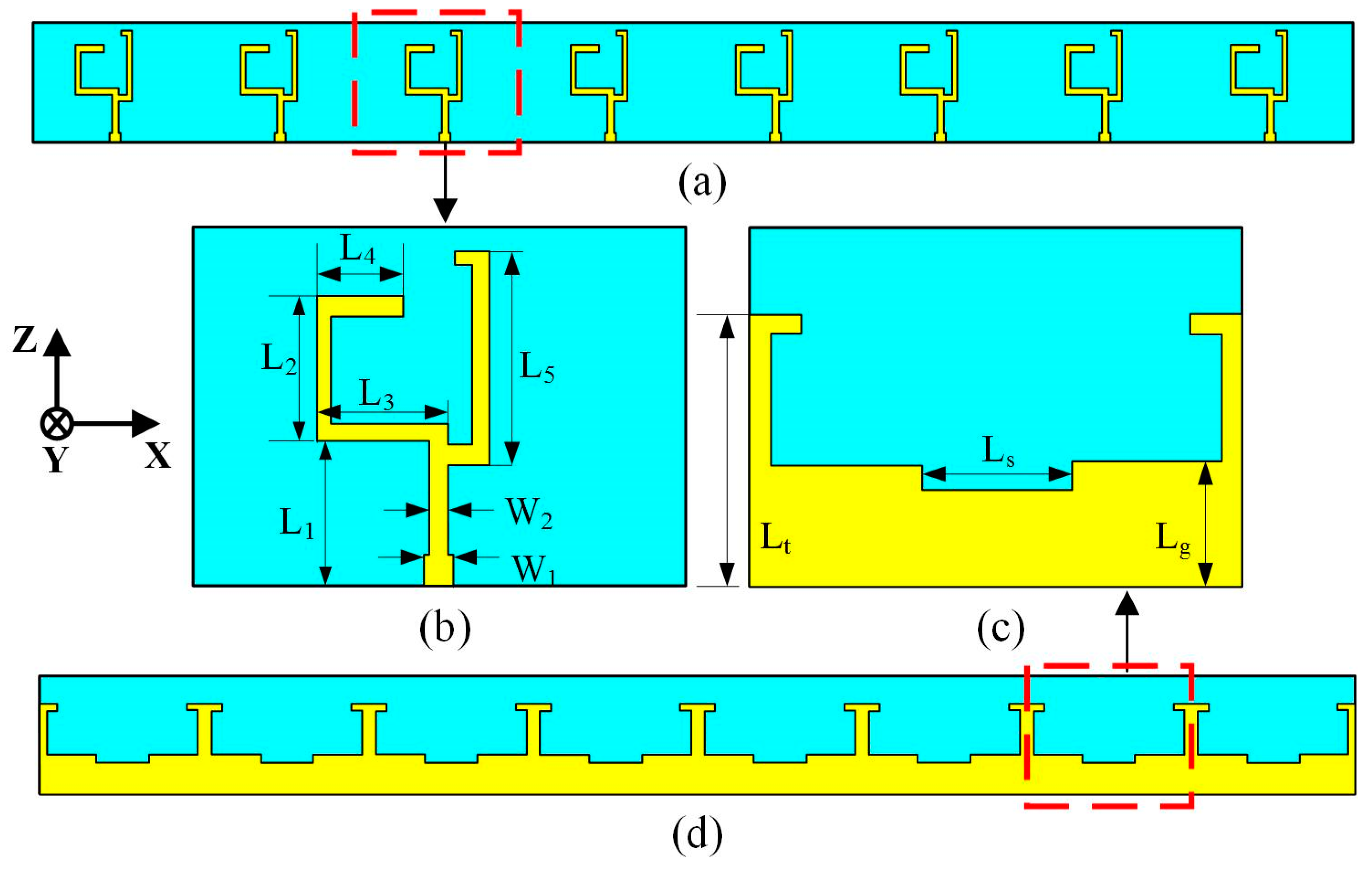
In order to increase channel capacity and data rate, a multi-element MIMO antenna array is needed in MIMO systems. In this section, based on the single-element MIMO antenna designed in
Section 2, an eight-element MIMO antenna array is formed by placing eight identical elements adjacent to each other in one row with spacing of 0 mm. In addition, no extra decoupling element is loaded between any adjacent element. The substrate of Teflon is utilized to fabricate the circuit board of the eight-element antenna array, which is the same as the one used in a single-element antenna. Front and bottom views of the eight-element MIMO antenna array are displayed in
Figure 3, in which the geometry of the antenna element is illustrated.
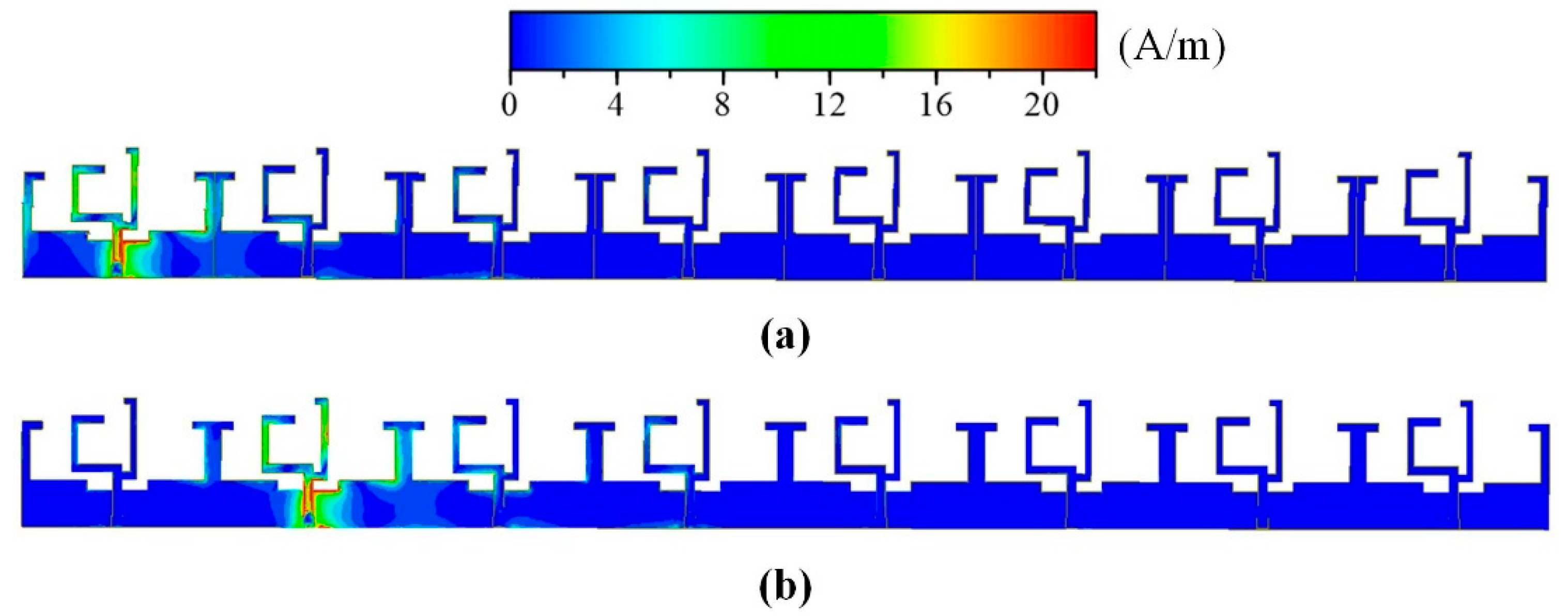
Owing to the reversed L-shape strips on the ground, high isolation can be realized. In order to verify the isolation effect, a current distribution analysis on the eight-element MIMO antenna array is conducted.
Figure 4 shows the surface current distributions at 4.5 GHz, in which Element 1 and 2 are excited, respectively. When port 1 is excited, the other ports are connected with matching loads, and a large part of the surface current is bounded around reversed L-shape strips. Likewise, when port 2 is excited, a great majority of the surface current is confined to the inverted L-shape strips. It can be concluded that the reversed L-shape strips can significantly ameliorate isolation between the elements.
4. Results and Discussion
To further validate the performance of the eight-element MIMO antenna array, the simulated and measured results are discussed as follows: the simulation results of S parameters are firstly verified by test results, followed by an analysis of the radiation pattern and efficiency.
The envelope correlation coefficient (ECC), which is calculated by the test results, is then presented to assess the diversity performance of the eight-element MIMO antenna array. Finally, the TARC is calculated to properly characterize the bandwidth of the MIMO antenna system.
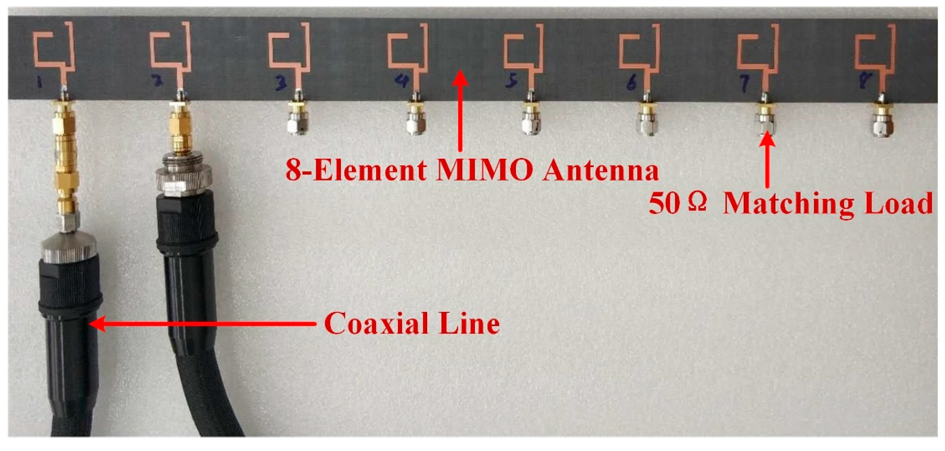
An eight-element antenna prototype is thus manufactured and a photograph of the same is shown in
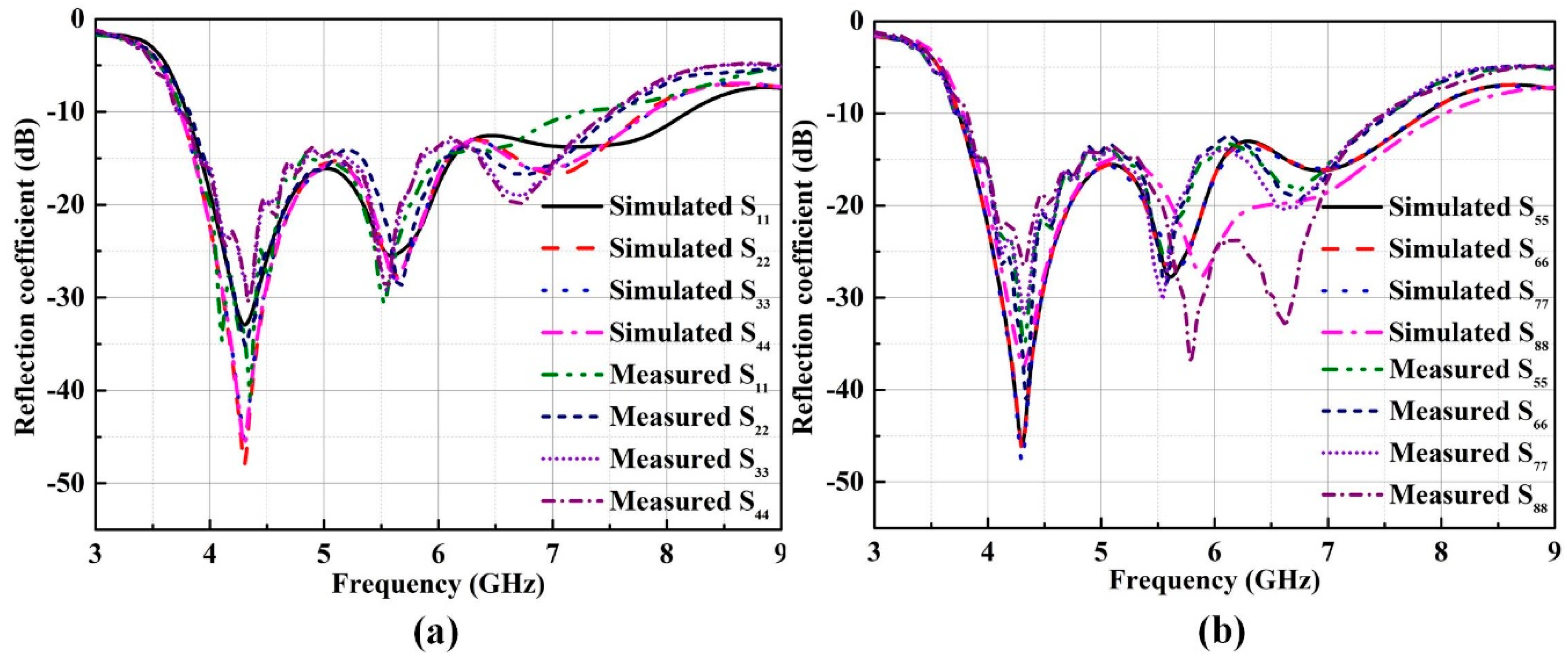
Figure 5. The simulated results of S-parameters are obtained based on electromagnetism simulation software, which are validated by test results measured by the E8361 Agilent network analyzer. In the process of measurement, two ports of the eight-element MIMO antenna are connected to the Agilent network analyzer, while the other ports are terminated with 50 Ω matching loads. The simulation reflection coefficients match well with the measured ones, which is displayed in
Figure 6. Small discrepancies observed may come from fabrication errors and deviation of dielectric constant. It can be seen from the measured reflection coefficients that the -10dB impedance bandwidths (IBWs) of the eight antennas cover a wide band of 3.76–7.25 GHz, which can cover the operating band of 5G communication.
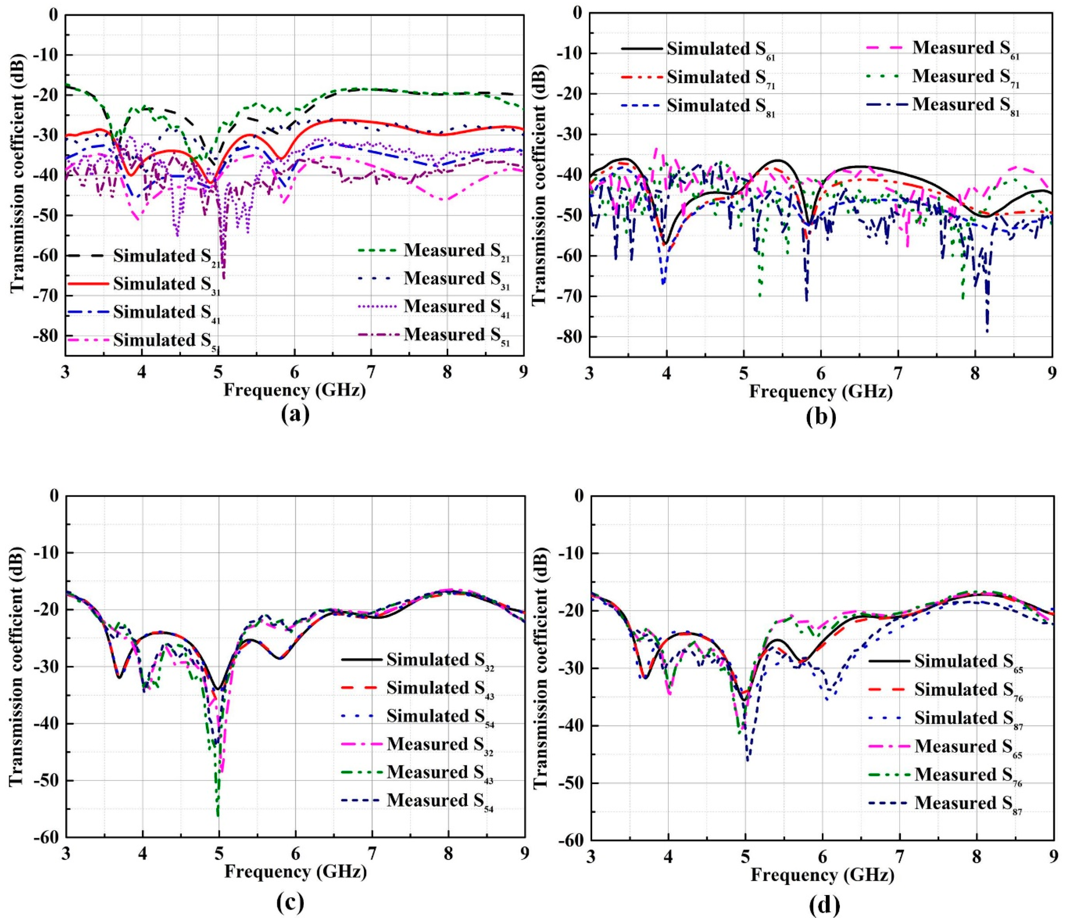
The simulated transmission coefficients between antenna elements agree well with the experimental ones, which are displayed in
Figure 7. Because isolations between nonadjacent elements are significantly higher than 20 dB across the whole working band of 3.76–7.25 GHz, only the isolations between element 1 and other elements as well as isolations between remaining adjacent antenna elements are plotted. The low transmission coefficients between elements imply a good isolation characteristic. From
Figure 7, we can see that the isolations between adjacent elements are higher than 18 dB across the whole working band, while the isolations are better than 22 dB within bands of the concerned sub-6 GHz for 5G communications.
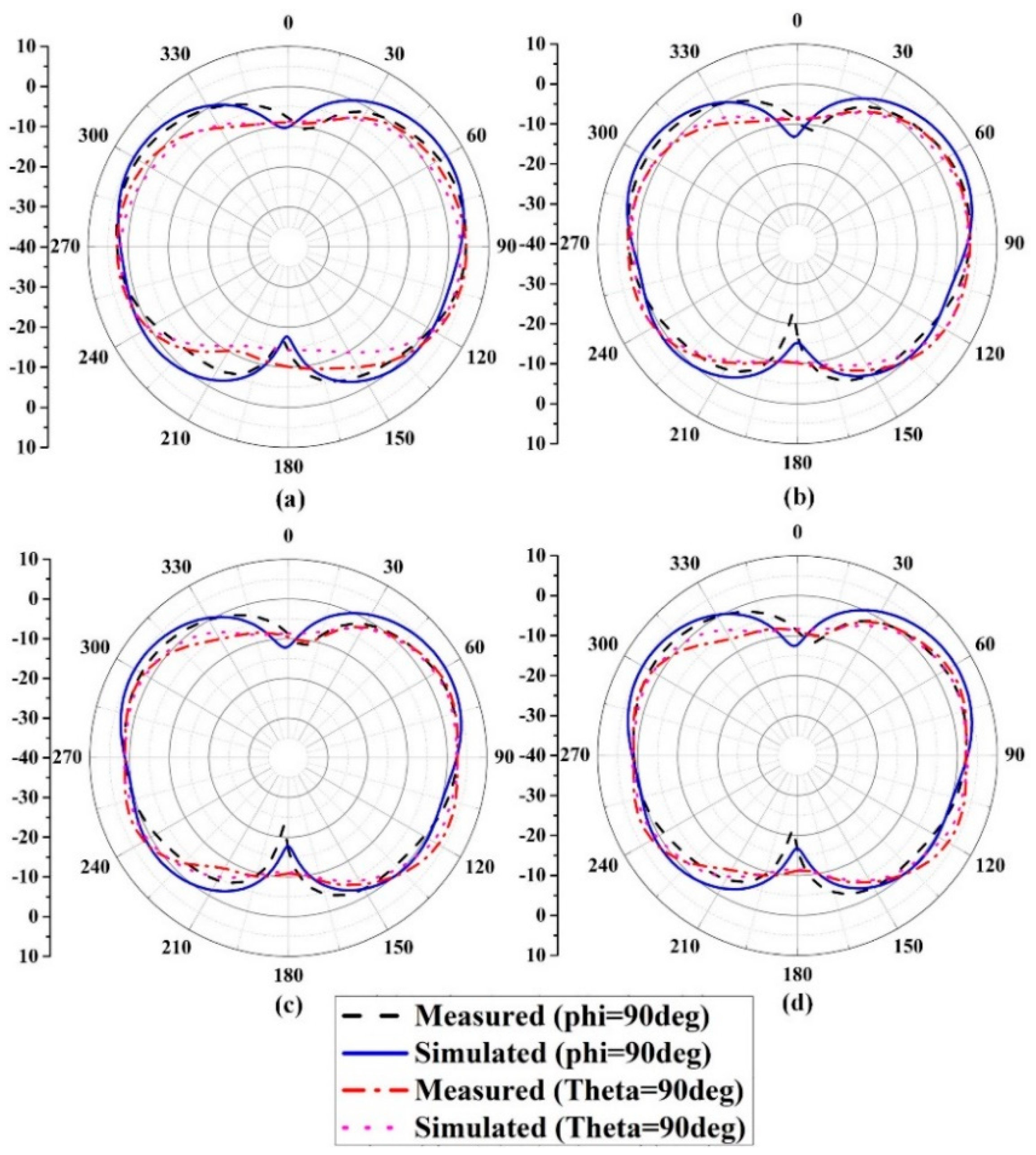
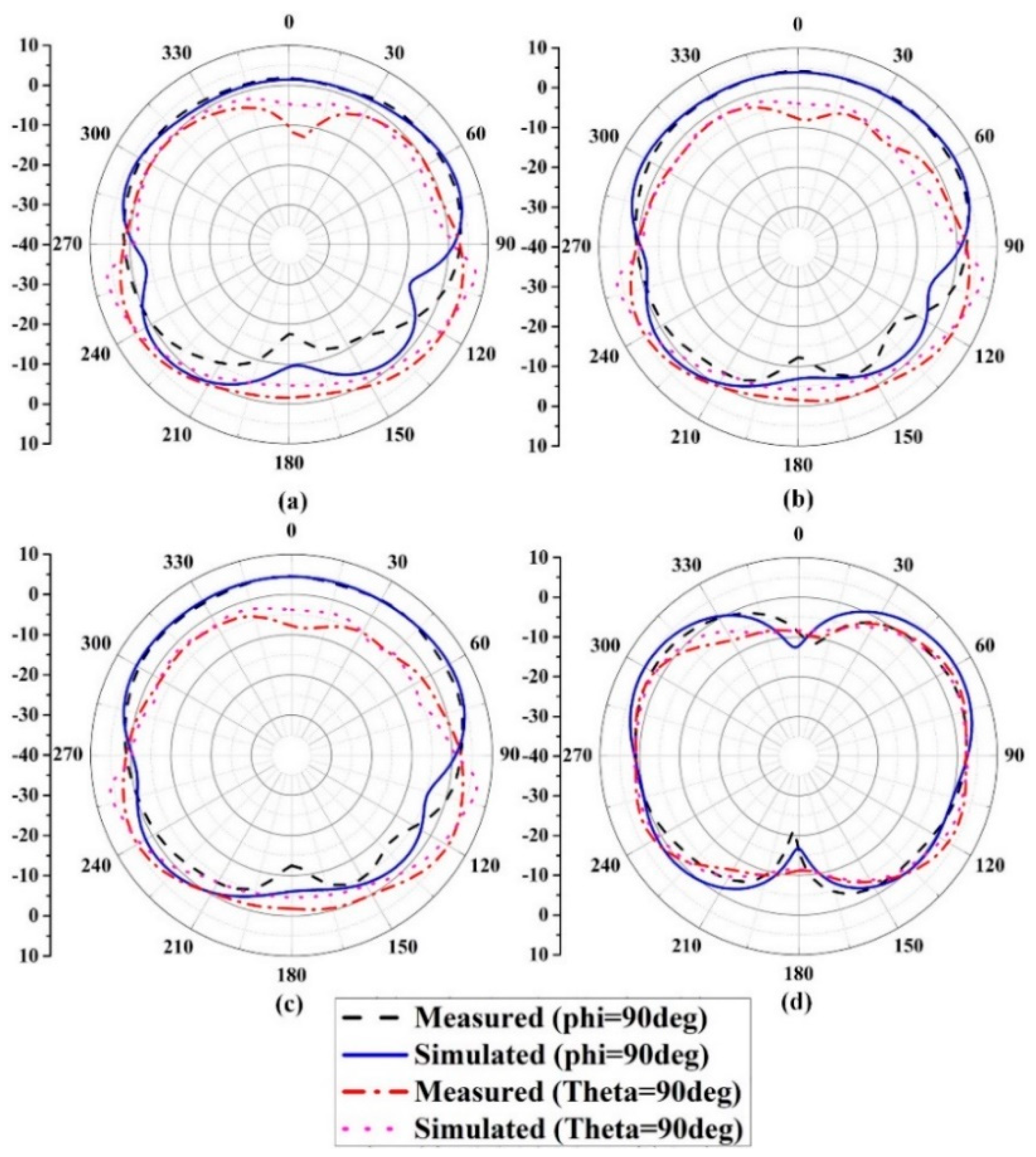
The far-field characteristics of the eight-element MIMO antenna are measured using the STAIMO Star Lab 6 GHz measurement chamber. When one antenna is excited, the remaining antenna elements are connected to a matching load.
Figure 8 and
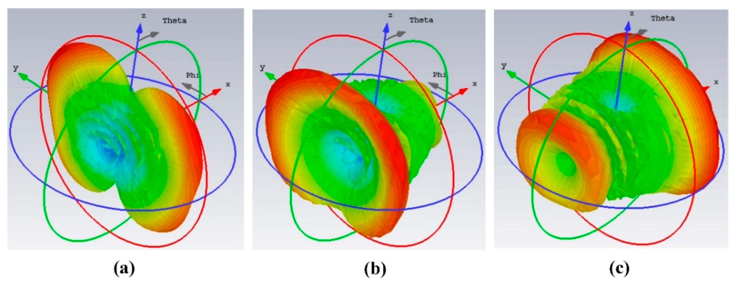
Figure 9 display the measured and simulated radiation patterns in yoz plane and xoy plane at 4.3 GHz and 5.5 GHz. It can be seen that the radiation patterns of the prototype are relatively stable and the experimental results are coincident with the results of numerical calculation. Slight distortion may be caused by the effect of testing cables and fabrication imperfections. Moreover, the simulated 3D radiation beams of the array at 0, 30, and 60 scanning angles are displayed in
Figure 10, which shows that the radiation beam of the array changes with the scanning angles.
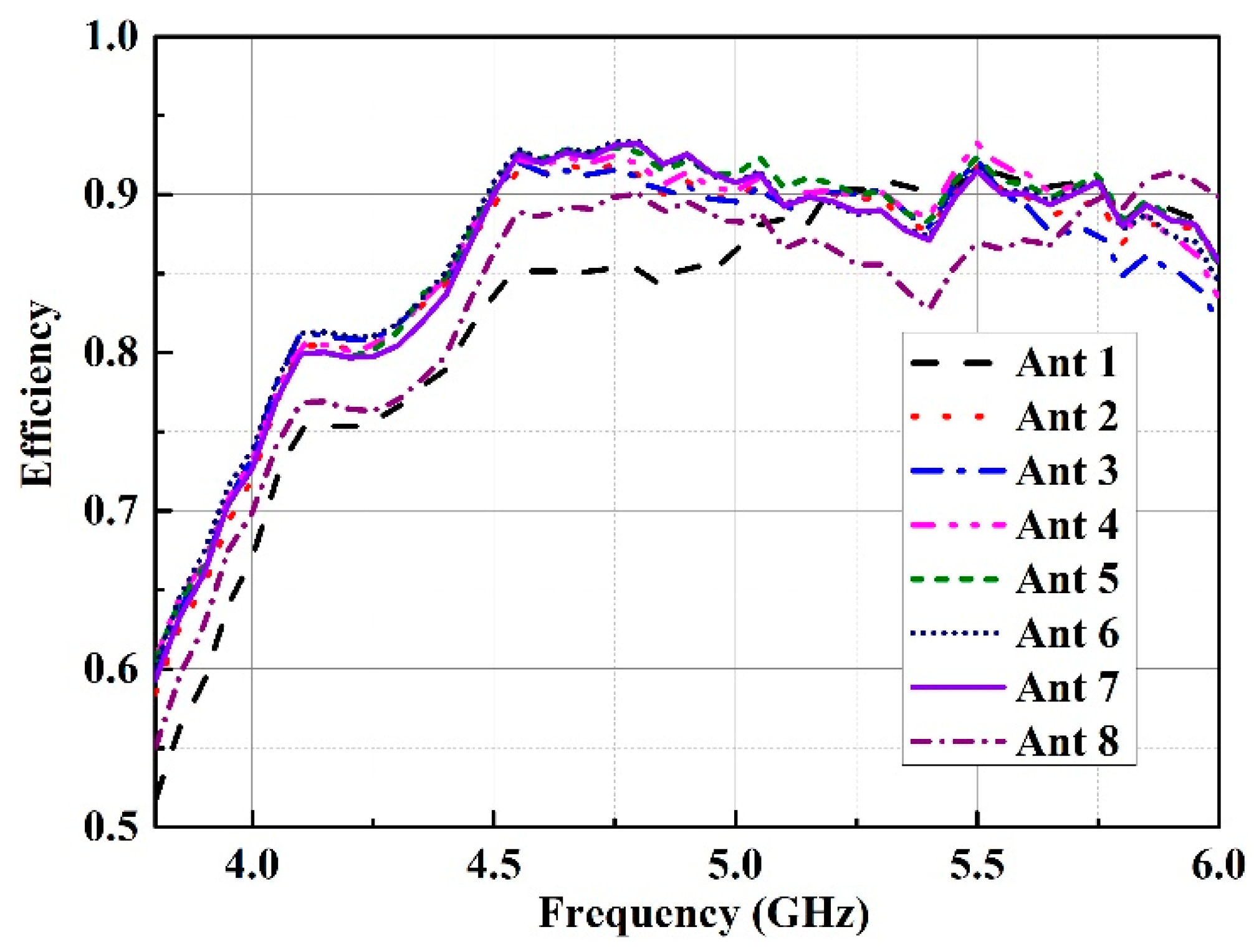
As limitations of the test conditions of anechoic chamber and wide application of the spectrum in sub-6 GHz band of 5G communications, the measured efficiency of the eight antennas below 6 GHz are presented in
Figure 11. As shown in
Figure 11, the measured efficiencies of Ant 1–Ant 8 are 52%–93% over the operating band.
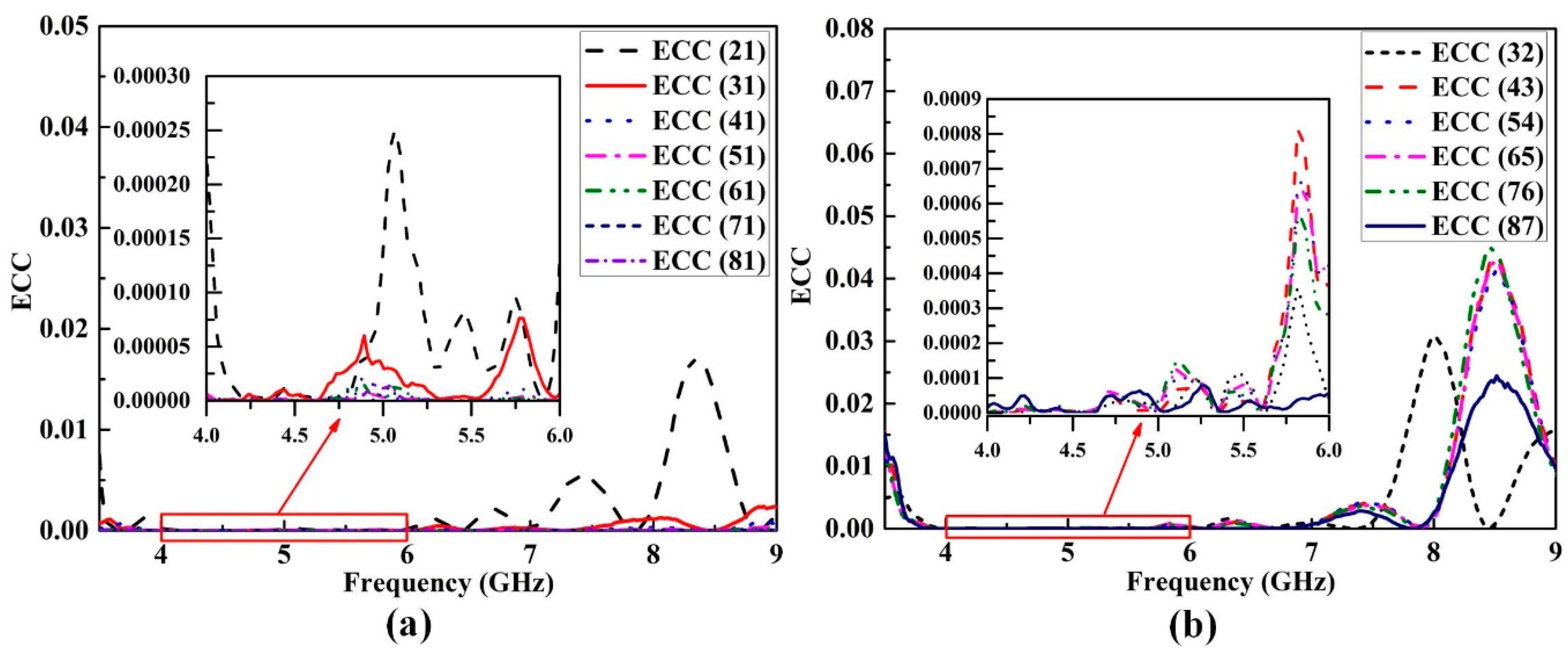
Envelope correlation coefficient (ECC), as an important index, is calculated to evaluate the diversity performance of the MIMO antenna. Here, typical ECC between element 1 and other elements and ECC between the rest of the adjacent elements are calculated using the equation in [
18]. As shown in
Figure 12, the results of ECC for any two elements are lower than 0.05 across the working band, which can meet the specific criterion of value (<0.5) for MIMO applications.
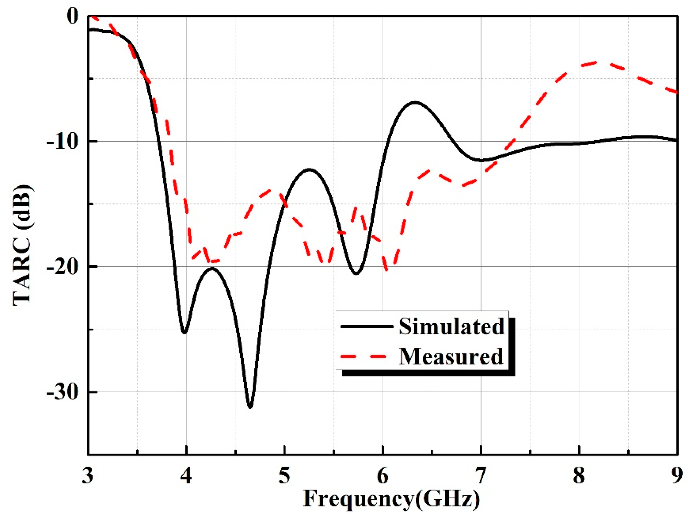
In order to better characterize the bandwidth of MIMO antenna, the total active reflection coefficient (TARC) [
19] needs to be calculated. TARC is defined as the ratio of the square root of total power divided by the square root of the total incident power [
20]. For an eight-port MIMO system, TARC can be described using the method in [
21], as shown in Equation (1):
where
Si can be expressed as follows:
The TARC value of <0 dB is desirable for a MIMO system [
21]. The simulated and measured TARC curves in decibels are displayed in
Figure 13. The measured results indicate that the value of TARC for the proposed antenna is less than −10 dB within the band of 3.83–7.25 GHz.
The performance comparisons between other multi-element MIMO antenna array in the previous paper and the eight-element MIMO antenna design are listed in
Table 2. When compared to previous designs, the elements of the proposed design are placed adjacent to each other with a spacing of 0 mm, and high isolation is achieved without introducing any extra decoupling structure. Moreover, the proposed design has a simple structure and flexibly extensible characteristic, which makes it more appropriate for modern 5G communications. Due to the inverted L-shape strips loaded on the ground, self-isolation property is achieved, which makes the proposed MIMO antenna extensible in one direction (x-direction). In the next step, we hope to further design the antenna such that extensibility and self-isolated property can be obtained in two directions (x-direction and y-direction), which can further improve the performance of the MIMO antenna and expand its application scenarios.

 ,
, 


