Improved Buffer-Aided Multi-Hop Relaying with Reduced Outage and Packet Delay in Cognitive Radio Networks


1
Department of Electrical Engineering, National University of Sciences and Technology (NUST), Islamabad 44000, Pakistan
2
Department of Electrical and Computer Engineering, COMSATS University, Islamabad 45550, Pakistan
*
Author to whom correspondence should be addressed.
Electronics 2019, 8(8), 895; https://doi.org/10.3390/electronics8080895
Submission received: 9 July 2019
/
Revised: 31 July 2019
/
Accepted: 11 August 2019
/
Published: 14 August 2019
(This article belongs to the Section Microwave and Wireless Communications)
Abstract
:Cognitive radio networks have emerged to exploit optimally the scarcely-available radio spectrum resources to enable evolving 5G wireless communication systems. These networks tend to cater to the ever-increasing demands of higher data rates, lower latencies and ubiquitous coverage. By using the buffer-aided cooperative relaying, a cognitive radio network can enhance both the spectral efficiency and the range of the network; although, this could incur additional end-to-end delays. To mitigate this possible limitation of the buffer-aided relaying in the underlay cognitive network, a virtual duplex multi-hop scheme, referred as buffer-aided multi-hop relaying, is proposed, which improves throughput and reduces end-to-end delays while keeping the outage probability to a minimum as well. This scheme simultaneously takes into account the inter-relay interference and the interference to the primary network. The proposed scheme is modeled as a Markov chain, and Monte Carlo simulations under various scenarios are conducted to evaluate several key performance metrics such as throughput, outage probability, and average packet delay. The results show that the proposed scheme outperforms many non-buffer-aided relaying schemes in terms of outage performance. When compared with other buffer-aided relaying schemes such as max-max, max-link, and buffer-aided relay selection with reduced packet delay, the proposed scheme demonstrated better interference mitigation without compromising the delay performance as well.
1. Introduction
The emerging communication systems use higher frequency spectrum and wider bands to transmit at higher data rates. Transmission at higher frequencies limits the range. Additionally, cell sizes are also kept very small to increase frequency reuse and reduce interference. Thus, there is always a need for efficient spectrum utilization, as well as range extension to meet today’s communication requirements. The concept of relays is not new in wireless networks, which were initially used to increase the range, but with the exponential growth in usage of the electromagnetic spectrum, it is also used for improving the spectral efficiency and interference mitigation. The relaying was first standardized in IEEE802.16j [1], and later, in LTE, the use of relays was thoroughly deliberated and various advance relaying strategies considered to meet throughput and coverage requirements [2,3]. Cooperative relaying is yet another unique method for wireless networks that enhances throughput and extends the coverage of the network. In this, the job of relay selection serves as a building block to realize cooperative relaying. In earlier networks, the relays were operated in half-duplex mode to minimize problems arising due to transmission and reception in the same frequency band and same time slot. The relaying may solve some of the above-mentioned problems in wireless networks, but we still need to address the problem of efficient utilization of the frequency spectrum. According to the FCC, the existing frequency bands are not efficiently utilized in time and space. This encourages the unlicensed users to use the spectrum opportunistically.
The idea of cognitive radio (CR), first proposed by Mitola [4], allows unlicensed users, also called secondary users (SUs), to share the licensed spectrum in time and space without interfering with primary users’ (PUs) communication, thus increasing the spectral efficiency. The opportunistic use of the spectrum by the secondary users can be categorized on the basis of its existence along with the primary users [5], which could be in three possible ways, i.e., (i) underlay, (ii) overlay, and (iii) interweave. In underlay mode, which is of prime interest in our work, the SUs are allowed to transmit their data in the licensed spectrum band when PUs are also transmitting. The interference temperature model is imposed on SUs’ transmission power so that the interference at a PU receiver is within the interference temperature limit and PUs communication unaffected or minimally affected. The first cognitive radio wireless regional area network standard, IEEE 802.22 [6], was developed by the IEEE 802 LAN/MAN Standard Committee (LMSC) and published in 2011. This standard uses geo-location and spectrum sensing for spectral awareness. It was visualized that if we incorporate relaying in the cognitive radio network and somehow reduce the delays because of successive relaying, then we can get closer to the objective of the most effective utilization of the frequency spectrum.
Contributions
In this work, we consider a buffer-aided multi-hop relay integrated cognitive radio network (CRN) model characterized by the interference constraints imposed by the primary network, as well as the interference caused by users of the secondary network, i.e., the CRN. This model also takes into account the channel fading that results in fluctuating signal-to-noise ratios (SNRs) in each hop, making the average data rate, outage, and delay performance of the multi-hop cognitive network very different from that of non-cognitive networks. Under these constraints, the performance of this underlay cognitive buffer-aided relay network, operating in virtual duplex mode, is analyzed using a Markov chain-based approach. Therefore, the main contributions of this work are as follows:
- A buffer-aided multi-hop relay selection (BAMR) technique is proposed that integrates a virtual duplex multi-hop mechanism with the simple buffer-aided relaying in a CRN; this enables overcoming the possible limitation of incurring additional delays associated with simple buffer-aided relaying. The incorporation of virtual duplexing, a delay-reducing technique, primarily augments the relay selection mechanism, which in turn increases the throughput and reduces end-to-end delay.
- A Markov chain-based model of the BAMR for an underlay cognitive radio network operating in virtual duplex mode is developed. This model simultaneously takes into account the inter-relay interference and the power constraints imposed by the primary network. The interference from the primary user to the secondary user (at both the receiving relay and the destination) is also considered in the model.
- Considering finite buffers at the source and the relay cluster, the outage probability, delay, and target rate/capacity are analyzed using the developed Markov modeling framework. For the delay performance, end-to-end delay rather than the delay only at the relay nodes is considered in this work. When compared with contemporary schemes, like max-max [7] and max-link [8], the proposed scheme shows significant improvement in key performance measures that include outage probability, throughput, and average packet delay.
The rest of the paper is organized as follows. In Section 2, related work on buffer-aided schemes is discussed. Section 3 discusses the general system model and benchmark schemes in the context of the underlay CRN. Outage probability, throughput, delay, and target rate are discussed in Section 4, and results are analyzed in Section 5. We discuss various challenges that must be addressed to apply buffer-aided (BA) relay selection efficiently in 5G networks in Section 6, and finally, conclusions are given in Section 7.
2. Related Work on Buffer-Aided CRN
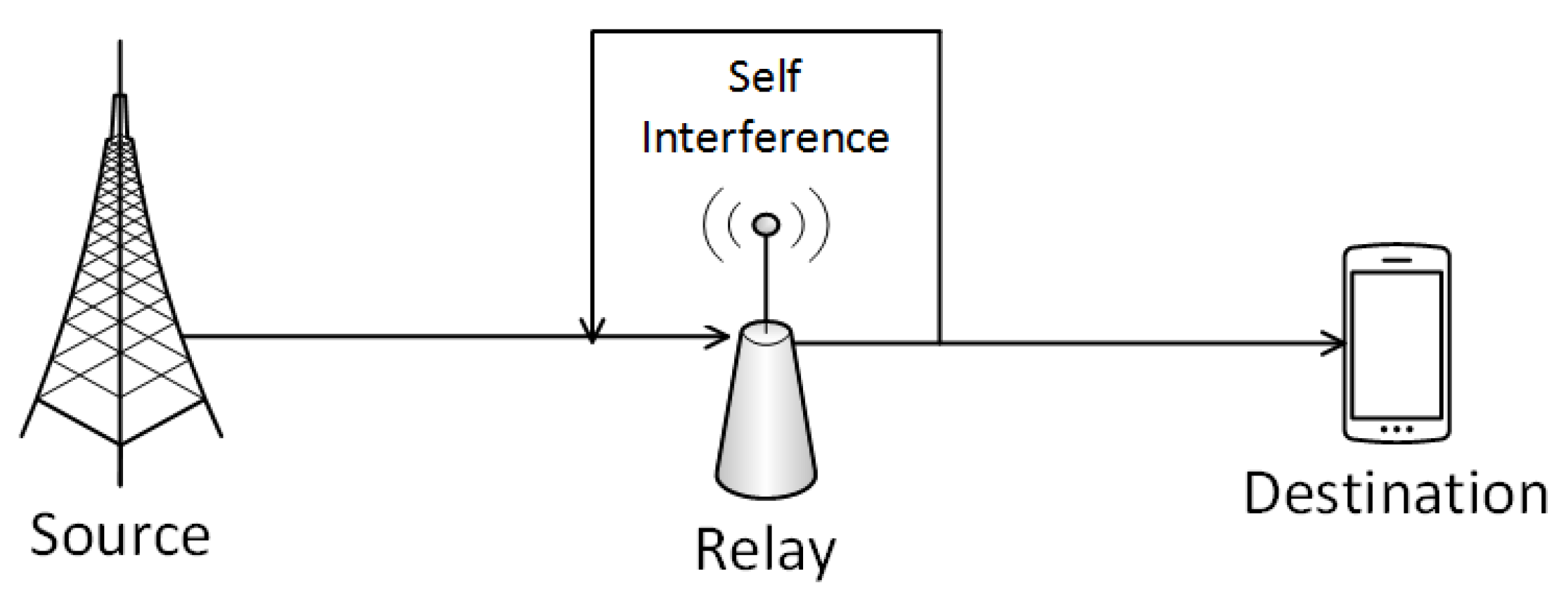
In the recent past, relays with a buffer were incorporated into cooperative relaying, which provided an additional degree of freedom in the selection of links [9] and resulted in improved throughput and a reduction in interference and outage probability, but at the expense of an increase in packet delay. Furthermore, the incorporation of buffers at the relays, i.e., buffer-aided (BA) relaying has resulted in further improvements in cognitive radio’s (CR) performance as well. The fundamental concept is to store packets when conditions are unfavorable and wait till the time when conditions become suitable for transmission. This increases the network resiliency, throughput, and diversity. In [10], the authors discussed the diversity and delay-related problems associated with a BA relay selection scheme. They proposed a unique relay selection policy based on limiting the buffer size at the relay nodes. This scheme results in reducing delay, however at the cost of increased dropping probability. The work in [11] discussed an improved version of max-link that takes into account a predetermined level of interference () that can be accepted by the primary network. The authors in [12] arbitrarily selected a relay for the primary network, and for the secondary network, selection was done from the remaining available relays. A cognitive max-ratio policy was proposed in [13], in which link selection was based on the maximum channel gain between the secondary transmitter-receiver pair over the product of the interference powers received by the secondary and primary networks In our work, we aim to provide a better insight into the whole process. Cognitive BA schemes can perform well in delay-tolerant networks (DTN); however, for time sensitive communication, there is a need to improve the delay performance in these relaying schemes. To accomplish this, it would be necessary to somehow increase the data transmission rate while keeping outage to a minimum. The scheme in [14] proposed to give higher priority to the relay-to-destination links. Source-to-relay links are considered when no relay-to-destination link can be selected. The authors assumed that this will resulted in reducing the packet queue lengths at the relay buffers, which in turn will reduce the average packet delay. However, the authors considered these relays in isolation and did not take into account accumulation of packets at the source. The practical source will have finite storage (buffer) and a finite packet arrivals/generation rate, and ignoring packet drops and delays at the source is not realistic. Moreover, it is assumed that all the relays have a fixed buffer size and do not have their own packets to transmit. Thus, this scheme does not represent a realistic scenario and may result in inefficient use of radio resources. Alternatively, if relays can operate in full-duplex mode, simultaneously transmitting and receiving data in each time slot, then throughput can be increased while keeping delay to a minimum. A general representation of full-duplex relaying is shown in Figure 1, but practically, such an implementation is very challenging because there will be strong self-interference between the transmitting and receiving RF chains
Recent works [15,16] discusses how the effect of self-interference can be minimized in full-duplex relays by employing a mixed analog-digital method. First, some analog partial self-interference cancellation technique is employed, thus preventing the receiver’s analog-to-digital conversion (ADC) from being saturated by the transmitter power. This is then followed by digital self-interference cancellation in the baseband domain. In some schemes, self-interference is effectively canceled out by utilizing multiple antennas for transmitting signals. Now, the transmitted signal will superimpose out of phase and therefore cancels at the receiver antennas. In another recent work [17], isolation between the transmitter and receiver was achieved by using a signal splitter and a single antenna
The concept of using multiple antennas can be utilized to mitigate the effect of self-interference and to isolate the receiver from the transmitter. This can be realized by integrating antennas of physically-separated/distributed nodes, into one system. While each node will be operating in half-duplex mode, but their receivers will not get saturated due to physical distance from the transmitter. We would apply such a virtual full-duplex (VFD) relay scheme formed by two-half duplex relays in our proposed buffer-aided cognitive relaying scheme.
As previously mentioned, this can be seen as the distributed version of full-duplex relaying based on multiple antennas. At each time slot, one of the relays will be in receiving mode, accepting data from the source, while another relay will be in transmitting mode, sending decoded data to the destination, in the same time slot. The role of the relays is swapped in each time interval. This relaying operation is known as successive relaying [18,19]. This way, the source can send a new message to the destination in every time slot as if a full-duplex relay was employed. It is thought-provoking to notice that the network topology so formed seems closer to the well-known diamond relay network, with the addition of one interfering link between the two relays, as shown in Figure 2. Here, one relay will be in transmit mode, while the other will be in receiving. As in full-duplex relaying, one of the main bottleneck is self-interference, thus successive relaying is handicapped by inter-relay interference. For the given successive relaying operation, an upper bound on the achievable rate is easily obtained as follows:
where C is the channel capacity and B is the bandwidth; this will be referred to as the successive upper bound. Figure 3 gives an overview of full-duplex and virtual full-duplex, i.e., the successive relaying also discussed in [9].
Various coding schemes can also be used to improve performance under interference. For non-interfering relaying models, it was deliberated in [20] that the full-duplex (FD) scheme performs better than others. This can be realized by locating each relay far from others or in a fixed relay network using highly-directional antennas [21,22]. Again, it was argued in [23] that since the source has accurate information of the relays, transmit signal, and inter-relay interference channel , by using the dirty paper coding (DPC) method, it can completely remove the known interference at the desired receiver. Therefore, successive relaying in combination with DPC can mimic the performance of an ideal full-duplex relay in a two-hop network with each relay still operating in half-duplex mode. However in this work, a multi-hop network has not been well studied. In [24], the authors presented a multi-hop decode and forward (DF) scheme and derived a closed-form expression. A multiple-hop DF scheme cannot outperform an ideal full-duplex scheme because of the delays involved in decoding the message first. Thus, the resulting scheme achieves a gap that scales logarithmically with the number of nodes. Furthermore, the proposed quantize-map-and-forward (QMF) scheme is a special case of short-message NNC(SNNC) [25] and has lower decoding delay and complexity through successive decoding instead of joint simultaneous decoding as in [26,27]. In addition, it was shown that compute and forward (CoF) could achieve the upper bound within a 0.5-bit duration if the inter-relay interference level tends to be an integer. An upper bound was also derived that was independent of the number of relays (K) and coincided with the successive upper bound .
3. Preliminaries and System Model
We modeled a buffer-aided relay network with virtual duplexing capabilities. In our model, sources communicate with their corresponding destinations through relays. The channel sate information (CSI) is initially exchanged between the relays and the source-destination pair. When this phase is completed, a centralized/distributed algorithm selects the best relay to achieve a successful communication between the source and destination.
3.1. Preliminaries
The relaying strategy can be either amplify and forward (AF) or decode and forward (DF). While a DF relay decodes, re-modulates, and retransmits the received signal, an AF simply amplifies and retransmits the signal without decoding. Compared to an AF relay, the complexity of a DF is significantly higher due to its full processing capability. In our model, we used the DF relaying strategy because it will result in better SNR at the destination with less power requirements at the relays, thus, the interference temperature control level at the primary can be achieved efficiently.
Figure 4 shows various techniques of identifying interference to the primary network, which are grouped under two main types: the geo-location technique and spectrum sensing [28]. As mentioned earlier, IEEE 802.22 uses both geo-location and spectrum sensing for spectral awareness. Figure 5 shows how geo-location-based interference management can be used to minimize the interference to the primary network.
3.2. CSI and Buffer State-Based Scheme
Channel state information (CSI) represents the characteristics of a communication link between the transmitter and receiver. It describes how a propagating signal from the transmitter to the receiver will be affected by effects such as fading, scattering, and power decaying with increasing distance. The knowledge of CSI makes the transmitter adapt to current channel conditions, which results in a reliable communication at a higher data rate. There can be more than one category of CSI that is instantaneous and statistical. The instantaneous case is acquired if the channel is varying slowly. In the case where the channel is varying very fast, we go for statistical CSI, since the mean and variance remain constant for a relatively longer time. In most cases, the receiver can accurately track the instantaneous state of the channel from pilot signals that are typically embedded within the transmissions. However, for the transmitter, there are two methods to obtain CSI from the receiver. The first one is based on the channel reciprocity principle, and the second one uses feedback from the receiver. In frequency-duplexed systems, where the up-link and down-link are apart in frequency, the link fading is not reciprocal, and thus, the CSI must be conveyed through feedback, which may incur round-trip delays that are not negligible with respect to the coherence time of the CSI being reported. Therefore, the transmitter is usually deprived of instantaneous CSI. In time-duplexed systems, in contrast, the links are reciprocal as long as the coherence time of the fading process exceeds the duplex time. Thus, the transmitter may have access to reliable CSI at low and moderate levels of mobility. In our work, the channel is sensed, and CSI at the receivers of relays are exchanged among the relays. With regards to instantaneous CSI or statistical CSI, in each case, the approach is different. For simplicity, the model in this work assumes that the location of the primary receiver and instantaneous CSI are available. In this work, a secondary power threshold is adapted for simulations. Figure 6 and Figure 7 show the sequence of CSI exchange among the relays and primary network, in a centralized and distributed manner, respectively [9].
3.3. System Model
In this work, we consider a secondary system consisting of a source (S), with a large but finite buffer of size (M), and a Poisson packet arrival rate. A destination (D) and “K” buffer-aided relays with buffer size L in between have a single antenna. The primary system in the vicinity has a transmitter (T) and receiver (R) with an interference power constraint (interference temperature) (Q) at the primary receiver. The inter-relay interference is represented by , and the channel gain from source-to-relay is , while from the relay-to-destination is (relay-to-destination) links, where i and j represent the (source-to-relay) and (relay-to-destination) links. No direct communication link between the secondary source and the secondary destination is considered. A block diagram of the system model is depicted in Figure 8.
3.4. Analytical Modeling
In order to meet the power constraint requirements, the transmissions from the secondary source and the relay network must satisfy the following condition:
where is the maximum allowable interference power at the primary receiver. Similarly, the acceptable interference at the receiving relay of interest is:
where is the channel gain for the source-to-relay link and is the channel gain for the relay-to-destination link. is the secondary source transmit power, and is the transmitting relay transmit power, with the constraint imposed on these power levels. Furthermore, we assume that the source and the relay have rate-adaptation capabilities and can exploit the CSI to their advantage. Similarly, the interference channel gains from the secondary source and the transmitting relay to the primary receiver are and , respectively; while is the interference caused by the transmitting relay to the receiving relay. The primary transmitter will also cause interference to the secondary network; this interference is represented by channel gains and (secondary network receiving relay and secondary network destination, respectively). As we are considering virtual duplex relaying, therefore, in the secondary system, and transmissions are performed simultaneously by using the best pair of receiving and transmitting relays. For a given selected relay pair (i, j), the received signal at the receiving relay i and at the destination (D) is expressed in Equations (4) and (5), respectively.
where n is the additive white Gaussian Noise (AWGN) with zero mean and unit variance and , , and are the transmitter powers of the secondary source, the transmitting relay and the primary source, respectively. As we assume that direct communication between the secondary source and secondary destination is not possible, so in Equation (4), the interference by secondary transmission is not considered. For error-free decoding at the receiving relay, the will be greater than . The ratio of these two is termed as SINR and is represented by , and it should be greater than or equal to , which is the SINR required at the receiving relay for error-free decoding at the required data rate R. Similarly, at the secondary destination, should be greater than , and we again define the ratio as , which should be greater than . Thus, is the minimum SINR required at the receiving relay, as well as the secondary destination to decode the message at the required data rate. The secondary users cannot control the primary transmitter power, but must curtail its own transmit power to ensure that it remains below the threshold set by the primary network. This is ensured by applying . Here, we need to find the maximum power permitted, both at the secondary source and the relay, as well as the SINR required for the error-free decoding of information at the prescribed data rate for the secondary network. Assuming equal power split in both interfering links as in [29], we have:
Combining the two constraints, the required SINR will be as follows:
We require a certain minimum signal-to-noise ratio at the receiving relay and the destination to ensure the desired data rate R. Here, is the SNR at the receiving relay and is the received SNR at the destination. It may be noted that we may not have a and equal, but they have to be greater than to ensure the desired data rate. Thus, the relay selection protocol based on [12] yields:
Substituting the value of in the above equation, we get:
similarly, we can find:
and substituting the value of , thus we have:
3.5. Relay Selection Scheme
The objective of relay selection in CRN is to choose the best relay node such that the corresponding end-to-end throughput from the secondary source (SS) to the secondary destination (SD) is maximized, subject to the constraint that the interference at the primary destination (PD) is below a certain level. As we are using virtual duplex mode in the successive relaying scheme, which implies that the receiving relay is not the transmitting relay in the same time slot, so we use the term relay pair. We represent this pair by subscript , in our case . As shown in Figure 7, the relays and the destination exchange CSI and buffer state information. We have already derived the and , that is the SINR for both the receiving relay and the destination, while ensuring that the power constraints imposed by the primary receiver are taken into account. Using these, we initiate our relay selection process. The flow diagram of the relay selection scheme is given in Figure 9 and is summarized as follows.
- The participating relays of the cluster exchange CSI and buffer state information.
- Among all available relay-to-destination links, select the link j with the highest SINR .
- Among all available source-to-relay links, select the link i with the highest SINR .
- Check that the same relay is not selected for reception and transmission, i.e., ; if the same, then select the next best for receiving as the transmitting relay will be given priority.
- Check the transmission power constraints imposed by the primary network are met.
- If the receiving relay buffer is not full, then transmit packets to it, and if the transmitting relay is not empty, transmit packets from this relay; both may be done simultaneously, i.e., virtual duplex relaying is enabled.
- The scheme goes into outage if no link with requisite SINR is available or the receiving relay buffer is full and the transmitting relay buffer is empty, thus resulting in no change in any of the buffers, i.e., no state change occurs.
- To exploit higher data rate capability, the priority is given to the link with better SINR from , but in the case of the source buffer getting full, the priority will change, and links with higher SINR will be selected.
Therefore, in the same time slot, one relay will be transmitting, while the other will be receiving the packets, with the condition that among all available , the best is selected; while the other relay with the best link is selected for reception. It is possible that the link has a better SINR than the link. Moreover, if all links are in outage, packets can still be received and stored in the buffer at a relay. Likewise, if all links are in outage, packets can still be transmitted if the required conditions are meet. As mentioned earlier, it is also assumed that if the SINR requirements are met, then using high data rates is possible, and more than one packet can be transmitted in one time slot. To validate improvement through our scheme as compared to the scheme proposed in [14], max-max and max-link, we analyze the scheme in terms of outage, capacity, throughput, packet drop rate, and packet delay. We select the best relay pair ; starting with a link between for transmitting, followed by the best relay for receiving as shown below. Here, we are also catering for the buffer to be full or empty and the required SINR threshold level at the respective relay.
The links with the best SINR are found among all the links; both from the source-to-relay cluster and from the relay-to-destination cluster. As our scheme is based on virtual duplexing, i.e., simultaneous transmission and reception at the relay cluster, but not to and from the same relay, we incorporate a modified feature of the scheme in [14]. First, the link with the highest SINR from the relay-to-destination is selected, and then, depending on the availability of links from the source-to-relay, a link that may have higher or lower SINR may be selected. Although, transmission and reception are still simultaneous, links are given priority, which results in smaller queue lengths as higher data rates are possible in transmission from the relay-to-destination.
4. Outage Probability Analysis
The outage will occur if the instantaneous SINR for all links, that is from the source-to-relay cluster and from the relay cluster to the destination, falls below a certain target SINR corresponding to a target data rate. The probability of a successful transmission from the source-to-relay in general is given by:
and from the relay-to-destination is given by:
where is the number of available links, which are those for which the buffers of the corresponding relay nodes are not full; otherwise, no relay will be available for receiving the data. Similarly, is the number of links for those relays whose buffers are not empty.
4.1. Analysis Using Markov Chain
We analyze the outage probability using Markov chain (MC), where the nodes of MC represent all the possible states of the buffers. The change of state will only occur if there is a successful transmission or reception of packets by the relay. Since this MC is stationary, irreducible, and aperiodic, a steady state exists, i.e., . The MC is constructed in such a way that an outage occurs only when there is no change in the state of the buffers
While calculating the outage probability, we note that the scheme will be in the outage state under the following two conditions: (i) the buffers at receiving relays are full, and the buffers of the transmitting relays are empty; and (ii) the source or the transmitting relay, due to power temperature constraints at the primary receiver, cannot ensure the required SINR at their respective destinations. In the relay cluster, the number of relays are K, each with a buffer size of L. At any time, the number of data packets in each buffer determines the state. As there are K available relays and every relay is equipped with a buffer of size L, so there are states in total. The vector is defined as:
where is the number of data packets in buffer at state and . Every state corresponds to one pair of , corresponding to the number of available source-to-relay and relay-to-destination links, respectively. At state , the total number of available source-to-relay and relay-to-destination links is denoted as and , respectively,
It is clear that and . If none of the buffers is full or empty, then all links are available such that ; thus, the total number of links is 2K. However, in one time slot, by virtue of virtual duplex relaying, there could be two simultaneously active links. Assuming that at time t, the state is , then could be such that there is a relay receiving data packet, so that the number of packets in the corresponding buffer is increased, and at the same time, there is another relay transmitting data packet, while the number of packets in its buffer is decreased. It is also possible that all source-to-relay links are in outage or all relay-to-destination links are in outage. In this case, there can be only transmission or reception by a relay. Depending on which relay receives or transmits data, at time , the buffer may move from to one of the several possible states . We denote as the set containing all states that can be moved from . Now, as the channels within secondary transmission and the secondary interfering and primary interfering channels are IID (independent and identically distributed) fading channels, we can assume that the SINRs for all channels are also IID. Therefore, the probability of selecting any pair of links is or one of the links (when all links are in outage) is . Similarly, the probability of selecting any link (when all links are in outage) is again . Further, noting that the state remains unchanged if outage occurs (or decoding is not successful), the outage probabilities that moves to a state in is given by:
where, R is given by and is the rate in bps/Hz. Note that we would calculate as follows:
The outage probability depends on factors like the target data rate we want to achieve, the signal-to-interference and noise ratio, and the number of links available at any given state.
4.2. Stationary Probabilities
We denote the state transition matrix P as an matrix.
With these observations, the entry of the state transition matrix A is expressed as:
where , , , and represent the probability of outage, the probability of a packet being transmitted from the relay to the destination, from the source to the relay, and simultaneously from the source to the relay and the relay to the destination, respectively.
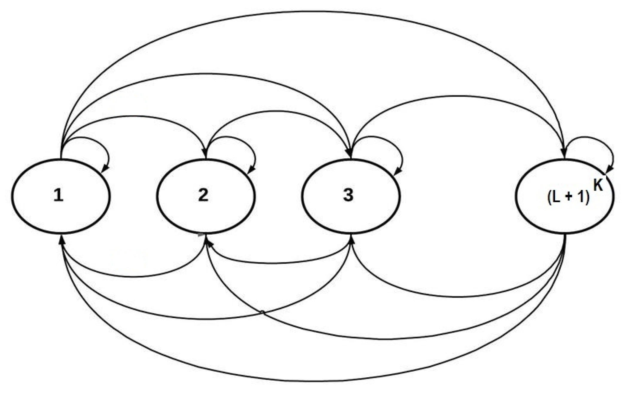
State the transition diagram in Figure 10 shows transitions from one state to another depending on the link state, these transitions are governed by Equation (33). The state transition matrix for a two-relay network , each with a buffer size of two , developed through this model, is depicted in Figure 11.
4.3. Delay Analysis
While considering buffer-aided relaying for a delay-tolerant network (DTN), like the data network, outage and packet drops are considered to be important performance metrics and not the delay; however, in time-sensitive communications, like voice communication, delay considerations are of prime importance compared to packet drops. In such networks, we are more concerned with the average delay, which is measured in time slots and is calculated by adding the number of time slots that a transmitted packet resides in the buffers (either at the source or at the relays). Unlike in [14], we considered end-to-end delay, i.e., from source-to-destination, from the time packet was generated (at the source or received at the source) to the time it reaches its final destination; we will call it the network or system delay. Based on Little’s law, the average packet delay of the system is given by Equation (34):
where and are the average queue lengths at source and the relay, respectively, and and are the average throughputs. K, L, and l are number of relays, the buffer size of each relay, and the buffer state, respectively. As we are considering virtual duplex mode, we used different relays for transmission and reception to avoid loop interference (LI). Thus, a new source packet can be served in each time slot, as in FD relay systems; so that the average delay can be approximated as the average of the two delays, that is . The average queue lengths at the buffers can be determined as:
where gives the number of packets (or the buffer length) of buffer at state and is the stationary probability of that state. On the other hand, because the probability of selecting any of the relays is the same, the average throughput at relay () is given by:
where is the average throughput of the overall relay network. For delay-sensitive transmission, the average throughput is obtained as:
where R is the average data rate of the system (without considering the outage probability). In the proposed scheme, on average, every packet requires one time slot (not necessarily consecutively) to reach the destination due to virtual duplexing, we have , and thus, ; finally, the total delay is given below.
4.4. Data Rate and Capacity Analysis
In general, the end-to-end capacity of the multi-hop system depends on the weakest link; however, in this case, the relays are operating in virtual duplex mode, so the capacity will be the average capacities of the two links. The instantaneous capacity C of a link from the source-to-relay or from the relay-to-destination is given by Shannon’s capacity relation as:
where i and j represent the source-to-relay and relay-to-destination links, respectively. In one time slot, the end-to-end capacity is , but on average, the capacity will vary and will be the average of the two links, that is:
5. Results and Discussion
A detailed analysis of the performance of the proposed buffer-aided multi-hop relay (BAMR) selection is presented in this section. This analysis is based on the results obtained using Monte Carlo simulations and includes comparison with contemporary schemes as well. At first, we have conducted simulations with a simple topology consisting of a cluster of two relays with a buffer size of two each, transmission rates of 2 bps/Hz, and the SINR varying from 0 dB to 40 dB. Later, we considered additional topologies with varying combinations of these parameters to validate the results of the first set of simulations. We adopted a distributed approach for the coordination of the relay-pair selection process, in which synchronized timers were used. The process started with the broadcast of a pilot sequence by the source, which was used to estimate the CSI by all K-relays. This was followed by the transmission of the pilot signal by the destination to the relays, which extracted the CSI. After this, each relay took turns in transmitting pilots to the other relays that calculated the CSI. Concurrently, the LI CSI was estimated. Each relay notified the rest of the relays about the status of its buffer. Now, each relay set its timer to be inversely proportional to the level of power required for successful transmission.
The outage probability decreased as the number of relays and buffer size increased, and this was evident from the fact that in general, higher diversity is obtained with more relays and a lower drop rate with larger buffer size. This coincides with our results as shown in the next two figures. Figure 12 shows the achieved average end-to-end data rate for BAMR as a function of the number of relays for various values of buffer sizes. The achievable data rate increased as the number of relays increased (higher diversity), primarily due to the availability of more link pairs. Further, for a small buffer size, the performance can degrade, but with relatively larger buffer sizes, the performance significantly improved (reduction in drop rate).
In Figure 13, the outage probability as a function of the number of relays for BAMR and three other contemporary schemes is shown. It is to be noted that with the higher number of relays to choose from, the possibility of all relays in outage was reduced. This was evident from that fact that the outage probability decreased as the number of relays increased for all four schemes; however, BAMR achieved the best performance compared to the rest of the three schemes.
Figure 14, Figure 15, Figure 16 and Figure 17 depict the impact of varying the values of SNR on various performance measures such as the data rate, outage, throughput, and delay for BAMR and other contemporary schemes.
Figure 14 shows the average end-to-end rate as a function of SNR for BAMR, as well as for the VFD, max-link, and max-max schemes. The BAMR scheme clearly outperformed the other schemes, and the performance gap became significant with the increasing values of SNR. This gain in performance was due to the fact that the proposed BAMR scheme removed the half-duplex limitation, which significantly enhanced the achievable data rate.
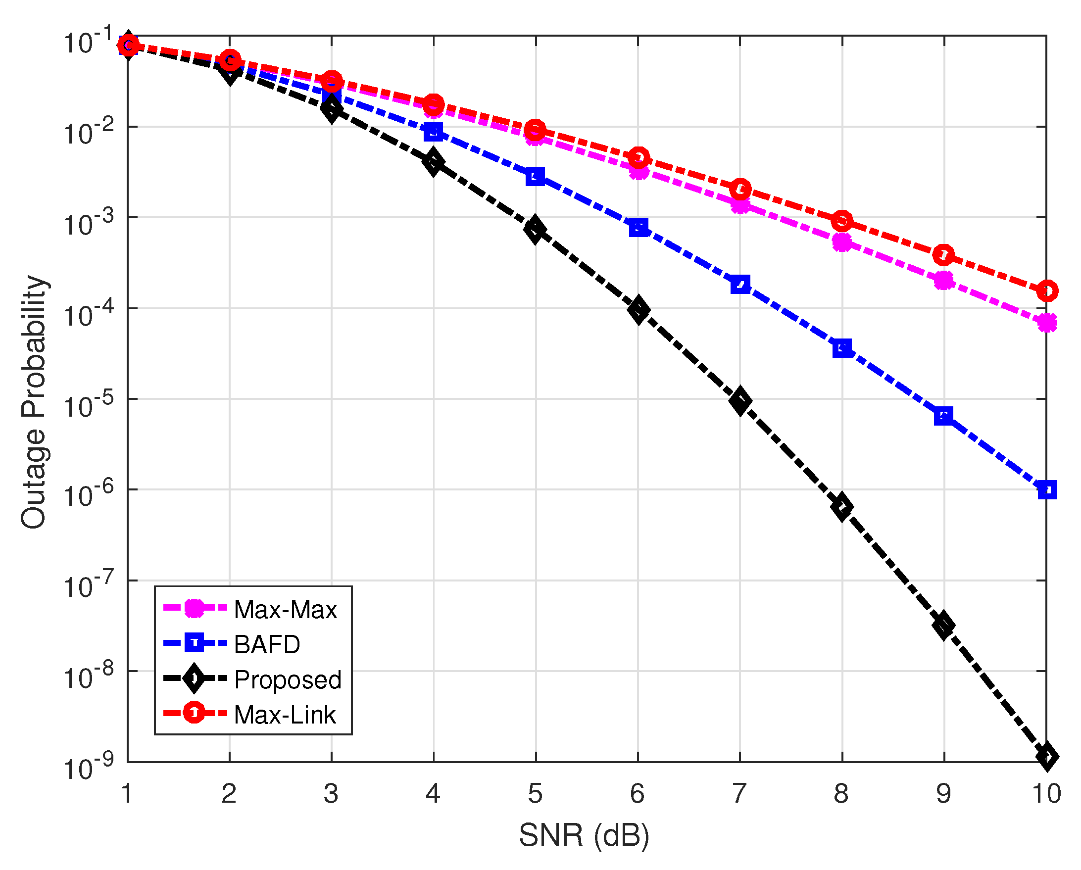
In Figure 15, the outage probability is plotted as a function of SNR for BAMR and also for the max-link, max-max, and Buffer-Aided Full-Duplex (BAFD) schemes. The results indicated the superior performance achieved with BAMR as compared to the performance achieved using the other three schemes.
The throughput performance as a function of SNR for the BAMR, as well as for BAFD, max-link and max-max schemes is depicted in Figure 16. BAMR attained the best performance of all the schemes over the range of increasing SNR values, enabling achieving higher data rates, as is shown in Figure 14 as well.
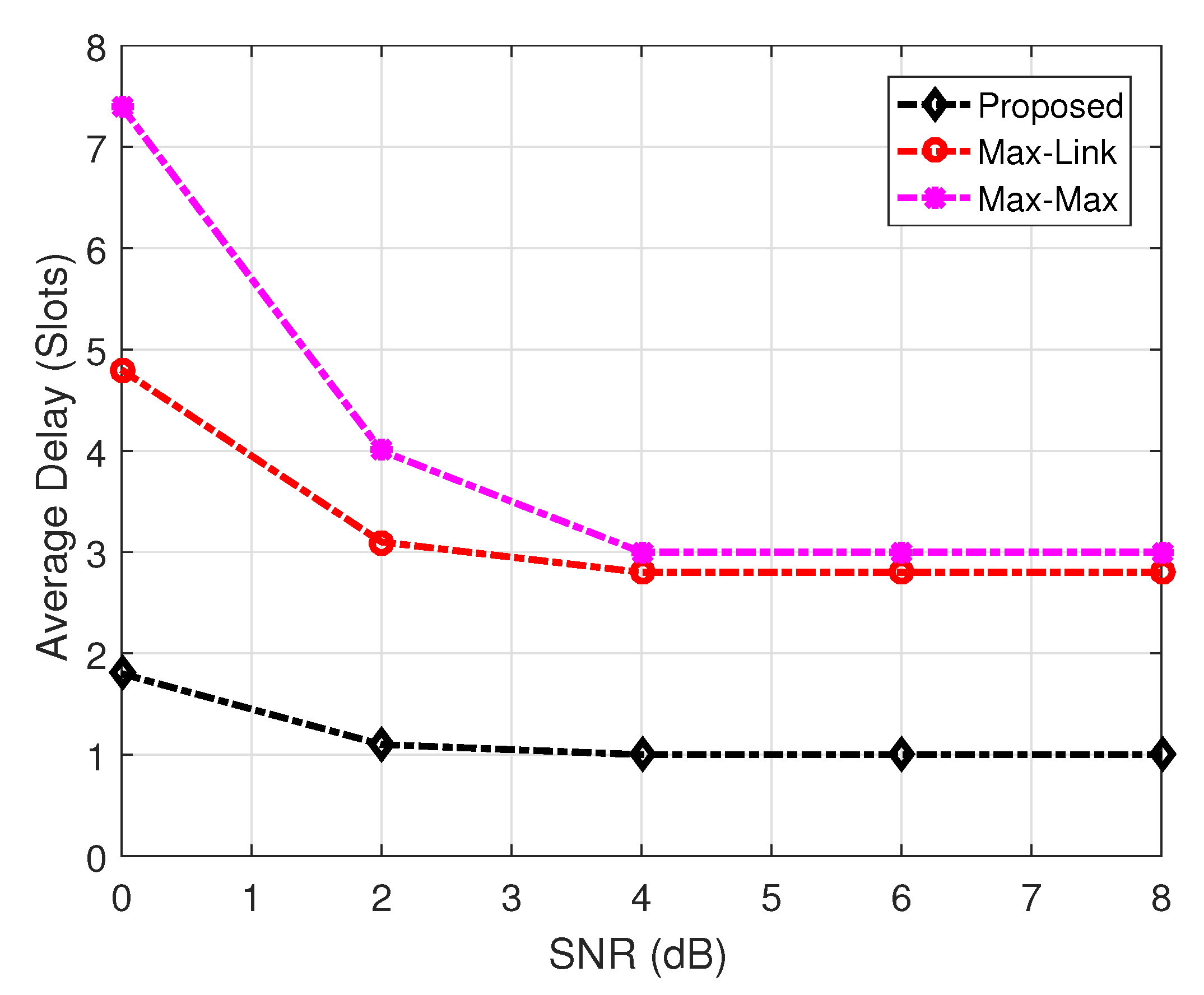
The relays with buffers enable opportunistic use of the spectrum, but its full benefits can only be accrued if we are able to transmit the packets residing in the buffers with the minimum delays. Therefore, one of the key feature of a buffer-aided scheme is the average delay, which is measured by counting the number of time slots a transmitted packet stays in a relay buffer. The average delay as a function of SNR for the BAMR, max-link, and max-max schemes is depicted in Figure 17. For this comparative analysis, the buffer size was kept intentionally low in order to keep the delay low for each buffer-aided scheme. It can be noted from the results that BAMR exhibited significantly better performance compared to that of both the max-max and the max-link schemes. The performance gain of BAMR was due to the fact that the virtual full-duplex operation was employed more frequently and packets were not trapped in the buffers for several time slots, whereas the performance degradation observed in the other two schemes resulted from the use of one single-link activation due to which packets tended to remain for several time-slots in the buffers.
6. Future Work
Though there has been significant progress in buffer-aided (BA) relay selection in the last few years, there are still challenges that need to be overcome before it can be widely adopted. Emerging Internet-of-Things (IoT) applications require ubiquitous access to the wireless medium and need flexibility in the transmission, scheduling, and distribution of data. Employing BA relays can result in significant gains in the robustness of such networks in supporting IoT applications. Device-to-device (D2D) communication can enormously benefit from BA relaying to afford improved frequency reuse and better off-loading, leading to increased revenues for the service providers. Proactive caching is another interesting domain wherein BA relay selection algorithms can be integrated to improve load balancing and reduce the bottlenecks in the core network.
6.1. Internet of Things
IoT is giving rise to new challenging and exciting applications, such as smart energy management. As the number of connected devices increases exponentially, with each exchanging data for a wide variety of applications such as smart transportation, e-health, and smart homes, the requirement for efficient use of the spectrum becomes paramount. BA relaying can enhance spectral efficiency while maintaining desirable throughput and low outage. One of the key requirements for IoT applications is flexibility in transmission, which is also the attribute of BA relaying. Thus, BA relay selection can be considered as an important enabling technique for the emerging IoT age.
6.2. D2D Communications
Device-to-device (D2D) communications will be one of the key feature in future cellular networks, with the objective of increasing the capacity of the cellular network, while keeping interference to a minimum level. Whenever the direct link fails to provide necessary performance between user equipment (UE), relay-assisted multi-hop transmission could be adopted. Besides minimizing interference, another factor to be taken into account is the optimal assignment of relays to the D2D pair without compromising the QoS of the cellular network. BA relaying provides flexibility in relay selection and thus is an important research area in D2D communications.
6.3. Proactive Caching
As discussed in [9], caching will play a significant role in future communication systems and networks. It can improve load balancing and reduce the bottlenecks in the core network. The possibility of caching data in base stations and UEs through the prediction of the demand for popular data can outline the role of cooperation and data relaying. Since context awareness and social networks are necessary characteristics for proactive caching, a wide range of BA relay selection schemes can be developed to support proactive caching.
7. Conclusions
Maximizing the utilization of the limited spectrum resource is the most critical task in a wireless communication system, as it leads to enhanced capacity, coverage, and QoS provisioning. A cognitive radio network (CRN) attempts to exploit the unused licensed spectrum of an existing network dynamically (primary network) to provision a secondary network that can optimize the spectrum utilization, as well as afford additional communication services. The integration of buffer-aided relaying in wireless networks helps to improve spectral efficiency and coverage, albeit that this could result in increased delays. In this work, the focus is on improving the performance of a CRN that includes buffer-aided (BA) relays. The proposed buffer-aided multi-hop relay selection (BAMR) scheme improves the delay performance through virtual duplexing using a cluster of relays. BAMR takes into account both the inter-relay interference and the transmission power constraint imposed by the primary network. The performance evaluation of BAMR has been carried out using Markov modeling and Monte Carlo simulations. The results, collected in terms of throughput, outage, and average end-to-end delays, have clearly demonstrated the substantial performance improvement achieved with BAMR in comparison to other contemporary schemes. BAMR takes into account the delays both at the source and the relay cluster, while ensuring better spectral efficiency and reduced outage. BAMR performs well in both DTN and non-DTN environments. It not only reduces the queue lengths at the relay buffers through prioritized link selection ability, but also keeps queues at the source to minimum lengths through virtual duplexing. The adaptive data rate feature of this scheme enables it to transmit more than one packet in a single time slot whenever a favorable condition, in terms of SINR, allows for it.
Author Contributions
Conceptualization, S.A.A.; methodology, S.A.A.; software, S.A.A.; validation, S.A.A., R.H., and S.A.M.; formal analysis, S.A.A. and R.H.; investigation, S.A.A.; resources, S.A.A., R.H., and S.A.M.; data curation, S.A.A. and R.H.; writing, original draft preparation, S.A.A.; writing, review and editing, S.A.A. and R.H.; visualization, S.A.A.; supervision, R.H., S.A.M.; project administration; Q.U.H.
Funding
This research received no external funding.
Conflicts of Interest
The authors declare no conflict of interest.
Abbreviations
The following abbreviations are used in this manuscript:
| CRN | cognitive radio network |
| BA | buffer aided |
| BAFD | buffer-aided full-duplex |
| DTN | delay-tolerant network |
| IoT | Internet of Things |
| IID | independent and identically distributed |
| LI | loop interference |
| CSI | channel state information |
| MC | Markov chain |
| DPC | dirty paper coding |
| FD | full duplex |
| LTE | Long-Term Evolution |
| PU | primary user |
| SU | secondary user |
| VFD | virtual full duplex |
| DF | decode and forward |
| AF | amplify and forward |
| CoF | compute and forward |
| AWGN | additive white Gaussian noise |
References
- Peters, S.W.; Heath, R.W., Jr. The future of WiMAX: Multihop relaying with IEEE 802.16 j. IEEE Commun. Mag. 2009, 47, 104–111. [Google Scholar] [CrossRef]
- Peters, S.W.; Panah, A.Y.; Truong, K.T.; Heath, R.W. Relay architectures for 3GPP LTE-advanced. EURASIP J. Wirel. Commun. Netw. 2009, 2009, 618787. [Google Scholar] [CrossRef]
- Parkvall, S.; Dahlman, E.; Furuskar, A.; Jading, Y.; Olsson, M.; Wanstedt, S.; Zangi, K. LTE-advanced-evolving LTE towards IMT-advanced. In Proceedings of the 2008 IEEE 68th Vehicular Technology Conference, Calgary, BC, Canada, 21–24 September 2008; pp. 1–5. [Google Scholar]
- Mitola, J.; Maguire, G.Q. Cognitive radio: Making software radios more personal. IEEE Pers. Commun. 1999, 6, 13–18. [Google Scholar] [CrossRef]
- Giupponi, L.; Ibars, C. Distributed cooperation in cognitive radio networks: Overlay versus underlay paradigm. In Proceedings of the VTC Spring 2009-IEEE 69th Vehicular Technology Conference, Barcelona, Spain, 26–29 April 2009; pp. 1–6. [Google Scholar]
- Stevenson, C.R.; Chouinard, G.; Lei, Z.; Hu, W.; Shellhammer, S.J.; Caldwell, W. IEEE 802.22: The first cognitive radio wireless regional area network standard. IEEE Commun. Mag. 2009, 47, 130–138. [Google Scholar] [CrossRef]
- Ikhlef, A.; Michalopoulos, D.S.; Schober, R. Max-max relay selection for relays with buffers. IEEE Trans. Wirel. Commun. 2012, 11, 1124–1135. [Google Scholar] [CrossRef]
- Tian, Z.; Chen, G.; Gong, Y.; Chen, Z.; Chambers, J.A. Buffer-aided max-link relay selection in amplify-and-forward cooperative networks. IEEE Trans. Veh. Technol. 2015, 64, 553–565. [Google Scholar] [CrossRef]
- Nomikos, N.; Charalambous, T.; Krikidis, I.; Skoutas, D.N.; Vouyioukas, D.; Johansson, M.; Skianis, C. A survey on buffer-aided relay selection. IEEE Commun. Surv. Tutor. 2016, 18, 1073–1097. [Google Scholar] [CrossRef]
- Poulimeneas, D.; Charalambous, T.; Nomikos, N.; Krikidis, I.; Vouyioukas, D.; Johansson, M. Delay-and diversity-aware buffer-aided relay selection policies in cooperative networks. In Proceedings of the 2016 IEEE Wireless Communications and Networking Conference, Doha, Qatar, 3–6 April 2016; pp. 1–6. [Google Scholar]
- Sultan, R.A.; Sultan, A.K.; Youssef, M. Buffered-relay selection in an underlay cognitive radio network. In Proceedings of the 2013 11th International Symposium and Workshops on Modeling and Optimization in Mobile, Ad Hoc and Wireless Networks (WiOpt), Tsukuba Science City, Japan, 13–17 May 2013; pp. 201–207. [Google Scholar]
- Darabi, M.; Maham, B.; Zhou, X.; Saad, W. Buffer-aided relay selection with interference cancellation and secondary power minimization for cognitive radio networks. In Proceedings of the 2014 IEEE International Symposium on Dynamic Spectrum Access Networks (DYSPAN), McLean, VA, USA, 1–4 April 2014; pp. 137–140. [Google Scholar]
- Chen, G.; Tian, Z.; Gong, Y.; Chambers, J. Decode-and-forward buffer-aided relay selection in cognitive relay networks. IEEE Trans. Veh. Technol. 2014, 63, 4723–4728. [Google Scholar] [CrossRef]
- Tian, Z.; Gong, Y.; Chen, G.; Chambers, J.A. Buffer-aided relay selection with reduced packet delay in cooperative networks. IEEE Trans. Veh. Technol. 2017, 66, 2567–2575. [Google Scholar] [CrossRef]
- Duarte, M.; Dick, C.; Sabharwal, A. Experiment-driven characterization of full-duplex wireless systems. IEEE Trans. Wirel. Commun. 2012, 11, 4296–4307. [Google Scholar] [CrossRef]
- Bliss, D.; Parker, P.; Margetts, A. Simultaneous transmission and reception for improved wireless network performance. In Proceedings of the 2007 IEEE/SP 14th Workshop on Statistical Signal Processing, Madison, WI, USA, 26–29 August 2007; pp. 478–482. [Google Scholar]
- Bharadia, D.; McMilin, E.; Katti, S. Full duplex radios. In ACM SIGCOMM Computer Communication Review; ACM: New York, NY, USA, 2013; Volume 43, pp. 375–386. [Google Scholar]
- Oechtering, T.; Sezgin, A. A new cooperative transmission scheme using the space-time delay code. In Proceedings of the ITG Workshop on Smart Antennas (IEEE Cat. No. 04EX802), Munich, Germany, 18–19 March 2004; pp. 41–48. [Google Scholar]
- Bagheri, H.; Motahari, A.S.; Khandani, A.K. On the capacity of the half-duplex diamond channel. In Proceedings of the 2010 IEEE International Symposium on Information Theory, Austin, TX, USA, 13–18 June 2010; pp. 649–653. [Google Scholar]
- Hong, S.; Caire, G. Virtual full-duplex relaying with half-duplex relays. IEEE Trans. Inf. Theory 2015, 61, 4700–4720. [Google Scholar] [CrossRef]
- Michalopoulos, D.S.; Karagiannidis, G.K. Bypassing orthogonal relaying transmissions via spatial signal separation. IEEE Trans. Commun. 2010, 58, 3028–3038. [Google Scholar] [CrossRef]
- Ikhlef, A.; Kim, J.; Schober, R. Mimicking full-duplex relaying using half-duplex relays with buffers. IEEE Trans. Veh. Technol. 2012, 61, 3025–3037. [Google Scholar] [CrossRef]
- Karakus, C.; Suhas, D. Opportunistic scheduling for full-duplex uplink-downlink networks. proceedings of the International Symposium on Information Theory (ISIT), Hong Kong, China, 14–19 June 2015; pp. 1019–1023. [Google Scholar]
- Muthuramalingam, B.; Bhashyam, S.; Thangaraj, A. A decode and forward protocol for two-stage Gaussian relay networks. IEEE Trans. Commun. 2012, 60, 68–73. [Google Scholar] [CrossRef]
- Avestimehr, S.; Diggavi, S.; Tse, D. Wireless network information flow: A deterministic approach. arXiv 2009, arXiv:0906.5394. [Google Scholar] [CrossRef]
- Lim, S.H.; Kim, Y.H.; El Gamal, A.; Chung, S.Y. Noisy network coding. In Proceedings of the 2010 IEEE Information Theory Workshop on Information Theory (ITW 2010, Cairo), Cairo, Egypt, 6–8 January 2010; pp. 1–5. [Google Scholar]
- Hou, J.; Kramer, G. Short message noisy network coding with a decode–forward option. IEEE Trans. Inf. Theory 2016, 62, 89–107. [Google Scholar] [CrossRef]
- Lan, P.; Sun, F.; Chen, L.; Xue, P.; Hou, J. Power allocation and relay selection for cognitive relay networks with primary QoS constraint. IEEE Wirel. Commun. Lett. 2013, 2, 583–586. [Google Scholar] [CrossRef]
- Kim, S.M.; Kim, J. Virtual full-duplex relay selection in relay-assisted cognitive radio networks. In Proceedings of the 2017 Ninth International Conference on Ubiquitous and Future Networks (ICUFN), Milan, Italy, 4–7 July 2017; pp. 12–14. [Google Scholar]
Figure 1.
Self-interference in dual-hop full-duplex relaying.

Figure 2.
Virtual full-duplex relaying concept.
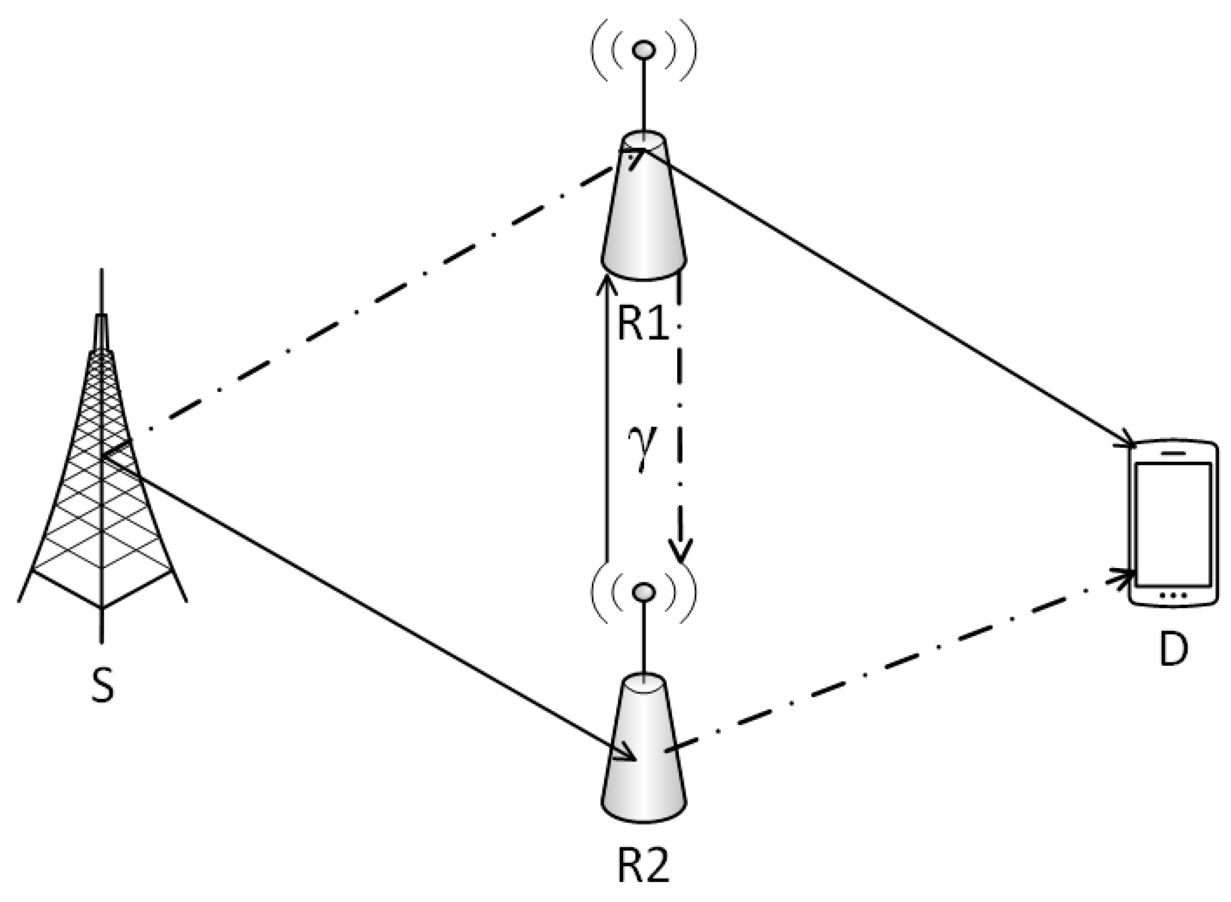
Figure 3.
Over view of full-duplex relaying.
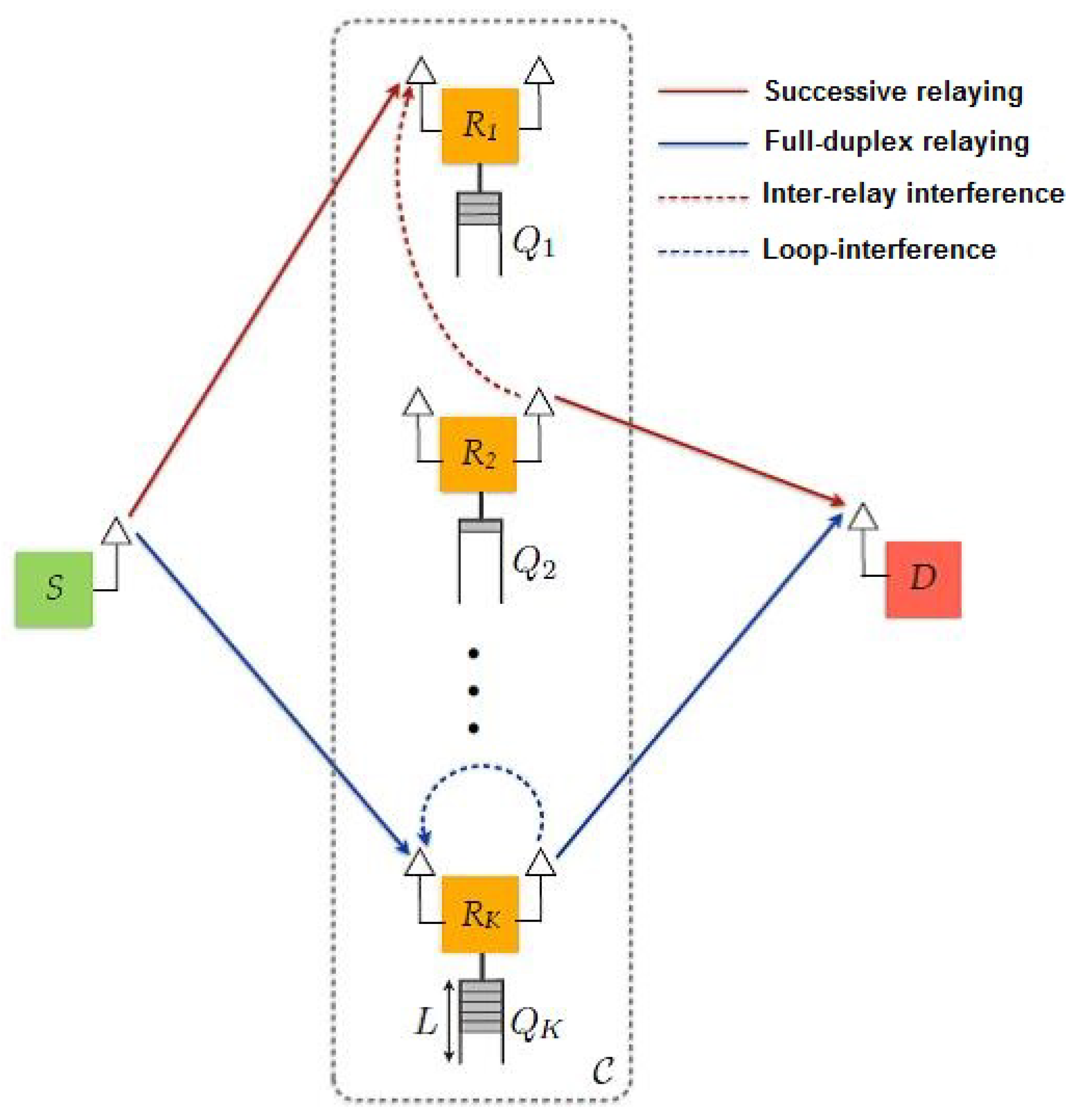
Figure 4.
Classification of interference-identifying techniques.

Figure 5.
Geo-location-based interference management.
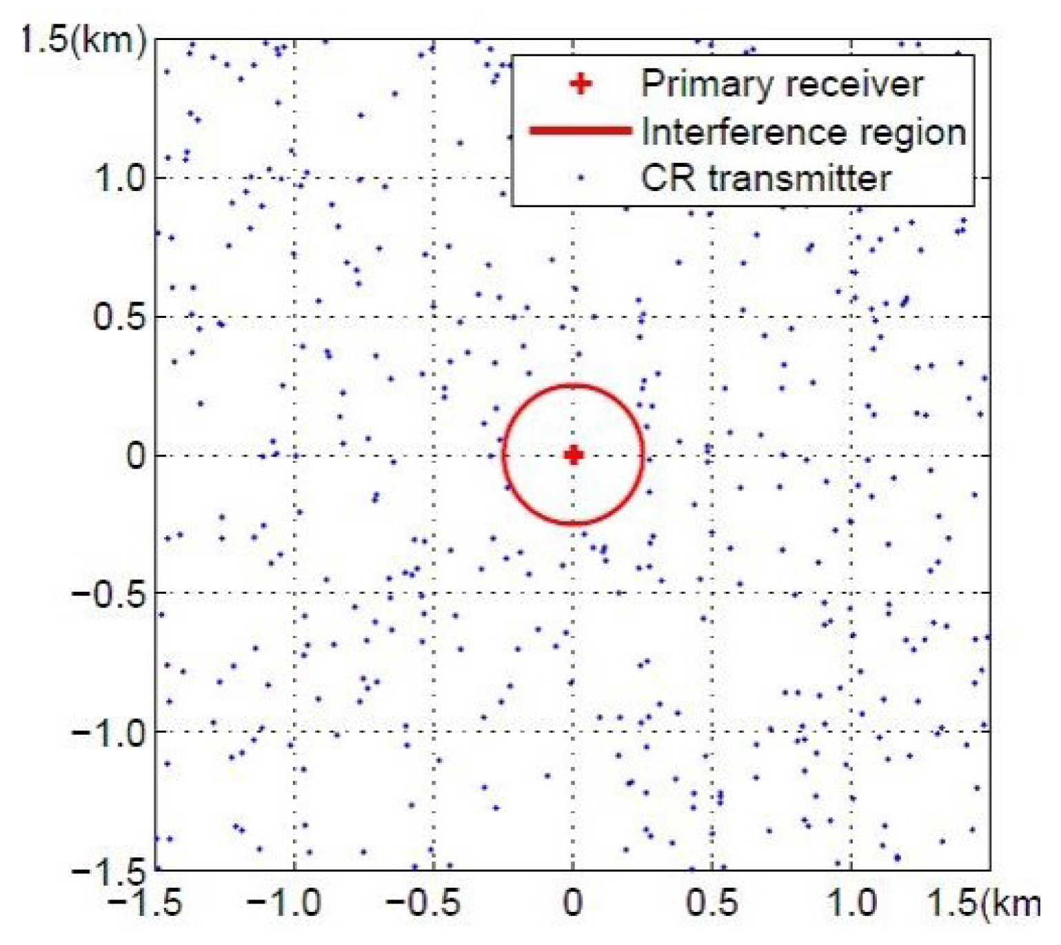
Figure 6.
Three-phase CSI and buffer state exchange.
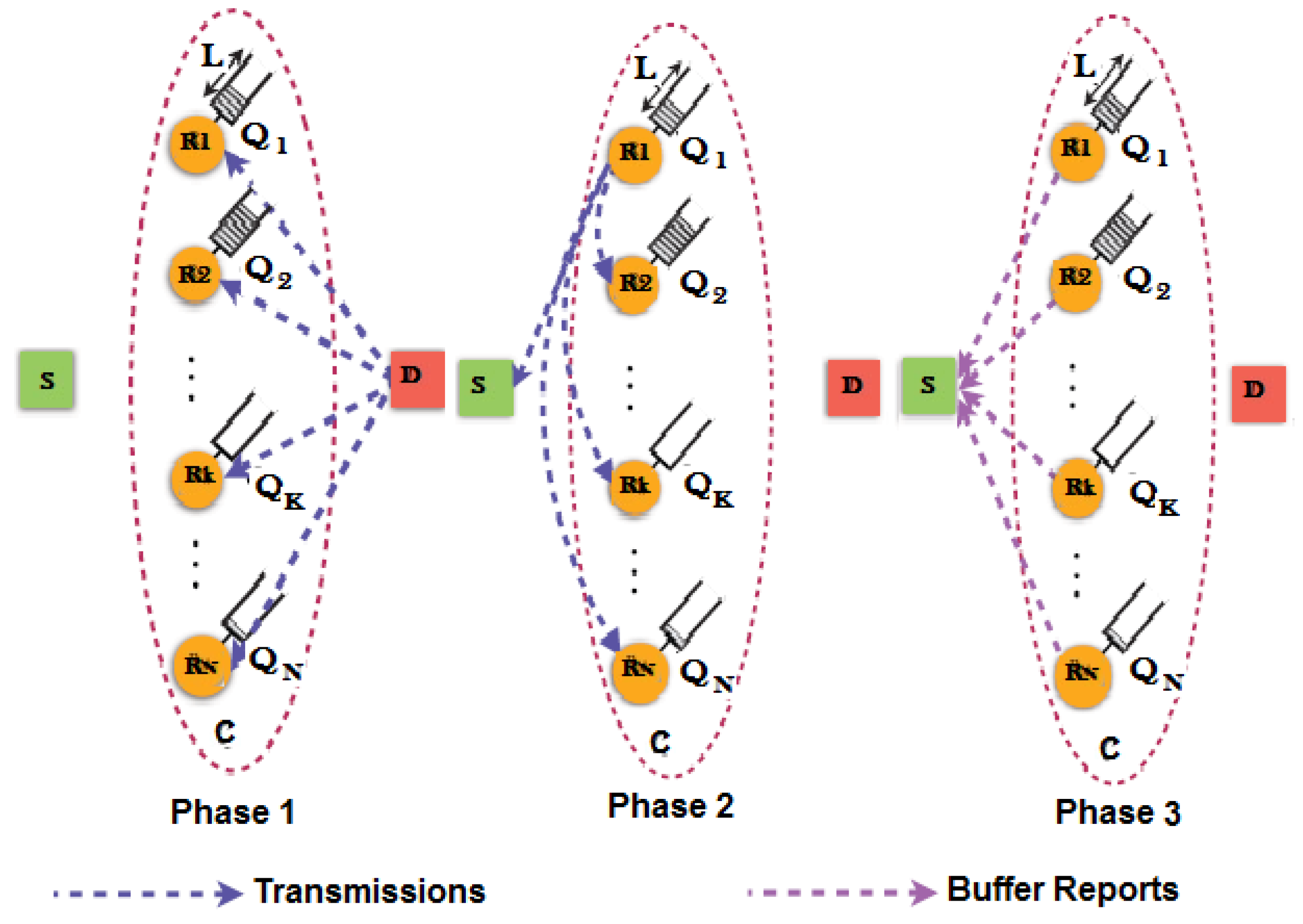
Figure 7.
Four-phase CSI and buffer state exchange.
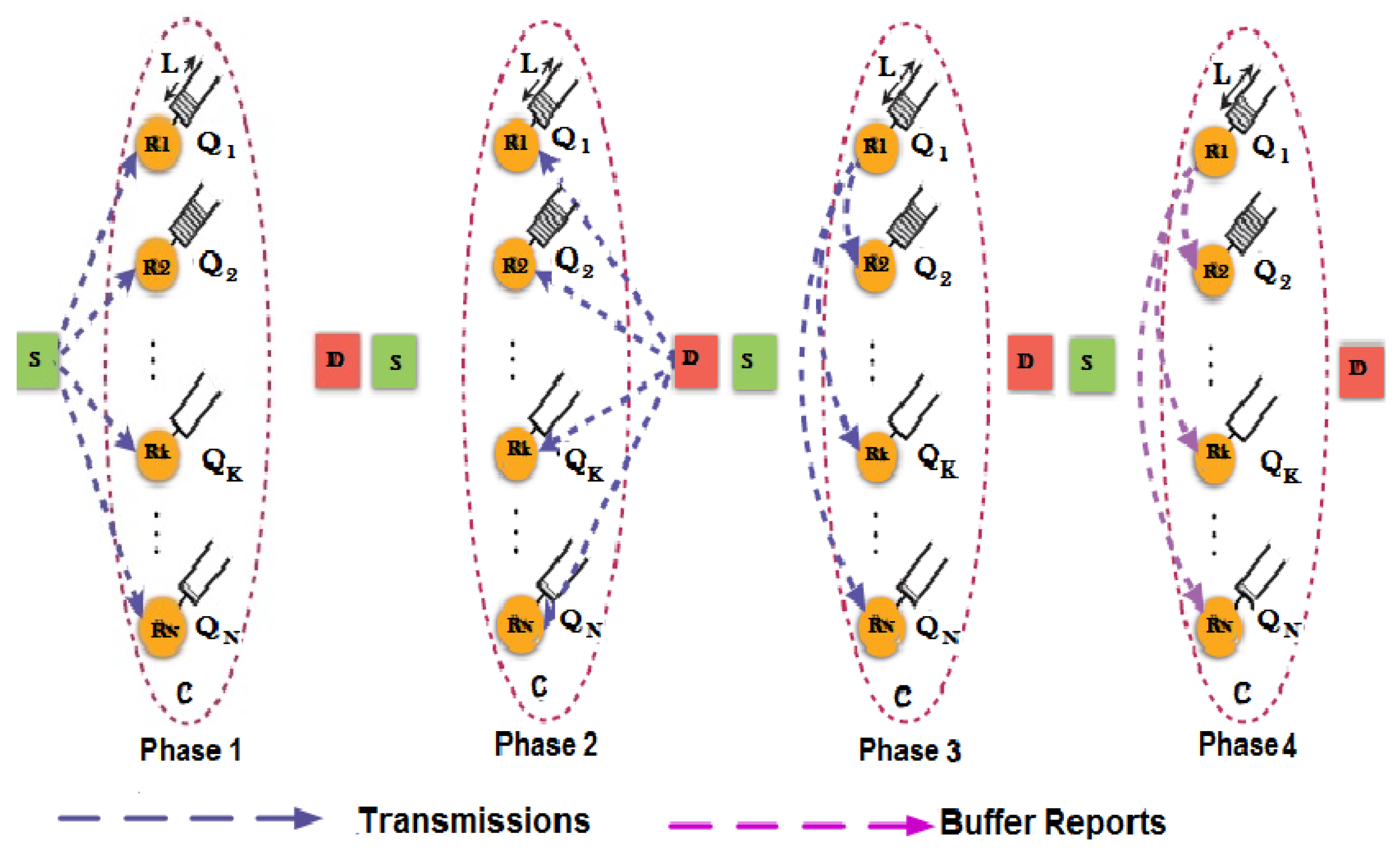
Figure 8.
System model.
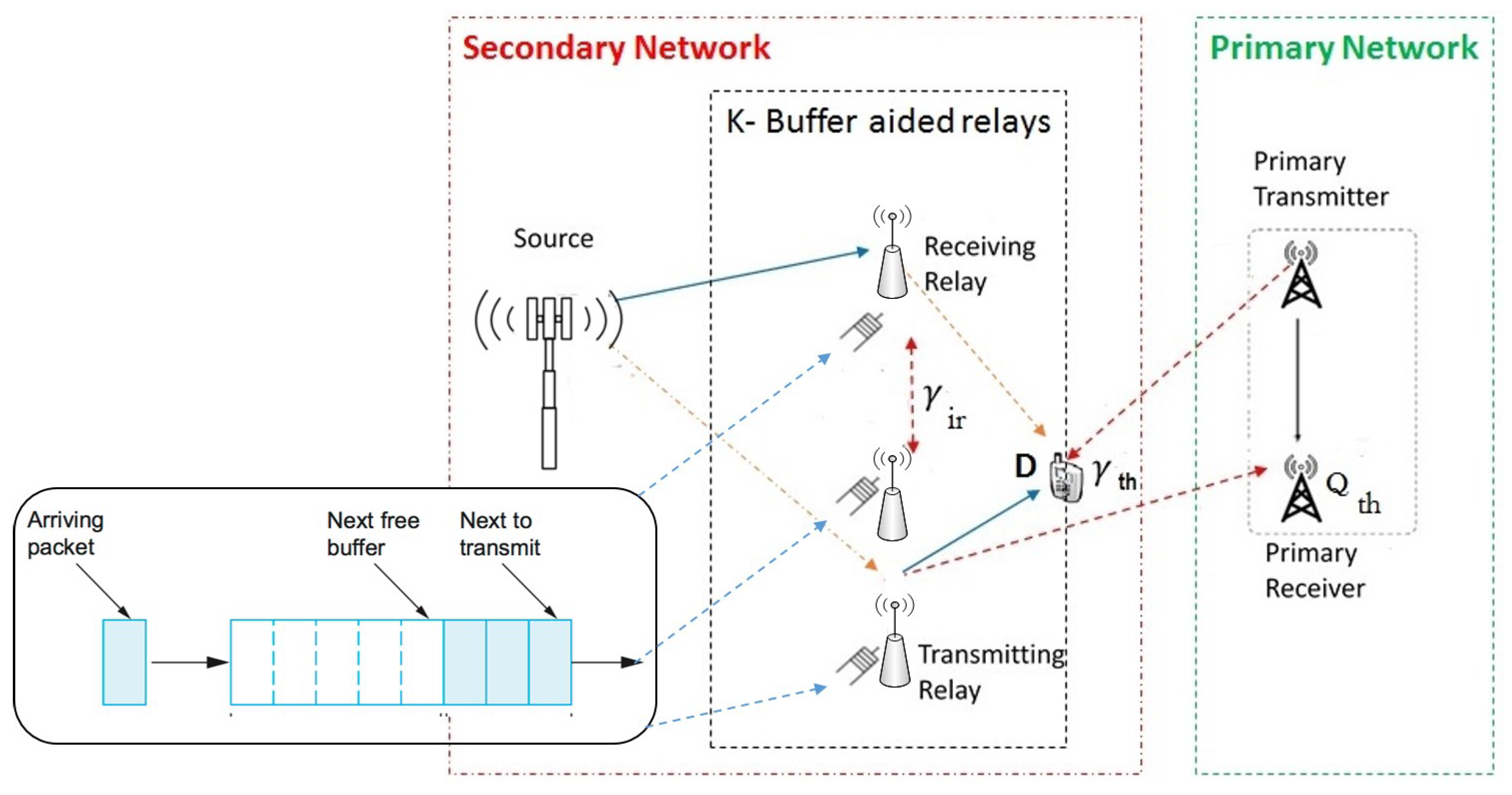
Figure 9.
Flow diagram of the relay selection scheme.
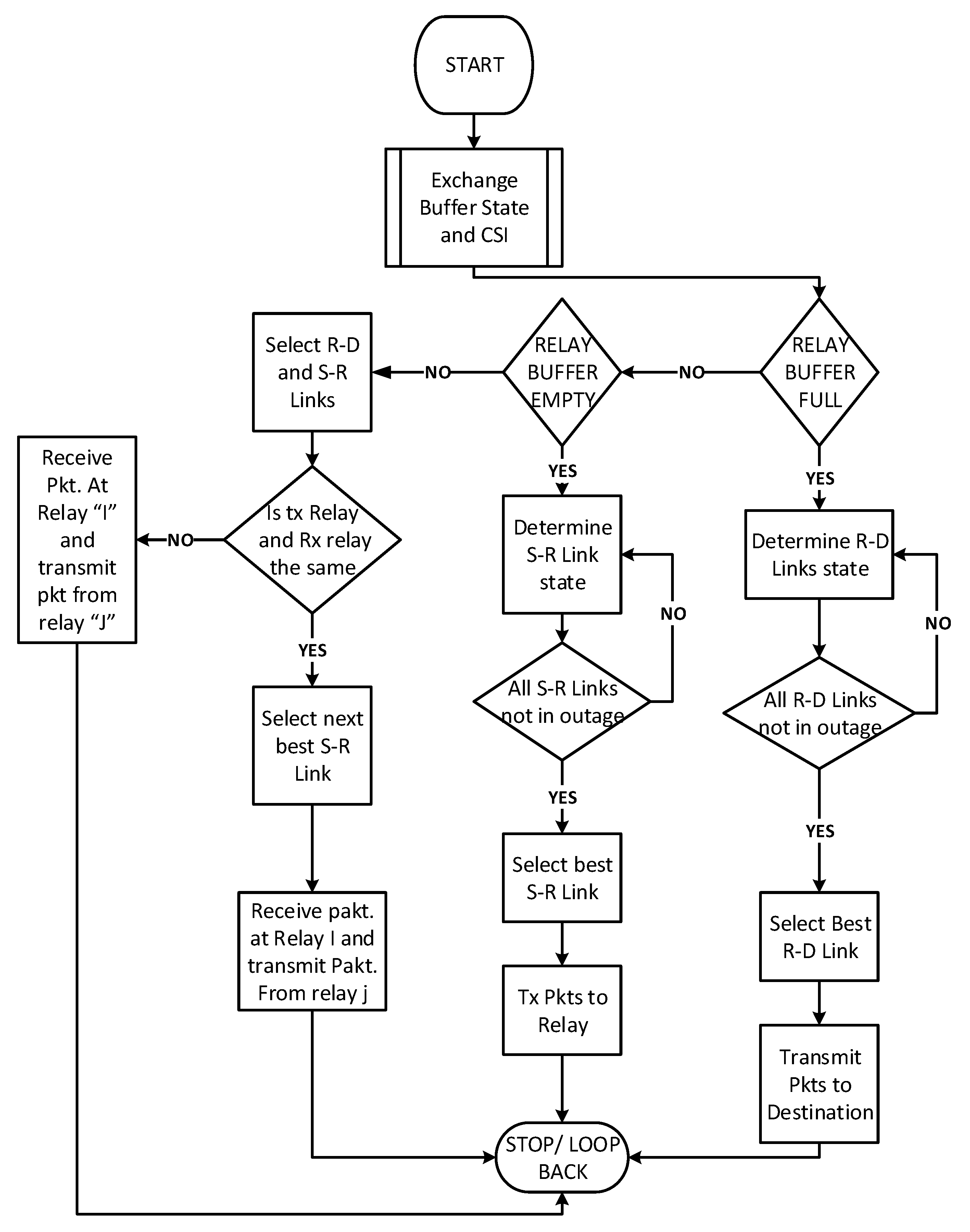
Figure 10.
State transition flow diagram, showing one or more arrival and departure.

Figure 11.
State transition matrix for K = 2 and L = 2.
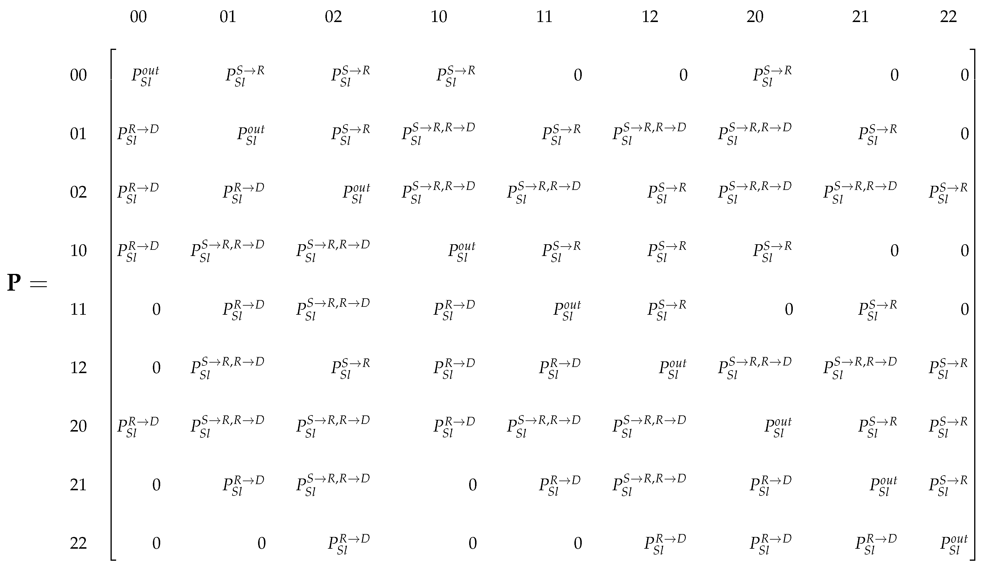
Figure 12.
End-to-end rate vs. the number of relays.
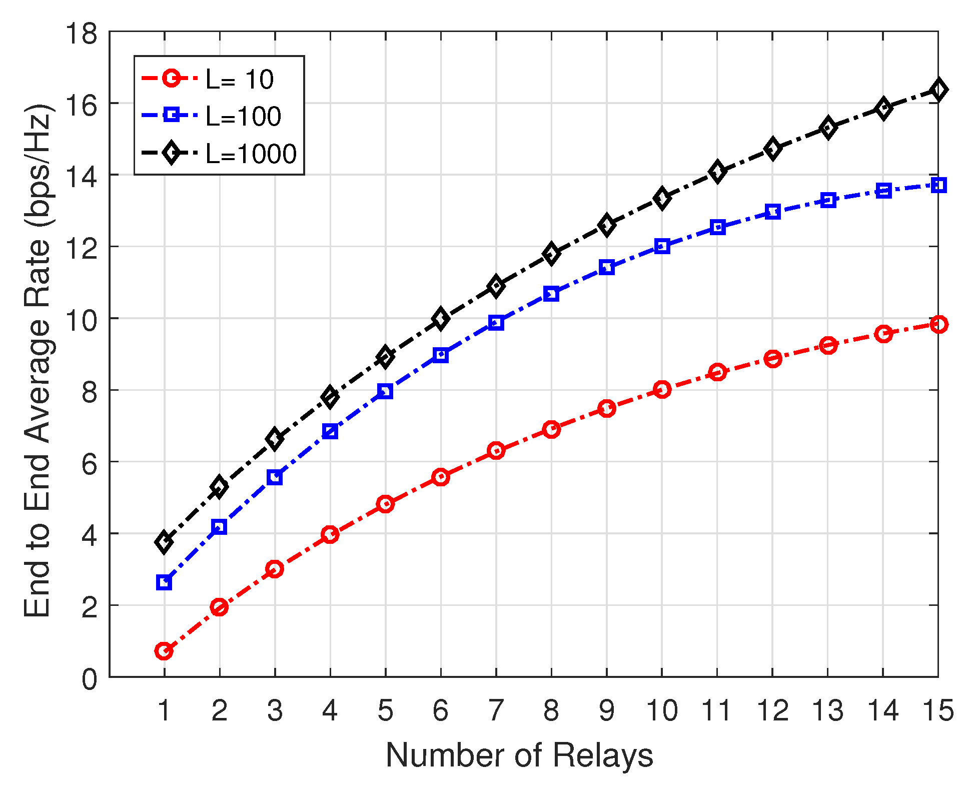
Figure 13.
Outage probability vs. the number of relays.
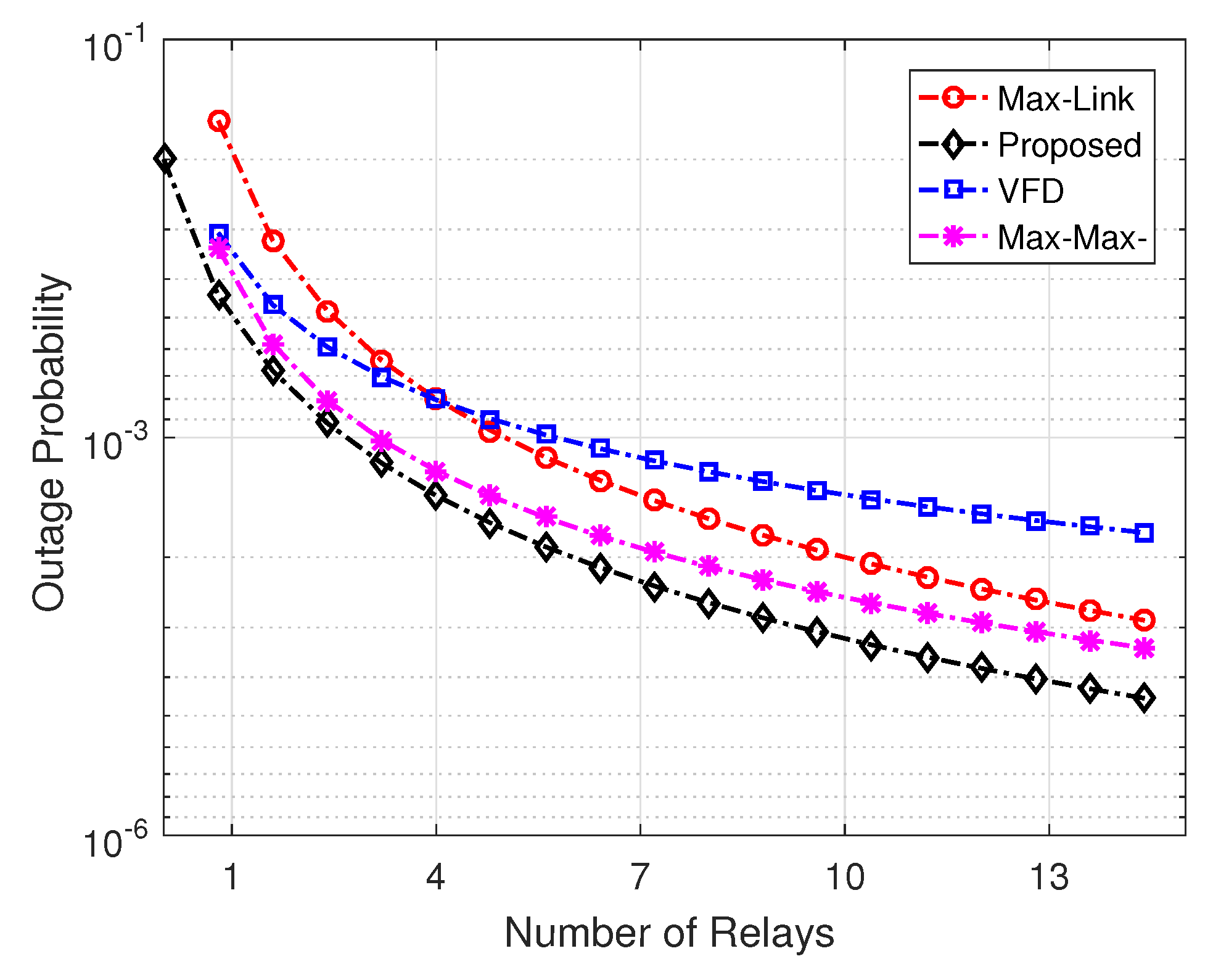
Figure 14.
Average data rate vs. SNR.

Figure 15.
Outage probability vs. SNR.

Figure 16.
Average throughput vs. SNR.

Figure 17.
Average delay vs. SNR.
© 2019 by the authors. Licensee MDPI, Basel, Switzerland. This article is an open access article distributed under the terms and conditions of the Creative Commons Attribution (CC BY) license (http://creativecommons.org/licenses/by/4.0/).
Share and Cite
MDPI and ACS Style
Alvi, S.A.; Hussain, R.; Hasan, Q.U.; Malik, S.A. Improved Buffer-Aided Multi-Hop Relaying with Reduced Outage and Packet Delay in Cognitive Radio Networks. Electronics 2019, 8, 895. https://doi.org/10.3390/electronics8080895
AMA Style
Alvi SA, Hussain R, Hasan QU, Malik SA. Improved Buffer-Aided Multi-Hop Relaying with Reduced Outage and Packet Delay in Cognitive Radio Networks. Electronics. 2019; 8(8):895. https://doi.org/10.3390/electronics8080895
Chicago/Turabian StyleAlvi, Shakeel Ahmed, Riaz Hussain, Qadeer Ul Hasan, and Shahzad Ali Malik. 2019. "Improved Buffer-Aided Multi-Hop Relaying with Reduced Outage and Packet Delay in Cognitive Radio Networks" Electronics 8, no. 8: 895. https://doi.org/10.3390/electronics8080895
Note that from the first issue of 2016, this journal uses article numbers instead of page numbers. See further details here.