Article

A Signaling-Free Underwater Code Division Multiple Access Scheme

School of Electronics Engineering, Kyungpook National University, Daegu 41566, Korea
*
Author to whom correspondence should be addressed.
Electronics 2019, 8(8), 880; https://doi.org/10.3390/electronics8080880
Submission received: 17 June 2019 / Revised: 24 July 2019 / Accepted: 6 August 2019 / Published: 8 August 2019
(This article belongs to the Special Issue Underwater Communication and Networking Systems)

Abstract

:
In this paper, we propose an underwater code division multiple access system where each sensor node independently evaluates whether a channel is available or not without control message exchanges with a central data-gathering node named a sink. A sensor node is able to estimate how large power is currently received at a sink in the distance based on the overheard power at the node from neighbors. If the estimated power is below a certain threshold level, the sensor node is allowed to transmit data in a p-persistent manner, where the probability p depends on the available capacity. Simulation results show the traffic estimation works well as demonstrated by a success probability of approximately 100%, and the data throughput improves in most of the offered traffic region because of the removal of the control signaling related to channel allocation.

1. Introduction

There has been growing demand for underwater acoustic sensor networks for various military and commercial applications including oceanographic data collection, environmental monitoring, resource investigation, disaster prevention, undersea exploration, assisted navigation, distributed tactical surveillance, and mine reconnaissance [1]. To successfully implement these applications, it is important to understand the characteristics of the underwater communication channel and thus design a methodology for communication between the sensor nodes. Previous studies have found that using an acoustic signal is the most suitable approach to transport information in an underwater communications channel [2].
However, acoustic signals have poor characteristics in underwater communication channels, such as a low propagating speed of 1500 m/s, which is five orders of magnitude lower than the terrestrial radio propagation speed, limited available bandwidth, multipath fading, temporary losses of connectivity (shadow zone), and Doppler spread [1,3,4]. Therefore, underwater communication suffers from a high bit error rate and long propagation delays. Enhancements or modifications for an underwater environment in terms of modulation schemes and medium access control (MAC) protocols are required to overcome the harsh underwater channel conditions.
Code division multiple access (CDMA) is a promising underwater MAC scheme and has been intensely studied because of its advantages such as robustness against frequency-selective fading and high frequency-reuse efficiency [5,6]. Thus, the CDMA studies have been mainly focused on spread code assignment, power control, and energy efficiency [7,8,9,10,11]. In [12,13], code assignment and power control schemes for a transmitter-based CDMA system were proposed to achieve high network throughput, low energy consumption, and limited channel access delay in deep underwater communications. In [14], a path-oriented code assignment (POCA)-CDMA-MAC protocol was proposed to resolve the funneling effect in multi-hop underwater acoustic sensor networks where the sink discriminates data arriving from multiple routing-paths simultaneously by assigning each path a distinct spreading sequence.
However, most CDMA systems employ a signaling procedure between the sink and sensor nodes to exchange control messages involved in power control, channel access, etc. Owing to the very limited bandwidth of acoustic channels and long propagation delays, the overhead of the signaling procedure causes severe deterioration in performance in terms of throughput and latency. Although there have been several works for freeing signaling procedure in MAC protocols, they are restricted to ALOHA- and CSMA (Carrier Sense Multiple Access)-family protocols [15,16,17]. In [18], the ALOHA with carrier sensing (ALOHA-CS) is proposed using a new back-off window to adapt the protocol to variable propagation delay. Similarly, to improve medium access opportunity, CSMA-ALOHA [19] adopts a random sensing duration shorter than the time required for the signal to propagate over the sensing range. However, to the best of our knowledge, the effort to remove the signaling overhead in CDMA has not been made for underwater environments.
In this paper, we propose an underwater CDMA without any signaling procedure related to channel access and power control. Individual sensor nodes evaluate channel availability by estimating the number of nodes currently communicating with the sink, based on individual power measurement. If the estimated number of nodes is less than the system capacity, then the node tries to occupy the channel in a p-persistent manner. The estimation is mathematically driven and evaluated by computer simulation. Numerical results show that the hit probability of this estimation is almost one, and system performance is significantly improved in terms of throughput.

2. An Overview of the Characteristics of the Underwater Channel and System Model

2.1. The Characteristics of the Underwater Channel

In this paper, we consider Thorp’s underwater channel model [1], the most widely used underwater channel model, which derives the signal attenuation depending on the frequency and the distance. It also derives the underwater ambient noise power spectral density depending on the frequency. Frequency and the distance between transmitter and receiver mainly determine the attenuation of an acoustic wave. Hence, the overall attenuation can be expressed as a function of the frequency and distance, which is given by
A ( l , f ) = A 0 l k a ( f ) l
where l is a distance between the transmitter and the receiver (km), f is signal frequency (kHz), A 0 is the normalizing constant, and k is the spreading factor. The spreading factor has a value between one and two depending on the depth. k = 1 indicates a cylindrical spreading that characterizes shallow water communication, and k = 2 indicates a spherical spreading that characterizes deep water communication. In general, k = 1.5 is often considered as a practical spreading value. Therefore, we assume the spreading factor as 1.5 and the normalizing constant as 30 dB. We note that these values reflect the characteristics of a quiet, deep sea [20]. a ( f ) is the absorption coefficient and is expressed in dB/km for f in kHz:
10 log a ( f ) = 0.11 f 2 1 + f 2 + 44 f 2 4100 + f 2 + 2.75 × 10 4 f 2 + 0.003
This equation is generally valid for frequencies above a few hundred Hz. For lower frequencies, the following formula may be used:
10 log a ( f ) = 0.002 + 0.11 f 2 1 + f 2 + 0.011 f 2

2.2. System Model

We considered a data gathering CDMA network with a star topology, where the sink is located at the center and sensor nodes in charge of data-sensing and reporting are uniformly distributed over an ideal circle-shaped coverage. It is assumed that each sensor node acquires the distance to the sink and the unique orthogonal code for CDMA communication through the network initialization stage, in which measurement of round-trip time and orthogonal code allocation take place. Based on Thorp’s underwater channel model, sensor nodes are able to control transmission power with the knowledge of the distance and the frequency, in such a way that regardless of their locations, the received power at the sink is equal to a specific level.

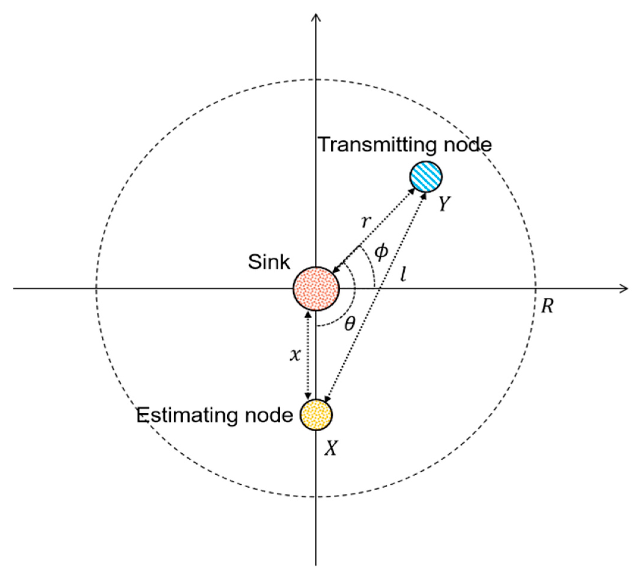
3. Estimating the Number of Nodes in Transmission

As shown in Figure 1, suppose that node X, located at a distance x from the sink, is examining the channel availability for data transmission while node Y is transmitting. For mathematical description simplicity, using polar coordinates, we locate the sink at the origin (0, 0), node X at ( x , π 2 ) , and node Y at ( r , ϕ ) . Let θ and l denote the angle and distance between node X and Y, respectively. Let P Y t denote the transmission power at node Y and P S r c v denote the common received power at sink then,
P Y t B A 1 ( r , f ) d f = P S r c v = S ( f ) B
where S ( f ) represent the common received power spectral density at the sink. We assume that S ( f ) is flat for f B where B is a signal bandwidth. Therefore, the transmission power at node Y is given by
P Y t = S ( f ) B B A 1 ( r , f ) d f
In a similar manner, the received power at node X when node Y is transmitting is
P X Y r c v = P Y t B A 1 ( l , f ) d f
Because P X Y r c v is obtained from the specific location of node Y with r and θ , over the whole region with radius R, we can obtain the expected value of received power at node X from a node Y:
E [ P X Y r c v ] = 0 R 0 2 π P X Y r c v f r , Θ ( r , θ ) d θ d r = 0 R 0 2 π P X Y r c v f r ( r ) f Θ ( θ ) d θ d r = 0 R 0 2 π P X Y r c v 2 r R 2 1 2 π d θ d r
where f r , Θ ( r , θ ) , f r ( r ) , and f Θ ( θ ) represent the joint probability density functions of r and θ , the probability density function of r, and the probability density function of θ , respectively. We assume that f r , Θ ( r , θ ) is uniformly distributed over the cell with radius R. Because E [ P X Y r c v ] corresponds to the value for one node Y, the value is multiplied when multiple nodes are transmitting and accordingly, the number of transmitting nodes is estimated in a way that the measured receiving power at node X becomes closest to the certain multiple times of E [ P X Y r c v ] like
N e = ( min | P X r c v n E [ P X Y r c v ] | ) n arg
where P X r c v denotes the measured receiving power at node X.

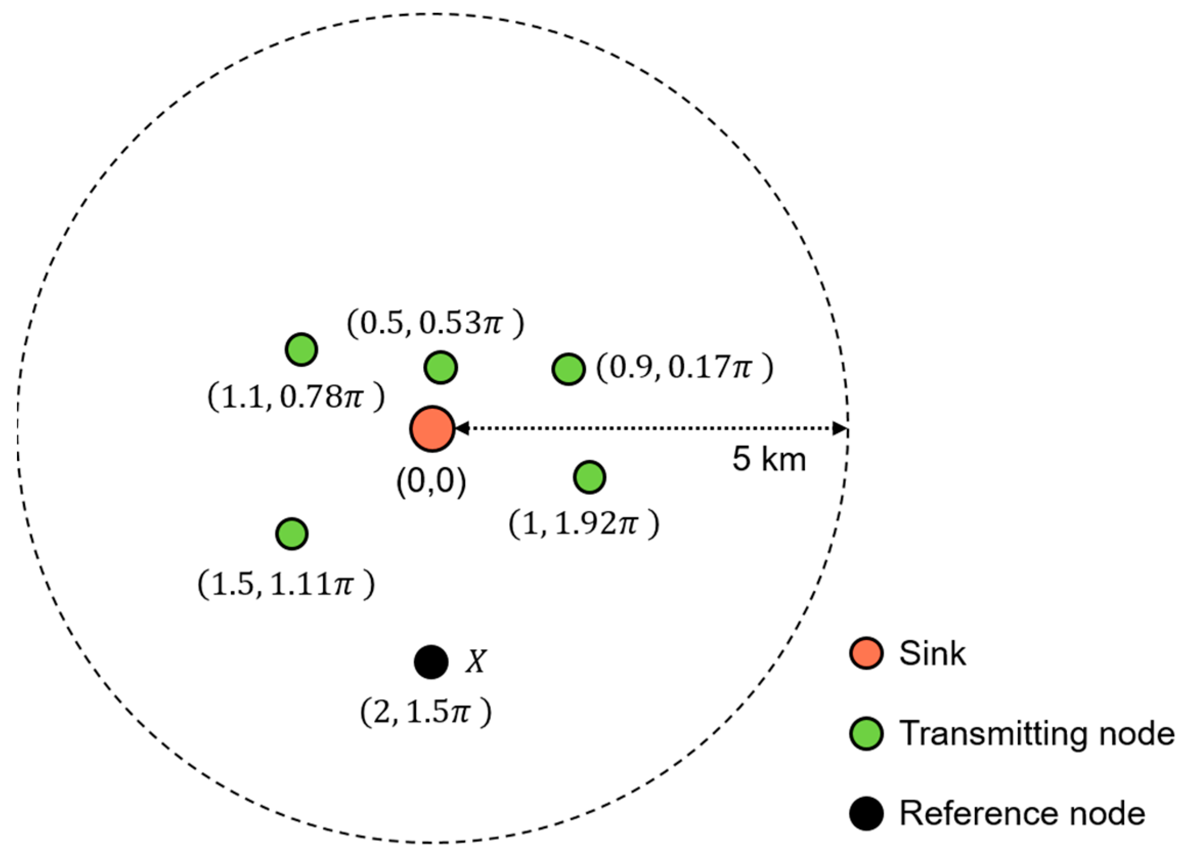
4. An Example of Traffic Estimation

Figure 2 illustrates a topological scenario as an example for which the proposed scheme is applied. The reference node X indicates who is trying to estimate the number of transmitting nodes and is located at ( 2 , 1.5 π ) in polar coordinates, and the other five nodes are randomly located. Let us say that S ( f ) B is 81 dB re 1 μpa (i.e., the power associated with the reference sound pressure level of 1 μpa). We note that this value is chosen based on the range of the power spectral density of ambient underwater noise, which is from 60 to 100 dB re 1 μpa/Hz [4]. Then, the expectation E [ P X Y r c v ] is calculated to be 67 dB re 1 μpa using Equation (7). Meanwhile, the measured receiving power at node X, P X r c v , which depends on the node distribution, is ≈74 dB re 1 μpa. Then, the reference node X finds the number of nodes, n, such that the difference between n E [ P X Y r c v ] and P X r c v is minimized, as described in Equation (8). The procedure to find N e is summarized in Table 1, where N e is found to be 5, which is equal to the number of transmitting nodes in the example of Figure 2, and thus the estimation is correct.

5. Probabilistic Channel Access

We assumed that the system has a predefined CDMA system capacity—the number of nodes that are allowed to transmit simultaneously—which we denote as C. The nodes examining the channel availability estimate the number of currently transmitting nodes N e (obtained by Equation (8)). If N e is less than C, then the examining nodes are allowed to join the transmission. However, if they try immediate joining, it may cause overflow—total number of transmitting nodes including the newly joining nodes exceeds the capacity C. Therefore, a probabilistic channel access in a p-persistent manner is employed to avoid such overflow. The channel access probability is proportional to the availability of the channel and is given by
p t r = { C N e C ,   C > N e 0 ,   otherwise
where P t r = 0 means the transmission is delayed by a random back-off and restarts from the beginning, i.e., channel estimation.

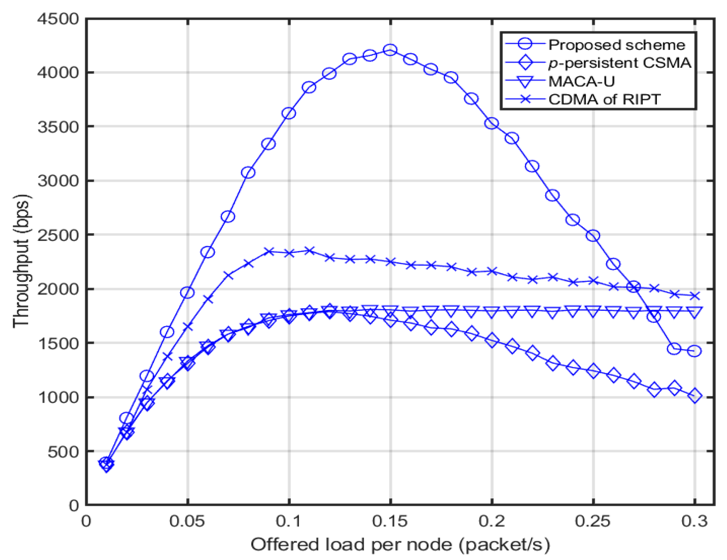
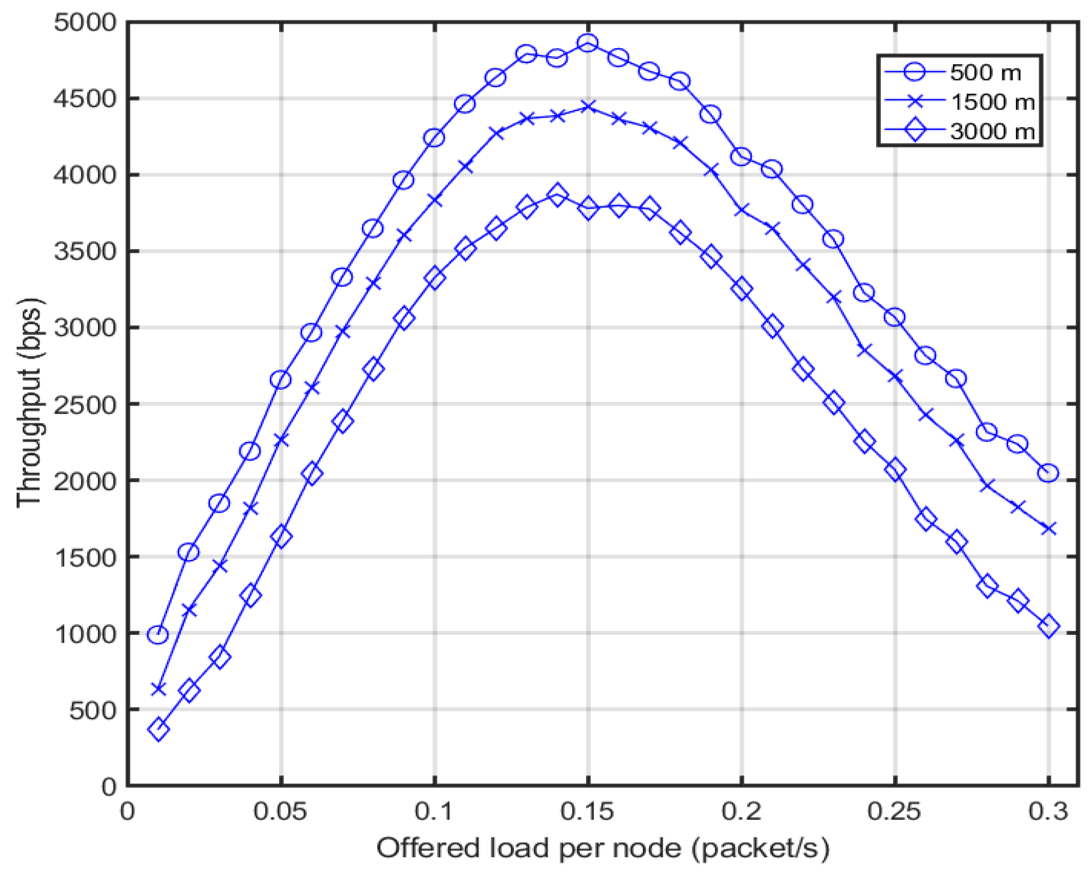
6. Performance Evaluation

As comparing schemes, we considered whether or not a signaling procedure is present, and whether or not it is CDMA-based, and we chose from three schemes: p-persistent CSMA, MACA-U [12], and CDMA, using a four-way handshake of RIPT protocol [21]. Table 2 categorizes the schemes. In the CDMA of RIPT protocol, the sink broadcasts ready-to-receive (RTR) packets to invite sensor nodes that are willing to transmit data packets. Having gathered the responses (RTP: Ready-to-participate) from the sensor nodes, the sink lists the sensor nodes that are served within CDMA capacity and replies to them with an ORDER packet. Reading the ORDER packets, the sensor nodes that are included in the list transmit their data packets. The operation of CDMA of RIPT protocol is illustrated in Figure 3.
A data packet is generated at each node to follow the Poisson process at the rate of λ (packet/sec). To cope with traffic congestion, all schemes are assumed to employ the binary exponential random back-off specified in the IEEE 802.11 standard [23]. Packet losses are only caused by collisions, not by physical channel deterioration such as noise and multipath fading. Table 3 summarizes the system parameters used in the computer simulation. The data rate in Table 3 corresponds to the multiplexed one, i.e., in the case of CDMA with a capacity of four, each channel has a data rate of 2400 bps. We averaged the results of 1000 times iteration for each parameter to derive the result.
During packet generation, the sensor node measures receiving power based on the estimated number of nodes currently transmitting packets to the sink. Because the transmission power of a sensor node is controlled not to extend far beyond the sink, in the case where the estimating node is located at the opposite side from the transmitting nodes, the received power may not be adequate for correct estimation. However, even with such a difficult condition in the simulation, the successful traffic estimation ratio is maintained above 95% for almost all cases of offered load as shown in Figure 4.
Figure 5 shows the throughput varying the offered load per node. Throughput is defined as the number of data bits successfully received at the sink per second from all sensor nodes. The throughput of the proposed system is shown to be much higher than the comparing schemes for almost cases of the offered load. It proves that the channel access without signaling procedure works well, significantly reducing both the signaling overhead and the associated delay. An issue that we need to resolve is that as the offered load gets heavier, the throughput of the proposed scheme degrades rapidly, and even falls below CDMA of RIPT and MACA-U at over 0.25 offered load. This might be an extremely heavy traffic condition related to various monitoring-related applications [25]. The reason for this is that while the signaling-based schemes like CDMA of RIPT and MACA-U can prevent throughput from decreasing below a certain level using a channel reservation, as traffic load increases the proposed system, this shows excessive caution for transmission and keeps delaying it because the estimated traffic mostly exceeds capacity. Therefore, the probability of transmission p t r needs to be adjusted for the special case of heavy traffic. This is not dealt with in this paper but remains as a potential future work.
Regarding the fairness for channel occupation, in signaling-assisted protocols such as MACA-U and CDMA of RIPT, the nodes closer to the sink are more probably occupying the channel because the channel reservation control message such as RTS may arrive earlier at the sink than from the nodes far away from the sink. In contrast, the proposed scheme equally gives the opportunity for channel occupation independently of the nodes’ location because any node finding an available channel is allowed to occupy the channel.
Figure 6 shows the throughput of sensor nodes in relation to the location from the sink. As the node gets farther from the sink, the traffic estimation may be incorrect because the received power from the other nodes is probably not strong enough. Especially when other nodes are mostly located at the opposite side beyond the sink, the node is probably blind to their existence and accordingly, underestimates the number of nodes. Such a wrong estimation causes collisions at the sink and thus the throughput decreases. Meanwhile, the node closer to the sink is able to catch all the power transmitted from any location inside the cell and thus is able to estimate the traffic more precisely.

7. Conclusions

In this paper, we proposed a CDMA scheme that removes signaling overhead associated with channel access and thereby increases throughput along with reducing delay. Sensor nodes are able to correctly estimate the number of nodes in transmission only by means of received power measurement. Computer simulation shows that the ratio of successful traffic estimation is above 95% for varied offered load conditions. With reference to throughput, the proposed scheme outperforms the schemes against which it was compared for almost all cases of offered load. We note that the proposed scheme can be implemented and evaluated in a real underwater environment. Underwater nodes consist of a commercial underwater modem and a DSP board where we can program the proposed MAC protocol algorithm. Then, each node is deployed in the underwater environment to build an underwater star topology network. After deployment, each node executes the MAC protocol operation and maintains a log of the events. Using the MAC protocol event logs, the performance of the proposed scheme can be evaluated. In a future study, the persistent transmission probability p t r will be researched to make the proposed scheme more sustainable regardless of traffic conditions.

Author Contributions

B.-M.S. performed computer simulations and wrote the paper, J.C. participated in data analysis and revision process. H.-S.C. supervised the research and participated in problem formulation, data analysis and revision process.

Funding

This research was supported by the project titled “Development of Distributed Underwater Monitoring &Control Networks”, funded by the Ministry of Oceans and Fisheries, Korea.

Conflicts of Interest

The authors declare no conflict of interest.

References

  1. Akyildiz, I.F.; Pompili, D.; Melodia, T. Underwater acoustic sensor networks: Research challenges. Ad Hoc Netw. 2005, 3, 257–279. [Google Scholar] [CrossRef]
  2. Xavier, L. An Introduction to Underwater Acoustics: Principles and Application; Springer Verlag: Berlin, Germany, 2010. [Google Scholar]
  3. Stojanovic, M.; Preisig, C.J. Underwater acoustic communication channels: Propagation models and statistical characterization. IEEE Commun. Mag. 2009, 47, 84–89. [Google Scholar] [CrossRef]
  4. Stojanovic, M. On the Relationship between Capacity and Distance in an Underwater Acoustic Communication Channel. In Proceedings of the First ACM International Workshop on Underwater Networks (WUWNet 2006), Los Angeles, CA, USA, 25 September 2006; pp. 41–47. [Google Scholar]
  5. Cui, J.-H.; Kong, J.; Gerla, M.; Zhou, S. Challenges: Building scalable mobile underwater wireless sensor networks for aquatic applications. IEEE Netw. Spec. Issue Wirel. Sens. Netw. 2006, 20, 12–18. [Google Scholar]
  6. Sozer, E.; Proakis, J.; Stojanovic, M.; Rice, J.; Benson, A.; Hatch, M. Direct Sequence Spread Spectrum Based Modem for Underwater Acoustic Communication and Channel Measurements. In Proceedings of the MTS/IEEE OCEANS ’99, Seattle, WA, USA, 13–16 September 1999; pp. 228–233. [Google Scholar]
  7. Nie, D.; Feng, Y.; Zhen, C.; Zhang, J.; Ning, G. Power control for underwater acoustic MC-CDMA communication networks using the improved PSO algorithm. In Proceedings of the MTS/IEEE OCEANS ’16, Shanghai, China, 10–13 June 2016; pp. 1–4. [Google Scholar]
  8. Zhen, C.; Feng, Y.; Nie, D.; Zhang, J.; Ning, G. Transmission power allocation for underwater acoustic multicarrier-CDMA communication networks based on genetic algorithm. In Proceedings of the MTS/IEEE OCEANS ’16, Shanghai, China, 10–13 June 2016; pp. 1–4. [Google Scholar]
  9. Arifeen, M.M.; Tasnim, Z.; Mahmud, M.; Kaiser, M.S. Performance Analysis of MC-CDMA based Underwater Wireless Sensor Network. In Proceedings of the ICACCI 2018, Bangalore, India, 19–22 September 2018; pp. 1919–1924. [Google Scholar]
  10. Jia, Z.; Yuan, F.; Chen, K.; Cheng, E.; Li, J. Research on Code Division Multiple Access Based on Chirp Multi-Carrier. In Proceedings of the MTS/IEEE OCEANS ’18, Kobe, Japan, 28–31 May 2018; pp. 1–6. [Google Scholar]
  11. Rahmati, M.; Pompili, D.; Petroccia, R. Collaborative Hybrid ARQ for CDMA-based Reliable Underwater Acoustic Communications. In Proceedings of the Underwater Communications and Networking (Ucomms) 2018, Lerici, Italy, 28–30 August 2018; pp. 1–5. [Google Scholar]
  12. Shengming, J. State-of-the-Art Medium Access Control (MAC) Protocols for Underwater Acoustic Networks: A Survey Based on a MAC Reference Model. IEEE Commun. Surv. Tutor. 2018, 20, 96–131. [Google Scholar]
  13. Pompili, D.; Melodia, T.; Akyildiz, I.F. A CDMA-based medium access control for underwater acoustic sensor networks. IEEE Trans. Wirel. Commun. 2009, 8, 1899–1909. [Google Scholar] [CrossRef]
  14. Chen, H.; Fan, G.; Xie, L.; Cui, J.-H. A Hybrid Path-Oriented Code Assignment CDMA-based MAC Protocol for Underwater Acoustic Sensor Networks. Sensors 2013, 13, 15006–15025. [Google Scholar] [CrossRef] [PubMed]
  15. Park, S.H.; Mitchell, P.D.; Grace, D. Performance of the ALOHA-Q MAC Protocol for Underwater Acoustic Networks. In Proceedings of the International Conference on Computing, Electronics & Communications Engineering (iCCECE) 2018, Southend, UK, 16–17 August 2018; pp. 189–194. [Google Scholar]
  16. Geethu, K.S.; Babu, A.V. Improving energy efficiency performance of ALOHA based underwater acoustic sensor networks. In Proceedings of the IEEE Distributed Computing, VLSI, Electrical Circuits and Robotics (DISCOVER) 2016, Mangalore, India, 13–14 August 2016; pp. 277–282. [Google Scholar]
  17. Khater, E.M.; Ibrahim, D.M.; Saidahmed, M.T.F. Contention-based MAC protocol in UWSNs: Slotted_CS_ALOHA proposed protocol. In Proceedings of the 11th International Conference on Computer Engineering & Systems (ICCES), Cairo, Egypt, 20–21 December 2016; pp. 73–78. [Google Scholar]
  18. Guerra, F.; Casari, P.; Zorzi, M. World ocean simulation system (WOSS): A simulation tool for underwater networks with realistic propagation modeling. In Proceedings of the ACM Int. Workshop Underwater Netw. (WUWNet), Berkeley, CA, USA, 3 November 2009; pp. 1–8. [Google Scholar]
  19. Favaro, F.; Azad, S.; Casari, P.; Zorzi, M. Extended abstract: On the performance of unsynchronized distributed MAC protocols in deep water acoustic networks. In Proceedings of the ACM Int. Workshop Underwater Netw. (WUWNet), Seattle, WA, USA, 1–2 December 2011; pp. 1–2. [Google Scholar]
  20. Jornet, J.M.; Stojanovic, M.; Zorzi, M. On Joint Frequency and Power Allocation in a Cross-Layer Protocol for Underwater Acoustic Networks. IEEE J. Ocean. Eng. 2010, 35, 936–947. [Google Scholar] [CrossRef]
  21. Chirdchoo, N.; Soh, W.S.; Chua, K. RIPT: A receiver-initiated reservation-based protocol for underwater acoustic networks. IEEE J. Sel. Areas Commun. 2005, 26, 1744–1753. [Google Scholar] [CrossRef]
  22. Ng, H.-H.; Soh, W.-S.; Motani, M. MACA-U: A Media Access Protocol for Underwater Acoustic Networks. In Proceedings of the IEEE Globecom 2008, New Orleans, LA, USA, 30 November–4 December 2008; pp. 1–5. [Google Scholar]
  23. LAN/MAN (IEEE 802) Standards Committee. Wireless LAN Media Access Control (MAC) and Physical Layer (PHY) Specifications; IEEE: New York, NY, USA, 1999. [Google Scholar]
  24. LinkQuest Inc. Available online: http://www.link-quest.com (accessed on 12 November 2018).
  25. Su, R.; Venkatesan, R.; Li, C. An energy-efficient asynchronous wake-up scheme for underwater sensor networks. Wirel. Commun. Mob. Comput. 2015, 16, 1158–1172. [Google Scholar] [CrossRef]
Figure 1. Nodes’ locations.
Electronics 08 00880 g001
Figure 2. A topological scenario as an example for traffic estimation.
Electronics 08 00880 g002
Figure 3. Operation of CDMA of RIPT protocol.
Electronics 08 00880 g003
Figure 4. Success rate of traffic estimation.
Electronics 08 00880 g004
Figure 5. Throughput for proposed scheme with other MAC protocols.
Electronics 08 00880 g005
Figure 6. Throughput of the node at different distances from the sink.
Electronics 08 00880 g006
Table 1. Parametric values generated during traffic estimation for the example of Figure 2.
n123456
E [ P X Y r c v ]
(dB re 1 μpa)
67
n E [ P X Y r c v ]
(dB re 1 μpa)
677071737475
| P X r c v n E [ P X Y r c v ] |
(dB re 1 μpa)
7372706862
(minimum)
65
N e 5
Table 2. Categorization of proposed and comparing scheme.
Signaling-FreeSignaling-Based
CDMAProposed schemeCDMA of RIPT [21]
Non-CDMAp-persistent CSMAMACA-U [22]
Table 3. System parameters and values.
ParametersValues
Data rate9600 bps [24]
Data packet size2000 bits
Control packet size200 bits
CDMA system capacity (C)4
Spreading gain6 dB
Number of sensor nodes20
Radius of topology (R)
Number of transmitting node
Acoustic speed
5 km
20
1500 m/s
Bandwidth20 kHz
Center frequency15 kHz
Transmission probability of CSMA (p)
Simulation time
0.5
3600 s

