A Telemetry, Tracking, and Command Antennas System for Small-Satellite Applications

 ,
,  ,
,  , and
, and 
Abstract
:1. Introduction
2. Antennas System
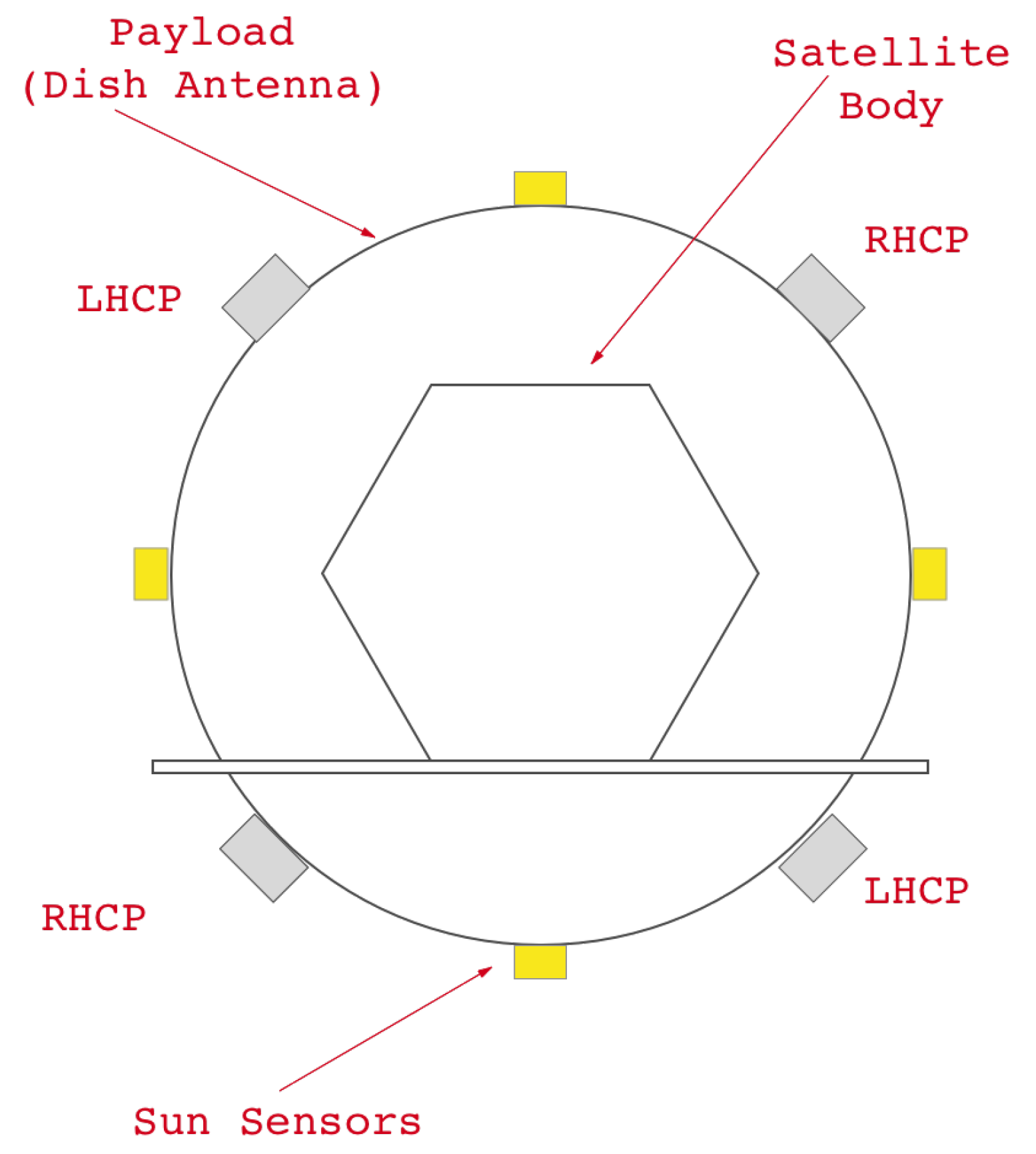
2.1. Configuration
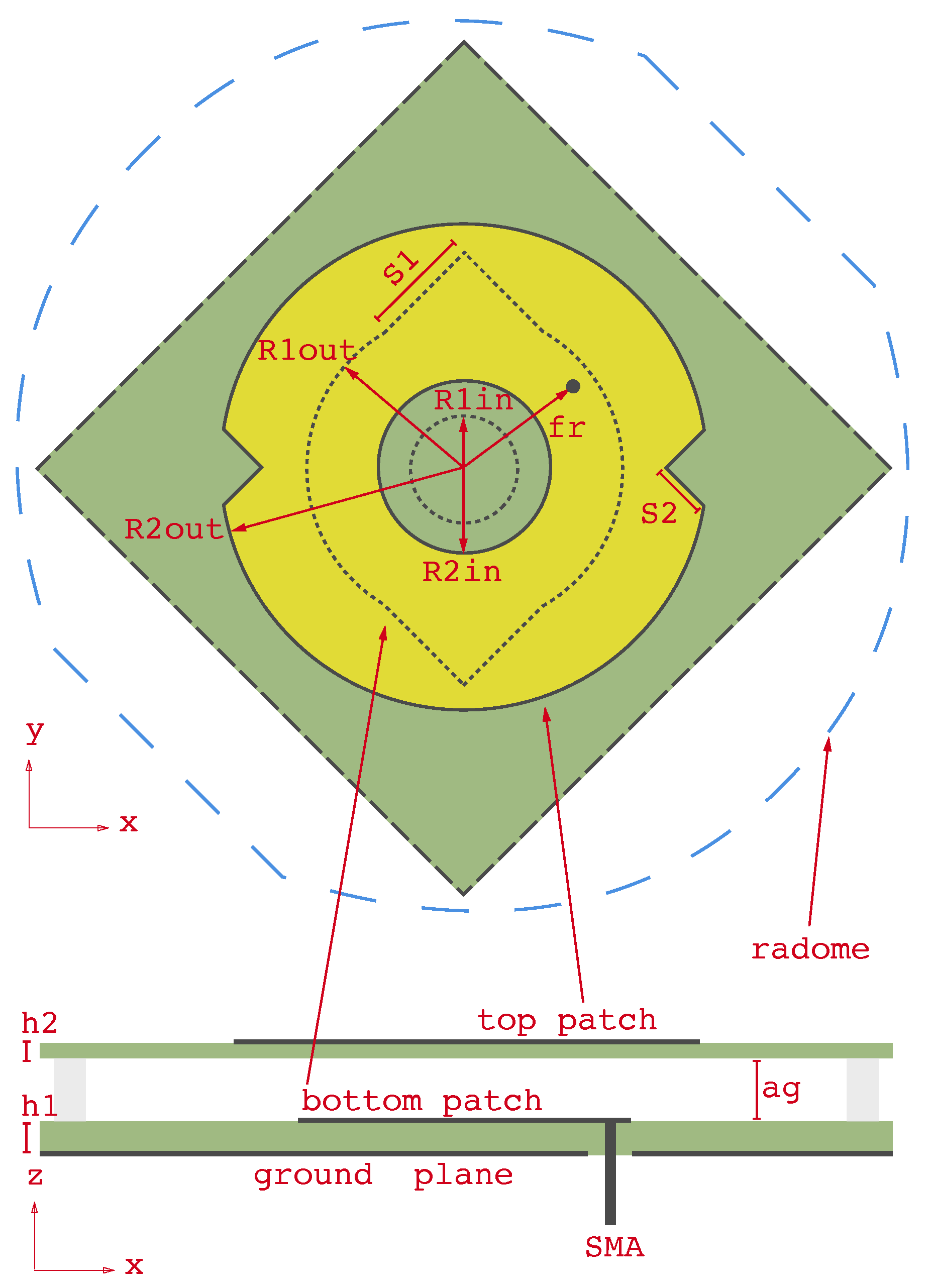
2.2. Antenna Element
3. Parametric Study
3.1. Triangular Extensions and Slits
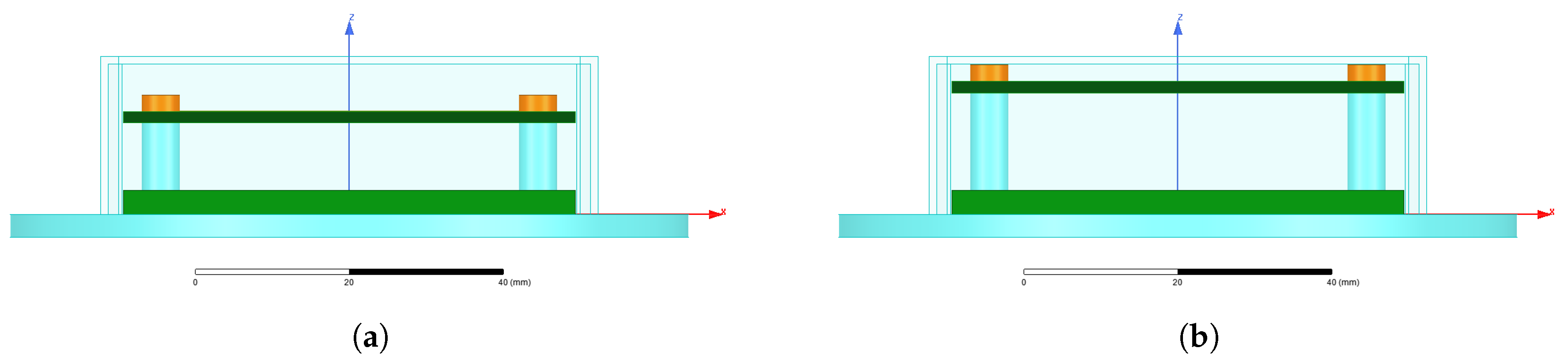
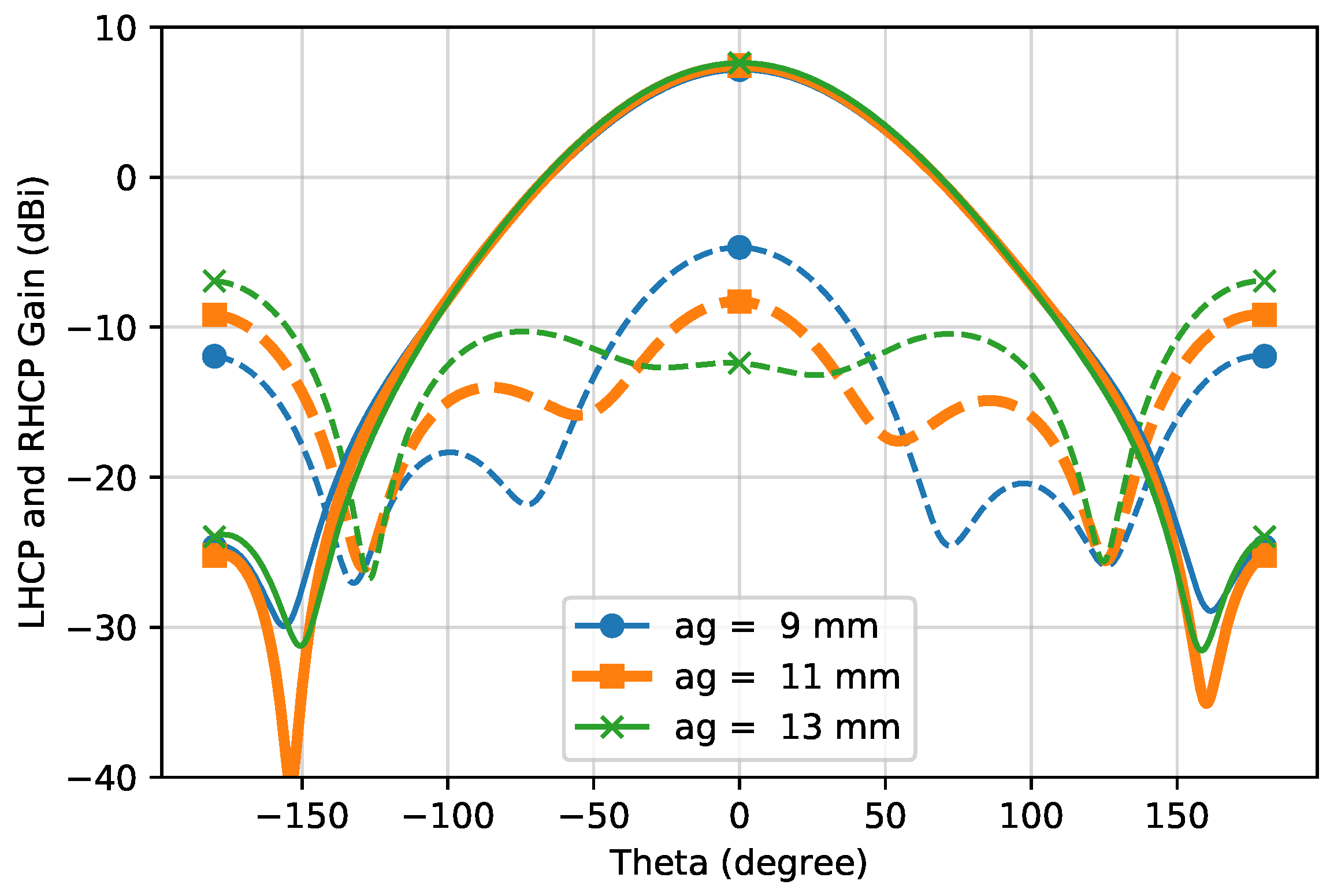
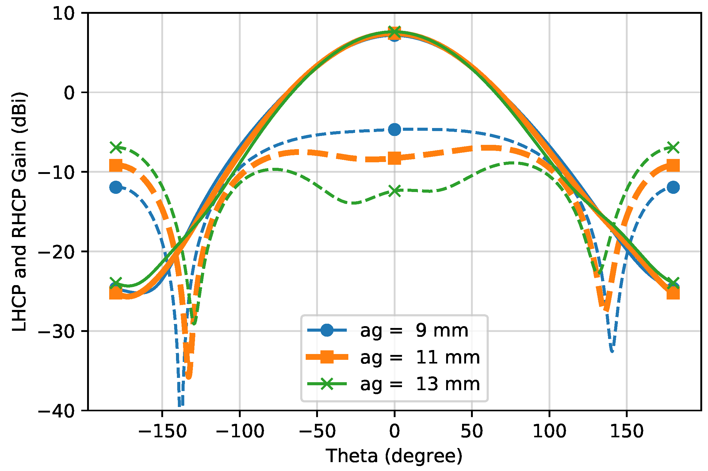
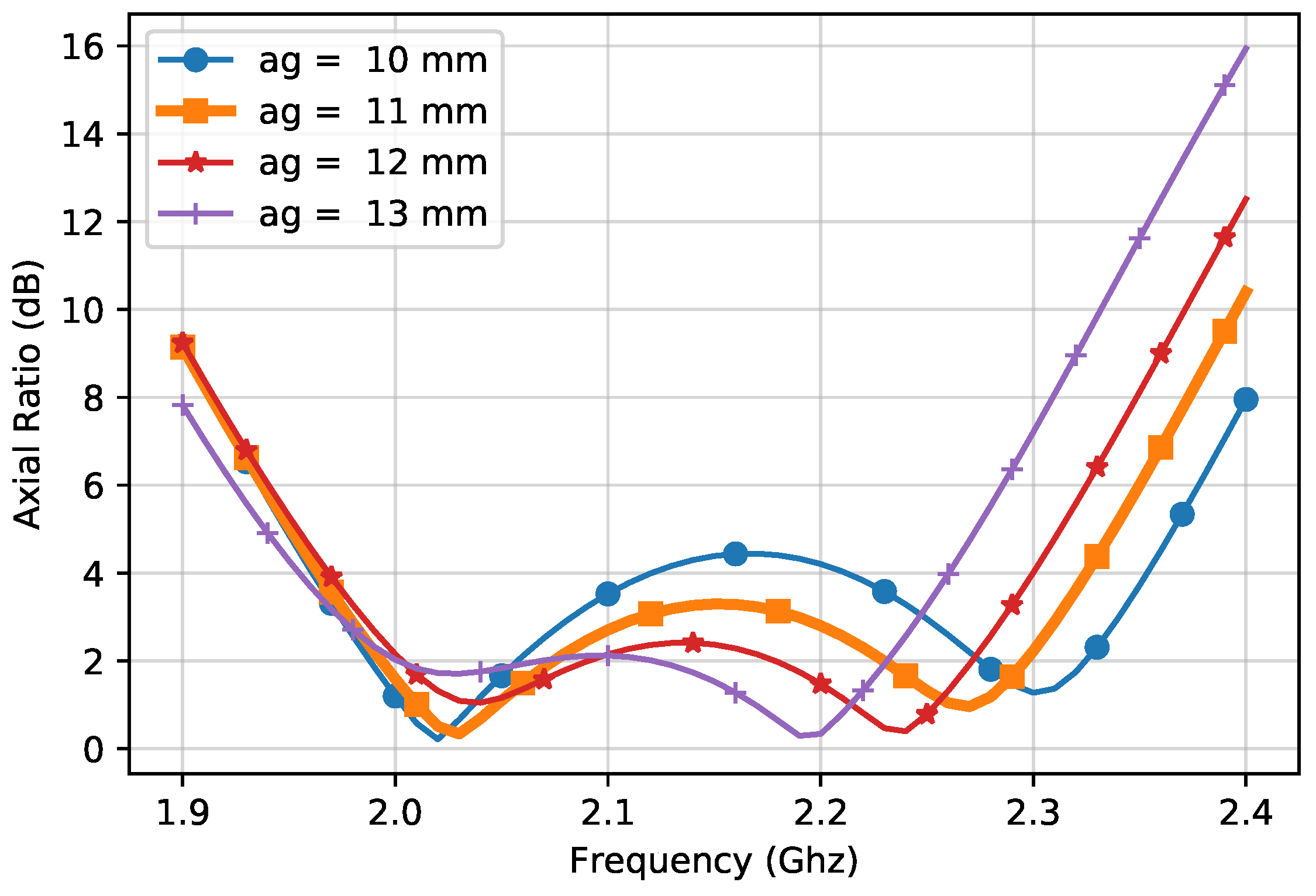
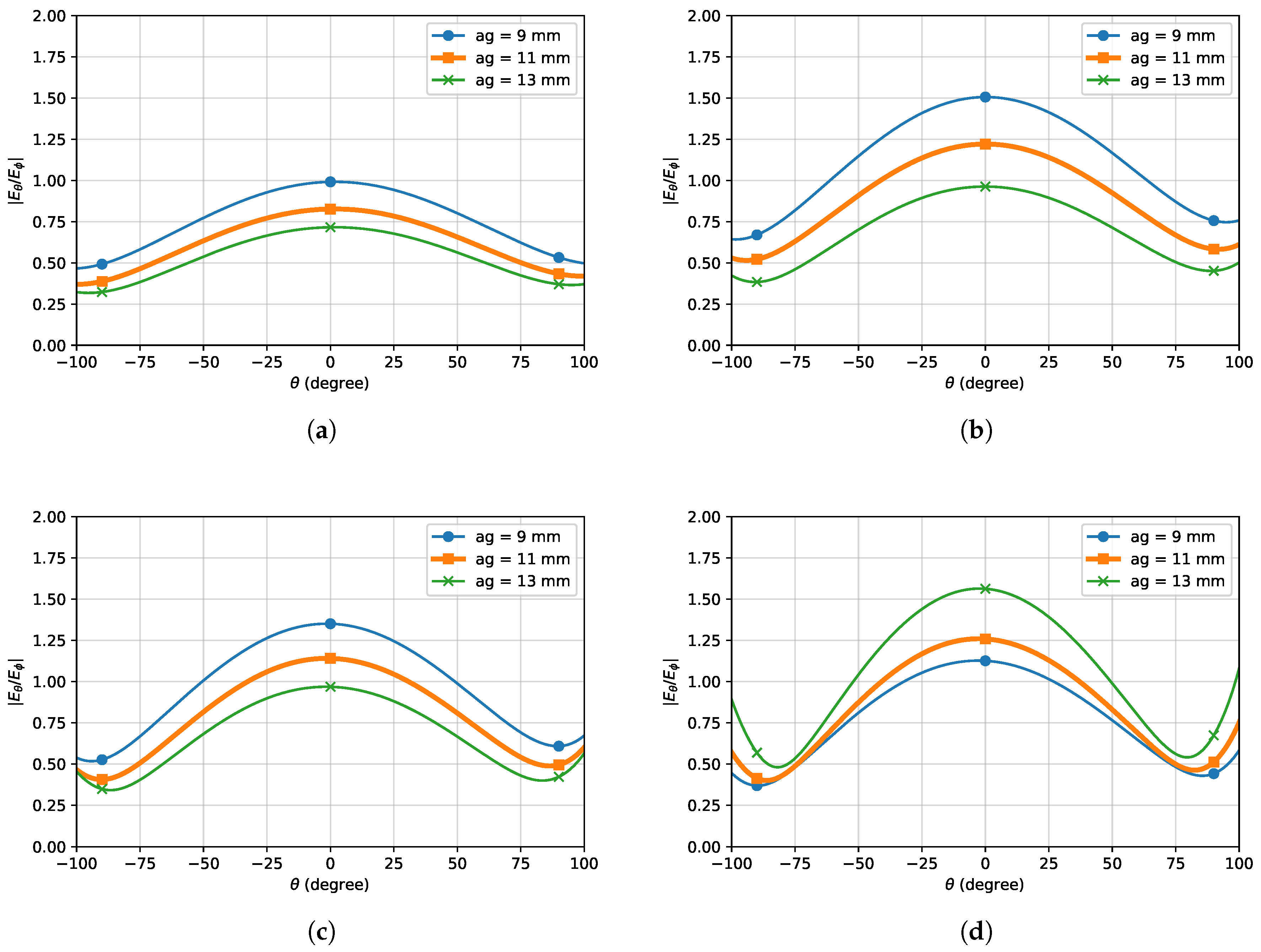
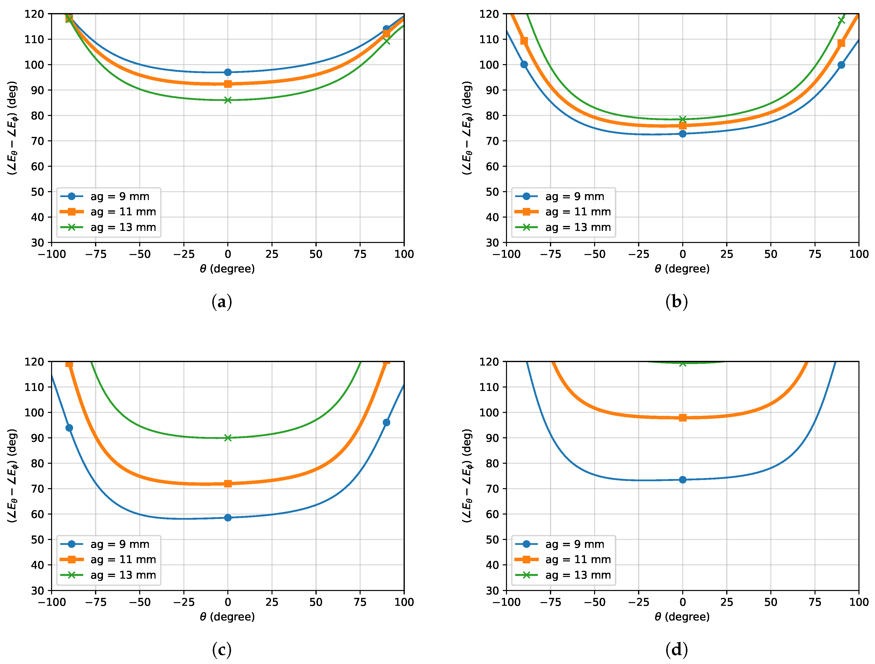
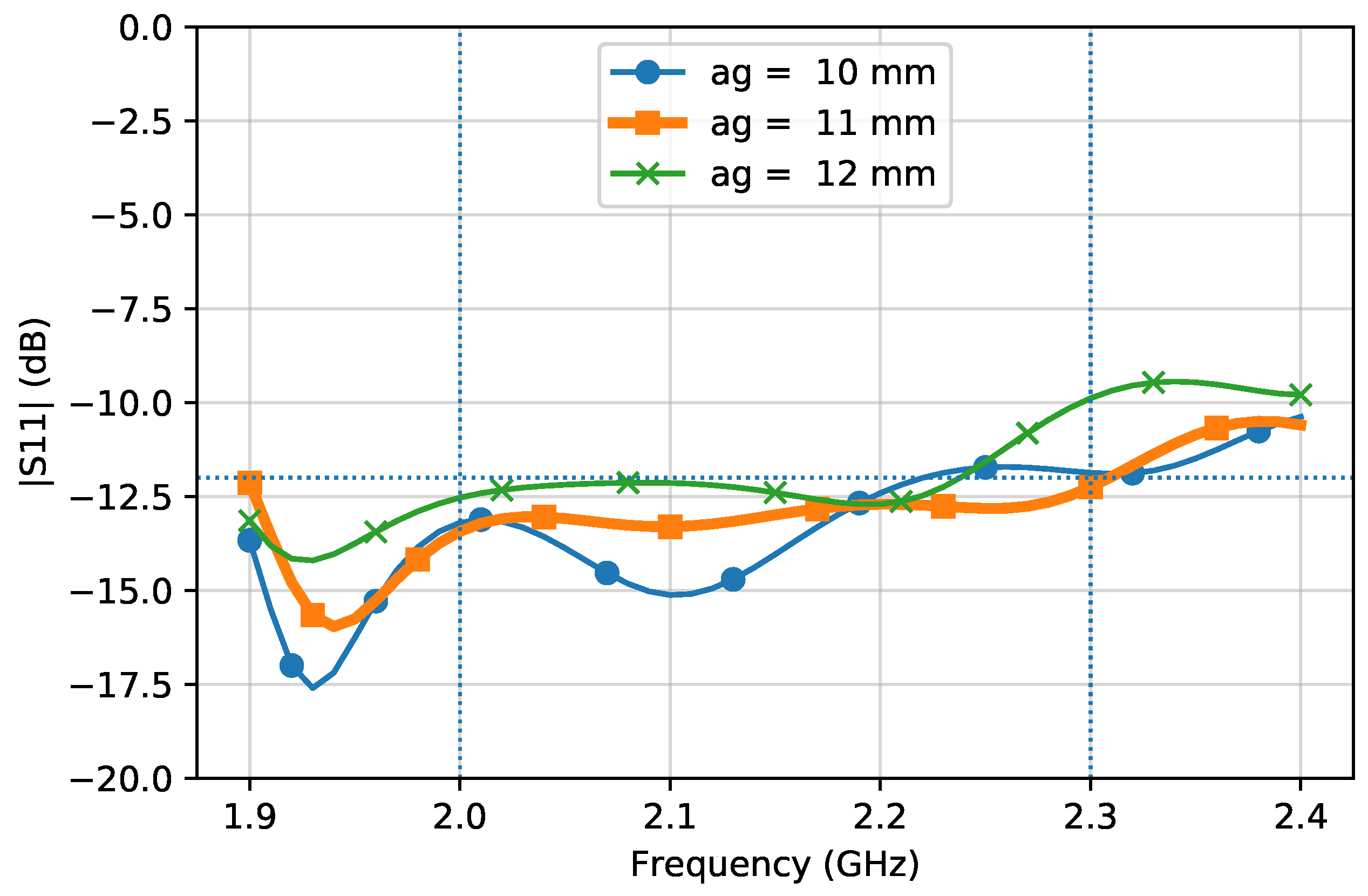
3.2. Air Gap
4. Radome Geometry
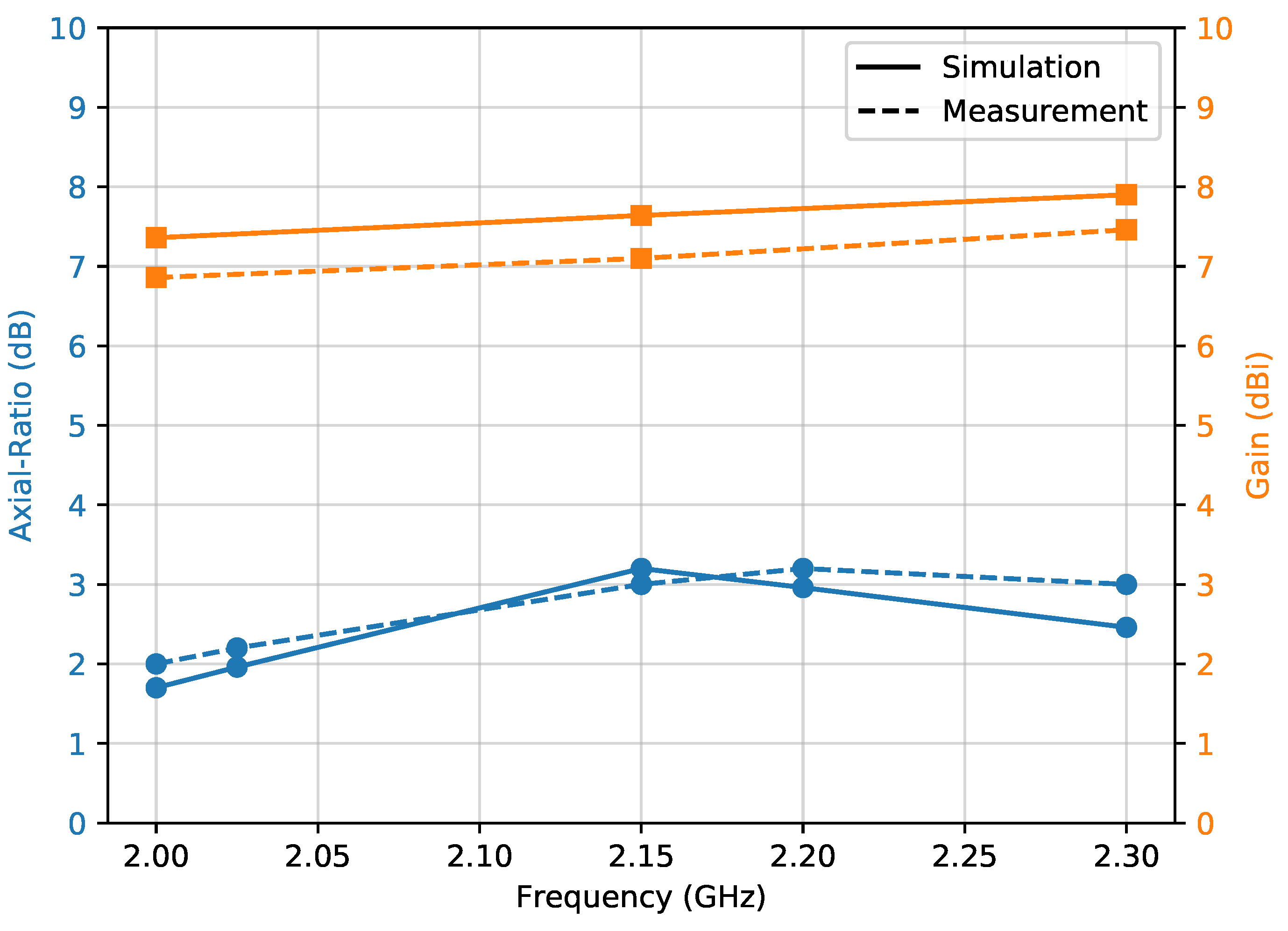
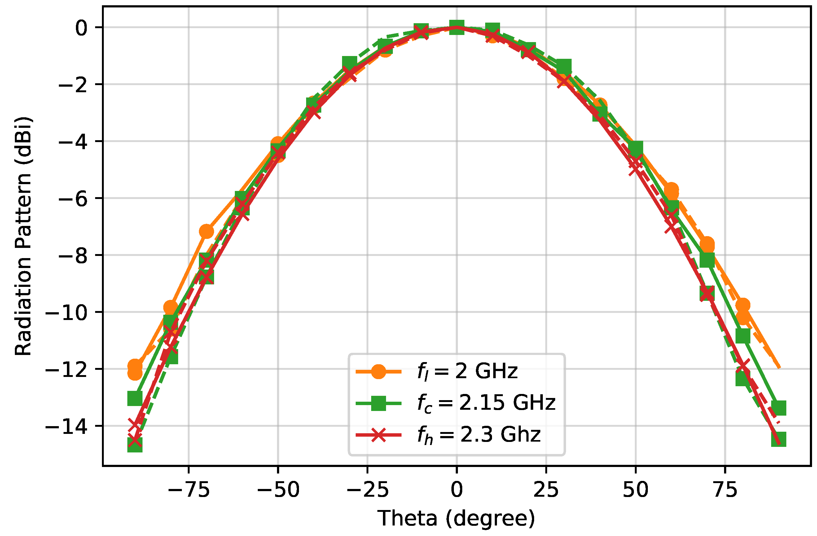
5. Results
6. Conclusions
Author Contributions
Funding
Acknowledgments
Conflicts of Interest
Abbreviations
| TT&C | Telemetry, Tracking and Command |
| CP | Circularly Polarized |
| AR | Axial Ratio |
| RHCP | Right Hand Circular Polarized |
| LHCP | Left Hand Circular Polarized |
References
- Tatomirescu, A.; Pedersen, G. Compact S Band Antenna for CubeSat. In Proceedings of the 2018 International Conference on Communications (COMM), Bucharest, Romania, 14–16 June 2018; pp. 231–234. [Google Scholar] [CrossRef]
- Kramer, H.J.; Cracknell, A.P. An overview of small satellites in remote sensing. Int. J. Remote. Sens. 2008, 29, 4285–4337. [Google Scholar] [CrossRef]
- Nascetti, A.; Pittella, E.; Teofilatto, P.; Pisa, S. High-Gain S-band Patch Antenna System for Earth-Observation CubeSat Satellites. IEEE Antennas Wirel. Propag. Lett. 2015, 14, 434–437. [Google Scholar] [CrossRef]
- ITU. Radio Regulations. Available online: http://handle.itu.int/11.1002/pub/8063030b-en (accessed on 15 May 2019).
- Ferrero, F.; Luxey, C.; Jacquemod, G.; Staraj, R. Dual-band circularly polarized microstrip antenna for satellite applications. IEEE Antennas Wirel. Propag. Lett. 2005, 4, 13–15. [Google Scholar] [CrossRef]
- Choi, E.; Lee, J.W.; Lee, T. Modified S-Band Satellite Antenna With Isoflux Pattern and Circularly Polarized Wide Beamwidth. IEEE Antennas Wirel. Propag. Lett. 2013, 12, 1319–1322. [Google Scholar] [CrossRef]
- Choi, E.; Lee, J.W.; Lee, T.; Lee, W. Circularly Polarized S-Band Satellite Antenna With Parasitic Elements and Its Arrays. IEEE Antennas Wirel. Propag. Lett. 2014, 13, 1689–1692. [Google Scholar] [CrossRef]
- Veljovic, M.J.; Skrivervik, A.K. Aperture-Coupled Low-Profile Wideband Patch Antennas for CubeSat. IEEE Trans. Antennas Propag. 2019, 67, 3439–3444. [Google Scholar] [CrossRef]
- Hu, W.; Wen, G.; Inserra, D.; Huang, Y.; Li, J.; Chen, Z.D. A Circularly Polarized Antenna Array with Gain Enhancement for Long-Range UHF RFID Systems. Electronics 2019, 8, 400. [Google Scholar] [CrossRef]
- Samsuzzaman, M.; Islam, M.T.; Faruque, M.R.I. Circularly polarized dual frequency patch antenna for TTC applications. In Proceedings of the 2013 Third World Congress on Information and Communication Technologies (WICT 2013), Hanoi, Vietnam, 15–18 December 2013; pp. 258–261. [Google Scholar] [CrossRef]
- Padilla, J.; Rosati, G.; Ivanov, A.; Bongard, F.; Vaccaro, S.; Mosig, J. Multi-functional miniaturized slot antenna system for small satellites. In Proceedings of the 5th European Conference on Antennas and Propagation (EUCAP), Rome, Italy, 11–15 April 2011; pp. 2170–2174. [Google Scholar]
- Leonardi, O.; Pavone, M.G.; Sorbello, G.; Morabito, A.F.; Isernia, T. Compact single-layer circularly polarized antenna for short-range communication systems. Microw. Opt. Technol. Lett. 2014, 56, 1843–1846. [Google Scholar] [CrossRef]
- Zaid, J.; Abdulhadi, A.; Kesavan, A.; Belaizi, Y.; Denidni, T. Multiport circular polarized RFID-tag antenna for UHF sensor applications. Sensors 2017, 17, 1576. [Google Scholar] [CrossRef] [PubMed]
- Sitompul, P.P.; Sumantyo, S.; Tetuko, J.; Kurniawan, F.; Nasucha, M. Axial Ratio and Gain Enhancement of a Circular-Ring Slot Antenna Using a Pair of Asymmetrical Rectangular Slots and a Parasitic Patch for a Radio Beacon on a Nanosatellite. Aerospace 2019, 6, 39. [Google Scholar] [CrossRef]
- Leonardi, O.; Pavone, M.; Cadili, T.; Sorbello, G.; Isernia, T. Monolithic patch antenna for dedicated short-range communications. Electron. Lett. 2013, 49, 85–86. [Google Scholar] [CrossRef]
- Di Carlo, C.; Di Donato, L.; Mauro, G.; La Rosa, R.; Livreri, P.; Sorbello, G. A circularly polarized wideband high gain patch antenna for wireless power transfer. Microw. Opt. Technol. Lett. 2018, 60, 620–625. [Google Scholar] [CrossRef]
- Kokotoff, D.M.; Aberle, J.T.; Waterhouse, R.B. Rigorous analysis of probe-fed printed annular ring antennas. IEEE Trans. Antennas Propag. 1999, 47, 384–388. [Google Scholar] [CrossRef]
- Someda, C.G. Electromagnetic Waves; CRC Press: Boca Raton, FL, USA, 2006. [Google Scholar]
- Mauro, G.S.; Torrisi, G.; Mariano, P.D.; Squadrito, C.; Emanuele, S.; Donato, L.D.; Sorbello, G. Wide Bandwidth Dual Port, Dual Sense Circular Polarization Antenna for Satellite Applications. In Proceedings of the ICEAA 2019 International Conference on Electromagnetics in Advanced Applications, IEEE-APS Topical Conference on Antennas and Propagation in Wireless Communications, Granada, Spain, 9–13 September 2019. [Google Scholar]


| R2out | R2in | R1out | R1in | S1 | S2 | fr | fx | fy | h2 | h1 | ag |
|---|---|---|---|---|---|---|---|---|---|---|---|
| 23.837 | 8.351 | 16.061 | 5.261 | 12.204 | 5.76 | 14.6 | 10.323 | 10.323 | 1.524 | 3.175 | 11.17 |
| ag = 9 (mm) | ag = 11 (mm) | ag = 13 (mm) | |||
|---|---|---|---|---|---|
| (GHz) | 1.008 | 1.209 | 1.396 | ||
| 96.96 | 92.38 | 86.02 | |||
| (GHz) | 1.506 | 1.221 | 0.963 | ||
| 72.78 | 75.99 | 78.46 | |||
| (GHz) | 1.351 | 1.141 | 0.968 | ||
| 58.56 | 71.94 | 89.97 | |||
| (GHz) | 1.126 | 1.259 | 1.563 | ||
| 73.49 | 97.87 | 119.39 |
© 2019 by the authors. Licensee MDPI, Basel, Switzerland. This article is an open access article distributed under the terms and conditions of the Creative Commons Attribution (CC BY) license (http://creativecommons.org/licenses/by/4.0/).
Share and Cite
Squadrito, P.; Livreri, P.; Di Donato, L.; Squadrito, C.; Sorbello, G. A Telemetry, Tracking, and Command Antennas System for Small-Satellite Applications. Electronics 2019, 8, 689. https://doi.org/10.3390/electronics8060689
Squadrito P, Livreri P, Di Donato L, Squadrito C, Sorbello G. A Telemetry, Tracking, and Command Antennas System for Small-Satellite Applications. Electronics. 2019; 8(6):689. https://doi.org/10.3390/electronics8060689
Chicago/Turabian StyleSquadrito, Paolo, Patrizia Livreri, Loreto Di Donato, Concetto Squadrito, and Gino Sorbello. 2019. "A Telemetry, Tracking, and Command Antennas System for Small-Satellite Applications" Electronics 8, no. 6: 689. https://doi.org/10.3390/electronics8060689
APA StyleSquadrito, P., Livreri, P., Di Donato, L., Squadrito, C., & Sorbello, G. (2019). A Telemetry, Tracking, and Command Antennas System for Small-Satellite Applications. Electronics, 8(6), 689. https://doi.org/10.3390/electronics8060689