Article

Fuzzy Optimized MFAC Based on ADRC in AUV Heading Control

School of Information Science and Engineering, Ocean University of China, Qingdao 266000, China
*
Author to whom correspondence should be addressed.
Electronics 2019, 8(6), 608; https://doi.org/10.3390/electronics8060608
Submission received: 23 April 2019 / Revised: 27 May 2019 / Accepted: 27 May 2019 / Published: 30 May 2019
(This article belongs to the Section Systems & Control Engineering)

Abstract

:
The control issue of Autonomous Underwater Vehicles (AUV) is very challenging since the precise mathematical model of AUV is hard to establish due to its strong coupling and time-varying features. Meanwhile, AUV movement is easily interfered with by ocean currents and waves, causing anti-interference performance of traditional Proportional-Integral-Derivative (PID) control to be unsatisfactory. Aiming to solve those problems, an algorithm of fuzzy optimized model-free adaptive control (MFAC) based on auto-disturbance rejection control (ADRC) was proposed and used in AUV heading control. The MFAC is used to overcome the difficulty with establishing a precise mathematical model, and the ADRC is introduced to handle the interference of currents and waves. In this paper, MFAC and ADRC are combined. First, the MFAC is performed based only on the I/O data of the controlled object, which is simple to implement with low calculation complexity and strong robustness. Then, a tracking differentiator (TD) is employed to track the input signal to overcome the antinomy of rapidity and hypertonicity in MFAC. After that, an extended-state observer (ESO) is added to control the variables of MFAC to estimate all the disturbances, which can greatly improve the anti-interference ability of the system. Due to the complexity and diversity of the marine environment, a fuzzy optimized MFAC based on ADRC is proposed to improve the adaptability of AUV to the marine environment. Simulations and experiments were carried out to verify the control effect of this algorithm in complex sea conditions.

1. Introduction

The autonomous underwater vehicle (AUV) is extensively used in port security monitoring, underwater search and rescue, naval application, and other fields. Motion control technology is one of the critical technologies to guarantee the underwater robot accomplishes particular tasks successfully [1]. In the past few decades, many control algorithms such as Proportional-Integral-Derivative (PID) control, sliding mode adaptive control, predictive adaptive control, backstepping control, feedback linearization adaptive control, and neural network adaptive control etc. have been researched in many aspects [2]. However, the state-of-the-art method still makes it difficult to ensure the stability and robustness of the AUV control system. Feedback linearization adaptive control, backstepping control, predictive adaptive control, and sliding mode adaptive control are all model-based adaptive control methods. When designing a control system with these methods, it is necessary to know the accurate mathematical model of the controlled system [3]. Although neural network adaptive control is not necessary to establish a precise mathematical model, the training of a neural network model also requires a large amount of system operation data, and many common problems of model-based control still exist [4]. Although PID control is not needed to establish a mathematical model, it is more suitable for linear systems, and not perfect for system control with strong nonlinear, time-varying, and periodic perturbations. It does not have the function of learning and adapting to the structural changes of the system, thus causing worse control performance, with slow response, frequent overshooting, and other shortcomings. MFAC is a control method based on a nonlinear system, which can realize nonlinear adaptive control with adaptive parameters and structure. Compared with the traditional PID control algorithm, MFAC has stronger robustness and anti-interference ability.
The MFAC has been explored and applied in military engineering, automobiles, electric power, and other industries, and that works well. However, there is little research about MFAC in terms of the AUV control system. This paper designs an AUV controller by MFAC. Its feasibility and effectiveness are verified by experiments and simulations. MFAC has been studied by experts and scholars in many other scenarios. In automobile systems, MFAC was used for the preview-deviation-yaw tracking problem and works well [5]. In addition, in electric power systems, a method combining MFAC algorithm and data-driven virtual reference feedback tuning control was introduced, which can effectively reduce the convergence error [6]. For nonlinear discrete-time systems, the control method of MFAC and its combination with other control methods was put forward, and the effective results have been obtained. Liu et al. designed a data-driven MFAC algorithm and got a perfect control effect [7], Xu et al. discussed a new model-free adaptive sliding mode control, which can facilitate the efficient by using the constrained tracking error [4], Dong et al. introduced a model-free adaptive predictive control algorithm, which has significantly smaller overshoot and shorter rising time [6]. Hui et al. proposed a new MFAC with an ESO in order to deal with the disturbance and uncertainty of a class of nonlinear systems, and the feasibility and effectiveness of the proposed method has been proved [8]. In the networked system, MFAC combined with predictive control was proposed for the problem of network-induced time delay and packet dropouts [9].
However, MFAC can only inhibit the unknown disturbance within a definite range. When the disturbance exceeds a certain range, MFAC cannot implement effective control [10]. To deal with this problem, ADRC is introduced to MFAC. ADRC provides a smooth input signal, and estimates and compensates internal and external disturbances for MFAC, which greatly improves the anti-interference ability of MFAC. The ADRC is widely used in the AUV control system and other fields. The ADRC consists of three constituent components, a tracking differentiator (TD), an extended-state observer (ESO), and a linear-state error feedback (LSEF). The function of TD is to provide smooth input signals for the controller, overcoming the contradiction between rapidity and hypertonicity. ESO is the key part of the ADRC, which can dynamically estimate and compensate for uncertain interference in real time, and greatly improve the anti-interference ability of the system. Many experts have studied ADRC from different aspects and perspectives. In an AUV control system, Chen et al. verified that the ADRC method is feasible and effective for the depth control through simulation [11]. Xu et al. introduced ADRC to guarantee robustness and stability during diving [12]. Aiming at solving the uncertainty of the sensor, an adaptive extended-state observer (AESO) was introduced and achieved good performance [13]. In other fields, ADRC also shows great control effect. ADRC and Embedded Model Control (EMC) were combined to estimate the disturbances and uncertainties affecting unmanned aerial vehicles (UAV) and eliminate them online [14]. For the powered parafoil, Luo et al. proposed an accurate flight-path-tracking control approach combining ADRC and wind feedforward compensation, which can achieve better tracking performance and robustness against the variable wind disturbance [15]. For flexible air-breathing hypersonic vehicles (FAHVs), a conditional disturbance negation (CDN)-based ADRC scheme was used for velocity and altitude tracking control in the presence of various uncertainties and disturbances [16]. The algorithm combined reinforcement learning with ADRC and was compared with classical ADRC by simulation based on the dynamic model of the OUC-III underwater glider [17].
Because of the complexity and diversity of the sea environment, fuzzy control is added to the control method of MFAC based on ADRC to improve the adaptability of AUV to the marine environment. Fuzzy control has been widely applied to the control of underwater vehicles and other fields. Zhong et al employed an augmented fuzzy observer and a compensation technique to eliminate the influence on the system performance stemming from the unknown output delays and achieve tracking control of AUV [18]. Zhang et al. proved that interval type-2 fuzzy logic controllers can improve and optimize tracking accuracy and eliminate stickslip [19], and an augmented fuzzy observer was proposed to attenuate the negative impact from the unknown output delays, which likely degrade the performance stability of the control systems [18]. Patre et al. adopted a fuzzy logic control (FLC) tool to generate the control signal in order to reduce chattering in control inputs, which commonly occur in conventional terminal sliding mode controller (TSMC), and an estimated uncertainty term to compensate for the unmodeled dynamics, external disturbances, and time-varying parameters [20]. For the photovoltaic (PV) system application, a novel beta-parameter three-input one-output fuzzy-logic-based maximum-power point-tracking (MPPT) algorithm was presented and the advantages of the proposed algorithm are verified [21]. Thanana Nuchkrua et al. adopted a fuzzy self-tuning PID control of hydrogen-driven Pneumatic Artificial Muscle (PAM) actuator and the results of the implementation show the viability of the proposed method [22]. George et al. designed and experimented with a fuzzy proportional-integral-derivative (PID) controller for a flexible-joint robot arm with uncertainties from time-varying loads [23]. A fuzzy particle swarm optimization of PID control (PSO-FPIDC) used for a conventional power system stabilizer (CPSS) was presented to improve the dynamic stability performance of the generating unit during low-frequency oscillations [24]. Petrov et al. described a fuzzy PID controller based on Sugeono’s fuzzy technique with fuzzy neural implementation; simulations demonstrate satisfactory results of the performance and implementation applied to a nonlinear plan composed of two cascaded water tanks with level control [25].
This paper combines the advantages of ADRC with MFAC and fuzzy control, and designs an advanced intelligent control algorithm—fuzzy optimized MFAC based on ADRC algorithm. The major contributions of this work are highlighted as follows:
• Model-Free Adaptive Control
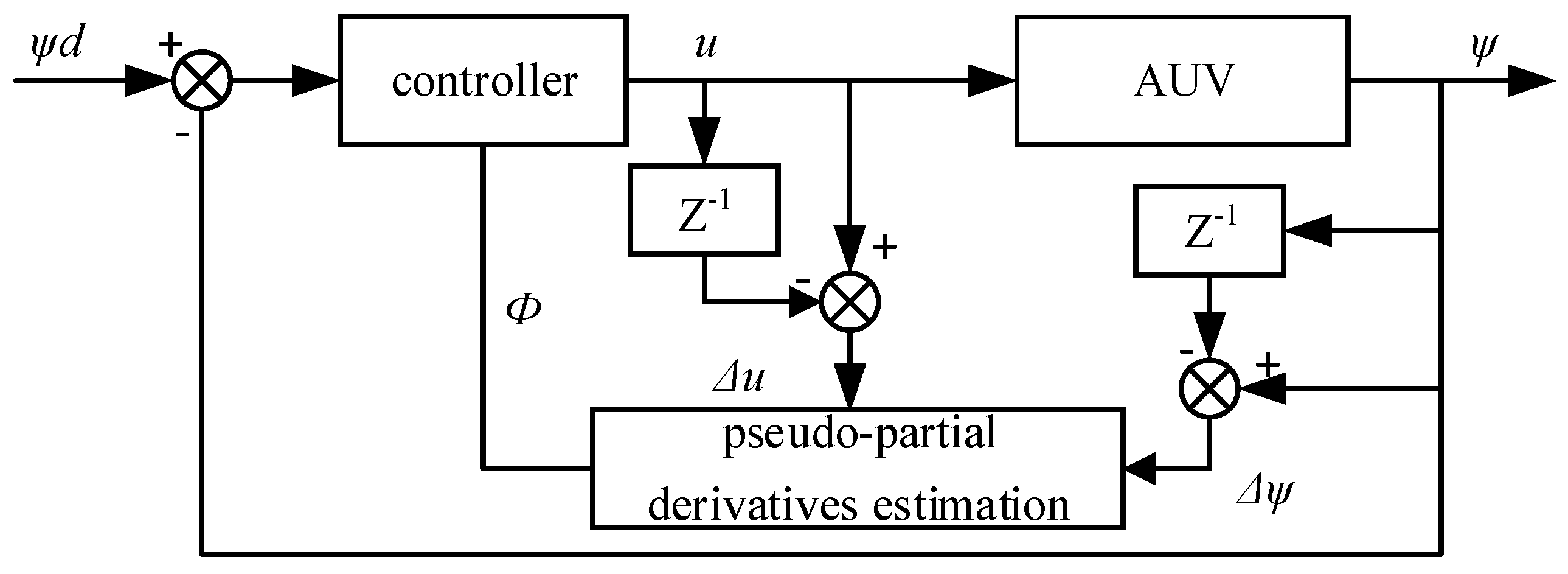
At each key point, the equivalent dynamic linearized data model of the nonlinear system is established, and the pseudo-partial derivatives (PPD) of the system is estimated online by using the I/O data of the controlled system. Then, a controller weighted one step forward is designed to realize the MFAC driven by the data of the nonlinear system.
• Model-Free Adaptive Control based on Auto-Disturbance Rejection Control
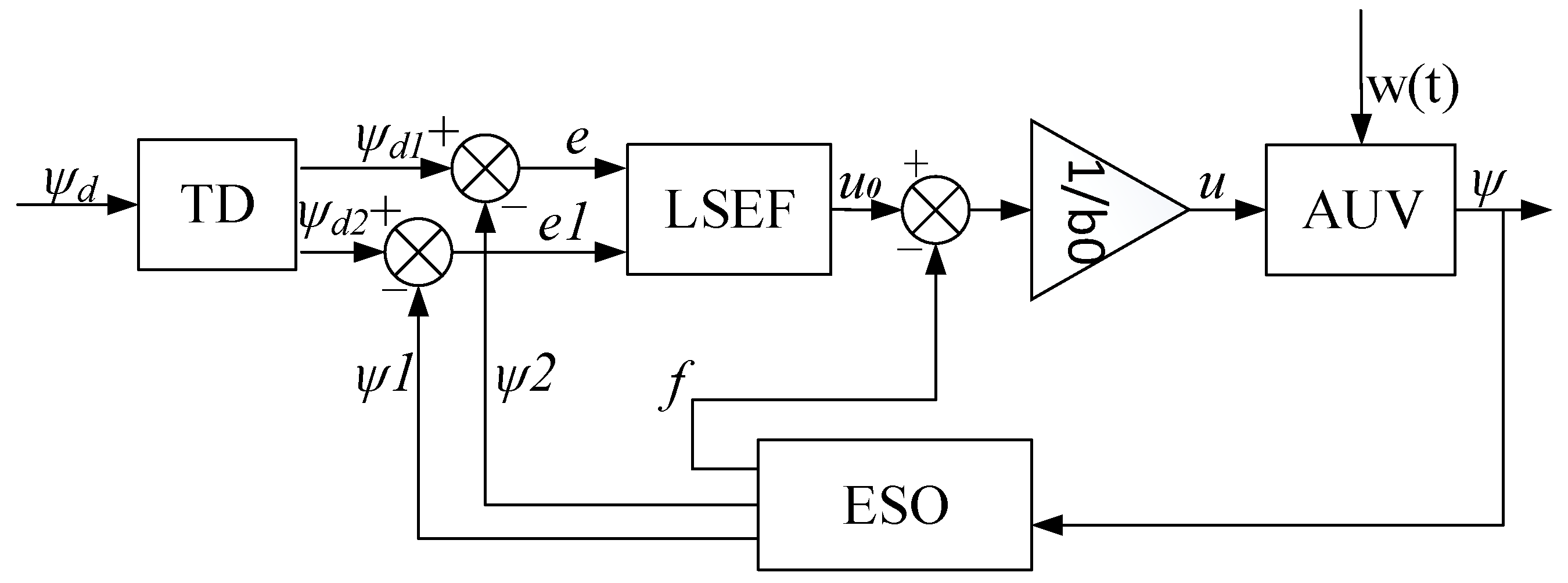
The ADRC consists of three parts: TD, ESO, and LSEF. The TD tracks input signal and its differential. The key part of the linear ADRC is the ESO, which estimates all uncertain disturbances of the system in real time. With the error combined by linear function, the LSEF finally transmits a control variable to the controlled system.
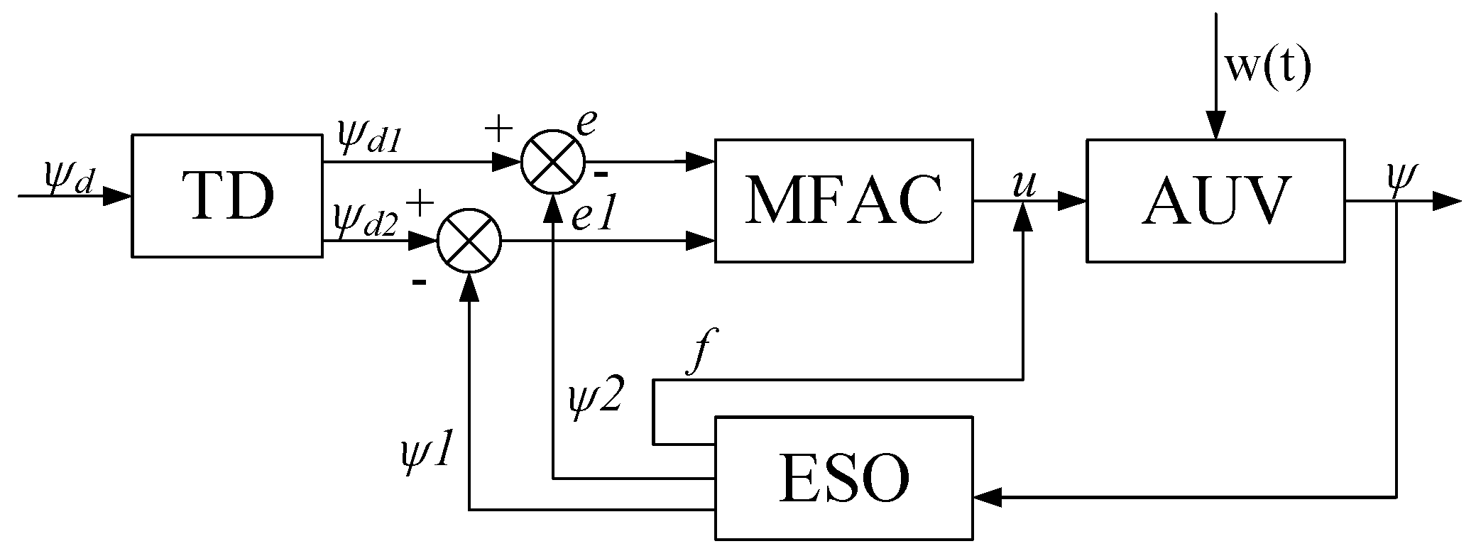
The input signal tracked by TD and the disturbance estimated by the ESO are both added to MFAC in this paper. The signal tracked by TD is applied to replace the input signal of MFAC, and the disturbance estimated by the ESO is added to the output control variable of MFAC.
• Fuzzy Optimized Model-Free Adaptive Control based on Auto-Disturbance Rejection Control
Through the analysis of the key parameters of MFAC based on ADRC, it is found that the key parameter ρ has a great influence on the performance of the control system. Therefore, a parameter self-tuning method is proposed, i.e., to optimize the self-tuning key parameter ρ through fuzzy control.
The rest of the paper is organized as follows. After an AUV model is introduced in the next section, the controller designs are explained in Section 3. In Section 4, a lot of simulations and experiments are carried out, and the results are analyzed and discussed in terms of accuracy, speed, and anti-interference performance. The last section summarizes the important conclusions of this work.

2. AUV Model

2.1. Coordinate System and Dynamic Model of AUV

Because an AUV has six degrees of freedom (DOF), it has good handleability. Figure 1 shows the two coordinate systems. Based on the two coordinate systems, the nonlinear motion equations of the six DOFs for an AUV are defined.
The airborne coordinate system ( o x y z ) has six velocity elements of motion (surge, sway, heave, roll, pitch, and yaw). The velocity vector in the vehicle coordinate system is v = [ u , v , ω , p , q , r ] T , and the global coordinate system ( E ξ η ζ ) is a fixed coordinate system. Translation and rotation in the global reference frame are proposed through τ = [ x , y , z , ϕ , θ , ψ ] T , which contains fixed earth positions and Euler angle [2].
X v i s = m [ v r + w q ] m z G p r + 1 / 2 ρ L 4 [ X q q q 2 + X r r r 2 + X r p r p ] + 1 / 2 ρ L 3 [ X v r + X w q ] + 1 / 2 ρ L 2 [ X u u u 2 + X v v v 2 + X w w w 2 ]
Y v i s = m [ u r w p ] m z G q r + 1 / 2 ρ L 4 [ Y p p p p + Y p q p q + Y q r q r ] + 1 / 2 ρ L 3 [ Y v q v q + Y w p w p + Y w r w r ] + 1 / 2 ρ L 3 [ Y r u r + Y p u p + Y v r v v ( v 2 + w 2 ) 1 / 2 r ] + 1 / 2 ρ L 2 [ Y 0 u 2 + Y v v ( v 2 + w 2 ) 1 / 2 ] + 1 / 2 ρ L 2 Y v w v w
Z v i s = m [ u q v p ] + m z G ( p 2 + q 2 ) + 1 / 2 ρ L 4 [ Z r r r 2 + Z p p p 2 + Z r p r p ] + 1 / 2 ρ L 3 [ Z v r v r + Z v p v p ] + 1 / 2 ρ L 3 [ Z q u q + Z w q w w ( v 2 + w 2 ) 1 / 2 q ] + 1 / 2 ρ L 2 [ Z 0 u 2 + Z w u w + Z w w w ( v 2 + w 2 ) 1 / 2 ] + 1 / 2 ρ L 2 [ Z w u w + Z w w w ( v 2 + w 2 ) 1 / 2 ] + 1 / 2 ρ L 2 Z v v v 2
K v i s = ( I z I y ) r q m z g ( w p + u r ) + 1 / 2 ρ L 5 [ K q r q r + K p q p q + K p p p p ] + 1 / 2 ρ L 4 [ K p u p + K r u r ] + 1 / 2 ρ L 4 [ K v q v q + K w p w p + K w r w r ] | 1 / 2 ρ L 3 [ K 0 u 2 + K v u v + K v v v ( v 2 + w 2 ) 1 / 2 ] + 1 / 2 ρ L 3 K v w v w g h c o s θ s i n ψ
M v i s = ( I x I z ) p r m z G ( v r w q ) + 1 / 2 ρ L 5 [ M p p p 2 + M r r r 2 + M r p r p + M q q q q ] + 1 / 2 ρ L 4 [ M v r v r + M v p v p ] + 1 / 2 ρ L 4 [ M q u q + M w q ( v 2 + w 2 ) 1 / 2 q ] + 1 / 2 ρ L 3 [ M 0 u 2 + M w u w + M w w w ( v 2 + w 2 ) 1 / 2 ] + 1 / 2 ρ L 3 [ M w u w + M w w ( v 2 + w 2 ) 1 / 2 ] + 1 / 2 ρ L 3 M v v v 2
N v i s = ( I y I z ) p q + 1 / 2 ρ L 5 [ N p q p q + N q r q r + N r r r r ] + 1 / 2 ρ L 4 [ N w r w r + N w p w p + N v q v q ] + 1 / 2 ρ L 4 [ N p u p + N r u r + N v r ( v 2 + w 2 ) 1 / 2 r ] + 1 / 2 ρ L 4 [ N 0 u 2 + N v u v + N v v v ( v 2 + w 2 ) 1 / 2 ] + 1 / 2 ρ L 3 N v w v w
Where: m: AUV mass; z G : barycentric coordinate of AUV; I x , I y , I z : moments of inertia about x, y and z axes; X u ˙ , Y v ˙ , Y r ˙ , Z w ˙ , Z q ˙ , Z p ˙ , K p ˙ , K r ˙ , M q ˙ , N v ˙ , N r ˙ etc.: hydrodynamic coefficients;
The AUV is easily influenced by its surroundings when operating in the ocean. The seawater is approximately uniformly mixed in the range of 0–100 m below sea level [26]. The temperature, salinity, and density have a little influence on the motion performance of AUV and can be neglected, thus sea current interference is the only interference we need to consider. Suppose that the current is parallel to the water level of the fixed coordinate system, and the current is constant [27]. In the current circumstances, the relative velocity as shown in (7)–(9).
u r = u U c c o s θ c o s ( α ψ )
v r = v U c s i n θ
ω r = ω U c s i n θ c o s ( α ψ )
U c is the revolutional flow of the current speed, and the α is the angle of the current. After the time derivative, Equations (7)–(9) can be written as the component of Equations (10)–(12).
u r ˙ = u ˙ + U c q s i n θ c o s ( α ψ ) U c r c o s θ s i n ( α ψ )
v r ˙ = v ˙ U c s i n ( α ψ )
ω r ˙ = ω ˙ U c q c o s θ c o s ( α ψ ) U c r s i n θ s i n ( α ψ )
Hence, the parameters v and v ˙ are changed as follows.
v = [ u + u r , v + v r , ω + ω r , p , q , r ]
v ˙ = [ u ˙ + u ˙ r , v ˙ + v ˙ r , ω ˙ + ω ˙ r , p ˙ , q ˙ , r ˙ ]

2.2. Horizontal Equation of Motion

The equation of motion can be divided into two equations of motion for purpose of analyzing the maneuvering capability—the horizontal equation and the vertical equation, assuming that the center of gravity is in the origin of the AUV and the heave, roll, and pitch can be ignored. Then the horizontal equation can be expressed as (15).
m ( u ˙ v r ) = X m ( v ˙ + u r ) = Y I z r ˙ = N
Assuming that the that cruise speed u is a constant and u ˙ is zero, the X equation can be exenterated. After that, the linearized equation can be shown as (16).
( m Y v ˙ ) ( v ˙ ) Y v v + Y r ˙ r ˙ + ( m V Y r ) r = Y δ δ ( I z N r ˙ ) r ˙ N r r + N v ˙ v ˙ N v v = N δ δ
Due to starboard–port symmetry of AUV, Y r ˙ and N v ˙ are zero. Given T y = Y δ , N y = N δ [2]. The equation simplifies to (17).
( m Y v ˙ ) v ˙ Y v v + ( m V Y r ) r = T y ( I z N r ˙ ) r ˙ N r r N v v = N y
Ignoring the element corresponding to roll finally yields [2]:
B 2 v ¨ + B 1 v ˙ + B 0 v = ( I z N r ˙ ) T ˙ y N r T y ( m V Y r ) N y
where
B 2 = ( I z N r ˙ ) ( m Y v ˙ )
B 1 = Y v ( I z N r ˙ N r ( m Y v ˙ )
B 0 = ( N v ( m V Y r ) + Y v N r
Therefore, through Laplace transform, the following equation is:
G 1 ( s ) = ( I z N r ˙ ) s N r B 2 s 2 + B 1 s + B 0

3. Controller Design

3.1. AUV Heading Control System

The heading control system must be carried out to ensure the accuracy and stability of the heading during sailing. The desired heading is controlled by computing and changing the vertical rudder angle. The actual heading was measured by attitude sensor. This paper uses fuzzy optimized MFAC based on ADRC to the compute the vertical rudder. The heading control system is shown in Figure 2.
Where ψ d is the desired heading, ψ the actual heading, and e the heading error between desired heading and actual heading.

3.2. Model-Free Adaptive Control

The heading control system of MFAC is shown in Figure 3.
For discrete-time nonlinear systems, MFAC uses a new dynamic linearization method and a new concept called PPD. First, an equivalent linearized dynamic data model is established for dynamic working points in each closed-loop system. In addition, based on the analysis of the control system theory of the equivalent controller, a virtual data model is established. Then, we realize the adaptive control of the nonlinear system. The PPD parameter can only be estimated by using the I/O measurement data of the controlled object [28]. There are three specific forms of dynamic linearization methods, including compact-format dynamic linearization (CFDL), partial format dynamic linearization (PFDL) and full-format dynamic linearization (FFDL). Dynamic linearization based on CFDL is adopted in this paper.
The MFAC method has the following advantages, which make it more suitable for the control of the actual system. First, MFAC only relies on the real-time measured data of the controlled system, and does not rely on any mathematical model information of the controlled system. It is a data-driven control method. This means that a universal controller can be independently designed for a class of practical industrial processes. Second, the MFAC method does not need any external test signal or training process, which is necessary for the nonlinear control method based on neural network [29]. Therefore, MFAC is a low-cost controller. Thirdly, the MFAC method is easy to implement with high robustness. Fourth, under some actual assumptions, the CFDL-based MFAC scheme can guarantee the monotone convergence and the stability of bounded input and bounded output of the tracking error of the closed-loop system, which is an important characteristic that is different from other data-driven control methods [28].
The single-input single-output (SISO) discrete-time nonlinear system is expressed as:
y ( k + 1 ) = f ( y ( k ) , , y ( k n y ) , u ( k ) , , u ( k n u ) )
where y ( k ) R and u ( k ) R represent the output and input signal of the nonlinear system at time k, n y and n u are two unknown positive integers, and f ( ) is the unknown nonlinear function.
Hypothesis 1 (H1).
Assume that the input and output signals are considerable and controllable, i.e., the input signal and the expected output signal of a system are bounded, so that the output of the system is equal to expected output under the secondary control signal [30].
Hypothesis 2 (H2).
The partial derivative of the current control input signal u ( k ) of the system is continuous for k [3].
Hypothesis 3 (H3).
The system is generalized Lipschitz, which is satisfied for any k and Δ u ( k ) 0
Δ y ( k + 1 ) b Δ u ( k )
where Δ y ( k + 1 ) = y ( k + 1 ) y ( k ) , Δ u ( k ) = u ( k ) u ( k 1 ) and b is a normal number.
If the system satisfies all above hypothesis, and conforms to all of them for any k time and Δ u ( k ) 0 , then:
Δ y ( k + 1 ) b Δ u ( k )
There must be a time-varying parameter φ ( k ) , which enables the system to be transformed into the following CFDL data model:
Δ y ( k + 1 ) = φ ( k ) Δ u ( k )
The dynamic linearization model based on the compact-format linearization method is proposed as follows:
y ( k + 1 ) = y ( k ) + φ ( k ) Δ u ( k )
φ ( k ) is obviously a time-varying parameter, and related to the input and output signal of the system up to the sampling time k. φ ( k ) can be considered to be a differential signal in some sense, and bounded at any time k. In fact, if the sampling time k and Δ u ( k ) are not very large, φ ( k ) is a slow time-varying signal.
For discrete-time systems, by minimizing the step-forward prediction error criterion function of control algorithm, excessive control input may be generated, and the control system itself may be destroyed, and by minimizing the weighted step-forward prediction error criterion function of control algorithm, a steady-state tracking error may accidentally be produced [9], so this paper introduces the control input cost function as:
J ( u ( k ) ) = y * ( k + 1 ) y ( k + 1 ) 2 + λ u ( k ) u ( k 1 ) 2
where λ is the weight factor, y * ( k + 1 ) the desired output signal.
Take the derivative of it and set it equal to zero, then:
u ( k ) = u ( k 1 ) + ρ φ ( k ) λ + φ ( k ) 2 ) ( y * ( k + 1 ) y ( k ) )
where: ρ is the step-length sequence.
Because the PPD of the system is unknown, we give the expression of the control algorithm with the online estimation of φ ( k ) :
u ( k ) = u ( k 1 ) + ρ φ ^ ( k ) λ + φ ^ ( k ) 2 ( y * ( k + 1 ) y ( k ) )
Since PPD is a time-varying parameter, its exact true value is difficult to obtain. Therefore, it is necessary to design an estimation algorithm that uses the input and output data of the controlled system to estimate PPD. The estimated criterion function of the pseudo-partial derivative is:
J ( φ ( k ) ) = y ( k ) y ( k 1 ) φ ( k ) Δ u ( k 1 ) 2 + μ φ ( k ) φ ( k 1 ) 2
The estimation algorithm of the pseudo-partial derivatives can be obtained according to the optimal conditions:
φ ^ ( k ) = φ ^ ( k 1 ) + η Δ u ( k 1 ) μ + Δ u ( k 1 ) 2 ( Δ y ( k ) φ ^ ( k 1 ) Δ u ( k 1 ) )
where η is the step-length sequence, μ the weight factor.
The final control algorithm is as follows:
φ ^ ( k ) = φ ^ ( k 1 ) + η Δ u ( k 1 ) μ + Δ u ( k 1 ) 2 ( Δ y ( k ) φ ^ ( k 1 ) Δ u ( k 1 ) )
φ ^ ( k ) = φ ^ ( 1 ) i f φ ^ ( k ) ϵ o r Δ u ( k 1 ) ϵ o r s i g n ( φ ^ ( k ) ) s i g n ( φ ^ ( k ) )
u ( k ) = u ( k 1 ) + ρ φ ^ ( k ) λ + φ ^ ( k ) 2 ( y * ( k + 1 ) y ( k ) )
where λ > 0 , μ > 0 , ρ ( 0 , 1 ] , η ( 0 , 1 ] , ϵ is a sufficiently small positive number, φ ^ ( 1 ) is the initial value of φ ^ ( k ) .

3.3. Model-Free Adaptive Control Based on Auto-Disturbance Rejection Control

To improve the anti-interference ability of the system, ADRC was introduced to MFAC. The heading control system of ADRC is shown in Figure 4.

3.3.1. Auto-Disturbance Rejection Control

The core theory of ADRC is based on simple integral series standard, which regards the standard parts (including the system uncertainties and disturbances) as different from the dynamic system as total disturbance (including the inner disturbances and outside disturbances) [15]. The total disturbances are estimated and eliminated by means of ESO in real time, thus simplify the disturbances, uncertainties, and nonlinear controlled object to the standard series of integral, making the design of the control system simple and intuitive.

Tracking Differentiator

The function of TD is as follows. The input signal can be divided into two outputs through TD. Based on the function of maximum velocity synthesis, ADRC establishes the maximum velocity feedback system and constructs the TD, which can realize the fast tracking of the input signal and the synchronous differential output, and can effectively reduce the noise amplification effect [31]. Thus, we provide a smooth input signal, reduce overshoot, promote system stability, and reduce the steady-state error.
The discrete algorithm of TD is given as follows:
f h = f h a n ( x 1 ( k ) v ( k ) , x 2 ( k ) , r , h )
x 1 ( k + 1 ) = x 1 ( k ) + h x 2 ( k )
x 2 ( k + 1 ) = x 2 ( k ) + h f h
where
d = r h
d 0 = h d
y = x 1 + h x 2
a = x 2 + a 0 d 2 s i g n ( y ) , y > d 0 . x 2 + y h , y d 0 ,
f h a n = r s i g n ( a ) , a > d . r a d , a d ,
where v ( k ) is the input signal of TD, and x 1 ( k ) , x 2 ( k ) are output signals of TD. h is for the integral step; r the parameter deciding to the track pace; f h a n the function of maximum velocity.

Extended-State Observer

ESO is the key part of the ADRC, which is used to solve the core problem of disturbance observation. In the auto-disturbance rejection technique, using the idea of ESO will affect the output of the object into a new state variable, which can attribute all inner and external disturbances to comprehensive disturbance, and estimate this disturbance [32]. Then, it makes a compensation according to the comprehensive disturbance. The ESO does not rely on generating a perturbation model, nor does it require direct measurements to observe the perturbation to obtain an estimate. It is a dynamic process, and estimates disturbance only by the input and output information of the control system. A three-order ESO is proposed as:
y ^ 1 ˙ = y ^ 2 l 1 ( y ^ 1 y ) y ^ 2 ˙ = f ^ l 2 ( y ^ 1 y ) + b 0 δ f ^ ˙ = l 3 ( y ^ 1 y ) ,
where y ^ 1 tracks y, y ^ 2 tracks the differential of y, y ^ 1 ˙ is the differential of y ^ 1 , y ^ 2 ˙ is the differential of y ^ 2 , f denotes the inner and external disturbance, f ^ the estimation of comprehensive disturbance of the system, f ^ ˙ the differential of f ^ , b 0 the compensation coefficient, l 1 , l 2 , l 3 the ESO output error weight factor.
For the linear-state error feedback with the error combined by linear function, a control variable is transmitted to the controlled system [16].The linear feedback error law is given as:
u 0 = k p e ^ + k d e ^ ˙
where e ^ = y y ^ 1 , e ^ ˙ = y ˙ y ^ 2
The final control law is:
u = u 0 f ^ b 0

3.3.2. Model-Free Adaptive Control Based on Auto-Disturbance Rejection Control

The MFAC based on ADRC is applied to the heading control of AUV. The input signal tracked by TD is added to the input of the MFAC. In addition, the disturbance estimated by the ESO is added to the control variable of MFAC. The block diagram of MFAC based on ADRC is shown in Figure 5:
The nonlinear system of the general system with interference is expressed as:
y ( k + 1 ) = f ( y ( k ) , , y ( k n y ) , u ( k ) , , u ( k n u ) ) + f ( k )
where f ( k ) is the system disturbance.
The dynamic linear equation of the system is:
Δ y ( k + 1 ) φ ( k ) Δ u ( k ) + Δ f ( k )
Then the dynamic linearization model based on compact format is as follows:
y ( k + 1 ) = y ( k ) + φ ( k ) ρ φ ^ ( k ) λ + φ ^ ( k ) 2 ( y * ( k + 1 ) y ( k ) ) + Δ f ( k )
where Δ f ( k ) is the error of disturbance signal.
The estimated linear interference is added to the control variable of this controller, and the control law is as follows:
u ( k ) = u ( k 1 ) ρ φ ^ ( k ) λ + φ ^ ( k ) 2 ( y * ( k + 1 ) y ( k ) Δ f ( k ) )
The output signal tracked by TD is added to the control variable of this controller, and the control law is as follows:
u ( k ) = u ( k 1 ) ρ φ ^ ( k ) λ + φ ^ ( k ) 2 ( y * ( k + 1 ) ˙ y ( k ) Δ f ( k ) ^ )
where y * ( k + 1 ) ˙ is the output signal tracked by TD, Δ f ( k ) ^ the estimated value of Δ f ( k ) . If the estimated value of the designed perturbation estimator can approximate the perturbation signal, the algorithm is effective for suppressing perturbation.
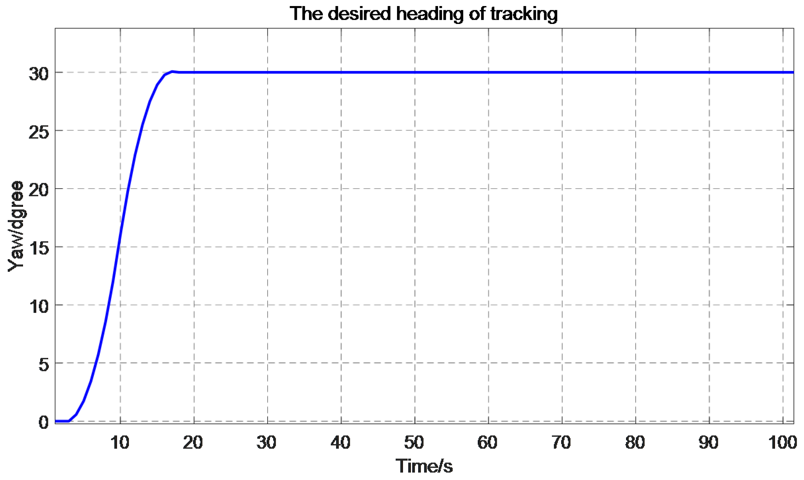
The input signal tracked by TD is shown in Figure 6, where the input signal is the desired heading. The desired heading is 30 degrees. The rising time is about 17 s.
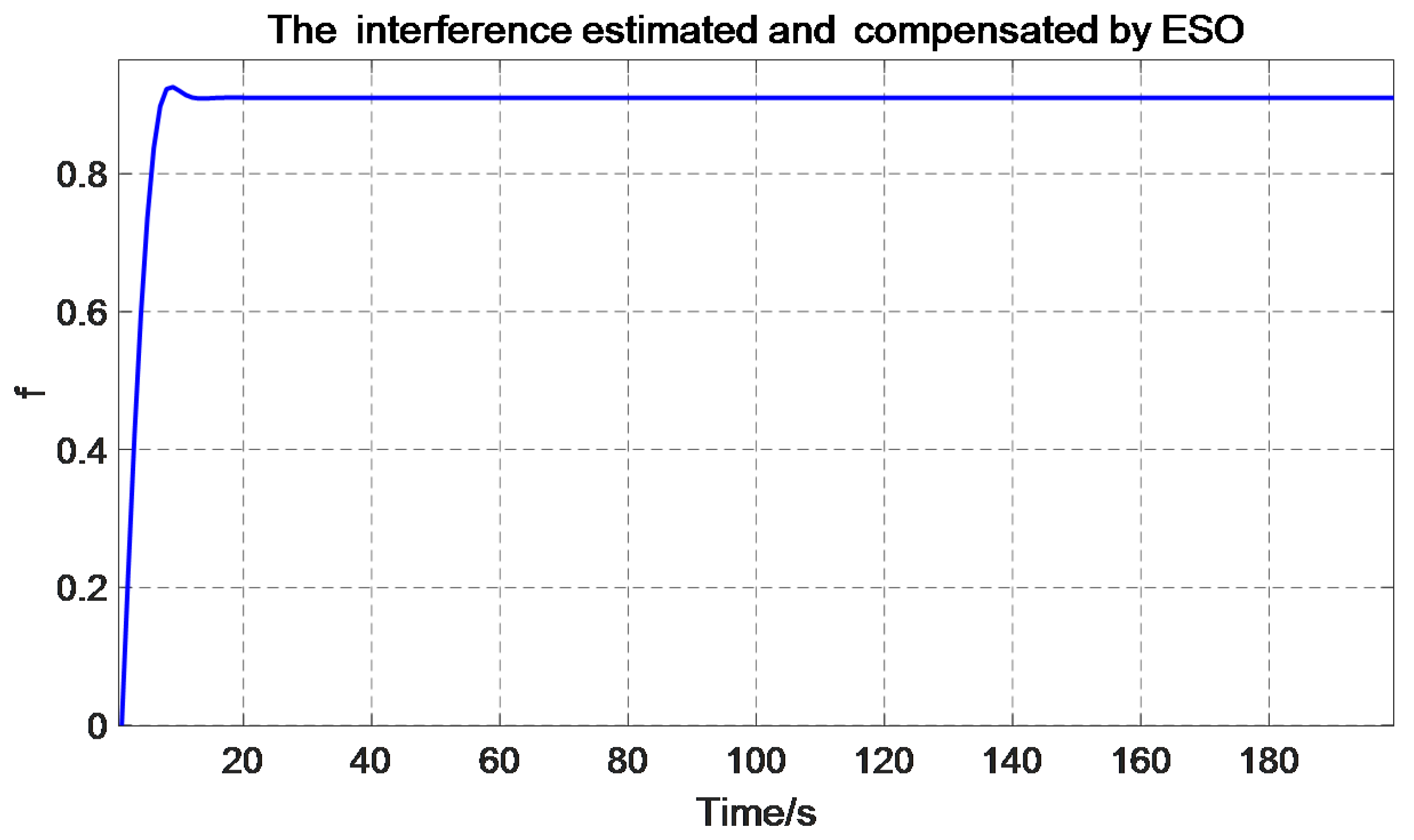
The interference estimated and compensated by ESO is shown in Figure 7, the velocity of AUV is 1.5 m/s, current velocity Uc is 0.5 m/s, and angle of current α is 45 degrees.
The TD can overcome the contradiction between rapidity and hypertonicity in MFAC by using the transition process of the reference input. The ESO makes a real-time dynamic estimation and compensation for the uncertain disturbances, which can greatly improve the anti-interference ability of the system. To tune coefficients, fuzzy control is added to the MFAC based on ADRC.

3.4. Fuzzy Optimized Model-Free Adaptive Control Based on Auto-Disturbance Rejection Control

Figure 8 shows the fundamental configuration of fuzzy control, which usually consists of three stages: fuzzification, interference with rule base, and defuzzification [33]. The main role of the fuzzification is to transform the digital input variables into equivalent language variables as input fuzzy sets [33]. After that, the fuzzy sets are dispatched to the interference for purpose of obtaining output fuzzy sets on basis of the fuzzy rule base table. At last, the output of digital variables can be obtained according to the output fuzzy sets.
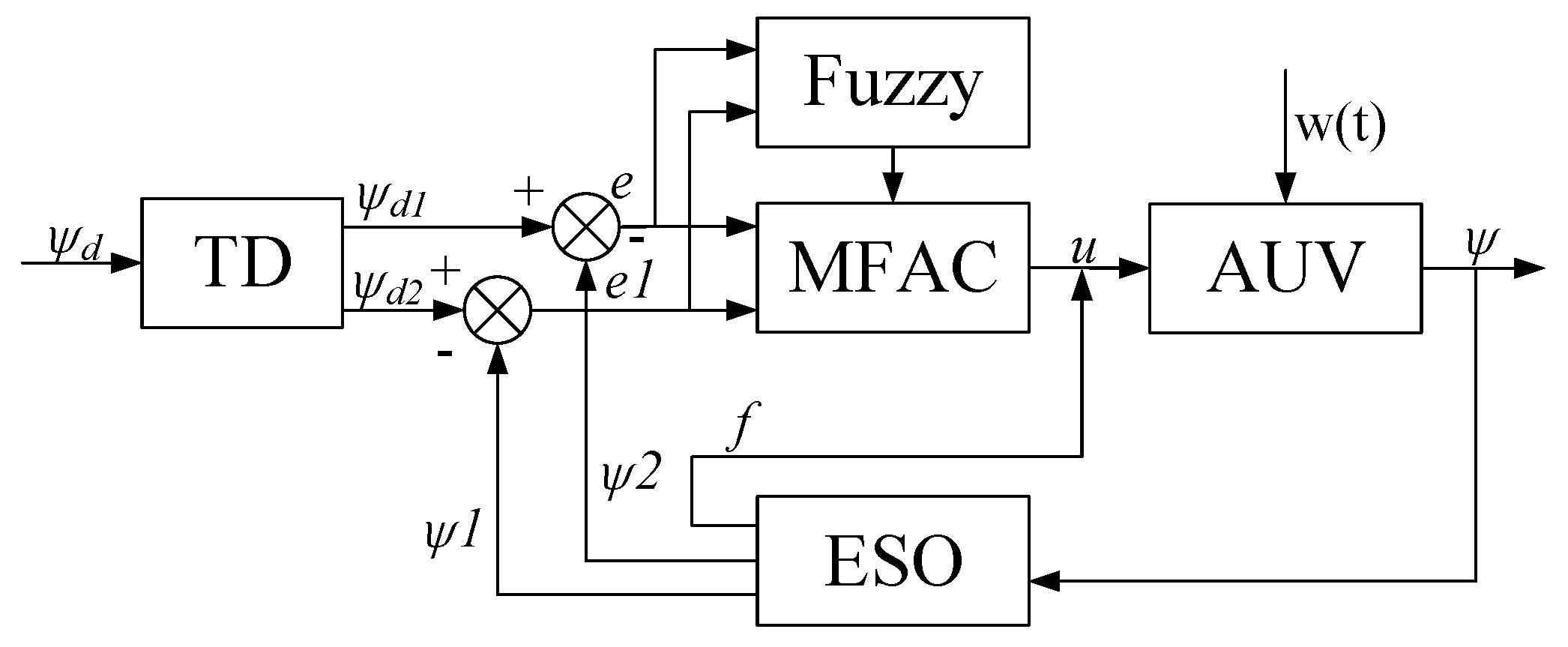
The structure of the control system with the proposed fuzzy optimized MFAC based on ADRC is shown in Figure 9.
The traditional fuzzy control usually works with input signal of the system error e and the change rate of error e c . System error is defined as the error between the expected output signal r ( k ) and the reference signal y ( k ) of the system at any time k, therefore e ( k ) = r ( k ) y ( k ) . Hence the change rate of error e c at that moment is: e c ( k ) = e ( k ) e ( k 1 ) .
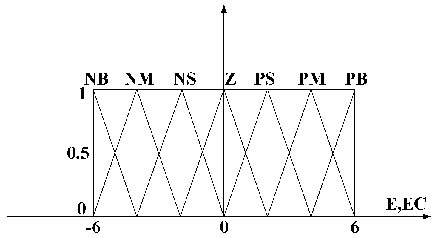
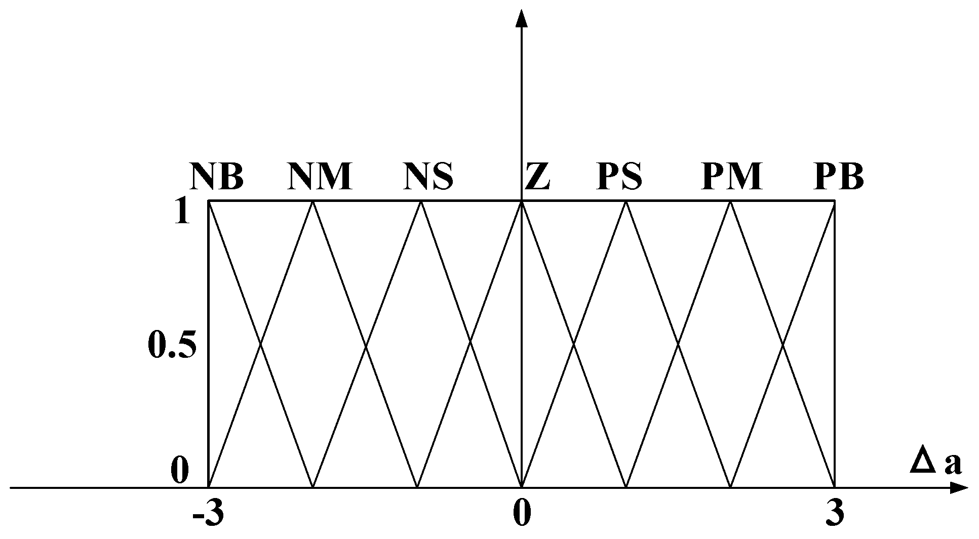
The error and the change rate of error is fuzzified by seven triangles into fuzzy sets represented by seven language variables. Based on design experience, all language variables range from −6 to +6. The language variables of fuzzy sets are defined as follows: NB—negative big, NM—negative medium, NS—negative small, Z—zero, PS—positive small, PM—positive medium, PB—positive big. The membership functions are shown in Figure 10 and Figure 11.
Fuzzy rules are the key factor of fuzzy control. The target of the task is to optimize real-time parameters of MFAC based on ADRC. Fuzzy optimized MFAC based on ADRC has 49 rules determined by the input variables (shown in Table 1). Fuzzy rules are derived from design experience and adjusted in accordance with controller performance. Fuzzy inference formed by the IF–THEN rules is used to construct a nonlinear mapping from fuzzy inputs to outputs [34].
If e is A and e c is B, then a is C.
It is known that the MFAC based on ADRC algorithm can be described with the discrete equations as follows:
u ( k ) = u ( k 1 ) ρ φ ^ ( k ) λ + φ ^ ( k ) 2 ( y * ( k + 1 ) ˙ y ( k ) Δ f ( k ) )
Through the analysis of key parameters of MFAC based on ADRC, it is found that the key parameter ρ has a great impact by the sea currents and other environment effects. Therefore, fuzzy control is added to optimize the self-tuning of key parameter ρ through fuzzy rules. The algorithm design is as follows:
u ( k ) = u ( k 1 ) a ( k ) ρ φ ^ ( k ) λ + φ ^ ( k ) 2 ( y * ( k + 1 ) ˙ y ( k ) Δ f ( k ) )
The final control action for the second controller can be calculated according to the previous value of the control parameter a, and the formula is as follows:
a = a + Δ a ;
The convectional MFAC based on the controller parameter is related to characteristic curve, therefore MFAC based on the ADRC parameter tuning rules set is as follows:
  • When e is large, larger a can be adopted to make the system have a fast response and avoid larger overshoot.
  • When e and e c are at medium size, to make the system response have a smaller overtone, a should be the smaller one.
  • When e is small, to make the system have better stability, a should be take larger.
Then the fuzzy rules are shown in Table 1.
The function of defuzzification is to create a certain control action from inferred fuzzy control actions [21]. The two most popular methods used for defuzzification are center-of-gravity and center-of-area. This paper adopts the center-of-gravity to undertake defuzzification. The center of gravity takes the center of the area enclosed by the curve of fuzzy membership function and the abscissae as the exact value of the fuzzy inference output. For the discrete domain with n outputs quantization series:
a = i = 0 n μ c ( a i ) a i i = 0 n μ c ( a i )
In which a is the precise value of the fuzzy control output, a i is the value in the fuzzy control theory domain, and μ c ( a i ) is the membership value of a i .
The controller of fuzzy optimized MFAC based on ADRC consists of three parts: ADRC, MFAC, and fuzzy controller, with TD of ADRC added to the MFAC to track the input signal, and ESO of ADRC added to estimate and compensate for disturbances. The fuzzy controller is used to tune the parameters of the MFAC based on ADRC online. The TD can overcome the contradiction between rapidity and hypertonicity in MFAC by using the transition process of the reference input. The ESO makes a real-time dynamic estimation and compensation for the uncertain disturbance, which can greatly improve the anti-interference ability of the system. Through fuzzy control to optimize the important parameter, the convergence speed is significantly improved, and the overshoot is significantly reduced.

4. Simulation and Experiment

4.1. Simulation

4.1.1. Heading Change

a. Heading Control Performance without Current Influence

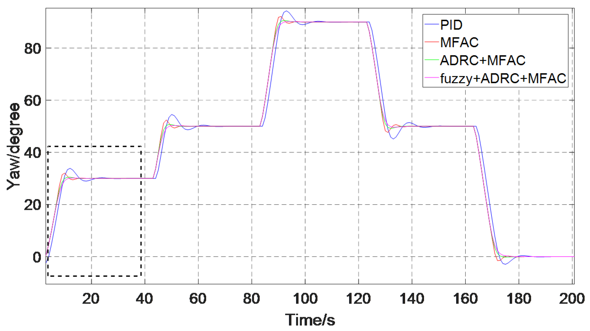
The heading control performance of PID and MFAC and MFAC based on ADRC as well as fuzzy optimized MFAC based on ADRC (blue, red, green, and pink) without current influence are given in Figure 12 and Figure 13.
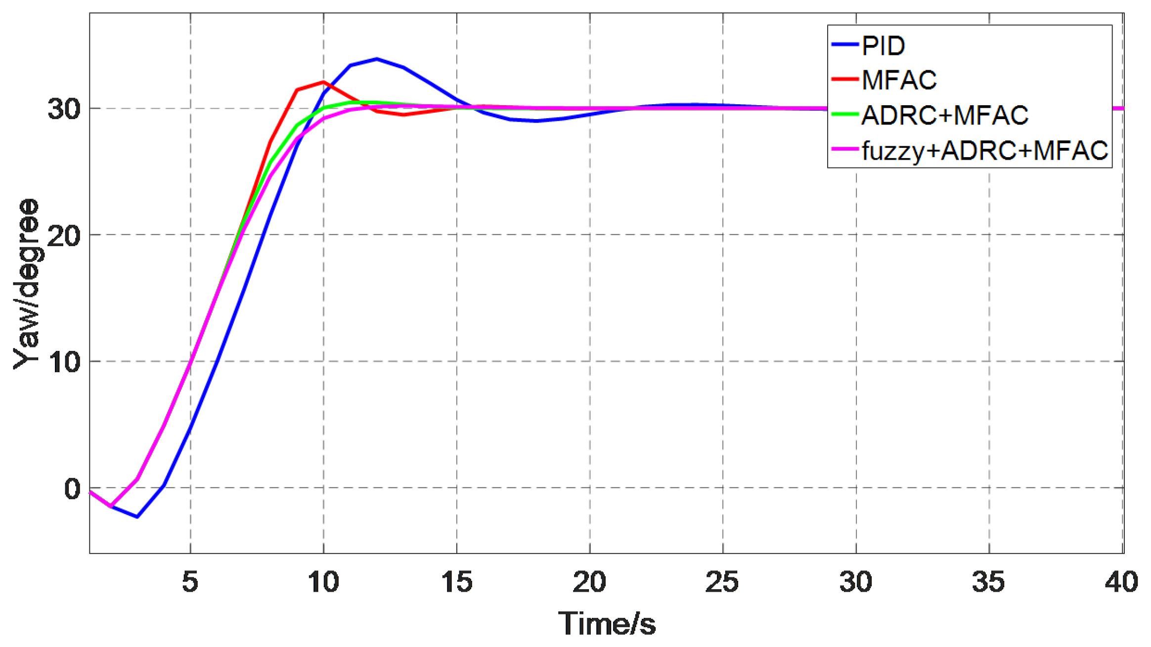
Figure 12 shows the control performance of these four control methods under different heading changes at different angles, and one group is selected for amplification in Figure 13 from 0 s to 40 s.
The control parameters of PID, MFAC, MFAC based on ADRC, and fuzzy optimized MFAC based on ADRC are adjusted to ensure that there is the best performance for each method.
According to Figure 13, we analyze the control effect from four aspects: overshoot, adjusting time, rising time, and steady-state error (SSE). In addition, Table 2 shows the effects of different control methods on overshoot, rising time, adjusting time, and steady-state error intuitively.
  • In terms of overshoot, the fuzzy optimized MFAC based on ADRC and the MFAC based on ADRC have no overshoot, the PID overshoot is more than MFAC, which is 0.46 degree, and the MFAC is 0.42 degree.
  • For the rising time, the MFAC based on ADRC as well as fuzzy optimized MFAC based on ADRC are less than PID as shown in Figure 13, which are 12 s. The PID is 13 s, and MFAC is shortest, which is 10 s.
  • The adjusting time of MFAC, MFAC based on ADRC, and fuzzy optimized MFAC based on ADRC are the same and the shortest are 13 s, and the adjusting time of PID is 20 s.
  • All these four methods have no steady-state error.
Through the analysis of Figure 12, the control effect of the following four groups of heading changes are the same as that of Group 1. In the case of no current interference, the fuzzy optimized MFAC based on ADRC and MFAC based on ADRC have the same control effect. Although their rising times are longer than MFAC, the adjusting time is the same as MFAC. Fuzzy optimized MFAC based on ADRC and MFAC based on ADRC have no overshoot compared with MFAC, and it can be seen to have better performance than MFAC. PID control effect is poor with a larger overshoot and a longer rising time and adjusting time.

b. Heading Control Performance with Current Influence

Figure 14 and Figure 15 show the control performance of these four methods with current influence. Figure 14 shows the control performance of the four control methods under different heading changes at different angles, and one group is selected for amplification in Figure 15 from 0 s to 40 s. In Figure 14, the control parameters of these four methods are the same as the parameters of methods without current influence.
According to Figure 15, we also analyze the control effect from four aspects: overshoot, adjusting time, rising time, and steady-state error. In addition, Table 3 shows the effects of different control methods on overshoot, rising time, adjusting time, and steady-state error respectively.
  • Regarding the overshoot, the PID has the largest overshoot, which is 3.9 degrees. MFAC and MFAC based on ADRC of overshoot decreasing successively, are 2.1 degrees, 1.1 degrees, respectively. Fuzzy optimized MFAC based on ADRC has no overshoot.
  • The rising time of MFAC, PID, and MFAC based on ADRC as well as fuzzy optimized MFAC based on ADRC increase respectively, which are 8 s, 9 s, 10 s, and 11 s.
  • The adjusting time of MFAC and MFAC based on ADRC and fuzzy optimized MFAC based on ADRC are the same and the shortest are 15 s; PID is 33 s.
  • All these four methods have no steady-state error.
Through the analysis of Figure 14, the control effect of the following four groups of heading changes are the same as that of group one. In the case of current interference, fuzzy optimized MFAC based on ADRC can be considered to have better performance with no overshoot and minimum adjusting time in the case of sacrificing a small amount of rising time.
According to these four pictures, it can be seen that the control methods of the four types all have a good control effect on the heading changes at different angles. Regardless of the presence or absence of ocean current disturbance, the fuzzy optimized MFAC based on ADRC has strongest anti-interference ability with shortest adjusting time as well as lowest overshoot. Fuzzy optimized MFAC based on ADRC algorithm can be considered to have better control effect and be superior to other control methods. In Figure 15, the velocity of AUV is 1.5 m/s, current velocity Uc is 0.5 m/s, and angle of current α is 45 degrees.

4.1.2. Heading Tracking

a. Heading Tracking without Current Influence

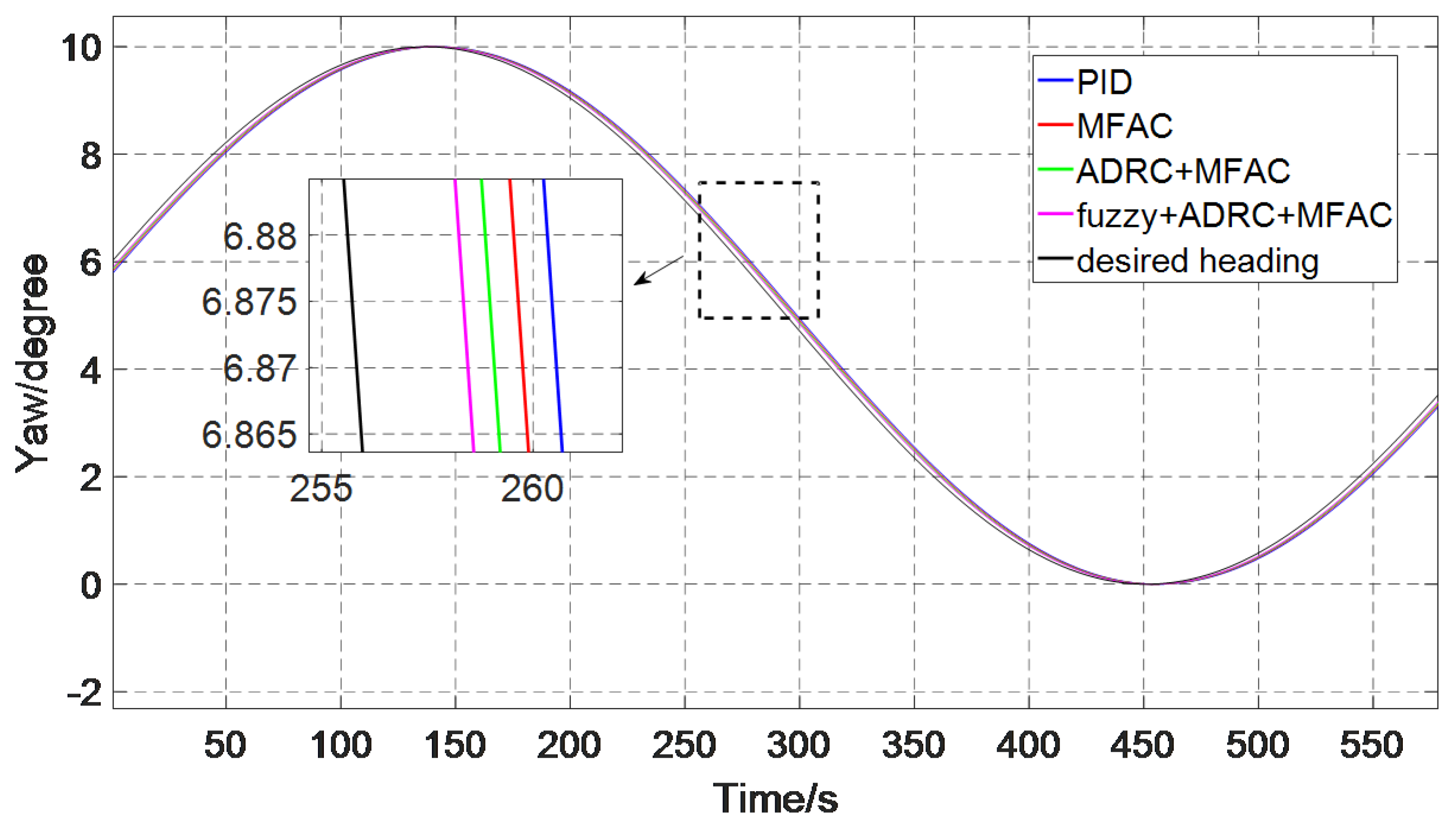
Figure 16 shows the heading tracking curves of the four control methods in the absence of current interference. It can be seen from the picture that all the four control methods can well track the heading changes. Fuzzy optimized MFAC based on ADRC due to its smallest RMSE (Root Mean Square Error), MAE (Mean Absolute Deviation) and RMS (Root Mean Square) between actual heading and desired heading proved that fuzzy optimized MFAC based on ADRC has a better tracking ability than other three methods. We analyze the control effect from three aspects: RMS, RMSE, and MAE. In addition, Table 4 shows the effects of different control methods on RMS, RMSE, and MAE, respectively.
RMSE and MAE are used to measure the difference between the desired value and the actual value. RMS can reflect the accuracy in process control. For tracking performance, the smaller of the RMSE and MAE values, the better the tracking effect, and the closer the RMS of the actual value is to the RMS of the desired value, the better the tracking performance. The calculation formulas of RMS, RMSE, and MAE are as follows:
R M S = 1 m i = 1 m ( y i ) 2
R M S E = 1 m i = 1 m ( y i x i ) 2
M A E = 1 m i = 1 m y i x i
where m is the number of samples, y i the desired value, x i the actual value.
  • Regarding the RMS, the RMS of the desired heading is 6.2204 degrees, and PID, MFAC, MFAC based on ADRC, and fuzzy optimized MFAC based on ADRC are 6.2354 degrees, 6.2326 degrees, 6.2307 degrees, and 6.2288 degrees. The optimized MFAC based on ADRC RMS is closest to the RMS of the desired heading.
  • The RMSE of PID, MFAC, MFAC based on ADRC, and fuzzy optimized MFAC based on ADRC are 0.1602 degrees, 0.1334 degrees, 0.1104 degrees, and 0.0891 degree. The fuzzy optimized MFAC based on ADRC has the smallest RMSE.
  • The MAE of PID, MFAC, MFAC based on ADRC as well as fuzzy optimized MFAC based on ADRC are 0.1388 degrees, 0.1137 degrees, 0.1003 degrees, and 0.0974 degrees. The fuzzy optimized MFAC based on ADRC has the smallest MAE.

b. Heading Tracking with Current Influence

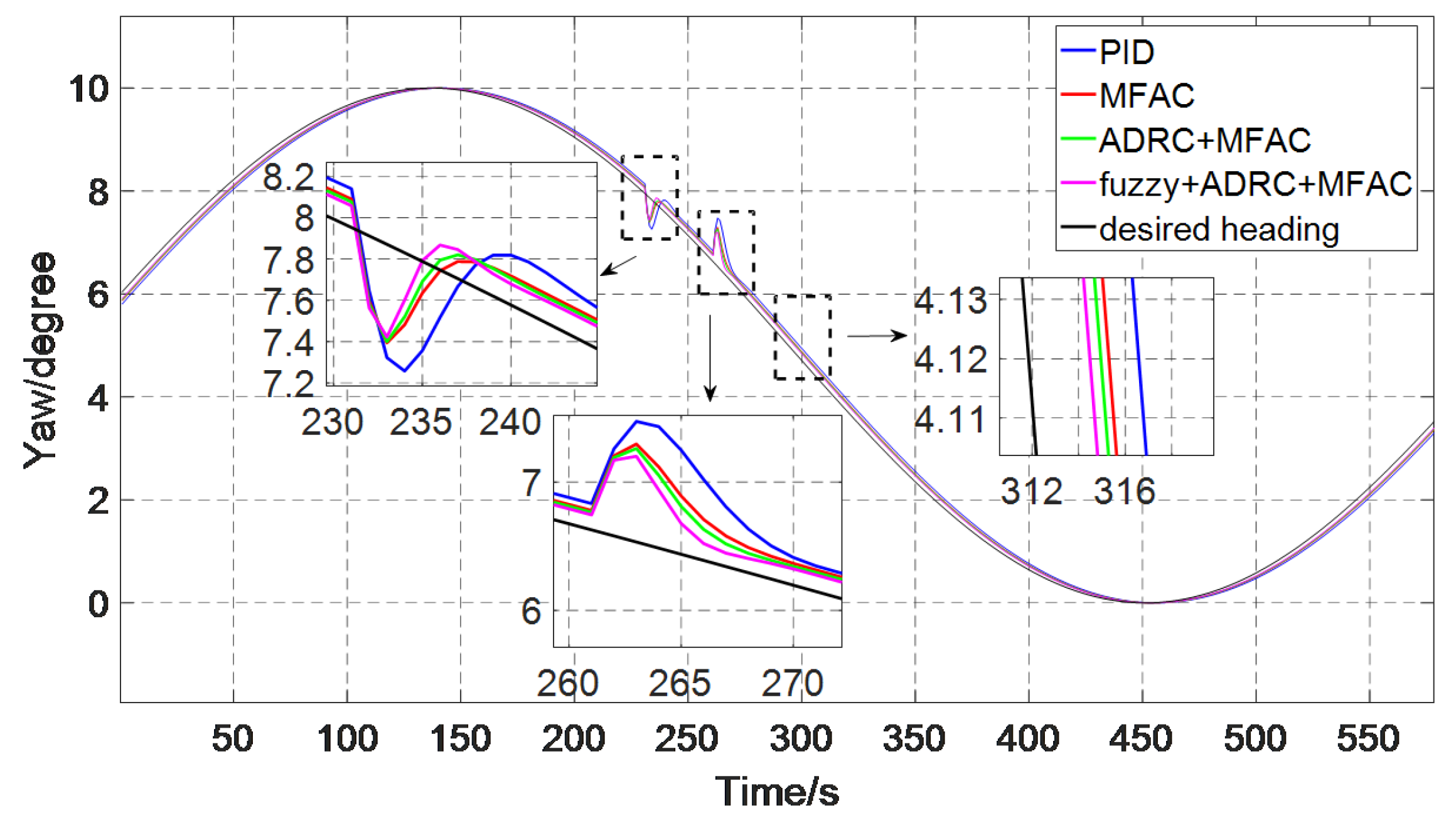
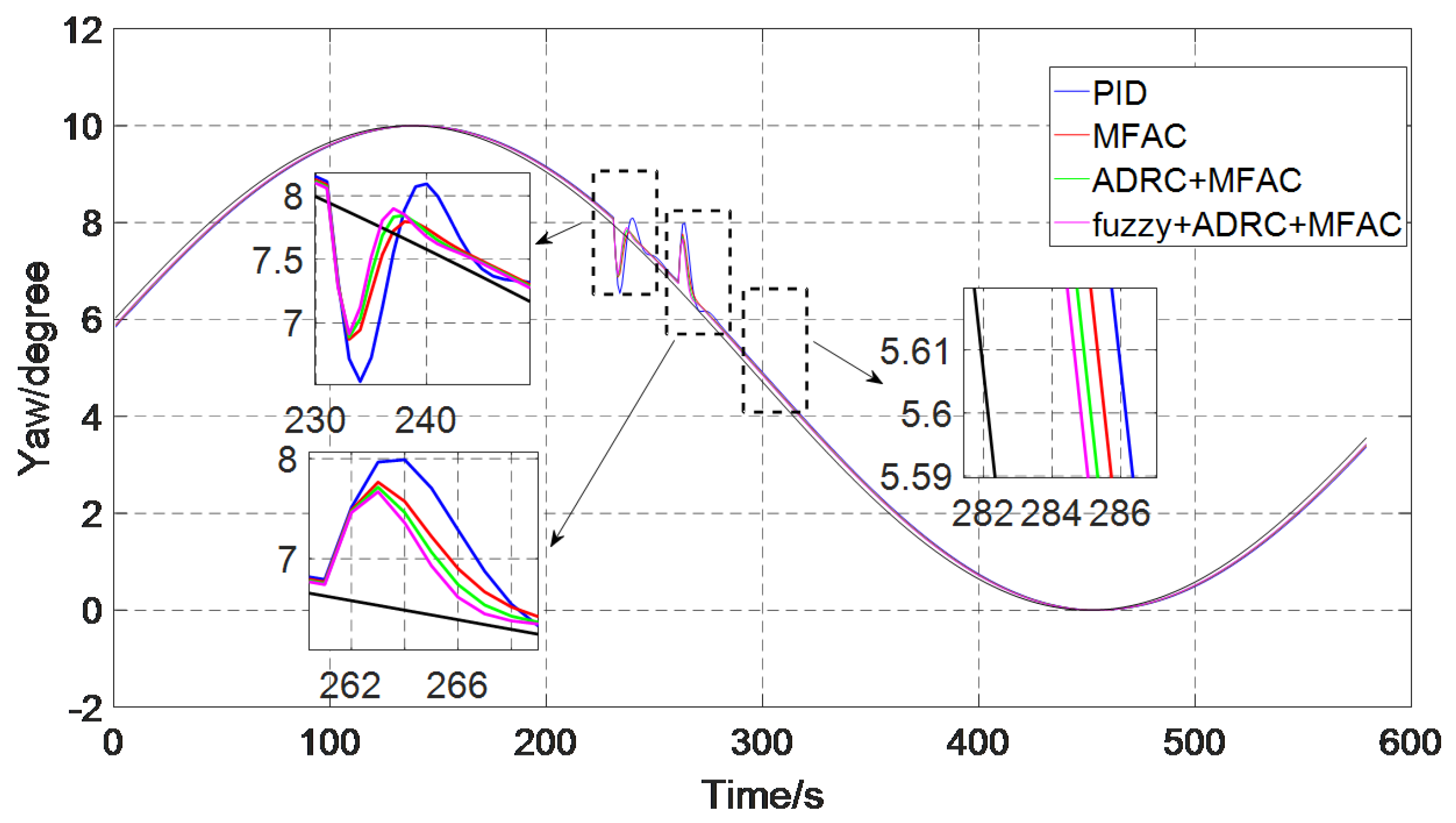
Figure 17 shows the heading tracking curves of the four control methods under the condition of current interference. From 250 s to 280 s, the current interference is added, the velocity of AUV is 1.5 m/s, current velocity Uc is 0.5 m/s, and angle of current α is 45 degrees. Due to the influence of current disturbance, the four control algorithms all have a large bias, but can be adjusted quickly to the desired heading. Among them, fuzzy optimized MFAC based on ADRC has smallest disturbance deviation and can be adjusted to the desired heading as soon as possible, which indicates that it has a fast tracking speed and strong anti-interference ability. We analyze the tracking performance of four control algorithms through the three aspects of RMS, RMSE, and MAE. In addition, Table 5 shows the effects of different control methods on RMS, RMSE, and MAE, respectively.
  • Regarding the RMS, the RMS of the desired heading is 6.2204 degrees, and PID, MFAC, MFAC based on ADRC, and fuzzy optimized MFAC based on ADRC are 6.2342 degrees, 6.2303 degrees, 6.2295 degrees, and 6.2283 degrees. The optimized MFAC based on ADRC RMS is closest to the RMS of the desired heading.
  • The RMSE of PID, MFAC, MFAC based on ADRC, and fuzzy optimized MFAC based on ADRC are 0.1799 degrees, 0.1299 degrees, 0.1176 degrees, and 0.1009 degrees. The fuzzy optimized MFAC based on ADRC has the smallest RMSE.
  • The MAE of PID, MFAC, MFAC based on ADRC, and fuzzy optimized MFAC based on ADRC are 0.1500 degrees, 0.1086 degrees, 0.0978 degrees and 0.0831 degrees. The fuzzy optimized MFAC based on ADRC has the smallest MAE.
Figure 18 shows the heading tracking curves of the four control methods under the condition of current interference. The velocity of AUV is 1.5 m/s, current velocity Uc is 0.4 m/s, and angle of current a is 45 degrees. From 250 s to 280 s, current velocity Uc is changed to 0.7 m/s. It can be seen from the figure that the control effect is consistent with Figure 17, four control methods can all track the change of the desired heading well. The fuzzy optimized MFAC based on ADRC proposed in this paper has smallest disturbance deviation and can be adjusted to the desired heading as soon as possible, which indicates that under the interference, when there is suddenly increased interference, fuzzy optimized MFAC based on ADRC also has a faster tracking speed and stronger anti-interference ability than others. We analyze the tracking performance of four control algorithms through the three aspects of RMS, RMSE, and MAE. In addition, Table 6 shows the effects of different control methods on RMS, RMSE, and MAE, respectively.
  • Regarding the RMS, the RMS of the desired heading is 6.2204 degrees, and PID, MFAC, MFAC based on ADRC, and fuzzy optimized MFAC based on ADRC are 6.2327 degrees, 6.2297 degrees, 6.2288 degrees, and 6.2281 degrees. The optimized MFAC based on ADRC RMS is closest to the RMS of desired heading.
  • The RMSE of PID, MFAC, MFAC based on ADRC, and fuzzy optimized MFAC based on ADRC are 0.2023 degrees, 0.1575 degrees, 0.1414 degrees, and 0.1297 degrees. The fuzzy optimized MFAC based on ADRC has the smallest RMSE.
  • The MAE of PID, MFAC, MFAC based on ADRC, and optimized MFAC based on ADRC are 0.1388 degrees, 0.1137 degrees, 0.1003 degrees, and 0.0974 degrees. The fuzzy optimized MFAC based on ADRC has the smallest MAE.
According to these three figures, it can be seen that the control methods of the four types all have a good tracking effect on the heading tracking. In the case of current interference or not, the fuzzy optimized MFAC based on ADRC has strongest anti-interference ability with the shortest RMSE, MAE and RMS error between desired heading, and actual heading. Fuzzy optimized MFAC based on ADRC algorithm can be considered to have better tracking effect and to be superior to other control methods.

4.2. Experiment

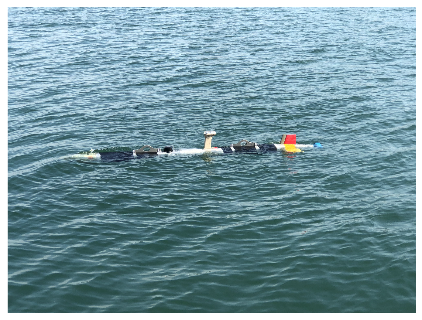
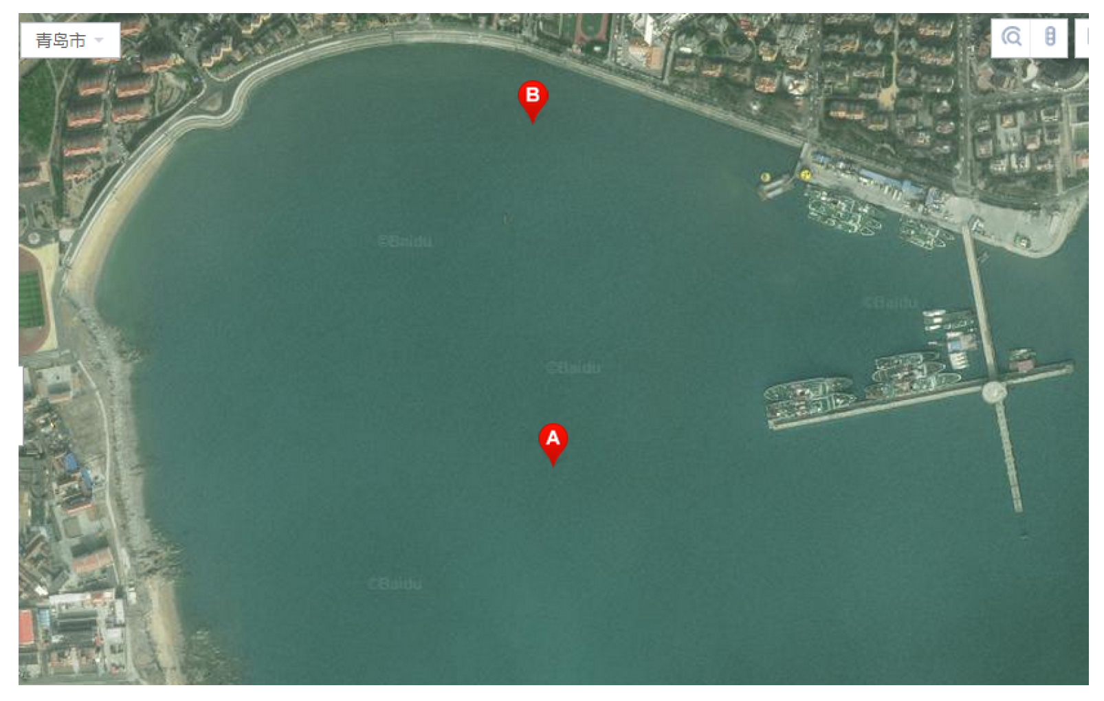
The proposed method is experimented on the Sailfish AUV—a kind of torpedo underwater vehicle independently developed at the Underwater Vehicle Lab of the Ocean University of China. The Sailfish AUV displacement is 260 kg. It measures 360 cm in length, 324 mm in diameter. Figure 19 is the Sailfish AUV, and Figure 20 is the experimental area.
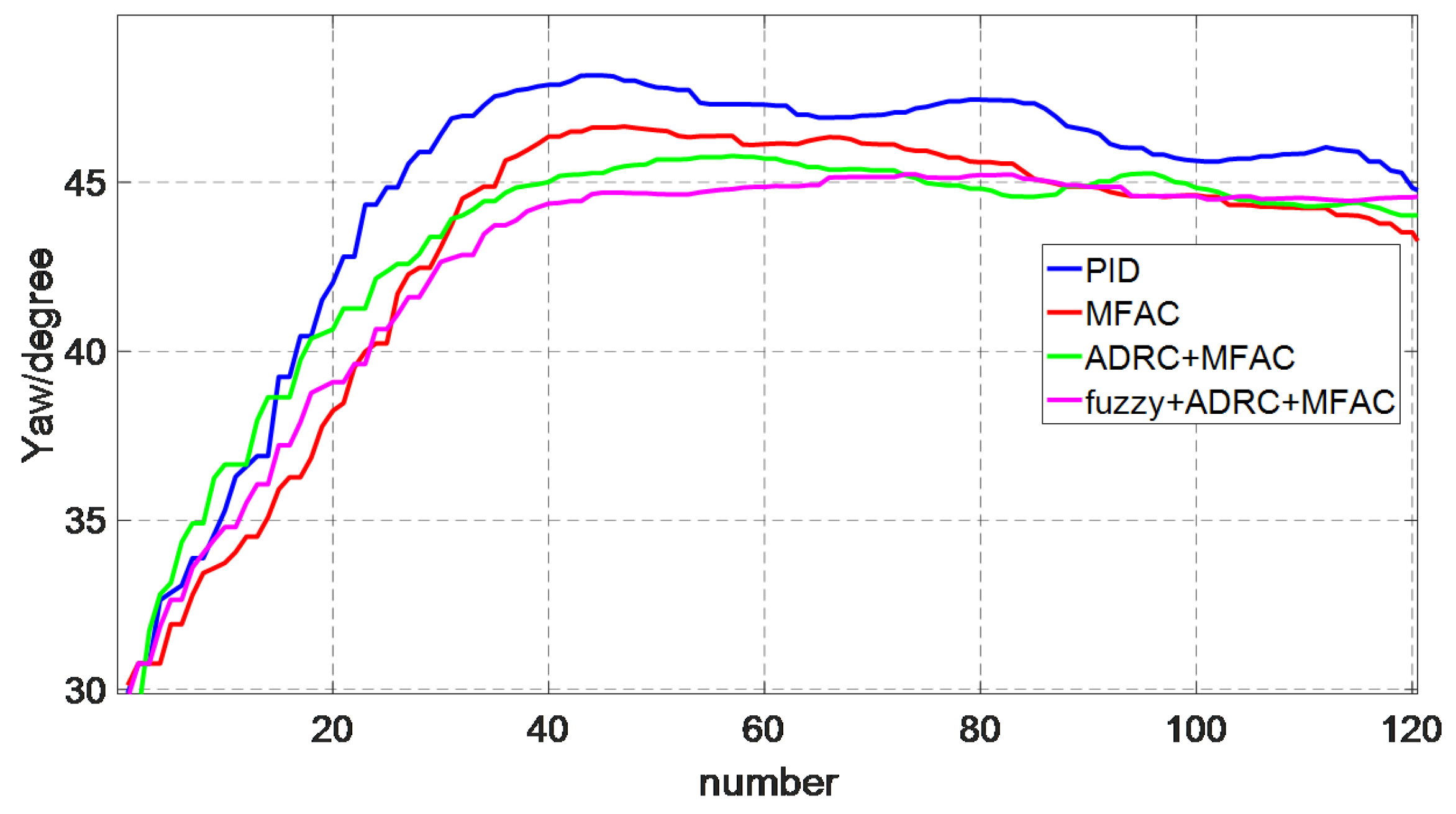
To verify the effectiveness of the controller designed above, some trails were carried out in Tuandao lake near Qingdao in March 2019, with a sunny day and sea condition grade 3. The desired speed was 0.5 m/s. The experimental effects of these four controls in the lake are shown in Figure 21, Figure 22, Figure 23, Figure 24, Figure 25, Figure 26, Figure 27, Figure 28, Figure 29, Figure 30, Figure 31, Figure 32, Figure 33 and Figure 34. The x-coordinate is the number of times, and the heading is updated four times a second. The y-coordinate represents the current heading.

4.2.1. Heading Change

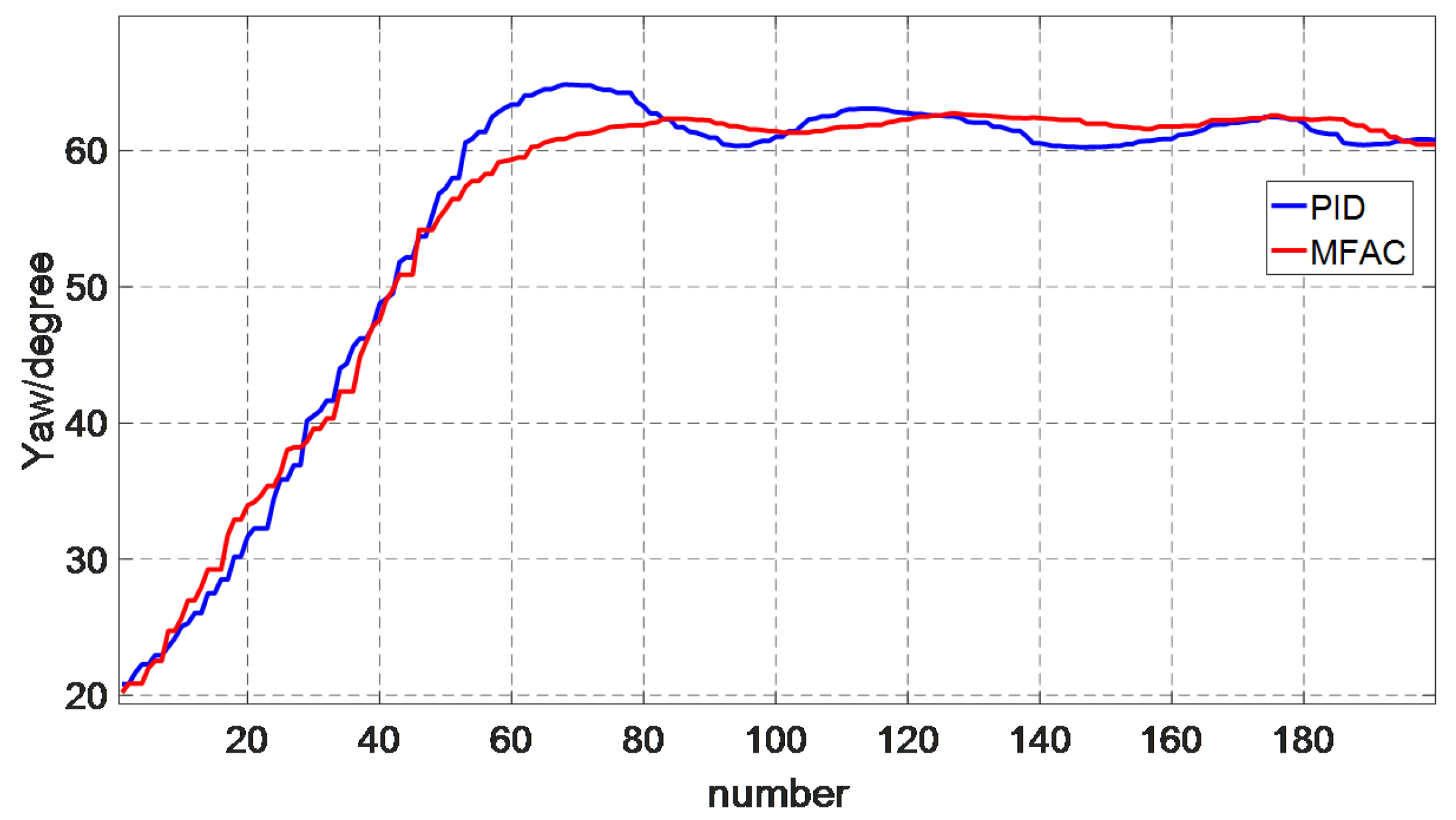
We choose two heading changes to test the control performance. Once heading change is from 20 degrees to 60 degrees, the second is from 30 degrees to 45 degrees.
Figure 21, Figure 22, Figure 23 and Figure 24 shows the control performance of PID and MFAC. The results are reported in Table 7 and Table 8. We analyze the control effects from five aspects: overshoot, rising time steady-state error RMS, and RMSE. In addition, Table 7 shows the effects of different control methods on overshoot, rising time steady-state error, RMS, and RMSE, respectively.
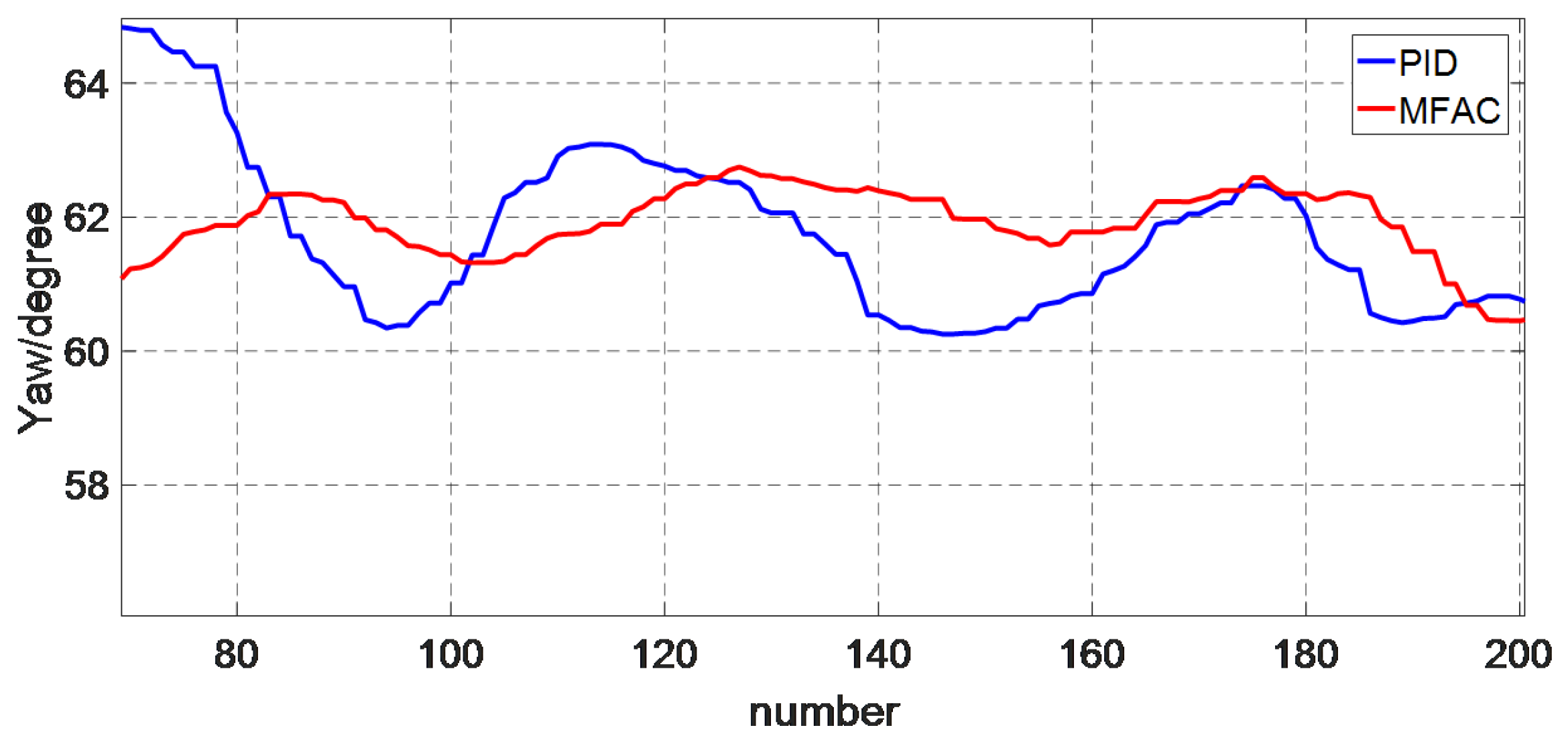
1. Figure 21 and Figure 22 are the heading change from 20 degrees to 60 degrees.
  • In terms of overshoot, MFAC overshoot is less than PID. The overshoot of PID is 4.86 degrees and the MFAC is 2.26 degrees.
  • For the rising time, the MFAC is longer than PID showed in Figure 21, the rising time of PID is 13 s and MFAC is 16 s.
  • Regarding steady-state error, MFAC can better stabilize near the desired heading. The steady-state error of MFAC is 1.30 degrees, and PID is 2.25 degrees.
  • From 70 to 180 times, heading begins to stabilize, the RMS and RMSE of PID are 62.1085 degrees and 0.2267 degrees. MFAC RMS is closer to the desired heading than PID, and RMSE of MFAC is less than PID; the RMS of MFAC is 61.9758 degrees and the RMSE of MFAC is 0.1854 degrees.
The effectiveness of MFAC control method is proved with smaller overshoot and steady-state error, although the rising time of MFAC is longer than PID.
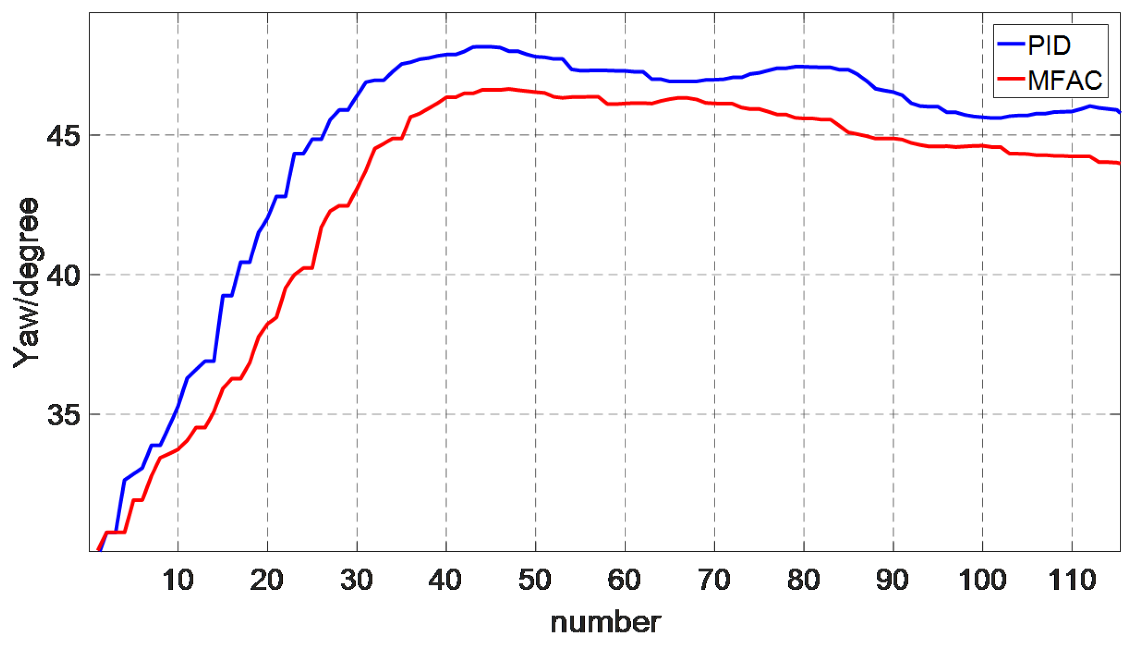
2. The desired heading is 45 degrees, the current heading is 30 degrees in Figure 23 and Figure 24.
  • In terms of overshoot, MFAC overshoot is 1.62 degrees and less than PID, the PID is 3.16 degrees.
  • For the rising time, the MFAC is longer than PID, which are 7 s, 9 s, respectively.
  • Regarding steady-state error, MFAC can also better stabilize near the desired heading. The steady-state error of MFAC is 0.55 degree, and PID is 1.66 degrees.
  • From 40 to 110 times, heading begins to stabilize, the RMS and RMSE of PID are 46.7114 degrees and 1.7007 degrees. MFAC RMS is closer to the desired heading than PID and RMSE of MFAC is less than PID, the RMS of MFAC is 45.3448 degrees and the RMSE of MFAC is 0.3448 degree.
This result can also prove the effectiveness of MFAC control method.
These four pictures can verify that the control performance of MFAC is better than PID with simple structure, high reliability as well as easy implementation.
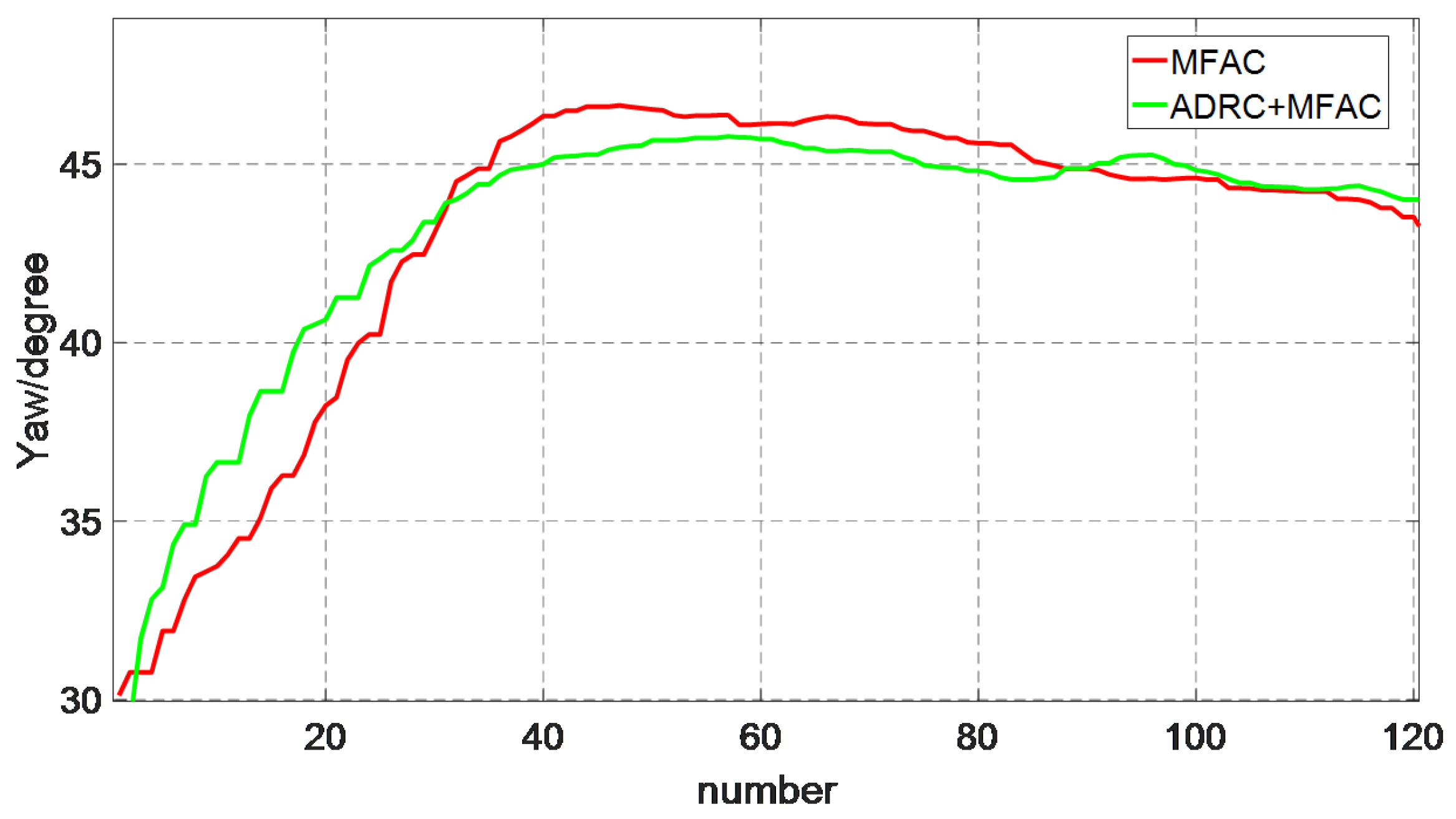
Figure 25, Figure 26, Figure 27 and Figure 28 show the control performances of MFAC and MFAC based on ADRC. The results are reported in Table 9 and Table 10.
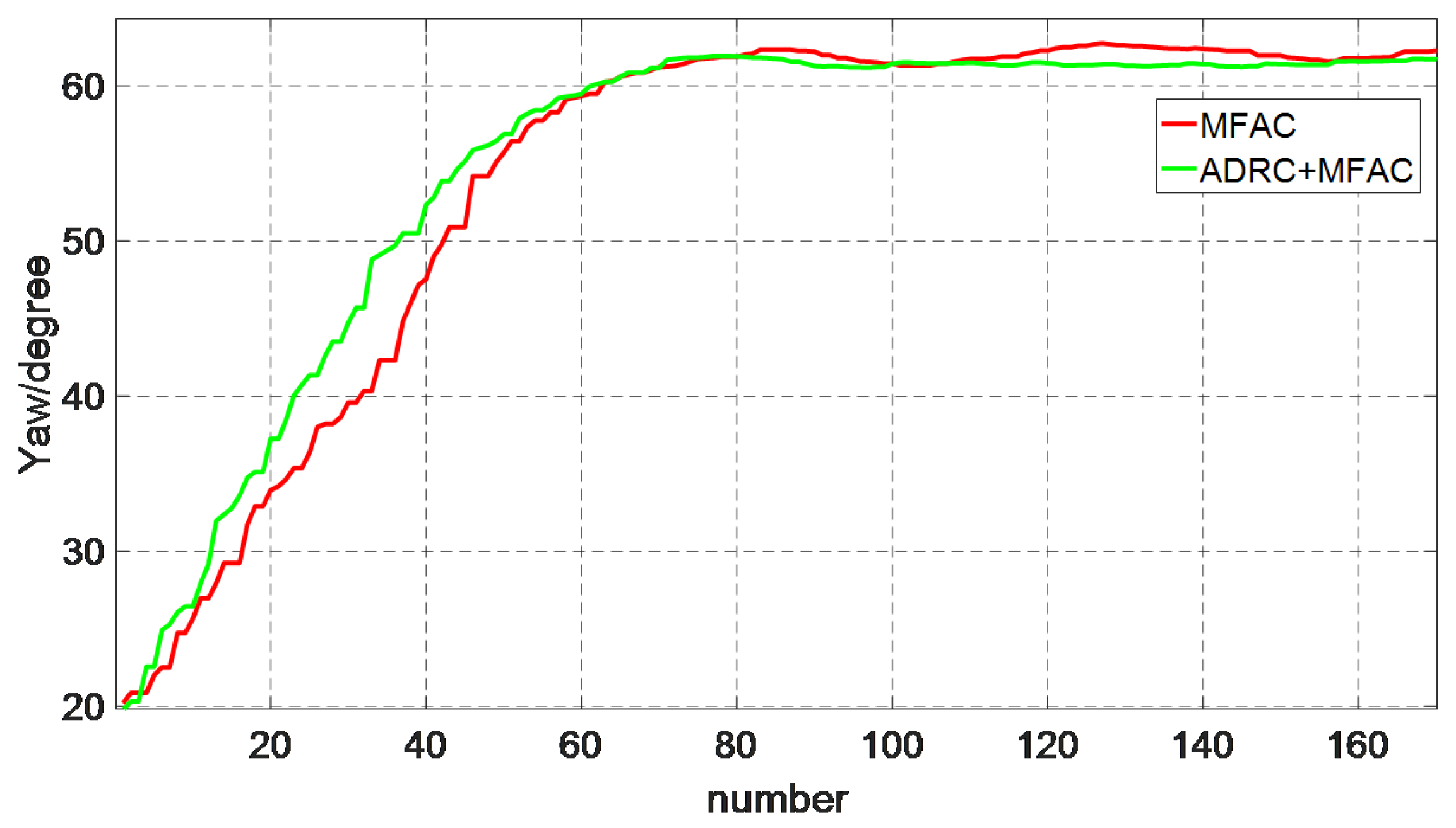
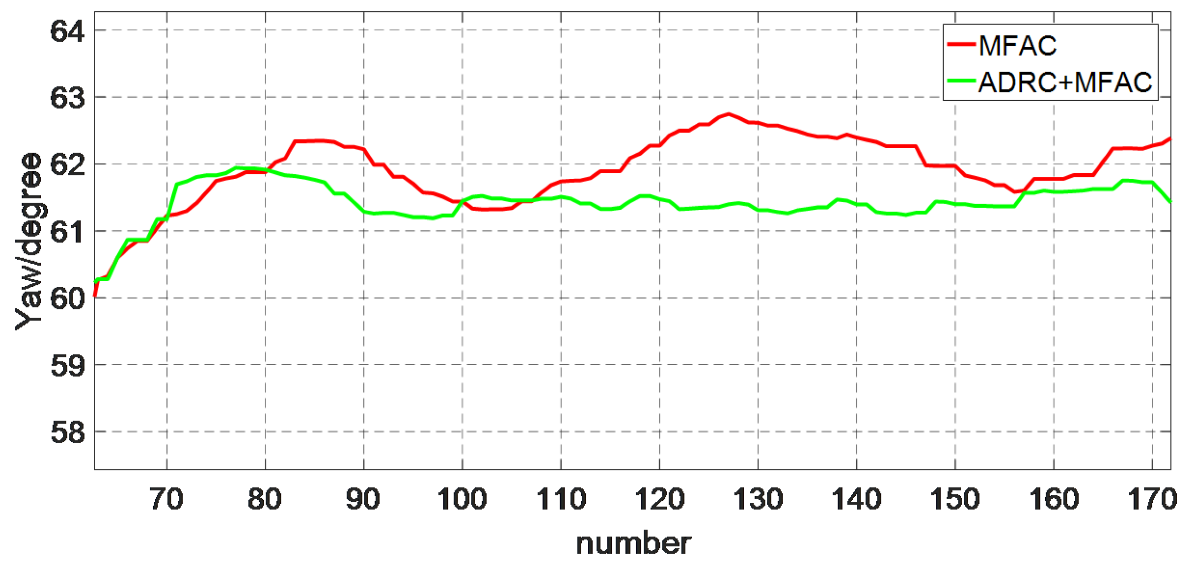
1. Figure 25 and Figure 26 are the heading change from 20 degrees to 60 degrees.
  • In terms of overshoot, MFAC based on ADRC overshoot is less than MFAC. The overshoot of MFAC is 2.26 degrees and the MFAC based on ADRC is 1.81 degrees.
  • For the rising time, the MFAC is longer than MFAC based on ADRC showed in Figure 25, the MFAC is 16 s, and MFAC based on ADRC is 15 s.
  • Regarding steady-state error, MFAC and MFAC based on ADRC can both stabilize near the desired heading. The steady-state error of MFAC and MFAC based on ADRC are 1.30 degrees.
  • From 70 to 180 times, heading begins to stabilize, the RMS of MFAC based on ADRC is 61.3107 degrees, which is closer to the desired heading than MFAC; the RMSE of MFAC based on ADRC is smaller, which is 0.1285 degrees.
The performance of MFAC based on ADRC control method is proved to be better than MFAC.
2. The desired heading is 45 degrees, the current heading is 30 degrees in Figure 27 and Figure 28.
  • In terms of overshoot, MFAC based on ADRC overshoot is 0.74 degree and less than MFAC, the MFAC is 1.62 degrees.
  • Regarding the rising time, the MFAC based on ADRC is longer than MFAC, which are 9 s and 10 s, respectively.
  • Regarding steady-state error, MFAC based on ADRC can better stabilize near the desired heading. The steady-state error of MFAC based on ADRC is 0.35 degrees, while MFAC is 0.55 degrees.
  • From 40 to 110 times, heading begins to stabilize, the RMS of MFAC based on ADRC is 44.7329 degrees closer to the desired heading than MFAC; the RMSE of MFAC based on ADRC is smaller, which is 0.2682 degrees.
The performance of MFAC based on ADRC control method also is proved to be better than MFAC.
These four pictures can verify MFAC based on ADRC has better control performance compared with MFAC, which has a better anti-interference capability.
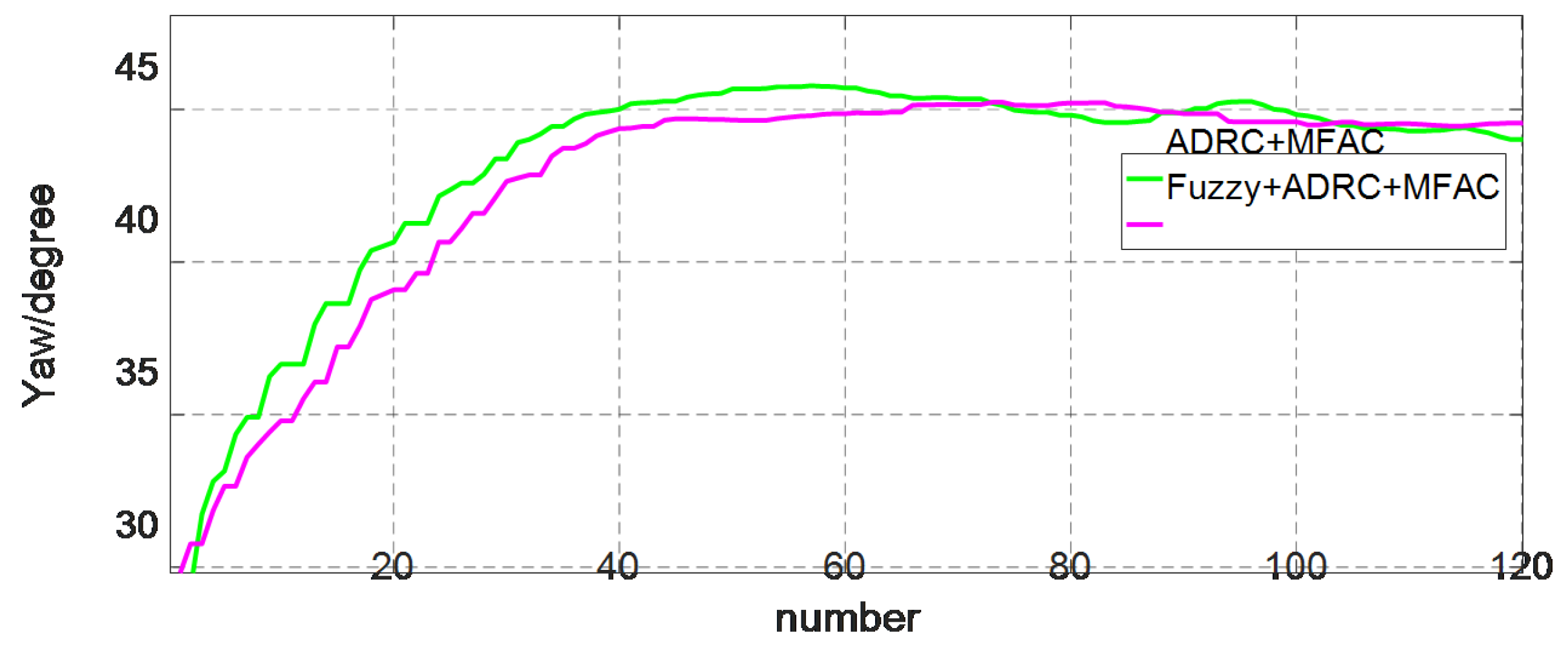
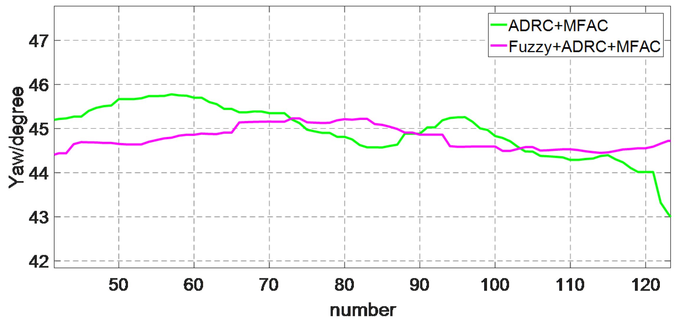
Figure 29, Figure 30, Figure 31 and Figure 32 show the control performance of MFAC based on ADRC and fuzzy optimized MFAC based on ADRC. The results are reported in Table 11 and Table 12.
1. Figure 29 and Figure 30 are the heading change from 20 degrees to 60 degrees.
  • In terms of overshoot, fuzzy optimized MFAC based on ADRC overshoot is less than MFAC based on ADRC. The overshoot of fuzzy optimized MFAC based on ADRC is 0.51 degrees and the MFAC based on ADRC is 1.81 degrees.
  • For the rising time, the MFAC and fuzzy optimized MFAC based on ADRC are the same as shown in Figure 29, which are 15 s.
  • Regarding steady-state error, fuzzy optimized MFAC based on ADRC can better stabilize near the desired heading. The steady-state error of MFAC based on ADRC is 1.3 degrees, and fuzzy optimized MFAC based on ADRC has no steady-state error.
  • From 70 to 180 times, the heading begins to stabilize; the RMS and RMSE of fuzzy optimized MFAC based on ADRC are 60.1255 degrees and 0.0292 degree. MFAC based on ADRC RMSE is larger than the fuzzy optimized MFAC based on ADRC. The RMS of fuzzy optimized MFAC based on ADRC is closest to the desired heading.
This result can also prove the effectiveness of fuzzy optimized MFAC based on ADRC control method.
2. The desired heading is 45 degrees, the current heading is 30 degrees in Figure 31 and Figure 32.
  • In terms of overshoot, fuzzy optimized MFAC based on ADRC overshoot is 0.23 degrees and less than MFAC based on ADRC, the MFAC based on ADRC is 0.74 degrees.
  • For the rising time, the MFAC based on ADRC is 10s and fuzzy optimized MFAC based on ADRC is 11 s.
  • Regarding steady-state error, fuzzy optimized MFAC based on ADRC can better stabilize near the desired heading. The steady-state error of MFAC based on ADRC is 0.35 degrees, and the fuzzy optimized MFAC based on ADRC has no steady-state error.
  • From 40 to 110 times, the heading begins to stabilize; the RMS of the fuzzy optimized MFAC based on ADRC is 44.9064 degrees most close to the desired heading, and RMSE of fuzzy optimized MFAC based on ADRC is 0.0980 degrees, which is smaller than MFAC based on ADRC.
It can also prove the effectiveness of fuzzy optimized MFAC based on ADRC control method with smaller overshoot and steady-state error.
These four pictures can verify that the fuzzy optimized MFAC based on ADRC has better control performance compared with MFAC based on ADRC, which has better anti-interference capability and stronger stability.
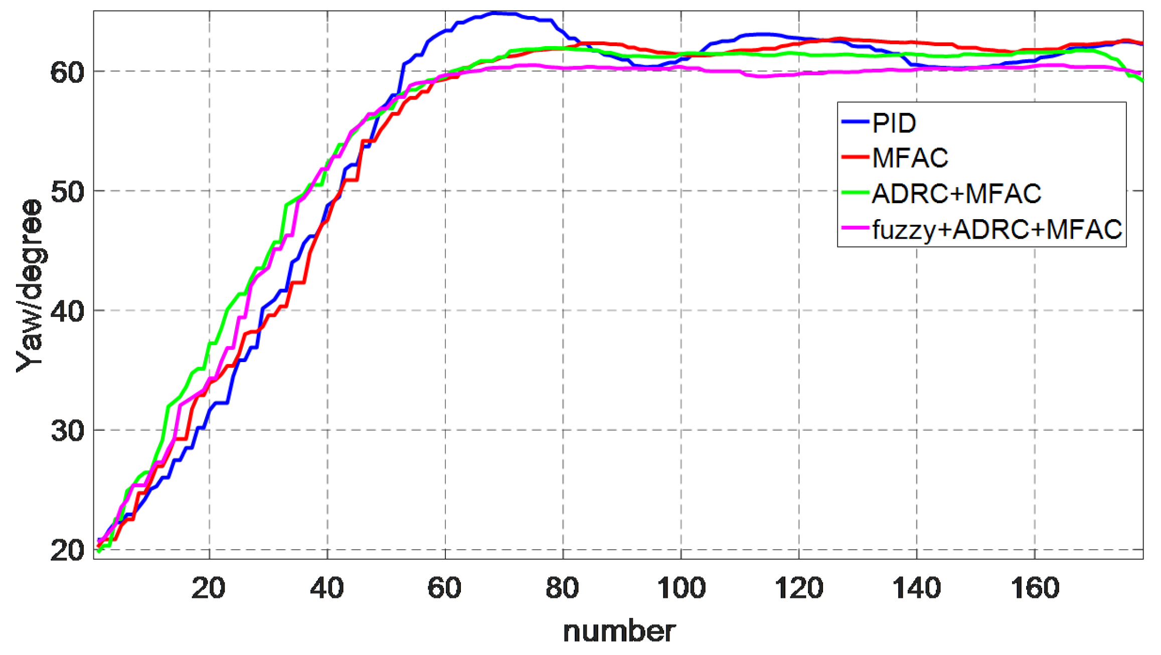
The following two pictures contain four control methods with different heading changes. Table 13 and Table 14 are comparison of these four methods with experimental data.
Form these two pictures, it can be seen that the control method this paper proposed—fuzzy optimized MFAC based on ADRC—has the best performance with the lowest overshoot as well as minimum steady-state error. By analyzing the RMS and RMSE, the fuzzy optimized MFAC based on ADRC performs better than others. This proves that fuzzy optimized MFAC based on ADRC has the best anti-interference capability and high reliability with simple structure and easy implementation.

4.2.2. Heading Tracking

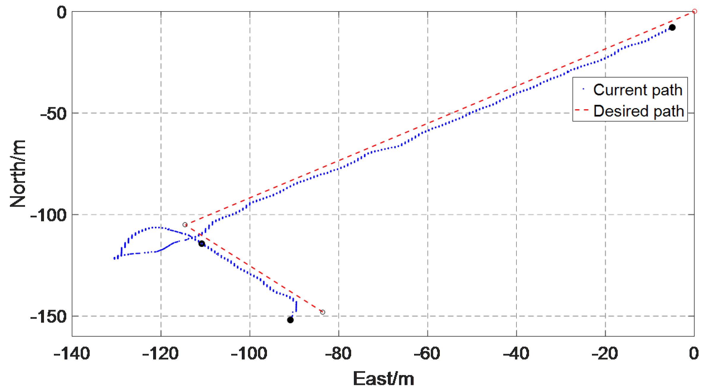
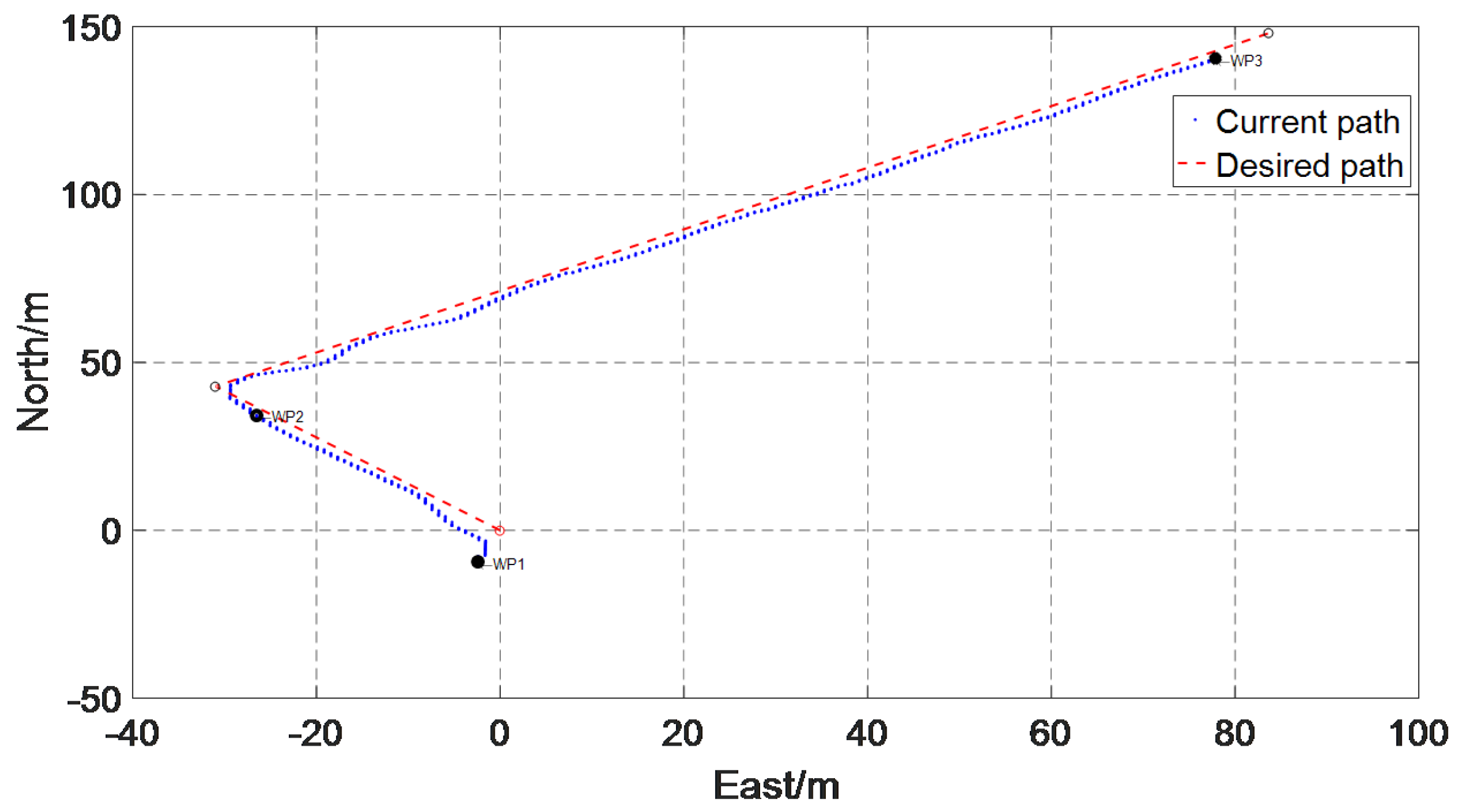
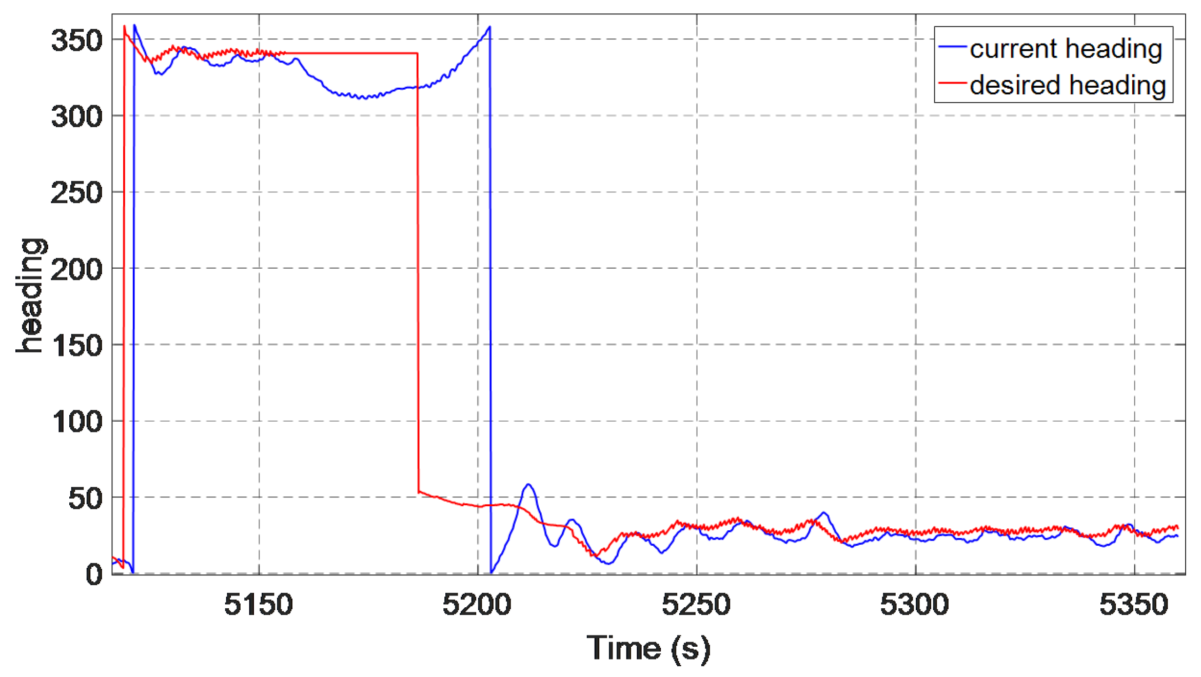
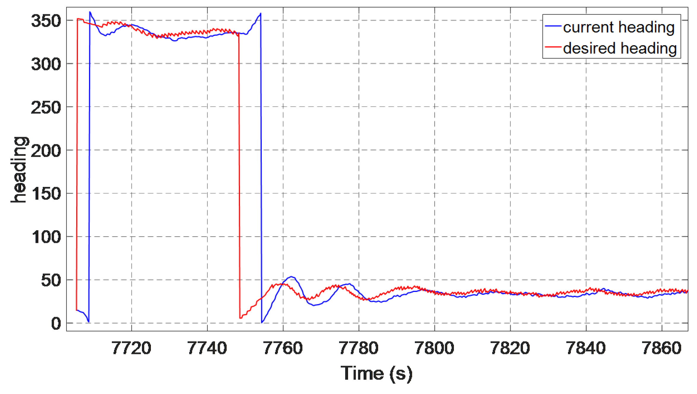
Figure 35 and Figure 36 show the path-tracking curve of PID and fuzzy optimized MFAC based on ADRC. The expected path is a right-angle linear tracking curve, the PID and proposed method both can track the path well. In addition, Figure 37 and Figure 38 are the heading tracking curves for PID and fuzzy optimized MFAC based on ADRC. We analyze the control effect from three aspects: RMS error between desired heading and actual heading, RMSE, and MAE. In addition, Table 15 shows the effects of different control methods on RMS error between desired heading and actual heading, RMSE, and MAE respectively.
  • Regarding the RMS error, the RMS error of PID is 2.975 degrees fuzzy optimized MFAC based on ADRC is 1.8139 degrees.
  • The RMSE of PID as well as fuzzy optimized MFAC based on ADRC are 5.7962 degrees and 5.6868 degrees. The fuzzy optimized MFAC based on ADRC has the smallest RMSE.
  • The MAE of PID and fuzzy optimized MFAC based on ADRC are 4.8083 degrees and 4.3539 degrees. The fuzzy optimized MFAC based on ADRC has the smallest MAE.
As can be seen from the two figures, both control methods can track the heading change. Fuzzy optimized MFAC based on ADRC due to its smallest RMSE, MAE, and RMS between actual heading and desired heading proves that fuzzy optimized MFAC based on ADRC has better tracking ability.

5. Conclusions

In this paper, a fuzzy optimized MFAC based on the ADRC algorithm for AUV heading control is investigated. First, MFAC is proposed. Then MFAC based on ADRC is designed. The TD of ADRC tracks the desired heading to the input of MFAC. The ESO of ADRC applies the disturbance estimation to the output variable of MFAC. Simulations show that the MFAC based on ADRC has better robustness, accuracy, and rationality than PID and MFAC. Next, the fuzzy control is designed to tune coefficients. In heading control, fuzzy optimized MFAC based on ADRC algorithm shows better control performance than the other three control methods, with fastest rising time and adjusting time, and lowest overshoot. Experiments and simulations show that the fuzzy optimized MFAC based on ADRC algorithm has advantages of fast regulation, strong anti-interference ability, and so on. Compared with PID, MFAC, and MFAC based on ADRC, the proposed method is expected to reduce disturbance. Therefore, the correctness and effectiveness of the method are proved.
  • We analyze these four control methods concretely from the simulations:
    In heading control, regardless of the presence or absence of ocean current disturbance, the control performance about overshoot, rising time, adjusting time, steady-state error, RMS, RMSE, and MAE have the following characteristics:
    (a)
    Regarding the overshoot, the PID has the largest overshoot. The overshoot of MFAC and MFAC based on ADRC decreases successively. In addition, the fuzzy optimized MFAC based on ADRC has no overshoot.
    (b)
    The rising time of fuzzy optimized MFAC based on ADRC is longer than MFAC.
    (c)
    The adjusting time of MFAC and MFAC based on ADRC and fuzzy optimized MFAC based on ADRC is the same and less than PID.
    (d)
    All these four methods have no steady-state error.
    (e)
    The RMS of fuzzy optimized MFAC based on ADRC is closer to the desired heading than others. In addition, the RMSE and MAE of fuzzy optimized MFAC based on ADRC is the minimum.
    (f)
    The fuzzy optimized MFAC based on ADRC has a best heading tracking ability.
    Simulations proved that fuzzy optimized MFAC based on ADRC algorithm are best in terms of feasibility and efficiency.
  • We analyze these four control methods concretely from the experiments:
    In heading control, regardless of the presence or absence of ocean current disturbance, the control performance of overshoot, rising time, steady-state error, RMS, and RMSE have the following characteristics:
    (a)
    Regarding the overshoot, the PID has the largest overshoot. The overshoot of MFAC and MFAC based on ADRC decreases successively. In addition, the fuzzy optimized MFAC based on ADRC has the lowest overshoot.
    (b)
    As for rising time, the average rising time of fuzzy optimized MFAC based on ADRC is slightly longer than others.
    (c)
    The PID has the largest steady-state error. The steady-state error of MFAC and MFAC based on ADRC decreases successively. In addition, the fuzzy optimized MFAC based on ADRC has no steady-state error.
    (d)
    The RMS of fuzzy optimized MFAC based on ADRC is closer to the desired heading than others. In addition, the RMSE and MAE of fuzzy optimized MFAC based on ADRC is the minimum.
    (e)
    The fuzzy optimized MFAC based on ADRC has better heading tracking ability.
    Experiments proved that fuzzy optimized MFAC based on ADRC algorithm is best in terms of feasibility and efficiency.

Author Contributions

H.L. contributed in the bibliographic research and the structuring of the article and carry out test verification as well as writing the first draft; Y.S. is the corresponding author of this paper and contributed in the structuring of the article; B.H. contributed in the bibliographic research; Q.Y. contributed the validation of the information and the images and tables; X.M., J.Z., J.W., and D.W. contributed with proofreading.

Funding

This work is partially supported by The Natural Key Research and Development Program of China (2016YFC0301400) and Natural Science Foundation of China (51379198).

Conflicts of Interest

The authors declare no conflict of interest.

References

  1. Shen, Y.; Shao, K.; Ren, W.; Liu, Y. Diving control of autonomous underwater vehicle based on improved active disturbance rejection control approach. Neurocomputing 2016, 173, 1377–1385. [Google Scholar] [CrossRef]
  2. Wan, J.; He, B.; Shen, Y.; Liu, W.; Ding, X.; Gao, S. Heading multi-mode control based on soft-switching for autonomous underwater vehicle. Ocean Eng. 2018, 164, 672–682. [Google Scholar] [CrossRef]
  3. Li, H.; Ning, X.; Li, W. Implementation of a MFAC based position sensorless drive for high speed BLDC motors with nonideal back EMF. ISA Trans. 2017, 67, 348–355. [Google Scholar] [CrossRef]
  4. Xu, D.; Song, X.; Yan, W.; Jiang, B. Model-Free Adaptive Command-Filtered-Backstepping Sliding Mode Control for Discrete-Time High-Order Nonlinear Systems. Inf. Sci. 2019, 485, 141–153. [Google Scholar] [CrossRef]
  5. Li, Z.; Ding, Z.; Wang, M.; Oko, E. Model-free adaptive control for MEA-based post-combustion carbon capture processes. Fuel 2018, 224, 637–643. [Google Scholar] [CrossRef] [Green Version]
  6. Dong, N.; Feng, Y.; Han, X.S.; Wu, A.G. An Improved Model-free Adaptive Predictive Control Algorithm For Nonlinear Systems With Large Time Delay. In Proceedings of the 2018 IEEE 7th Data Driven Control and Learning Systems Conference (DDCLS), Enshi, China, 25–27 May 2018; pp. 60–64. [Google Scholar]
  7. Liu, D.; Yang, G.H. Neural network-based event-triggered MFAC for nonlinear discrete-time processes. Neurocomputing 2018, 272, 356–364. [Google Scholar] [CrossRef]
  8. Hui, Y.; Zhang, S.; Chi, R.; Bu, X. A New Model-Free Adaptive Control with an Extended State Observer. In Proceedings of the 2018 37th Chinese Control Conference (CCC), Wuhan, China, 25–27 July 2018; pp. 7992–7995. [Google Scholar]
  9. Hou, Z.; Bu, X. Model free adaptive control with data dropouts. Expert Syst. Appl. 2011, 38, 10709–10717. [Google Scholar] [CrossRef]
  10. Huang, Z.; Zheng, H.; Wang, S.; Liu, Y.; Ma, J.; Liu, Y. A self-searching optimal ADRC for the pitch angle control of an underwater thermal glider in the vertical plane motion. Ocean Eng. 2018, 159, 98–111. [Google Scholar] [CrossRef]
  11. Chen, T.; Zhang, W.; Zhou, J.; Yu, H.; Liu, X.; Hao, Y. Depth control of AUV using active disturbance rejection controller. In Proceedings of the 33rd Chinese Control Conference, Nanjing, China, 28–30 July 2014; pp. 7948–7952. [Google Scholar]
  12. Xu, J.; Zhou, J.; Zhang, H.; Bian, X. Auto disturbance rejection control system of diving for an underactuated AUV. In Proceedings of the 2011 Fourth International Joint Conference on Computational Sciences and Optimization, Yunnan, China, 15–19 April 2011; pp. 982–986. [Google Scholar]
  13. Xue, W.; Bai, W.; Yang, S.; Song, K.; Huang, Y.; Xie, H. ADRC with adaptive extended state observer and its application to air–fuel ratio control in gasoline engines. IEEE Trans. Ind. Electron. 2015, 62, 5847–5857. [Google Scholar] [CrossRef]
  14. Lotufo, M.A.; Colangelo, L.; Perez-Montenegro, C.; Canuto, E.; Novara, C. UAV quadrotor attitude control: An ADRC-EMC combined approach. Control Eng. Pract. 2019, 84, 13–22. [Google Scholar] [CrossRef]
  15. Luo, S.; Sun, Q.; Wu, W.; Sun, M.; Chen, Z.; He, Y. Accurate flight path tracking control for powered parafoil aerial vehicle using ADRC-based wind feedforward compensation. Aerosp. Sci. Technol. 2019, 84, 904–915. [Google Scholar] [CrossRef]
  16. Sun, J.; Pu, Z.; Yi, J. Conditional disturbance negation based active disturbance rejection control for hypersonic vehicles. Control Eng. Pract. 2019, 84, 159–171. [Google Scholar] [CrossRef]
  17. Su, Z.Q.; Zhou, M.; Han, F.F.; Zhu, Y.W.; Song, D.L.; Guo, T.T. Attitude control of underwater glider combined reinforcement learning with active disturbance rejection control. J. Mar. Sci. Technol. 2018, 1–19. [Google Scholar] [CrossRef]
  18. Zhong, Z.; Zhu, Y.; Ahn, C.K. Reachable set estimation for Takagi-Sugeno fuzzy systems against unknown output delays with application to tracking control of AUVs. ISA Trans. 2018, 78, 31–38. [Google Scholar] [CrossRef] [PubMed]
  19. Zhang, C.; Zou, W.; Cheng, N.; Gao, J. Trajectory tracking control for rotary steerable systems using interval type-2 fuzzy logic and reinforcement learning. J. Frankl. Inst. 2018, 355, 803–826. [Google Scholar] [CrossRef]
  20. Patre, B.; Londhe, P.; Waghmare, L.; Mohan, S. Disturbance estimator based non-singular fast fuzzy terminal sliding mode control of an autonomous underwater vehicle. Ocean Eng. 2018, 159, 372–387. [Google Scholar] [CrossRef]
  21. Li, X.; Wen, H.; Hu, Y.; Jiang, L. A novel beta parameter based fuzzy-logic controller for photovoltaic MPPT application. Renew. Energy 2019, 130, 416–427. [Google Scholar] [CrossRef]
  22. Nuchkrua, T.; Leephakpreeda, T. Fuzzy self-tuning PID control of hydrogen-driven pneumatic artificial muscle actuator. J. Bionic Eng. 2013, 10, 329–340. [Google Scholar] [CrossRef]
  23. Mann, G.K.; Hu, B.G.; Gosine, R.G. Analysis of direct action fuzzy PID controller structures. IEEE Trans. Syst. Man Cybern. Part B (Cybern.) 1999, 29, 371–388. [Google Scholar] [CrossRef]
  24. Eltag, K.; Aslamx, M.S.; Ullah, R. Dynamic Stability Enhancement Using Fuzzy PID Control Technology for Power System. Int. J. Control Autom. Syst. 2019, 17, 234–242. [Google Scholar] [CrossRef]
  25. Petrov, M.; Ganchev, I.; Taneva, A. Fuzzy PID control of nonlinear plants. In Proceedings of the First International IEEE Symposium Intelligent Systems, Varna, Bulgaria, 10–12 September 2002; Volume 1, pp. 30–35. [Google Scholar]
  26. Liu, Q.; Jia, Y.; Liu, P.; Wang, Q.; Chu, P.C. Seasonal and intraseasonal thermocline variability in the central South China Sea. Geophys. Res. Lett. 2001, 28, 4467–4470. [Google Scholar] [CrossRef]
  27. Daryabor, F.; Ooi, S.H.; Samah, A.A.; Akbari, A. Dynamics of the water circulations in the southern South China Sea and its seasonal transports. PLoS ONE 2016, 11, e0158415. [Google Scholar] [CrossRef] [PubMed]
  28. Liu, D.; Yang, G.H. Performance-based data-driven model-free adaptive sliding mode control for a class of discrete-time nonlinear processes. J. Process Control 2018, 68, 186–194. [Google Scholar] [CrossRef]
  29. Li, Y.; Hou, Z.; Hao, J. Decentralized Model-Free Adaptive Control for Signalized Intersections Network. IFAC Proc. Vol. 2013, 46, 88–93. [Google Scholar] [CrossRef]
  30. Gao, S.Z.; Wu, X.F.; Luan, L.L.; Wang, J.S.; Wang, G.C. PSO optimal control of model-free adaptive control for PVC polymerization process. Int. J. Autom. Comput. 2018, 15, 482–491. [Google Scholar] [CrossRef]
  31. Madonski, R.; Shao, S.; Zhang, H.; Gao, Z.; Yang, J.; Li, S. General error-based active disturbance rejection control for swift industrial implementations. Control Eng. Pract. 2019, 84, 218–229. [Google Scholar] [CrossRef]
  32. Zhu, E.; Pang, J.; Sun, N.; Gao, H.; Sun, Q.; Chen, Z. Airship horizontal trajectory tracking control based on Active Disturbance Rejection Control (ADRC). Nonlinear Dyn. 2014, 75, 725–734. [Google Scholar] [CrossRef]
  33. Velayudhan, A. Design of a supervisory fuzzy logic controller for monitoring the inflow and purging of gas through lift bags for a safe and viable salvaging operation. Ocean Eng. 2019, 171, 193–201. [Google Scholar] [CrossRef]
  34. El-Samahy, A.A.; Shamseldin, M.A. Brushless DC motor tracking control using self-tuning fuzzy PID control and model reference adaptive control. Ain Shams Eng. J. 2018, 9, 341–352. [Google Scholar] [CrossRef] [Green Version]
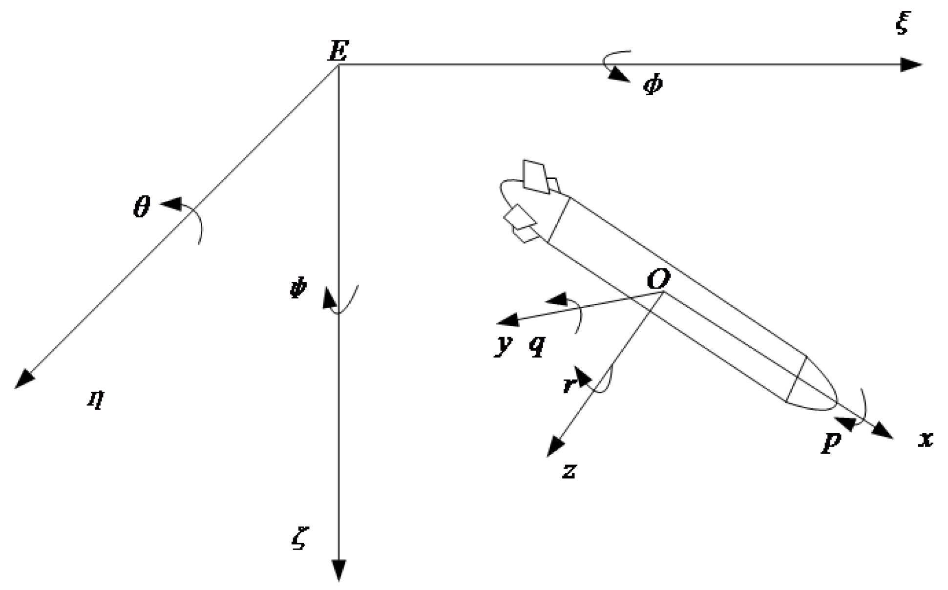
Figure 1. Coordinate system of AUV [2].
Electronics 08 00608 g001
Figure 2. The heading control system of AUV.
Electronics 08 00608 g002
Figure 3. Heading control system of MFAC.
Electronics 08 00608 g003
Figure 4. Heading control system of ADRC.
Electronics 08 00608 g004
Figure 5. Heading control system of MFAC based on ADRC.
Electronics 08 00608 g005
Figure 6. The desired heading tracked by TD.
Electronics 08 00608 g006
Figure 7. The interference estimated and compensated by ESO.
Electronics 08 00608 g007
Figure 8. Fuzzy control structure.
Electronics 08 00608 g008
Figure 9. Heading control of fuzzy optimized MFAC based on ADRC.
Electronics 08 00608 g009
Figure 10. Membership functions of e, e c .
Electronics 08 00608 g010
Figure 11. Membership functions of Δ a .
Electronics 08 00608 g011
Figure 12. Heading changes at different angles without interference.
Electronics 08 00608 g012
Figure 13. Heading control performance of four control methods without interference.
Electronics 08 00608 g013
Figure 14. Heading changes at different angles with interference.
Electronics 08 00608 g014
Figure 15. Heading control performance of four control methods with interference.
Electronics 08 00608 g015
Figure 16. Heading tracking curve of four control methods without interference.
Electronics 08 00608 g016
Figure 17. Heading tracking curve of four control methods with interference.
Electronics 08 00608 g017
Figure 18. Heading tracking curve of four control methods with interference.
Electronics 08 00608 g018
Figure 19. Photo of the Sailfish AUV.
Electronics 08 00608 g019
Figure 20. The experimental area.
Electronics 08 00608 g020
Figure 21. Heading change controlled by PID and MFAC.
Electronics 08 00608 g021
Figure 22. Heading change after stabilization.
Electronics 08 00608 g022
Figure 23. Heading change controlled by PID and MFAC.
Electronics 08 00608 g023
Figure 24. Heading change after stabilization.
Electronics 08 00608 g024
Figure 25. Heading change controlled by MFAC and MFAC based on ADRC.
Electronics 08 00608 g025
Figure 26. Heading change after stabilization.
Electronics 08 00608 g026
Figure 27. Heading change controlled by MFAC and MFAC based on ADRC.
Electronics 08 00608 g027
Figure 28. Heading change after stabilization.
Electronics 08 00608 g028
Figure 29. Heading change controlled by MFAC based on ADRC and fuzzy optimized MFAC based on ADRC.
Electronics 08 00608 g029
Figure 30. Heading change after stabilization.
Electronics 08 00608 g030
Figure 31. Heading change controlled by MFAC based on ADRC and fuzzy optimized MFAC based on ADRC.
Electronics 08 00608 g031
Figure 32. Heading change after stabilization.
Electronics 08 00608 g032
Figure 33. Heading change control performance of these four methods (40 degrees).
Electronics 08 00608 g033
Figure 34. Heading change control performance of these four methods (15 degrees).
Electronics 08 00608 g034
Figure 35. Path-tracking of right-angle linear tracking curve controlled by PID.
Electronics 08 00608 g035
Figure 36. Path-tracking of right-angle linear tracking curve controlled by fuzzy optimized MFAC based on ADRC.
Electronics 08 00608 g036
Figure 37. Heading tracking curve by PID.
Electronics 08 00608 g037
Figure 38. Heading tracking curve by fuzzy optimized MFAC based on ADRC.
Electronics 08 00608 g038
Table 1. Interval fuzzy rules of control architecture.
E/ECNBNMNSZPSPMPB
NBPBPBPMPMPSPSZ
NMPBPBPMPSPSZNS
NSPMPMPMPSZNSNS
ZPMPMPSZNSNMNM
PSPSPSZNSNSNMNM
PMPSZNSNMNMNMNB
PBZZNMNMNMNBNB
Table 2. Comparison of heading control performance of four control methods without interference.
MethodsOvershoot (°)Rising Time (s)Adjusting Time (s)Steady-State Error (°)
PID0.4613200
MFAC0.4410130
ADRC+MFAC012130
Fuzzy+ADRC+MFAC012130
Table 3. Comparison of heading control performance of four control methods with interference.
MethodsOvershoot (°)Rising Time (s)Adjusting Time (s)Steady-State Error (°)
PID3.99330
MFAC2.18150
ADRC+MFAC1.110150
Fuzzy+ADRC+MFAC011150
Table 4. Comparison of heading tracking performance of four control methods without interference.
MethodsRMS (°)RMSE (°)MAE (°)
PID6.23540.16020.1388
MFAC6.23260.13340.1137
ADRC+MFAC6.23070.11040.1003
Fuzzy+ADRC+MFAC6.22880.08910.0974
Table 5. Comparison of heading tracking performance of four control methods with interference.
MethodsRMS (°)RMSE (°)MAE (°)
PID6.23420.17990.1500
MFAC6.23030.12990.1086
ADRC+MFAC6.22940.11760.0978
Fuzzy+ADRC+MFAC6.22830.10090.0831
Table 6. Comparison of heading tracking performance of four control methods with interference.
MethodsRMS (°)RMSE (°)MAE (°)
PID6.23270.20230.1388
MFAC6.22970.15750.1137
ADRC+MFAC6.22880.14140.1003
Fuzzy+ADRC+MFAC6.22810.12970.0974
Table 7. Comparison of MFAC and PID with experimental data.
MethodsHeading Change (°)Overshoot (°)Rising Time (s)SSE (°)RMS (°)RMSE (°)
PID404.86132.2562.10850.2267
MFAC402.26161.3061.97580.1854
Table 8. Comparison of MFAC and PID with experimental data.
MethodsHeading Change (°)Overshoot (°)Rising Time (s)SSE (°)RMS (°)RMSE (°)
PID153.1671.6646.71141.7007
MFAC151.6290.5545.34480.3346
Table 9. Comparison of MFAC and MFAC based on ADRC with experimental data.
MethodsHeading Change (°)Overshoot (°)Rising Time (s)SSE (°)RMS (°)RMSE (°)
MFAC402.26161.3061.97580.1854
ADRC+MFAC401.81151.3061.31070.1285
Table 10. Comparison of MFAC and MFAC based on ADRC with experimental data.
MethodsHeading Change (°)Overshoot (°)Rising Time (s)SSE (°)RMS (°)RMSE (°)
MFAC151.6290.5545.34480.33467
ADRC+MFAC150.74100.3544.73290.2682
Table 11. Comparison of MFAC based on ADRC and fuzzy optimized MFAC based on ADRC with experimental data.
MethodsHeading Change (°)Overshoot (°)Rising Time (s)SSE (°)RMS (°)RMSE (°)
ADRC+MFAC401.81151.3061.31070.1285
Fuzzy+ADRC+MFAC400.5115060.12550.0292
Table 12. Comparison of MFAC based on ADRC and fuzzy optimized MFAC based on ADRC with experimental data.
MethodsHeading Change (°)Overshoot (°)Rising Time (s)SSE (°)RMS (°)RMSE (°)
ADRC+MFAC150.74100.3544.73290.2682
Fuzzy+ADRC+MFAC150.2311044.90640.0980
Table 13. Comparison of these four methods with experimental data.
MethodsHeading Change (°)Overshoot (°)Rising Time (s)SSE (°)RMS (°)RMSE (°)
PID404.86132.2562.10850.2267
MFAC402.26161.3061.97580.1854
ADRC+MFAC401.81151.3061.31070.1285
Fuzzy+ADRC+MFAC400.5115060.12550.0292
Table 14. Comparison of these four methods with experimental data.
MethodsHeading Change (°)Overshoot (°)Rising Time (s)SSE (°)RMS (°)RMSE (°)
PID153.1671.6646.71141.7007
MFAC151.6290.5545.34480.3346
ADRC+MFAC150.74100.3544.73290.2682
Fuzzy+ADRC+MFAC150.2311044.90640.0980
Table 15. Comparison of heading tracking performance of two control methods.
MethodsRMS Error (°)RMSE (°)MAE (°)
PID2.9755.79624.8083
Fuzzy+ADRC+MFAC1.81395.68684.3539