Article

Enforcing Optimal ACL Policies Using K-Partite Graph in Hybrid SDN

1
Department of Computer Science, Comsats University Islamabad, Wah Campus, Wah Cantt 47040, Pakistan
2
Department of Computer Science, University of Engineering and Technology, Taxila 47050, Pakistan
*
Author to whom correspondence should be addressed.
Electronics 2019, 8(6), 604; https://doi.org/10.3390/electronics8060604
Submission received: 1 April 2019 / Revised: 6 May 2019 / Accepted: 20 May 2019 / Published: 29 May 2019
(This article belongs to the Section Networks)

Abstract

:
Software Defined Networking (SDN) as an innovative network paradigm that separates the management and control planes from the data plane of forwarding devices by implementing both the management and control planes at a logically centralized entity, called controller. Therefore, it ensures simple network management and control. However, due to several reasons (e.g., deployment cost, fear of downtime) organizations are very reluctant to adopt SDN in practice. Therefore, a viable solution is to replace the legacy devices by SDN devices incrementally. This results in a new network architecture called hybrid SDN. In hybrid SDN, both SDN and legacy devices operate in such a way to achieve the maximum benefit of SDN. The legacy devices are running a traditional protocol and SDN devices are operating using Open-flow protocols. Network policies play an essential role to secure the entire network from several types of attacks like unauthorized access and port/protocol control. In a hybrid SDN, policy implementation is a tedious task that requires extreme care and attention due to the hybrid nature of network traffic. Network policies may be implemented at various positions in hybrid SDN, e.g., near the destination or source node, and at the egress or ingress ports of a router. Each of these schemes has some trade-offs. For example, if policies are implemented near the source nodes then each packet generated from the source must pass through the filter and, thus, requires more processing power, time, resources, etc. Similarly, if policies are installed near the destination nodes, then a lot of unwanted traffic generated causing network congestion. This is an NP-hard problem. To address these challenges, we propose a systematic design approach to implement network policies optimally by using decision tree and K-partite graph. By traversing all the policies, we built up the decision tree that identifies which source nodes can communicate with which destination. Then, we traverse the decision tree and constructs K-partite graph to find possible places (interfaces of the routers) where ACL policies are to be implemented based on the different criteria (i.e., the minimum number of ACL rules and the minimum number of transmissions for unwanted traffic). The edge weight represents the cost per criteria. Then, we traverse the K-partite graph to find the optimal place for ACL rules implementation according to the given criteria. The simulation results indicate that the proposed technique outperforms existing approaches in terms of computation time, traffic optimization and successful packet delivery, etc. The results also indicate that the proposed method improves network performance and efficiency by decreasing network congestion and providing ease of policy implementation.

1. Introduction

In a traditional computer network, both control and data planes are vertically implemented at each forwarding device, thus, a traditional computer network is distributed in nature. To control a traditional computer network, the operators usually implement fine-grained network policies known as Access Control Lists (ACL) at the network interfaces of switches/routers [1,2] by using low-level commands. The operators manually plane, design, and then implement these ACL policies according to network requirements. The present approach for implementing ACL is very complicated and error-prone [3,4,5]. A misconfiguration can drastically degrade the network performance by enabling unauthorized users to access confidential resources [6]. Moreover, it is also a costly process requiring a team of 10–30 members to handle a network of a hundred switches [7].
More recently, Software Defined Networking (SDN) has emerged as a new network architecture which decouples control plane from data plane by implementing a control plane at a logically centralized controller [8]. This induces that SDN has a centralized architecture. In SDN, the network operator can easily control packet forwarding by implementing ACL policies at the controller [9,10,11]. In this way, specific applications can be used to configure switches automatically for packet forwarding and policy implementation that eliminates the path misconfigurations [12] and other security attacks [13]. By using an OpenFlow protocol, network operators can implement action like forward, drop and modification of packet header [14], etc., as well as flow entries on the switches to drop the malicious packets based upon the network policy.
Nowadays, SDN is not widely adopted by organizations in practice except for some big companies like Google [15,16], Microsoft [17], VMware [18].
The main reason is the large budget that is required to establish a new network infrastructure from scratch [19], and another reason is fear of downtime when new infrastructure is being installed [20]. To accommodate these problems, an alternate solution is to deploy a limited number of OpenFlow switches alongside the legacy switches [21]. The remaining legacy switches can gradually be replaced with OpenFlow switches and finally realizing entire SDN deployment. A network having both types of network devices (i.e., OpenFlow switches and legacy switches) is known as a hybrid SDN [19,22]. In addition to the above, the following advantages can be achieved by using hybrid SDN:
  • As already discussed, the SDN establishment is costly. A large amount is needed to buy new SDN devices. Even after the establishment of pure SDN, network operators, administrators, and staff need the training to develop, configure and operate the SDN which also requires a large budget [23]. Hybrid SDN can easily relax these budgets.
  • By using Hybrid SDN, some benefits of the SDN model can adhere to [24]. For example, in an Internet Service Provider (ISP), there are millions of forwarding entries while OpenFlow network switches can support tens of thousands of forwarding entries [24]. In an ISP distribution network, OpenFlow devices can be used while the ISP access network can use legacy network devices as shown in Figure 1. In this way, ISP can observe a hybrid SDN in which OpenFlow switches are deployed in the distributed network to obtain the benefits of pure SDN while millions of forwarding entries are handled in the access network by using the legacy devices.
  • SDN provides fine-grained control for data traffic flows. If we require fine-grained control for a small portion of the network, then hybrid SDN can be deployed by using SDN devices in a small portion of the network [24]. For example, if a company, having network infrastructure shown in Figure 2, needs fine-grained control for the small part of the network in as indicated using the blue box, then only that portion will be upgraded to an SDN.
  • In case of in-band connection between SDN switches and the SDN controller and connectivity among SDN controllers, traditional routing protocols are very useful. Thus, by using a hybrid SDN, an SDN controller can be released from these tasks that can be handled by traditional protocols effectively.
  • The SDN infrastructure has recently appeared. OpenFlow switches are not as mature as traditional switches. So, network administrators vacillate to replace traditional network device with SDN devices at once. Hybrid SDN can comfort the transition from traditional network devices to SDN devices. For instance, Google [16] has deployed SDN in several steps over several years for management and control of their data centers.
  • In some scenarios, two SDNs are interconnected by traditional network switches. For these scenarios, hybrid SDN is required to allocate resources for the SDN interconnection suitably.
Network policies, like Access Control List (ACL), control the network behavior and are used by the operators to specify the network requirements [25,26]. The approach for implementation of ACL policies is different in SDN and traditional networsk as follows. In a traditional computer network, the operators usually implement ACL at the interfaces of switches/routers [1,2] by using low-level commands. The operators manually plan, design, and then implement these ACL policies according to network requirements. Thus, this approach for implementing ACL is very complicated and error-prone [3,4,5]. A misconfiguration can drastically degrade the network performance by enabling unauthorized users to access confidential resources [6]. Moreover, it is also a very expensive process requiring a team of 10–30 members to handle a network of hundred switches [7].
In SDN, ACL policies are specified at the controller, and thus, it is easy to do. Due to the different architecture of hybrid SDN from both SDN and traditional network, hybrid SDN needs new approaches to implement ACL policies. Recently, we have proposed a tree-based approach to implement the ACL policies at legacy network devices through an SDN controller in case of a topology change in hybrid SDNs, the detail of this approach is given in “Related Work”. However, in this approach, a tree is computed and traversed for each policy. It causes high processing overhead and large memory for a network having a large number of policies.
In this paper, we propose a single tree construction and traversal for all policies by reducing the processing overhead and reducing memory storage. Moreover, ACL policies may be implemented at the interfaces of legacy network devices in many ways, e.g., near the source nodes, near the destination nodes, at the egress ports and at the ingress ports [27], etc. All these ways for policy implementation have some tradeoffs as follows. If policies are implemented near source nodes, then they require filtration of each packet generated by source nodes. This method incurs extra processing overheads at the switches are attached directly to the source nodes for the packets that do not contradict with the policy. Similarly, if policies are implemented near destination nodes, then we require a large number of implementations according to destination nodes. Furthermore, any change in policy requires much effort and struggle from network operators. It will be explained through examples in the “Problem Statement”. Therefore, besides using single tree construction and traversal for all policies, we also embed the policies in the tree that the overall network performance is improved by reducing the processing and transmission overheads in the network and avoiding the ACL policies violation.
The rest of the paper is organized as follows. Section 3 presents the problem statement. The detail of the Proposed Solution is explained in Section 4. In Section 5 Simulation results are presented and Section 6 concludes the paper.

2. Related Work

In this section, we provide literature related to ACL policy implementation in traditional network, SDN and hybrid SDN.

2.1. ACL Implementation in Traditional Network

This section provides a thorough overview of the work related to the policy implementation mechanism in traditional networks. Zhang et al. [28] discuss the implementation of multiple packet filters like firewall, load balancer, etc., on the network devices to achieve required control and security of the network. HyperCuts decision trees [29] are used to handle the individual packet filter, but these are not efficient as a lot of memory is required to store them. In this approach, shared HyperCuts decision trees are introduced that are used to manipulate multiple packet filters as shown in Figure 3. To use shared HyperCuts decision trees, firstly, different packet filters are sorted that share some common features. Secondly, a machine learning mechanism is used to check which packet filters can be used in a shred form. For these shared packet filters, shared HyperCuts decision trees are classified based on a greedy algorithm. Experiment results indicate that shared HyperCuts decision trees consume less memory. However, the authors do not consider policy traversing optimization.
Diplomat [30] deliberates the problem of increasing number of ACL for network security and control. It is quite difficult to manage this large number of ACLs. To reduce the number of ACLs, compression is applied to these ACLs. In this mechanism, higher dimensional target patterns are transformed into lower dimensional patterns gradually. These patterns are firstly divided into a series of hyperplanes, then two adjacent hyperplanes are joined by resolving their differences. The differences are resolved by adding rules where they differ from each other. After this, two planes are merged into a single plane and this process is repeated for all planes. In the end, a single plane is formed, and Diplomat then repeats this process for each pattern; finally, a one-dimensional pattern is obtained that is executed by an existing optimal algorithm.

2.2. ACL Implementation in SDN

This section provides a thorough overview of the work related to policy implementation mechanism in Software Defined Networks. Liu et al. [31] proposed a scalable two-layers mechanism for implementing ACL policies. In the first layer, data packets are divided into different classes and forwarded to switches according to ACL policies. A class denotes the packets with some common properties i.e., having the same Destination IP address or same source subnet. Secondly, network security policies for different classes are deployed on different switches. These two-layer switches are known as a classified switch, i.e., to classify traffic and filter switch, i.e., to implement policy. By using this technique, the total number of flow entries are reduced by using the specific class to install policy. The entire system can be scaled easily by adding more switches and assigning a proper traffic class. Simulation results indicate that this mechanism is effective for moderate traffic load and robust. The limitation of this approach is the classification of traffic because traffic behavior changes dynamically which requires more intelligent traffic classification. Moreover, this technique does not consider the policy deployment for hybrid SDN.
NetEgg [32] is a programmable framework that facilities the network operators to implement different network policies to manage the network. It provides flexible and efficient ways to deploy network policies using example behaviors. In this approach, different example policies are designed based on the network operator’s response implementing actual policies on the network devices as shown in Figure 4. An algorithm is used to automatically synthesize policy implementation from these examples of policies. NetEgg [32] observes the operator’s behavior for the creation of network policies using time-line and topology. This algorithm infers the states that are required to be maintained to exhibit the desired behavior as well as the rule to process network packets according to policies. Most of the examples are taken from the literature to stipulate different policies, and later, these are used to infer other policies. The model results indicate that implementation scenarios exhibit the example used for policies. However, the overhead for this implementation is a significant issue that needs to be lowered.
In [33], behavior of different distributed routing protocols in traditional networks, such as OSPF [34] and IS-IS [35], are studied. It is concluded that these are robust and scalable, however, they lack flexibility. By using a centralized control plane, SDN provides fine-grained routing control and management. The paper [33] proposes a technique, known as fibbing [36,37], which combines the advantages of SDN route control and traditional routing protocols. Fibbing offers central control of the distributed computation of forwarding paths while striving for both flexibility and scalability. Fibbing introduces fake nodes, fake links, and fake routes to achieve load balancing. Through this fibbing, the SDN controller can persuade the legacy routers into computing desired paths by presenting the routers with carefully crafted network topologies. Fibbing does not require the installation of low-level rules in the legacy forwarding devices. Instead, the legacy routers simply run the legacy routing protocols based on their link state knowledge (which includes the fake nodes and links). A limitation of this approach is the computational effort for finding the fake nodes and links. If the network topology changes, then the fake nodes and links need to be recalculated.

2.3. ACL Implementation in Hybrid SDN

Fayazbakhsh et al. [12] discussed that network traffic is modified by the dynamic and opaque behavior of legacy switches that violates the two main promises of SDN. (i) ORIGIONBINDING strong binding between packet and its “origin” means packet generator (ii) PATHFOLLOWPOLICY Explicit policies should determine the paths that packets follow. Network Address Translation (NAT) and load balancing applications modify the packet headers that violate the ORIGIONBINDING. For example, the response served from a proxy’s cache may violate PATHSFOLLOWPOLICY. To cope with this limitation, the SDN paradigm is extended to adopt FlowTags architecture [38]. FlowTags envisages simple extensions to middleboxes to add tags that are carried in packet headers. SDN switches use these tags to modify the flow entries for packet forwarding. FlowTags implementation requires two prerequisites: (i) adequate header bits with SDN switch support to match on tags, and (ii) extensions to middlebox software. These Flowtags enable ACL policy implementation and verification for middleboxes as well as SDN switches. The limitation of this approach is that Flowtags need to add an additional component in the middleboxes which is tedious work for vendor-specific devices.
Amin et al. [6] investigated the problems and issues that occurred upon policy implementation due to a change in topology of the network. These issues may include unauthorized access to data, restricting access network resources, etc. To handle these problems, an automatic Policy Violation Detection for Topology Change (auto-PDTC) policy configuration technique is proposed. The network topology gets updated due to the addition or exclusion of network links or devices in an enterprise network. These changing topologies severely affect the configurations of network policies that are implemented on switches or router interfaces. When topology changes, it is time to verify the effectiveness of network policies to adhere to the organization objectives. Auto-PDTC offers an automatic mechanism that detects the topology change and validates the policies for the respective interfaces. The change in network topology is computed using the graph difference method. In the case of topology change, affected interfaces are indicated where policies need to be re-configured. The limitations of this study [6] are that only a single ACL policy is considered by using tree traversing. If we have multiple policies, then for each policy, multiple trees need to be traversed. There is a need to adopt some mechanism to reduce the overhead imposed by these separate tree-traversing method.
It is clear from the above research that optimal policy implementation is not discussed properly in the literature. It is a big issue because the proper implementation of network policies requires much effort and determination. It affects the entire network performance as well as switches, routers and other networking devices efficiency [39]. The following are the research challenges that need to be addressed to implement policies optimally.
  • In case of hybrid SDN, legacy network devices need to be configured for ACL implementation. There is a need for a mechanism that can automatically enforce commands on legacy devices to configure policies.
  • If there is a large number of nodes to implement policies, then what are the the optimum ways for policy implementation?
  • If there are multiple policies, then these policies cannot be implemented in one go. It needs any mechanism to simplify these policies so that we can implement these in a single iteration.
  • Network Loops may occur when policies are implemented; how to deal with these network loops.
  • Due to complex policy implementation, some network nodes may not be reachable.
  • During policy implementation, load balancing should be considered, so that no network devices are overwhelmed.

3. Problem Formulation

There are many ways to implement policies in the entire network, i.e., near the source nodes or near the destination nodes, and at the ingress ports of devices or at the egress port of devices, etc. Each implementation has some trade-offs as follows.

3.1. Different Ways of ACL Policy Implementation

i
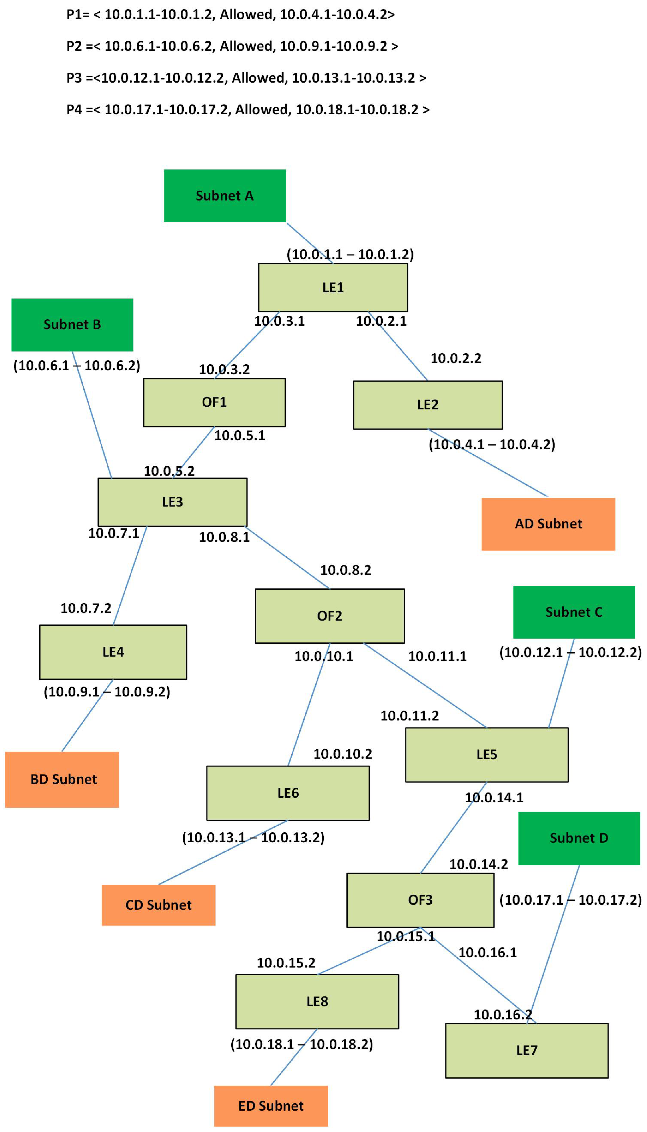
Near the source policy implementation: Near the source policy implementation is more efficient by blocking the unwanted traffic as generated by the source node; if the source nodes are distributed then this way of policy implementation requires a large number of ACL policies and, in turn, causes a longer packet process at switches.
Suppose that a company has an enterprise network shown in Figure 5. This network contains eight legacy switches LE1-LE-8, and three OpenFlow switches OF1-OF3. Users are connected to switches, i.e., LE1, LE3, LE5 and LE7, and data centers are connected to switches, i.e., LE2, LE4, LE6, and LE8 as shown in Figure 5. The company has the network policy, say P1, that the traffic generated by only subnet A1–A2 is allowed to reach the data center AD1–AD2. Near the source, policy implementation requires to implement Eight number of policies at the switches LE1, LE3, LE5 and LE7 that the traffic destined for AD1–AD2 should be blocked as shown in Figure 5. Now every packet generated by the nodes attached to the switches (LE1, LE3, LE5, LE7) will have to pass through these policies. Consequently, it causes a longer delay for the packets.
ii
Near the destination policy implementation: Continuing with the previous paragraph, we can implement P1 by using near to the destination policy implementation as follows. We implement at the egress interface of switch LE2 to allow the packets generated by A1–A2 and to drop all other packets as shown in Figure 5. This requires only two policies implemented at one switch. Thus, the packets generated by the nodes attached to the switches LE3 to LE7 will not have to pass through ACL policies and, subsequently, reducing the packet delay. However, in this case, unwanted traffic traverse through the entire network. That is, the traffic generated by D1 would traverse up to LE2 and then will be dropped here. This consumes more network resources like bandwidth, energy and processing power on the path from D1 to LE2 as shown is Figure 6 using a red dotted line.
iii
Egress port policy implementation: Similarly, we can implement policies at the egress ports of the switch LE2 where data centers AD1 and AD2 are attached. In the case, if destination nodes are less, e.g., 5–10 nodes, then it may be feasible to configure all the ports but if nodes are greater in number, e.g., more than 100 then it is challenging and sometimes impossible to configure all the ports for the desired policy. Similarly, any update in that policy is also quite cumbersome to configure.
iv
Ingress port policy implementation: we can implement policies at the ingress port of the switch LE2 where it is connected with LE1. In this case, we have to implement only two policies to block the traffic from all other subnets, i.e., B, C, and D, but in case of topology updates, this scheme may not be more feasible. So, optimum policy implementation is required that has less number of rules, on less number of interfaces, stop unwanted traffic as soon as possible, load balancing strategy for all routers, etc.

3.2. The Formal Technique to Deploy ACL Policies

In a traditional network, ACL policies are implemented manually. There is no formal algorithm/technique. For hybrid SDN, we have proposed a decision tree based mechanism to install ACL policies automatically. We had proposed to construct an individual decision tree for each policy (Amin et al. [6]). For example, we construct a decision tree to implement P1 as shown in Figure 7. By using this tree traversing policy, P1 is installed at the interface of LE2 and verifies that other data centers are not accessed by subnet A. Suppose that we have two other ACL policies, say P2 and P3. P2 describe that data centers BD1 and BD2 are only accessed by subnet B nodes, i.e., B1 and B2. This policy is implemented by using tree traversing explained in Figure 8. Similarly, policy P3 defines that subnet C nodes, (i.e., C1 and C2) are only allowed to access data centers CD1 and CD2. P3 is implemented using the tree traversing method explained in Figure 9. To implement all three policies, we need to construct and traverse three trees. If we have N number of policies, we will have to construct and traverse N number of trees. This is a more delicate and sluggish way.
We are concerned with the implementation of policies on network device interfaces. Related problems are the implementation of policy, change in policy (how easily we can make updates in previously implemented policies), adding new policies along with old policies.
We need to minimize the number of ACL policies and unwanted traffic which is a combinatorial problem. In a combinatorial problem, such subsets of network interfaces are searched where a minimum number of ACL policies are required, and unwanted traffic is also minimal. We propose in this paper to construct a decision tree and traverse by using K-partite graphs for all ACL policies. Moreover, we add the optimization parameter discussed in Section A in the tree.

4. Proposed Solution

To handle the problems discussed in Section 3, we proposed a systematic and efficient way for implementing multiple ACL policies in hybrid SDN by using a single decision tree with embedding optimization parameters (as discussed in Section 4.1). We model the hybrid SDN (HN) as ( H ) = ( V , L ) , where L is the set of undirected links and V represents the set of vertices, i.e., switches, routers. V consists of two types of switches, V = ( T O ) where T is set of traditional (legacy) switches, and O represents a set of OpenFlow switches. For this network, a path from a source node c to destination node d such that c d is presented as a set to traversed edges that is represented mathematically as p ( c , d ) = c , v 1 , v 2 , v k , d and where v 1 , v 2 v k ϵ { T O } . To minimize the number of policies and number of transmissions is a combinatorial problem, in which we must search such combinations of ports, where a minimum number of policies are required with a minimum number of transitions for unwanted traffic. Combinatorial problems involve finding a grouping, ordering, or assignment of a discrete, finite set of objects that satisfies given conditions. Candidate solutions are combinations of solution components that may be encountered during a solution attempt but need not satisfy all given conditions. Implementation of P policies on V vertices (switches) involves a set of combinations switch ports where policies are installed to secure the network. Furthermore, optimum policy implementation is also an NP-hard problem as there is no polynomial time algorithm to solve this problem. This problem is NP-hard like the most famous NP-hard problem (the decision subset sum problem) and the optimization problem of finding the least-cost cyclic route through all nodes of a weighted graph. We have to adopt the following strategies to implement policies optimally. Let c(v) represent the limit on the total number of ACL rules that can be configured on a switch v, including all its interfaces and in both traffic directions.
Minimum Rules Strategy: The operator wants to use a minimum number of rules on all switches in the network. Let V = V 1 , V 2 , V 3 , . V m represents the number of switches, P = P 1 , P 2 , P 3 , . . P n represent number of policies, R ( U i ) refers to number of rules on U switches to implement P i where UV, and U = U 1 , U 2 , U 3 , . U k .
M i n i = 1 n j = 1 m k = 1 l R ( ( P i ) ( V j ) )
Minimum Unwanted Traffic Strategy: Let Tr indicate the minimum unwanted traffic, it means that unwanted traffic should not go around the network. It should be dropped as early as possible. The operator wants to install rules on switches v in such way so that there is a minimum amount of unwanted traffic generated. Formally:
M i n T r ( v )
In Figure 10, we have shown the overall design of our system by showing the components and their interaction with the external environment. Efficient policy configuration systems consist of three main components. The first component is a decision tree construction showing the interconnection of network devices through links. The second component declares the policies that governed the data traffic. The third component considers the multiple policies configuration using decision tree traversing together with the K-partite graph.

4.1. Decision Tree Construction

We compute the topology of a network having both types of devices, i.e., OpenFlow and legacy at the SDN controller. An OpenFlow device exchanges its link state information with the SDN controller while the link state information of legacy devices is obtained by reading the configuration file of legacy devices remotely. This configuration file contains link state information as well as ACL policies information implemented on the network devices. Hence, after getting the link state information from both legacy and OpenFlow devices, i.e., switches and routers, we construct an undirected graph H by populating the set L with the links information and V with the nodes. More specifically, we use the Algorithm 1 for this purpose, which works as follows. Algorithm 1 shows that a link (also called edge) is selected from a set of links along with respective vertices and added to the graph H as shown in Figure 11. After this, another link along with respective vertices is selected and added to the graph H. This process continues until all links and edges are finished.
Algorithm 1 Decision Tree Construction
  1: Input: L is a set of links, V is a set of vertices
  2: Output: Graph H
  3: H= 0 // H is empty
  4: while the Instance is not solved do
  5:     Select the link from the L and vertices from V
  6:     if the edge connects two vertices in disjoint subsets then
  7:         merge the subsets;
  8:         add the edge to H;
  9:     end if
 10:     if All the subsets are merged then
 11:         the instance is solved
 12:     end if
 13: end while

4.2. Network Policy Representation

Through a 3-tuple <Source IP, Access Policy, Destination IP>, we represent a network-wide policy in our system. In this tuple, Source IP represents the policy for a packet originated from Source IP, Access Policy describes the specific actions (like drop (not allowed) or forward (allowed)) for the packet, and Destination IP represents the policy for the packet with destination address Destination IP. Source IP and Destination IP can be a particular IP address (like 10.1.1.1, a range 10.0.1.1-10.0.1.3, or wild card 10.0.1.*). Access Policy can be Allowed or Not Allowed. For example, a 3-tuple <10.0.1.1-10.0.1.2, Allowed, 10.0.4.1-10.0.4.2> means that packets originated from IP address 10.0.1.1-10.0.1.2 are only allowed to access devices with IP 10.0.4.1-10.0.4.2 and from any other subnet 10.0.4.1-10.0.4.2 cannot be accessed.
P 1 = < 10.0.1.1-10.0.1.2,Allowed,10.0.4.1-10.0.4.2 >
P 2 = < 10.0.6.1-10.0.6.2,Allowed,10.0.9.1-10.0.9.2 >
P 3 = < 10.0.12.1-10.0.12.2,Allowed,10.0.13.1-10.0.13.2 >
P 4 = < 10.0.17.1-10.0.17.2,Allowed,10.0.18.1-10.0.18.2 >

4.3. Decision Tree Traversing for Multiple ACL Policies

We have constructed a decision tree that represents the entire network topology i.e., switches, end hosts, routers, etc. We have four policies as discussed in Section 4.2. These policies are implemented at the network device’s interfaces according to the requirement. Some policies e.g., near the source, near the destination, implementation schemes are discussed in Problem Statement Section. One scheme has drawbacks or benefits over other schemes, therefore, none of them is perfect. In near the source policy implementation scheme, it requires a large number of ACL rules, and more processing power is required by the network devices to filter the network traffic. In near the destination policy implementation, the number of ACL rules are also proportional to the number of destination nodes, and it requires more bandwidth because packets are dropped after traveling the entire network at the destination nodes, e.g., more unwanted traffic is generated. We need to find such a mechanism which requires a minimum number of rules as well as minimum unwanted traffic. To implement policies optimally, we traverse the tree and find such ports by using K-partite graph traversing. We formed a K-partite Figure 12 for each policy. By computing the shortest path on K-partite graph optimal way of policy, a placement is found.
We traverse the decision tree by using a K-partite graph. In this K-partite graph shown in Figure 12, policies P1, P2, P3, etc., are at the leftmost side of the graph while on the other side partite is formed by using appropriate group number, e.g., G1, G2, G10, etc. The values on the edges of the links represent the number of rules required to implement ACL policy on the respective interface. The tree is traversed by using the Algorithm 2. In this Algorithm 2, firstly we move to the destination node in the tree according to given ACL policy then we start traversing the tree by exploring all the interfaces at each node. If we find source nodes then no rule is installed otherwise we install two for each interface. If there are multiple outgoing interfaces of the switches then rules are installed collectively on these interfaces.
Algorithm 2 Tree Traversing
  1: Input:
  2: P = P 1 , P 2 , P 3 , , P n is set of network policies
  3: DT is the decision tree constructed in Section 4.1
  4: G is a adjacency list that contains the groups numbers G i where i = 0, 1, 2, …, k against c t r t r a n s and c t r A C L values where c t r t r a n s and c t r A C L indicate the transmissions and rules count.
  5: We take a network policy, say Pi <Source IP, Access Policy, Destination IP>. For example, we take P1 = < 10.0.1.1-10.0.1.2, Allowed, 10.0.4.1-10.0.4.2>
  6: We take Destination IP of P i . In our example Destination IP of P 1 , it is 10.0.4.1-10.0.4.2.
  7: while Node in DT do
  8:     if node in destination list then
  9:         Find all similar nodes and create a group G i
 10:         Count number of c t r A C L and c t r t r a n s for G i
 11:          P i is connected to G i forming a K-partite graph
 12:         if Other Interfaces exist then
 13:            if Interface in Source IP list then
 14:                No rule installed
 15:            else
 16:                if Single Interface then
 17:                    Group G i is formed for this interface
 18:                    Count number of c t r A C L and c t r t r a n s for G i
 19:                     G i is added to K-Partite graph
 20:                end if
 21:                if Multiple Interfaces then
 22:                    Take all interfaces jointly, count two rules for each
 23:                    For each interface separate group G i is formed
 24:                    Count number of c t r A C L and c t r t r a n s for G i
 25:                    All G i is added to K-Partite graph in connecting each other in a series
 26:                end if
 27:            end if
 28:         end if
 29:     else
 30:         if Node is leaf then
 31:            Explore other similar nodes (leaves) connected to the switch
 32:            if Nodes Interfaces in Source IP list then
 33:                No rule installed
 34:            else
 35:                Create group G i of all similar leaves connected to the switch
 36:                Count number of c t r A C L and c t r t r a n s for G i
 37:                 G i is added to K-Partite graph
 38:            end if
 39:         end if
 40:         if Other Interfaces exist then
 41:            if Single Interface then
 42:                Group G i is formed for this interface
 43:                Count number of c t r A C L and c t r t r a n s for G i
 44:                 G i is added to K-Partite graph
 45:            end if
 46:            if Multiple Interfaces then
 47:                Take all interfaces jointly, count two rules for each
 48:                For each interface separate group G i is formed
 49:                Count number of c t r A C L and c t r t r a n s for G i
 50:                All G i is added to K-Partite graph in connecting each other in a series
 51:            end if
 52:         end if
 53:     end if
 54: end while
We can explore, the different policy implementation ways by traversing the decision tree. Suppose we have a policy P1 = < 10.0.1.1-10.0.1.2, Allowed, 10.0.4.1-10.0.4.2> in which first tuple i.e., 10.0.1.1-10.0.1.2 represents the Source IP and last tuple i.e., 10.0.4.1-10.0.4.2 represents the Destination IP address. According to this policy, only Source IP address, i.e., 10.0.1.1-10.0.1.2 is allowed to access respective Destination IP and all other subnets are not allowed to access this destination. To explore all interfaces for policy implementation, we traverse the decision tree DT by using this policy. Policy can be implemented at a single interface or at multiple interfaces to secure the Destination IP. We form the groups based on the set of interfaces where policies can be implemented. So, these groups are formed on the basis of rules implementation, e.g., a group can have a single interface or multiple interfaces according to the policy. For example, group G1 represent the Destination IP that contains two IP addresses, i.e., 10.0.4.1-10.0.4.2, group G2, G3 contains single IP address, i.e., 10.0.2.2., 10.0.2.1 respectively. We need to calculate the number of rules c t r A C L and number unwanted transmissions c t r t r a n s to implement the policy for these respective groups. G is an adjacency list that contains the group’s numbers against c t r t r a n s and c t r A C L values. In the end, this adjacency list forms a K-partite graph.
We traverse the decision tree to find the node linked with the interfaces having Destination IP, i.e., 10.0.4.1-10.0.4.2, node LE2 is the matching one. After finding the matching node, we find all the interfaces of LE2, i.e., (10.0.4.1, 10.0.4.2, and 10.0.2.2). For destination IP, i.e., 10.0.4.1-10.0.4.2 group G1 is formed, and two rules are implemented at each interface thus, c t r t r a n s , and c t r A C L values are counted for G1 as c t r A C L = 4 and c t r t r a n s = 74 as shown in Figure 13a. Actually, c t r t r a n s value is calculated from leaf nodes by using a recursive function. Hence we denote the final value. Now we have single interface 10.0.2.2 remaining, group G2 is formed, and two rules are implemented thus, c t r A C L = 2 and c t r t r a n s = 74 for this group as shown in Figure 13b. We move to next node LE1, and two rules are implemented at the connecting interface and group G3 is formed with values c t r A C L = 2 and c t r t r a n s = 62 as indicated in Figure 13c. There are three other interfaces, i.e., 10.0.1.1, 10.0.1.2, and 10.0.3.1, where interfaces 10.0.1.1 and 10.0.1.2 are connected with source IP, so no rule is implemented on these interfaces. Only single interface 10.0.3.1 is remaining, so two rules are installed, and group G4 is formed, and c t r A C L = 2 and c t r t r a n s = 62 for this group and an edge is added to K-partite graph as shown in Figure 13d. Similarly, other interfaces are processed, and groups G5, G6, and G7 are added to the K-partite graph shown in Figure 13d. Next we reach node LE2 that is connected to multiple interfaces, i.e., 10.0.6.1, 10.0.6.2, 10.0.7.1 and 10.0.8.1, where interfaces 10.0.6.1 and 10.0.6.2 are end nodes so a group G8 is formed and two rules are implemented at each interface thus, c t r t r a n s , and c t r A C L values are counted for G8 as c t r A C L = 4 and c t r t r a n s = 2 as shown is Figure 13e. For other interfaces i.e., 10.0.7.1 and 10.0.8.1 an individual group is formed for each interface i.e., G9 and G10 c t r A C L = 2 for each group while c t r t r a n s = 4 for G9 and c t r t r a n s = 32 for G10. It is noted that we have to install ACL policies collectively on all these groups so in K-partite graph these groups are added in series as shown in Figure 13e.
For multiple choices, we add edges in K-partite graph in parallel format, i.e., G9, G11, and G12. For the collective implementation of ACL policies edges are added in series form, i.e., G8, G9, G13. In this way, all the interfaces are processed, and finally, a complete K-partite graph emerges as shown in Figure 12.
In K-partite graph, each link has two values, i.e., c t r A C L and c t r t r a n s ; by adding these values a single link value is computed as shown in Figure 14. K-partite graph shows a lot of options to install network policies on different network devices. By calculating the shortest path for the K-partite graph using Algorithm 3, a set of options are indicated where policies can be installed. To find actual policy placement subset of groups, we assume that four transmissions are equal to one policy rule as policy implementation requires more computation power and resources than transmission. We have computed the link value by keeping a policy rule similar to four transmissions that are shown in Figure 15. From Figure 15, the shortest path is 64 for path G8, G11, G16, and G18. If ACL policies are deployed at these interfaces, one can observe limited unwanted traffic as well as a minimum number of ACL rules. Similarly, for other network policies, K-partite graphs are formed, and by applying the shortest path algorithm, a set of interfaces can be found where policies can be implemented optimally.
Algorithm 3 Shortest Path for K-Partite graph
  1: Set M = m, d(m) = 0
  2: for All neighbor nodes u to m, set d(u) = w(m,u) do
  3:     for All other non neighbor nodes, set d ( u ) = do
  4:         while M V do
  5:            Choose vertex v ϵ M with d ( v ) minimum
  6:            Set M = M ϵ v
  7:            for All neighbor nodes q to v such that q ϵ M do
  8:                if d(q) > d(v) + w(v,q) then
  9:                    Set d(q) = d(v) + w(q,v)
 10:                end if
 11:            end for
 12:         end while
 13:     end for
 14: end for
Optimum policy implementation is an NP-hard problem as there is no polynomial time algorithm to solve this problem. This problem is NP-hard similar to the most famous NP-hard problem which is the decision subset sum problem and the optimization problem of finding the least-cost cyclic route through all nodes of a weighted graph.
In Figure 16, interaction among different components of the proposed system is shown. In this system, we get the network topology information from switches and other network devices in the form of a topology graph. A 3-tuple network policy is traversed using a decision tree that governs a K-partite graph. After this step, the shortest path for K-partite graph is computed that indicates the switch ports were policies can be installed optimally, i.e., less number of rules with minimum unwanted traffic.

5. Simulation Results

To evaluate the performance of our proposed solution, we developed the complete architecture and algorithms in Mininet [40] and POX controller [41]. We used a random topology generator [42] to produce a different set of network scenarios. We performed these experiments on 64-bit Ubuntu Linux 16.01 LTS operating system that is installed on an HP ENVY Notebook with Intel Core Intel(R) Core(TM) i5-6200U CPU @ 2.30 GHz, 8 GB RAM and 500 GB SATA HDD. The network topology is created using both type of switches, i.e., legacy switches and OpenFlow switches. OpenFlow switches can be used as legacy switches by setting the ovs to fail mode as a “standalone,” and these are disconnected from the SDN controller. Some switches and policies are varied for different network topologies. All links are assumed to be bi-directional with a bandwidth of 100 Mbps for each direction. SDN nodes randomly initiate data requests with traffic demands uniformly selected from 512 kbps to 3 Mbps discretely with a step size of 128 kbps. To compute the time for graph traversing, a number of switches are varied as 5, 10, 15, 20, 25, 30, 35, 40, 45, and 50, Similarly, the number of policies also varied as 10, 20, 30, 40, 50, 60, 70, 80, 90, 100. We used the following parameters to evaluate the entire performance of the proposed approach:
  • Graph Computation Time: Graphs are traversed for a specific policy to find appropriate places (interfaces) for rule installation. Firstly, network policy is traversed on the decision tree, and the K-partite graph is created. Secondly, the shortest path is computed on a K-partite graph having a subset of the interface where policies can be installed.
  • Traffic Optimization: Policy implementation plays important role in traffic optimization. If policies are deployed at the proper places, then network congestion can be avoided and traffic losses are eliminated. By using a K-partite graph, we regularized the overall network traffic, so that the minimum number of rules are installed with the best route for network traffic.
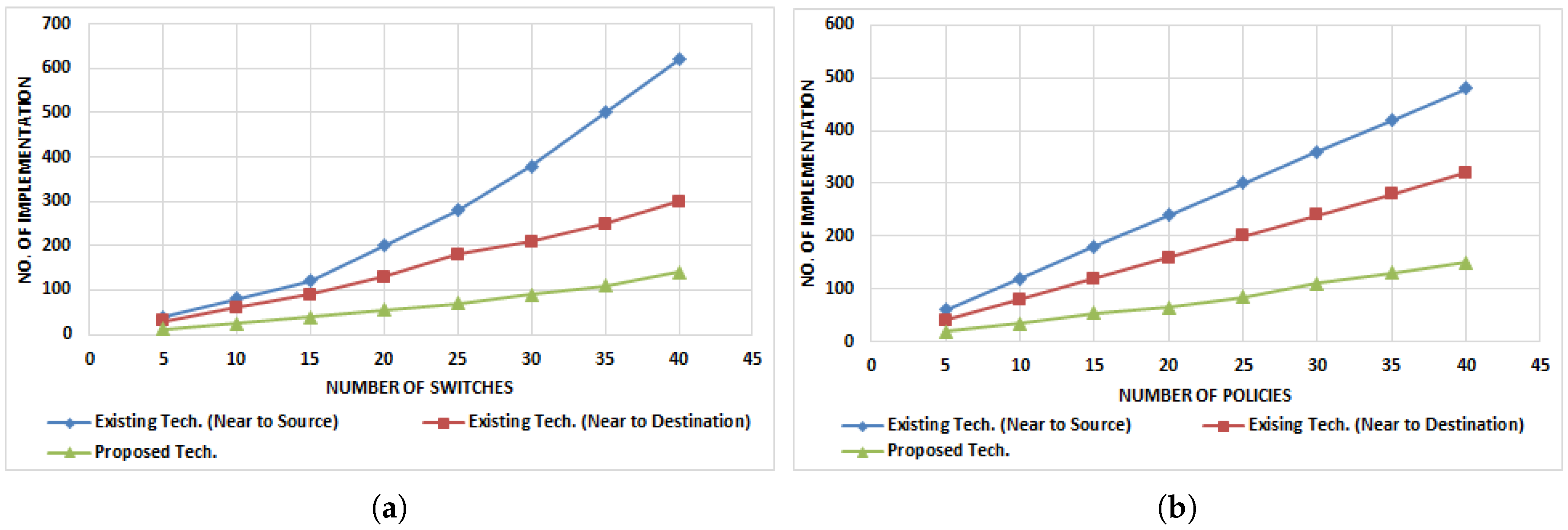
  • Number of ACL rule versus Number implementations: To secure the entire network, ACL rules are implemented on the network devices. If we install ACL rules at the egress ports of the switch where end nodes are connected, then the number of rules is directly proportional to the number of nodes. If ACL rules are installed at the ingress port of the switch, then a fewer number of rules are needed. When policies are implemented at proper places, then a fewer number of rules are required.
  • End-to-End Delay Computation: End-to-End delay defines the total time consumed for a data packet to be reached across a network from the source node to the destination node. End-to-End Delay = Number of switches + Transmission of N number of packets − (Transmission delay + Processing + Queuing).
  • Successful Packet Delivery (SPD) ratio: This implies the total number of packets received at destination nodes according to the specific policy to the total number of packets generated from the source nodes by considering different policy implementation schemes, i.e., near the source, near the destination, etc.
We assume that there are a different number of policies and switches that vary from time to time. The approach adopted in [6] is an existing approach. It is necessary for the network administrator to implement policies on new interfaces according to specification. For this purpose, firstly, the network administrator will translate the network policy to corresponding network rules. Secondly, this policy will be configured on switches using ACL commands. This task requires a lot of time to implement policies properly on respective interfaces. We considered three different schemes for policy implementation; the first is policy implementation near the source nodes, the second way is to implement policy near the destination nodes, and the third one is to find some optimum policy placements. We perform each experiment about 30 times by varying different parameters like number of nodes, number of switches and number of policies, etc. We evaluated network traffic for several network topology combinations and reported the trends among these patterns in the form of results. Network traffic varies form 1 Mbps to 10 Mbps on the demand of network users.

5.1. Graph Computation Time

In our proposed scheme, graph computation plays an important role. We need to use several graphs to find an optimization for ACL rules placement. We represent the network topology in the form of a graph that is transferred to a decision tree. After this step, we traverse this tree by using network topology for a specific policy to generate a K-partite graph. Then, the shortest path is computed for this K-partite graph to find a set of interfaces. In the existing technique, most of the work is done manually, while our approach performs all the operations of policy optimizing automatically.

5.1.1. Graph Computation Time by Varying Number of Switches

Figure 17 shows graph computation time for the existing and proposed techniques. In the existing technique, for each policy, a separate tree is traversed to install each policy in which allowed and not allowed options of policy tuple are traversed to restrict the network traffic according to ACL policy. In the proposed techniques, multiple policies are traversed using a single decision tree that saves the network operator’s time for policy design and placement as well as time for policy computation. We performed these experiments in two phases; in the first phase, we vary the number of switches from 1 to 10 with a difference of precisely one switch while in second phase number of switches are varied from 5 to 50 where the difference number of switches is 5.
The graph in Figure 17a shows the variation of switches according to the first phase. Results indicate that the computation time differs in small values, i.e., 0.1, 0.2, 0.3, etc. With the increase in the number of switches computation time increases. The graph in Figure 17b represents the execution time for 50 ACL policies and by varying number of switches in the network form 5 to 50. The graph curve indicates that in the proposed technique, less time is required to implement the same number of policies in hybrid SDN.

5.1.2. Graph Computation Time by Varying Number of Policies

In Figure 18, graph computation time by the varying number of policies is shown. In this graph, the number of policies varies from 10 to 100 while the number of switches is kept constant at size 20. As discussed in Section 5.1.1, due to separate tree traversing for each policy implementation, more time is required. When policies are varying, it means a large number of policies are being installed, so more time is required as indicated in the graph. The resulting graph shows that execution time for the proposed technique and existing technique is fairly less. We present the results using two different graphs; the first graph represents the results when policies are varying with a single value, i.e., 1, 2, 3, and so on. The second graph represents the computation time when policies vary by 10 units i.e., 10, 20, 30, etc.
Figure 18a indicates the effects of varying number of policies while the number of switches is constant. In this graph, variation in policies is very small, so maximum computation time is 3.5 s for the existing approach while for the proposed approach it is about 1.3 s. Results indicate 40% increase in computation time when the number of policies are going to increase. In Figure 18b a big change in computation time can be observed. We change the number of policies with a difference value of 10. So, the resulting graph shows a 50–60 percent increase in the time for graph computation.

5.2. Traffic Optimization

ACL policies implementation strategies play an important role in traffic optimization. If we efficiently implement policy, then we can eliminate not only unnecessary traffic but also CPU processing can be minimized. For example, if policies are implemented near source nodes, then it requires more processing power because each packet generated from the source node must pass through the filter. Similarly, if policies are implemented near designation nodes, then packets have to travel through the network and drop after reaching unauthorized destination nodes. In the second case, more unwanted traffic is generated. We need to minimize unwanted traffic.

5.2.1. Traffic Optimization by Varying Number of Policies

In Figure 19, unwanted traffic generated in the existing approach and proposed approach is compared. Network traffic can be optimized by using different policy schemes, i.e., near the source policy implementation scheme, near the destination policy scheme and optimized policy placement. We keep the number of switches constant at 25, the number of nodes is 50 and we change the number of policies as 10, 20, 30, 40, 50 and 60. For these three schemes, the ratio of unwanted traffic is measured for a different number of policies. Figure 19b shows that near the destination policy implementation scheme, we generate more unwanted traffic than other schemes. Because packets traverse from source to reach the destination node and then these packets are dropped. Near the source ACL policy implementation scheme generates less unwanted traffic but requires more processing power and more delay is observed in this case. Optimum policy implementation scheme decreases unwanted traffic and minimizes processing power.

5.2.2. Traffic Optimization by Varying Number of Switches

In Figure 20a,b, traffic optimizations for different policy schemes, i.e., near the source policy implementation, near the destination policy implementation and optimum policy placement are compared by varying the number of switches. We keep the number of policies constant at 20, and number of nodes is 40 and changes the number of switches as 5, 10, 15, 20, 25, 30, 35, and 40 as shown in Figure 20b. When there is less number of switches, then unwanted traffic ratio is less, and it is increased when the number of switches are increased. In Figure 20b, we varied the number of switches with a difference of 2 switches. The graph shows the variation of unwanted traffic for all three schemes. In our proposed scheme, less unwanted traffic is generated.

5.3. Number of ACL Implementations against ACL Policies

ACL policies are implemented on the ports of network devices; however, some ACL policies implementation varies for different schemes. If near the destination scheme or near the source scheme is adopted, then a large number of policies are implemented at the ports of network devices. Figure 21b shows the variation in the number ACL implementations concerning the number of policies. The figure shows that the optimal policy implementation scheme requires fewer policy implementation. Policy implementation increases with an increase in the number of policies. Figure 21a shows the policy implementations with a different number of switches while the number of policies is constant, i.e., 20. The figure represents the variation in the policy implementations when the number of switches is changed. In the case of near the source ACL policy implementation, a large number of policy implementations are required.

5.4. End-to-End Delay Computation

End-to-End delay computation is the key element to evaluate the improvement in the proposed system. If policies are implanted near the source or near the destination, then packets must traverse the longer path to reach the destination or to be discarded. In the proposed approach, ACL policies are implemented at the optimal places in the network, so unnecessary packets travelling is limited. In this way, the overall efficiency of the system is improved.

5.4.1. When Number of Switches Are Varying

When policies are applied near the source node then it requires a lot of effort to filter the traffic for a specific flow. So, End-to-End delay is very high for the existing approach. Figure 22a shows that the existing approach has a high delay when policies are implemented near source nodes or near the destination nodes. Our proposed approach indicates a relatively small end to end delay because it automatically implements policies on the optimal places in the network.

5.4.2. When Number of Policies Are Varying

Figure 22b represents the condition when policies are varying while the number of switches is constant. In this case, when the number of policies is increasing in number, then end-to-end delay increases. A small number of polices are implemented at a small number of interfaces so the chances of congestion are very low. Surely, this decreases the time delay for each individual packet to reach the destination node.

5.5. Successful Packet Delivery

We study how the different schemes of policy implementation affect the performance of the network. In this section, we present different performance comparison with a varying number of policies. We can observe from the results shown in the following sections that when the number of policies is increased, the successful packet delivery ratio decreases. It is because when the number of policies is increased then policies implemented on the switches require more effort and time to filter traffic according to a specific policy.

5.5.1. When Policies Are Placed near the Source

The following Figure 23a shows the successful packet delivery ratio when policies are implemented near source nodes. In this scheme of policy implementation, we can get less successful delivery of packets because filters need to process each packet from the source node. So this decreases the overall successful packets delivery. Form the Figure; it is clear that with an increase in the number of policies, the successful packet delivery decrease.

5.5.2. When Policies Are Placed near the Destination

Figure 23b indicates that when policies are implemented near destination nodes then successful packet delivery ratio increases as compared to near-source policy implementation. It happens because less processing is required by the switches to filter the traffic. The graph shows that with the increase of number policies successful packet delivery ratio decreases because a large number of policies require more processing and filtration.

5.5.3. When Policies Are Placed Optimally

We have proposed optimal policy implementation that increases the successful packets delivery. Figure 23c shows enhanced successful packet delivery as compared to the other two approaches. Figure 23c shows that with the increase in the number of policies successful packet delivery ratio is decreased. The existing mechanism has a meager SPD ratio.

6. Conclusions

In this paper, we proposed a novel approach to optimize the implementation of ACL policies in a hybrid SDN. We modeled the network policies using a 3-tuple, and by traversing all the policies, a decision tree is built that indicates the possible communication among source and destination nodes. Then, we traversed the decision tree using the 3-tuple network policy and constructed a K-partite graph to search for the possible placement of ACL policies. Edge weights on the K-partite graph represented the sum of the number of rules and number of transmissions for unwanted traffic. By computing the shortest path for K-partite graph, we got the set of points (i.e., interfaces of routers) where both values (i.e., number of ACL rules and number of transmissions for unwanted traffic) are minimum. This set of points is considered for ACL policy implementation. Simulation results show that our proposed technique outperforms the existing technique in terms of computation time, traffic optimization, SPD, delay, etc. In the future, we would like to use more sophisticated network policies implementation in hybrid SDN.

Author Contributions

Conceptualization, N.S. and R.A.; methodology, R.A.; software, R.A., W.M.; validation, R.A. and N.S.; formal analysis, N.S.; writing—original draft preparation, R.A.; writing—review and editing, W.M., N.S.; visualization, R.A.; supervision, N.S.; project administration, N.S.; funding acquisition, W.M., R.A.

Funding

This research received no external funding.

Conflicts of Interest

The authors declare no conflict of interest.

References

  1. Nguyen, X.N.; Saucez, D.; Barakat, C.; Turletti, T. Rules placement problem in openflow networks: A survey. IEEE Commun. Surv. Tutor. 2016, 18, 1273–1286. [Google Scholar] [CrossRef]
  2. Masood, R.; Shibli, M.A.; Ghazi, Y.; Kanwal, A.; Ali, A. Cloud authorization: Exploring techniques and approach towards effective access control framework. Front. Comput. Sci. 2015, 9, 297–321. [Google Scholar] [CrossRef]
  3. Wang, K.; Qi, Y.; Yang, B.; Xue, Y.; Li, J. LiveSec: Towards effective security management in large-scale production networks. In Proceedings of the 2012 32nd International Conference on IEEE Distributed Computing Systems Workshops (ICDCSW), Macau, China, 18–21 June 2012; pp. 451–460. [Google Scholar]
  4. Ali, M.; Khan, S.U.; Vasilakos, A.V. Security in cloud computing: Opportunities and challenges. Inf. Sci. 2015, 305, 357–383. [Google Scholar] [CrossRef]
  5. Wei, L.; Zhu, H.; Cao, Z.; Dong, X.; Jia, W.; Chen, Y.; Vasilakos, A.V. Security and privacy for storage and computation in cloud computing. Inf. Sci. 2014, 258, 371–386. [Google Scholar] [CrossRef]
  6. Amin, R.; Shah, N.; Shah, B.; Alfandi, O. Auto-Configuration of ACL Policy in Case of Topology Change in Hybrid SDN. IEEE Access 2016, 4, 9437–9450. [Google Scholar] [CrossRef] [Green Version]
  7. Sherry, J.; Hasan, S.; Scott, C.; Krishnamurthy, A.; Ratnasamy, S.; Sekar, V. Making middleboxes someone else’s problem: Network processing as a cloud service. ACM SIGCOMM Comput. Commun. Rev. 2012, 42, 13–24. [Google Scholar] [CrossRef]
  8. Sezer, S.; Scott-Hayward, S.; Chouhan, P.K.; Fraser, B.; Lake, D.; Finnegan, J.; Viljoen, N.; Miller, M.; Rao, N. Are we ready for SDN? Implementation challenges for software-defined networks. IEEE Commun. Mag. 2013, 51, 36–43. [Google Scholar] [CrossRef] [Green Version]
  9. Yoon, C.; Park, T.; Lee, S.; Kang, H.; Shin, S.; Zhang, Z. Enabling security functions with SDN: A feasibility study. Comput. Netw. 2015, 85, 19–35. [Google Scholar] [CrossRef]
  10. Ding, A.Y.; Crowcroft, J.; Tarkoma, S.; Flinck, H. Software defined networking for security enhancement in wireless mobile networks. Comput. Netw. 2014, 66, 94–101. [Google Scholar] [CrossRef]
  11. Kim, H.; Feamster, N. Improving network management with software defined networking. IEEE Commun. Mag. 2013, 51, 114–119. [Google Scholar] [CrossRef]
  12. Fayazbakhsh, S.K.; Chiang, L.; Sekar, V.; Yu, M.; Mogul, J.C. Enforcing Network-Wide Policies in the Presence of Dynamic Middlebox Actions using FlowTags. In Proceedings of the 11th USENIX Conference on Networked Systems Design and Implementation, Seattle, WA, USA, 2–4 April 2014; Volume 14, pp. 533–546. [Google Scholar]
  13. Haque, M.R.; Tan, S.C.; Yusoff, Z.; Lee, C.K.; Kaspin, R. DDoS Attack Monitoring using Smart Controller Placement in Software Defined Networking Architecture. In Computational Science and Technology; Springer: Singapore, 2019; pp. 195–203. [Google Scholar]
  14. Specification, O.S. OpenFlow Switch Specification: Version 1.5.1 [Online]. Available online: https://www.opennetworking.org/wp-content/uploads/2014/10/openflow-switch-v1.5.1.pdf (accessed on 30 December 2018).
  15. Hoelzle, U. Openflow@ google. Open Netw. Summit 2012, 17, 136. [Google Scholar]
  16. Jain, S.; Kumar, A.; Mandal, S.; Ong, J.; Poutievski, L.; Singh, A.; Venkata, S.; Wanderer, J.; Zhou, J.; Zhu, M.; et al. B4: Experience with a globally-deployed software defined WAN. In ACM SIGCOMM Computer Communication Review; ACM: New York, NY, USA, 2013; Volume 43, pp. 3–14. [Google Scholar]
  17. Hong, C.Y.; Kandula, S.; Mahajan, R.; Zhang, M.; Gill, V.; Nanduri, M.; Wattenhofer, R. Achieving high utilization with software-driven WAN. In ACM SIGCOMM Computer Communication Review; ACM: New York, NY, USA, 2013; Volume 43, pp. 15–26. [Google Scholar]
  18. Maltz, D.A.; Greenberg, A.G.; Patel, P.K.; Sengupta, S.; Lahiri, P. Data Center Interconnect and Traffic Engineering. U.S. Patent 8,160,063, 17 April 2012. [Google Scholar]
  19. Levin, D.; Canini, M.; Schmid, S.; Schaffert, F.; Feldmann, A. Panopticon: Reaping the Benefits of Incremental SDN Deployment in Enterprise Networks. In Proceedings of the USENIX Annual Technical Conference, Philadelphia, PA, USA, 19–20 June 2014; pp. 333–345. [Google Scholar]
  20. Amin, R.; Reisslein, M.; Shah, N. Hybrid SDN Networks: A Survey of Existing Approaches. IEEE Commun. Surv. Tutor. 2018, 20, 3259–3306. [Google Scholar] [CrossRef]
  21. Markovitch, M.; Schmid, S. Shear: A highly available and flexible network architecture marrying distributed and logically centralized control planes. In Proceedings of the 2015 IEEE 23rd International Conference on Network Protocols (ICNP), San Francisco, CA, USA, 10–13 November 2015; pp. 78–89. [Google Scholar]
  22. Canini, M.; Feldmann, A.; Levin, D.; Schaffert, F.; Schmid, S. Panopticon: Incremental Deployment of Software-Defined Networking. In Proceedings of the ACM Symposium on SDN Research, Santa Clara, CA, USA, 14–15 March 2016. [Google Scholar]
  23. Vissicchio, S.; Vanbever, L.; Bonaventure, O. Opportunities and research challenges of hybrid software defined networks. ACM SIGCOMM Comput. Commun. Rev. 2014, 44, 70–75. [Google Scholar] [CrossRef]
  24. Vissicchio, S.; Vanbever, L.; Cittadini, L.; Xie, G.G.; Bonaventure, O. Safe Update of Hybrid SDN Networks. IEEE/ACM Trans. Netw. 2017, 25, 1649–1662. [Google Scholar] [CrossRef]
  25. Ahmad, I.; Kumar, T.; Liyanage, M.; Okwuibe, J.; Ylianttila, M.; Gurtov, A. Overview of 5G security challenges and solutions. IEEE Commun. Stand. Mag. 2018, 2, 36–43. [Google Scholar] [CrossRef]
  26. Kellerer, W.; Kalmbach, P.; Blenk, A.; Basta, A.; Reisslein, M.; Schmid, S. Adaptable and Data-Driven Softwarized Networks: Review, Opportunities, and Challenges. Proc. IEEE 2019, 107, 711–731. [Google Scholar] [CrossRef]
  27. Lain, A.; Goldsack, P. Distributed Network Connection Policy Management. U.S. Patent 9,178,850, 3 November 2015. [Google Scholar]
  28. Zhang, B.; Ng, T.S.E. On Constructing Efficient Shared Decision Trees for Multiple Packet Filters. In Proceedings of the 2010 IEEE INFOCOM, San Diego, CA, USA, 14–19 March 2010. [Google Scholar]
  29. Singh, S.; Baboescu, F.; Varghese, G.; Wang, J. Packet classification using multidimensional cutting. In Proceedings of the 2003 Conference on Applications, Technologies, Architectures, and Protocols for Computer Communications, Karlsruhe, Germany, 25–29 August 2003; pp. 213–224. [Google Scholar]
  30. Daly, J.; Liu, A.X.; Torng, E. A difference resolution approach to compressing access control lists. IEEE/ACM Trans. Netw. 2016, 24, 610–623. [Google Scholar] [CrossRef]
  31. Liu, J.; Li, Y.; Wang, H.; Jin, D.; Su, L.; Zeng, L.; Vasilakos, T. Leveraging software-defined networking for security policy enforcement. Inf. Sci. 2016, 327, 288–299. [Google Scholar] [CrossRef]
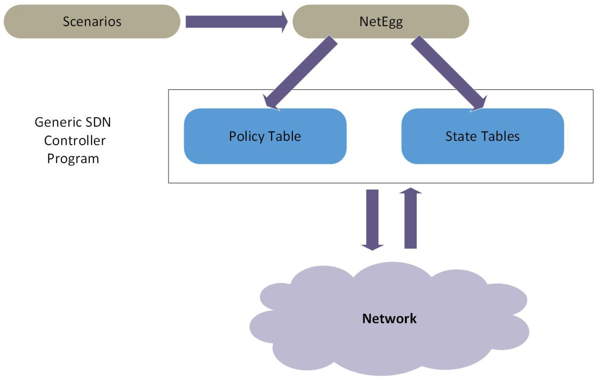
  32. Yuan, Y.; Alur, R.; Loo, B.T. NetEgg: Programming Network Policies by Examples. In Proceedings of the 13th ACM Workshop on Hot Topics in Networks—HotNets-XIII, Los Angeles, CA, USA, 27–28 October 2014; pp. 1–7. [Google Scholar] [CrossRef]
  33. Vissicchio, S.; Vanbever, L.; Rexford, J. Sweet little lies: Fake topologies for flexible routing. In Proceedings of the 13th ACM Workshop on Hot Topics in Networks—HotNets-XIII, Los Angeles, CA, USA, 27–28 October 2014; pp. 1–7. [Google Scholar]
  34. Kim, D. A framework for hierarchical clustering of a link-state internet routing domain. In International Conference on Information Networking; Springer: Berlin/Heidelberg, Germany, 2003; pp. 839–848. [Google Scholar]
  35. Smit, H.; Li, T. Intermediate System to Intermediate System (IS-IS) Extensions for Traffic Engineering (TE). 2004. Available online: https://tools.ietf.org/html/rfc3784 (accessed on 28 May 2019). RFC 3784, RFC Editor.
  36. Vissicchio, S.; Tilmans, O.; Vanbever, L.; Rexford, J. Central control over distributed routing. ACM SIGCOMM Comput. Commun. Rev. 2015, 45, 43–56. [Google Scholar] [CrossRef]
  37. Tilmans, O.; Vissicchio, S.; Vanbever, L.; Rexford, J. Fibbing in action: On-demand load-balancing for better video delivery. In Proceedings of the 2016 ACM SIGCOMM Conference, Florianopolis, Brazil, 22–26 August 2016; pp. 619–620. [Google Scholar]
  38. Fayazbakhsh, S.K.; Sekar, V.; Yu, M.; Mogul, J.C. Flowtags: Enforcing network-wide policies in the presence of dynamic middlebox actions. In Proceedings of the Second ACM SIGCOMM Workshop on Hot Topics in Software Defined Networking, Hong Kong, China, 16 August 2013; pp. 19–24. [Google Scholar]
  39. Sharma, P.K.; Rathore, S.; Jeong, Y.S.; Park, J.H. SoftEdgeNet: SDN Based Energy-Efficient Distributed Network Architecture for Edge Computing. IEEE Commun. Mag. 2018, 56, 104–111. [Google Scholar] [CrossRef]
  40. Team, M. An Instant Virtual Network on Your Laptop (or Other PC). [Online]. Available online: http://mininet.org/ (accessed on 28 May 2019).
  41. Kaur, S.; Singh, J.; Ghumman, N.S. Network programmability using POX controller. In Proceedings of the ICCCS International Conference on Communication, Computing & Systems, Gurgaon, India, 9–11 September 2014; Volume 138. [Google Scholar]
  42. Jin, C.; Chen, Q.; Jamin, S. Inet: Internet Topology Generator. Available online: http://topology.eecs.umich.edu/inet/ (accessed on 28 May 2019).
Figure 1. An Example of hybrid SDN scenario: OpenFlow switches are deployed in the distribution network to obtain the benefits of SDN while millions of forwarding entries are handled in the access network by using legacy devices.
Electronics 08 00604 g001
Figure 2. Example of hybrid SDN in an enterprise network: The network portion in the blue box needs fine-grained control and is upgraded to SDN, while the rest of the network continues to operate with legacy switches.
Electronics 08 00604 g002
Figure 3. Example of Shared HyperCuts tree: (Left) Two separate HyperCuts trees. (Right) The corresponding shared HyperCuts tree.
Electronics 08 00604 g003
Figure 4. NetEgg Design layout using Generic SDN Controller.
Electronics 08 00604 g004
Figure 5. An example Scenario containing SDN and Legacy switches connected with end Nodes.
Electronics 08 00604 g005
Figure 6. An example Scanrio containing SDN and Legacy switches connected with end Nodes.
Electronics 08 00604 g006
Figure 7. Graph traversing for policy P1.
Electronics 08 00604 g007
Figure 8. Graph traversing for policy P2.
Electronics 08 00604 g008
Figure 9. Graph traversing for policy P3.
Electronics 08 00604 g009
Figure 10. Entire System Model.
Electronics 08 00604 g010
Figure 11. Decision Tree for Multiple Policies.
Electronics 08 00604 g011
Figure 12. K-partite Graph that shows the different combinations of switch port to install ACL policies. Shortest path for entire K-partite graph is calculated that gives the optimal policy implementation points.
Electronics 08 00604 g012
Figure 13. Step by step formation of K-partite graph. (a) A group G1 is formed that is attached with node P1 forming a K-partite graph; (b) A group G2 is formed that is attached with node P1 forming a K-partite graph; (c) A group G3 is formed that is attached with node P1 forming a K-partite graph; (d) Multiple groups G4–G7 are added to graph forming a K-partite graph; (e) Groups G8, G9 and G10 are added in the K-partite graph as a series of edges for collective ACL implementations.
Electronics 08 00604 g013
Figure 14. K-partite Graph in which link values are combined as a discrete value.
Electronics 08 00604 g014
Figure 15. K-partite Graph with scaled values of number of rules and number of transmissions. Shortest path for this K-partite graph is calculated that gives the optimal policy implementation points.
Electronics 08 00604 g015
Figure 16. Flow Chart for proposed solution.
Electronics 08 00604 g016
Figure 17. Simulation results of proposed and existing approaches for Graph Computation Time. (a) Computation Time when the Number of switches is varying and the number of policies is constant; (b) Computation Time when Number of switches is varying and number of policies is constant.
Electronics 08 00604 g017
Figure 18. Simulation results of proposed and existing approaches for Graph Computation Time. (a) Computation Time when Number of policies is varying, and the number of switches is constant; (b) Computation Time when Number of policies is varying and number of switches is constant.
Electronics 08 00604 g018
Figure 19. Simulation results of proposed and existing approaches for Traffic Optimization. (a) Traffic Optimization when the Number of policies is varying, and the number of switches is constant; (b) Traffic Optimization when the Number of policies is varying and number of switches is constant.
Electronics 08 00604 g019
Figure 20. Simulation results of proposed and existing approaches for Traffic Optimization. (a) Traffic Optimization when Number of switches is varying, and the number of policies is constant; (b) Traffic Optimization when Number of switches is varying and number of policies is constant.
Electronics 08 00604 g020
Figure 21. Simulation results of proposed and existing approaches for No. of ACL Implementations. (a) Number of ACL implementations against a number of ACL policies when the number of switches is varying; (b) Number of ACL implementations against number of ACL policies when number of policies is varying.
Electronics 08 00604 g021
Figure 22. SPD for near the Destination policy Implementation Scheme. (a) End-to-End Delay Computation when number of switch is varying and number of polices is constant; (b) End-to-End Delay Computation when the number of policies is varying and number of switches is constant.
Electronics 08 00604 g022
Figure 23. SPD for near the Destination policy Implementation Scheme. (a) SPD for near the Source policy Implementation Scheme; (b) SPD for near the Destination policy Implementation Scheme; (c) SPD for Optimal policy Implementation Scheme.
Electronics 08 00604 g023

