Article

Efficient and Compact Near-Field Coupled Hybrid Antenna Using a Single Radiating Subwavelength Split-Ring Resonator

Department of Electrical and Computer Engineering and Research Center OPTIMAS, Technische Universität Kaiserslautern, 67663 Kaiserslautern, Germany
*
Author to whom correspondence should be addressed.
Electronics 2019, 8(5), 527; https://doi.org/10.3390/electronics8050527
Submission received: 19 March 2019 / Revised: 2 May 2019 / Accepted: 7 May 2019 / Published: 11 May 2019
(This article belongs to the Section Microwave and Wireless Communications)

Abstract

:
Modern applications in the realms of wireless communication and mobile broadband Internet increase the demand for compact antennas with well defined directivity. Here, we present an approach for the design and implementation of hybrid antennas consisting of a classic feeding antenna that is near-field-coupled to a subwavelength resonator. In such a combined structure, the composite antenna always radiates at the resonance frequency of the subwavelength oscillator as well as at the resonance frequency of the feeding antenna. While the classic antenna serves as impedance-matched feeding element, the subwavelength resonator induces an additional resonance to the composite antenna. In general, these near-field coupled structures are known for decades and are lately published as near-field resonant parasitic antennas. We describe an antenna design consisting of a high-frequency electric dipole antenna at f d = 25 GHz that couples to a low-frequency subwavelength split-ring resonator, which emits electromagnetic waves at f SRR = 10.41 GHz. The radiating part of the antenna has a size of approximately 3.2 mm × 8 mm × 1 mm and thus is electrically small at this frequency with a product k · a = 0.5 . The input return loss of the antenna was moderate at 18 dB and it radiated at a spectral bandwidth of 120 MHz. The measured main lobe of the antenna was observed at 60 with a 3 dB angular width of 65 in the E-plane and at 130 with a 3 dB angular width of 145 in the H-plane.

1. Introduction

Antennas play a key role in modern industrial communication technology as for example in wireless networked systems, dedicated point-to-point communication links and mobile broadband internet. Connectivity has become an important factor in the industry, where data transfer between machines is essential for the organization of processes in manufacturing lines. Also in the private sector, communication applications spread from the Internet of Things, as e.g., home automation, to small consumer electronics as used in smart wearables. In all these devices and systems, stringent requirements are imposed on the maximal size of the used antennas or antenna arrays. As an ultimate goal, antennas are desired to be electrically small for integration. Furthermore, the radiation of such antennas must be directive in order to increase their efficiency and hence to reduce power consumption in battery-powered systems.
In this context, metamaterial inspired antenna designs have gained large interest in recent years [1,2,3,4,5,6,7,8,9]. Electrically small antennas (ESAs) moved into the focus of ongoing research [10,11,12,13,14,15], especially those exploiting split-ring resonators (SRRs) [12,16,17,18,19,20,21,22].
Here, we present an approach for the design of hybrid antennas that relies on the electromagnetic near-field-coupling between a classic antenna and a single subwavelength resonator. In such a combined structure, the classic antenna assumes the role of an impedance-matched feeding antenna that resonantly transfers its energy radiationless to the subwavelength resonator. The subwavelength resonator subsequently emits electromagnetic waves at its own resonance frequency. Since both elements couple in the near-field, the combined antenna occupies only a small volume in space. Interestingly, a properly designed hybrid antenna always radiates at the resonance frequency of the subwavelength resonator, independent of the resonance frequency of the feeding antenna. This basically allows us to combine a subwavelength oscillator, that is inherently significantly smaller than the wavelength of the emitted wave, with a high-frequency feeding antenna, that is also smaller than the emitted wavelength of the combined structure. This implies that the approach is very well suited for the design and implementation of electrically small antennas according to the Chu-Wheeler criterion [23] k · a < 1 with the wave number k and radius a of the smallest possible sphere around the antenna.
In this report, we propose a near-field resonant parasitic antenna design, which consists of a single subwavelength split-ring resonator (SRR) that is fed via electric and magnetic near-field coupling by an electric dipole antenna. The SRR resonantly emits radiation at its resonance frequency of f SRR = 10.41 GHz while the electric dipole has a design frequency of f d 25 GHz. Unlike previously reported antenna designs, which partially consist of sophisticated 3-D or multi-layer structures [12,13,16,17,18,19,20,21], our composite antenna is built from a simple planar stack of just two circuit boards and thus can be manufactured by standard processes. Furthermore, our approach only involves a single subwavelength element as radiator, which enables us to efficiently implement electrically small antennas with a directed radiation pattern.

2. Dipole Antenna with Split Ring Resonator

As described above, the presented antenna is a hybrid combination of a classic antenna and a subwavelength resonator. While the classic antenna itself has the typical electromagnetic size of about half a wavelength and is therefore designed to efficiently radiate waves at its antenna resonance frequency, its radiative properties dramatically change when the electric and magnetic field are near-field-coupled to a subwavelength resonator with differing resonance frequency. The hybrid structure of a classic antenna and a subwavelength oscillator can be excited with low insertion loss at the resonance frequency of the subwavelength element, although the classic antenna alone would not be excitable at this frequency. The subwavelength oscillator assumes the role of the radiating element and transmits electromagnetic waves at its own resonance frequency. This is confirmed by the observation that the hybrid structure always radiates at the resonance frequency of the subwavelength resonator, independent of the resonance frequency of the antenna. Interestingly, the hybrid structure is also efficient for large differences between the resonance frequencies of the classic antenna and subwavelength radiator, since the properties of the hybrid antenna are largely governed by the electric and magnetic near-field-coupling between classic antenna and subwavelength resonator.
In this context, we investigated the electromagnetic properties of the near-field-coupling between a dipole antenna and a subwavelength SRR. In this specific design, the resonance frequency of the dipole antenna at f d 25 GHz was significantly larger than the resonance frequency of the SRR at f SRR = 10.41 GHz. In the combined structure, the dipole antenna serves as the feeding element and resonantly transfers energy to the bianisotropic SRR via both electric and magnetic near-field-coupling. After excitation, the SRR radiates electromagnetic waves into free space at its own resonance frequency. Our analysis of the surface currents also evidences that the SRR is the radiating element in the composite structure.
To investigate the spatial and spectral properties of the near-field-coupling between dipole antenna and SRR, we first numerically calculated the electromagnetic fields and the surface currents in the hybrid device. In order to obtain reliable simulation results, we exactly implemented the geometry of the hybrid antenna as fabricated for the experimental investigation, including the SMA connector and the feed line. For the full wave 3-D simulations we used CST Microwave Studio® 2018.
The geometric dimensions of the coupled dipole antenna and SRR structure are shown in Figure 1. The hybrid structure is composed of three vertically stacked metal layers, where the SRR is located in the middle layer, the left dipole arm of the anthenna in the top layer and the right dipole arm in the bottom layer. This is schematically illustrated in Figure 1a, where we left out the substrates and the SMA connector fot the sake of clarity. A more detailed description of the layers is shown in Figure 1b,d. Starting from the top layer, the left dipole arm is placed on the top side of a RT/duroid® 5880 substrate with the outer dimensions indicated in Figure 1b. Below the duroid substrate, a second duroid substrate with itentical outer dimensions is placed, which contains the SRR on its top side serving as the middle layer, see Figure 1c, and the right arm of the dipole antenna on its bottom side as the bottom layer, see Figure 1d. The gap of the SRR is exactly aligned with the gap of the antipodal dipole to ensure maximal capacitive coupling between dipole antenna and SRR. The upper layer also contains the lightly tapered stripline to the left dipole arm, whereas the lower layer hosts the strongly tapered ground stripline to the right dipole arm. The detailed physical dimensions of the dipole arms and SRR are illustrated in Figure 1e,f, respectively. Figure 1g,h depict the bottom and the top side of the hybrid antenna including the SMA connector that was also taken into account in the numerical calculations. For the determination of the electric size of the radiating element of the hybrid antenna, which consists of the dipole and the SRR, we calculated the product between the magnitude of the wave vector k of the radiated wave and the radius a of the smallest possible sphere around the radiating part of the hybrid antenna. With a smallest sphere radius of a = 2.3 mm, we obtained k · a = 0.5 at a resonance frequency of f SRR = 10.41 GHz. Therefore, we concluded that the radiating part of our hybrid antenna is electrically small, in compliance with the Chu-Wheeler criterion k · a < 1 .
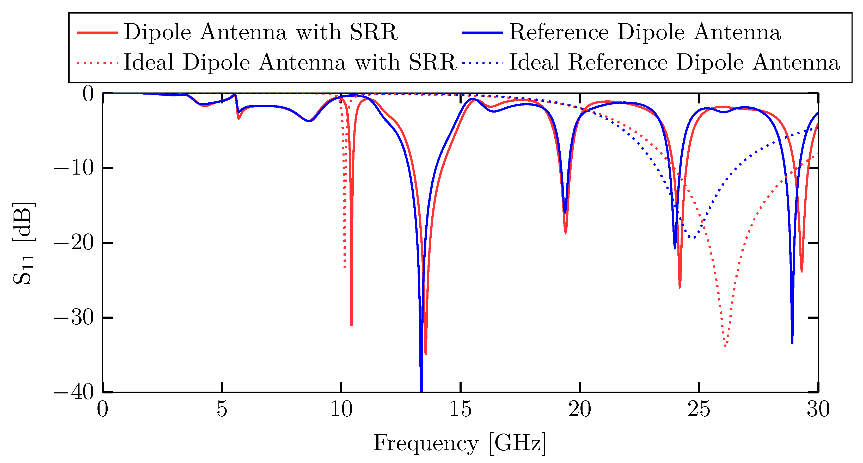
To study the coupling from a microwave source to the hybrid antenna, we numerically calculated the dependence of the S 11 -amplitude on the microwave frequency. For reference, we also determined the S 11 -amplitude of the dipole antenna without the SRR. In all cases, the numerical calculation accounted for the feed lines and the SMA connector. The spectral dependence of the S 11 -amplitudes of the hybrid antenna and the dipole antenna without SRR are shown in Figure 2 as blue and red solid line, respectively. For assessing the efficiency of the coupling from the microwave source to the antenna via the SMA connector and the feed lines, we also calculated S 11 -amplitudes of idealized versions of the hybrid antenna and the electric dipole antenna without SRR, when they were directly excited by a discrete port in the gap of the dipole antenna. In the idealized case, the SMA connector and the feed lines were not considered in the simulation model. The corresponding S 11 -amplitudes are plotted in Figure 2 as blue and red dotted lines. The hybrid antenna exhibits several resonant spectral dips in the S 11 -amplitude, whose origins can be most readily identified by comparison with the idealized hybrid antenna without connector and feed line. A comparison shows that the spectral dip at f SRR = 10.41 GHz displays the resonant oscillation of the SRR. The resonant dip at 24 GHz stems from the electric dipole antenna. This can be explained by comparison between the S 11 -amplitude of the hybrid antenna without SMA connector and feed line, and the S 11 -amplitude of the idealized dipole antenna without SRR, whose working frequency was designed for f d = 25 GHz. From the S 11 -amplitude of the idealized hybrid antenna we can conclude that the resonance frequency of the dipole antenna increases to 26 GHz, when the SRR is added. This blue-shift is caused by capacitive and inductive coupling to the SRR. However, the resonance frequency decreases from 26 GHz to 24 GHz again, when the feed line and SMA connector are appended, which is obvious by comparison of the S 11 -amplitudes. The sharp dips at 13.5 GHz, 19.5 GHz and 29.3 GHz originate exclusively from the feed line and connector, yet do not impact the resonant behavior of the hybrid antenna at the working frequency of f SRR = 10.41 GHz. The S 11 -amplitude of the hybrid antenna at the working frequency was 30 dB, which assures sufficient excitation.
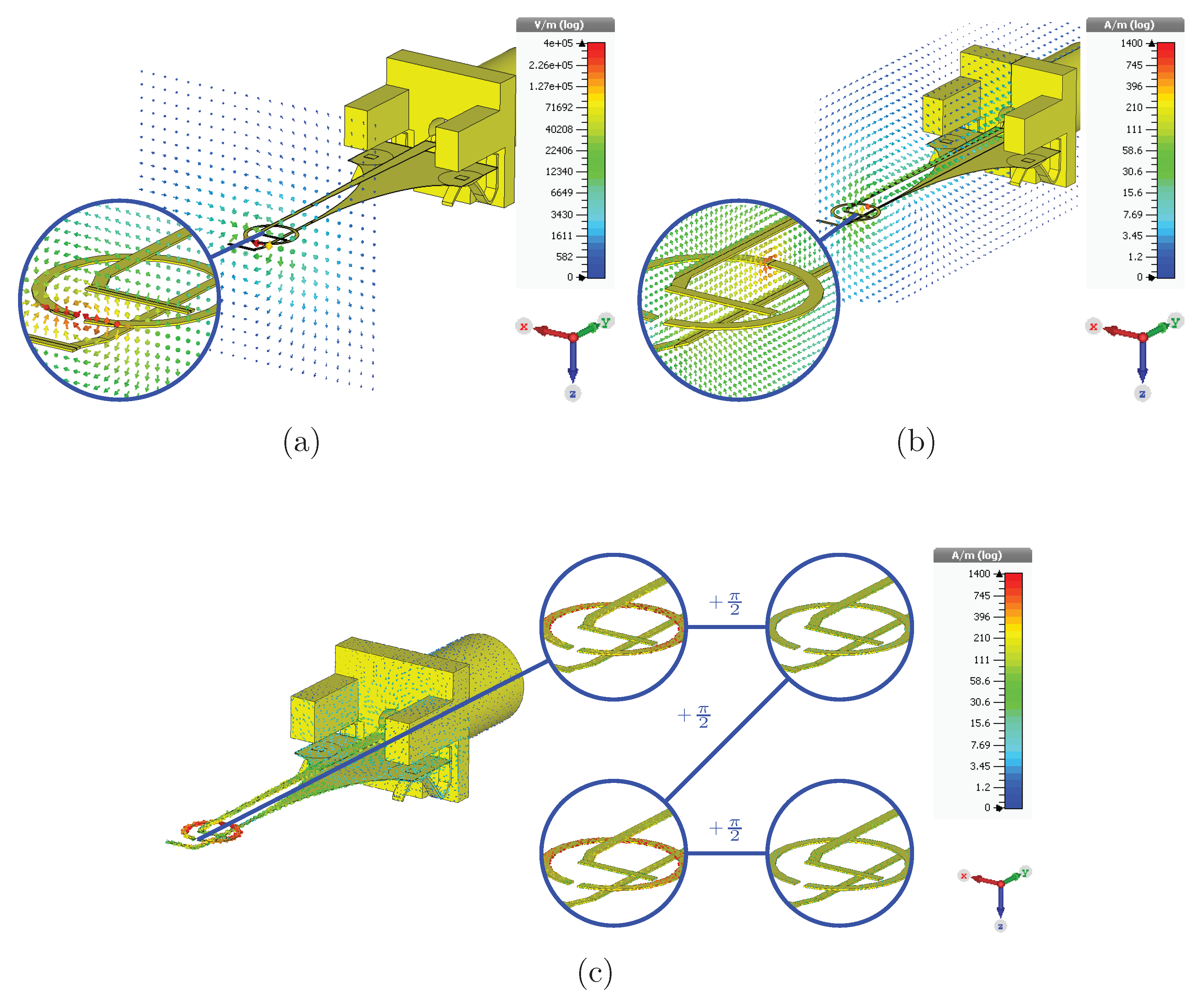
In a next step, we investigated the electromagnetic near-field-coupling between the dipole antenna and the SRR. We observed that both electric and magnetic field coupling occurs between the two components and that the combined coupling explicitly determines the electromagnetic behavior of the hybrid device. In fact, its electromagnetic properties change completely, if one of the coupling mechanisms is missing. To study the electric coupling, we numerically calculated the spatial distribution of the electric field strength, which is plotted along the x-z cutting plane in Figure 3a. For clarity, we did not depict the dielectric substrates in the electric field plots. Electric near-field-coupling occurs by capacitive coupling of the electric fields between the gap of the dipole antenna and the gap of the SRR. The electric field of the dipole antenna resonantly excites closed loop currents in the SRR by displacing the charges in the ring. The excited surface currents of the dipole antenna, and more specifically of the SRR, are illustrated in Figure 3c. The zoomed insets show the surface currents on the SRR for advancing phase at steps of π / 2 . As can be seen, the surface currents build closed loops on the SRR and are significantly stronger on the SRR than on the dipole antenna. The oscillation strength of the SRR surface currents is maximal at the resonance frequency of f SRR = 10.41 GHz, where most of the electromagnetic energy is transferred from the dipole antenna to the SRR. The magnetic field coupling is shown in Figure 3b. The magnetic field penetrates the SRR and induces closed loop surface currents that are resonant at the same frequency as the surface currents excited by the electric coupling. We also elicited if either electric or magnetic coupling only would imply the same electromagnetic behavior of the hybrid antenna as observed for combined coupling. For pure magnetic coupling, we eliminated electric coupling by turning the split ring by 90 around the z-axis, such that the electric field of the dipole antenna could no longer couple to the capacitive gap of the SRR. As a result, almost no energy was transferred from the dipole antenna to the SRR. Reversely, to limit the near-field-coupling to purely electric coupling, we turned the ring by 90 around the y-axis, such that the magnetic field did not penetrate the SRR. Again, almost no energy was transferred from the dipole antenna to the SRR, which lets us conclude that the combined coupling is crucial to efficiently excite the SRR. Furthermore, it is notable that the S 11 -amplitudes of Figure 2 indicate low reflection of the fed microwave at the hybrid antenna, which is a sign for strong resonant coupling exactly at the resonance frequency of the SRR at f SRR = 10.41 GHz. As a result, most of the excitation energy is accepted by the antenna, which is also evidenced by the high magnitude of the surface currents in the SRR. To rule out high absorption in the metal and the dielectric of the antenna, we also numerically calculated the occurring losses as well as the radiation efficiency. Due to the resonant nature of the SRR, the calculated loss in the antenna amounts to 12%, while the overall calculated efficiency of 87.9 % is considerably high for an electrically small antenna. For this reason, we can expect that a fabricated hybrid antenna also radiates efficiently into free space.
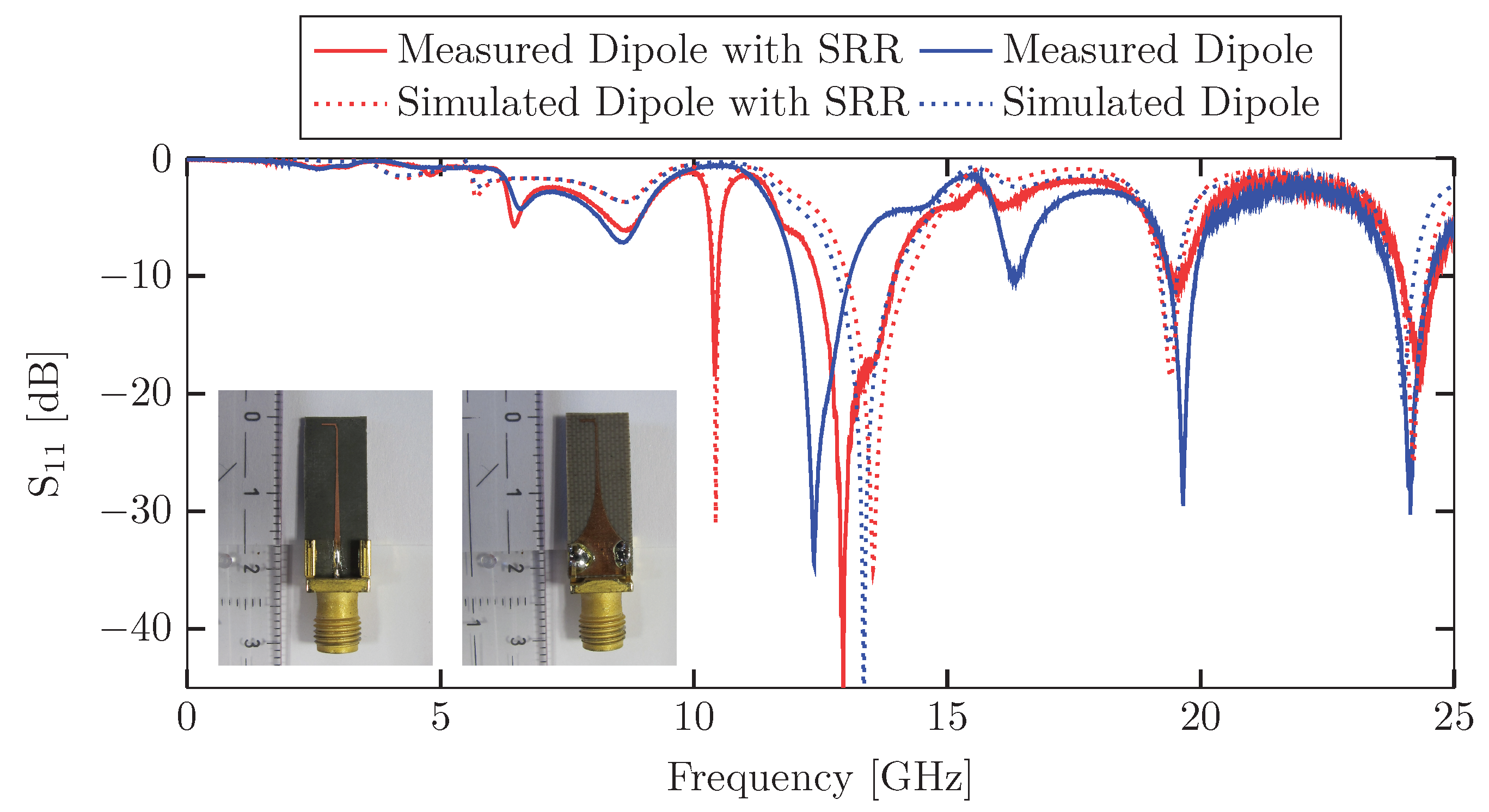
For examination of the applicability of our findings, we fabricated both the electrically small hybrid antenna consisting of the dipole antenna and the SRR as well as a reference antenna composed of the same dipole antenna without SRR. We investigated both the coupling of a microwave source to the hybrid antenna, i.e., the S 11 -amplitude, and the electric far-field spatial pattern of the electric field of the antenna. Furthermore, we compared these quantities to the corresponding numerical results.
Figure 4 shows the simulated and measured S 11 -amplitudes of the hybrid dipole antenna with SRR. For reference, we also simulated and measured the S 11 -amplitudes of a dipole antenna with the same physical dimensions as for the hybrid antenna, yet without SRR. The insets depict the hybrid dipole antenna with SRR from the front and back side.
The S 11 -amplitude of the hybrid antenna displays several distinct spectral minima. First, we recognize a reflection minimum with an input return loss of 18.1 dB at f SRR = 10.41 GHz, which corresponds to the resonance frequency of the SRR. We measured a 10 dB coupling bandwidth of 120 MHz at this frequency, which exactly matches the simulated value. Second, we identified a spectral minimum at f dipole = 24.2 GHz, which occurs exactly at the resonance frequency of the dipole antenna. Finally, we state that all other spectral minima between 12 GHz and 21 GHz stem from the stripline and the SMA connector, however do not impact the performance of the hybrid antenna at the working frequency of f SRR = 10.41 GHz.
To study the radiative properties, we numerically calculated and experimentally measured the spatial angular distribution of the electric far field of the hybrid antenna, which is shown in Figure 5 at the resonance frequency f SRR = 10.41 GHz. It should be noted that we could only measure the electric far-field of the antenna in forward direction, which corresponds to the right hemisphere in the polar diagrams and angles between 0 and 180 in both the E-plane and the H-plane. This restriction was imposed by our specific experimental set-up and is not a limitation of the antenna itself. As it can be seen in Figure 5b, we also measured the electric field in the H-plane for angles between 180 and 195 by rotating the antenna under test by 15 around the normal to the H-plane. By this means, we were able to record a second set of electric far-field data in the agular range between 15 and 195 . Figure 5a displays the electric far-field distribution in the E-plane, while Figure 5b depicts the distribution in the H-plane. The relative orientation of the hybrid antenna to the defined planes is illustrated in the insets of the polar diagrams. In order to compare the numerically calculated E-field amplitudes with the measured quantities, we normalized the amplitudes to 0 dB. The radial lines in the diagrams mark the 3 dB angular width of the main lobe of the radiation pattern. We observed the main lobe direction of the antenna at 60 with a 3 dB angular width of 65 in the E-plane, in good agreement with the numerical calculations. In the H-plane, the main lobe is directed at 130 with a 3 dB angular width of 145 , also in good agreement with the numerical values. The reason for the deviation of the main lobe direction from the 90 axis in the E-plane and H-plane is caused by the asymmetry of the feed line. This argument is corroborated by a comparison with the radiative far-field of an idealized dipole antenna with SRR that lacks the SMA connector and the feed line. Such an idealized antenna shows perfect symmetry of the far-field radiation pattern around the 90 axis, when it is excited in the gap of the electric dipole by a discrete excitation port.
To judge the performance of our electrically small hybrid antenna, we compared characteristic quantities such as resonance frequency, 10 dB bandwidth, fractional bandwidth, electrical size k · a and efficiency to the specifications of other electrically small antennas that were recently reported. This comparison is summarized in Table 1. With an electrical size k · a = 0.5 , an efficiency of 87.9% and a fractional bandwidth of 1.2% the antenna is comparable in its performance to other designs. The reason for the bandwidth limitation lies in the narrow-band nature of the electric dipole antenna and the sharp resonance of the SRR.

3. Conclusions

We presented a near-field resonant parasitic antenna design that is a combination of a classic antenna and a subwavelength split-ring resonator (SRR). Due to electric and magnetic near-field-coupling between those two elements, the classic antenna resonantly transfers electromagnetic energy radiationless to the subwavelength SRR, which subsequently emits electromagnetic waves. We observed that the subwavelength resonator induces its own resonance frequency to the antenna’s spectral characteristic. Since the subwavelength SRR is electrically small with respect to its own resonance frequency, we concluded that we can realize electrically small hybrid antennas when we combine the subwavelength oscillator with an excitation antenna that is also electrically small with respect to the resonance frequency of the SRR. For this reason, we coupled an electric dipole antenna with a resonance frequency of 25 GHz to an SRR with a resonance frequency of f SRR = 10.41 GHz and obtained an electrically small antenna at f SRR = 10.41 GHz with a product between wave vector k and radius a of the smallest sphere around the radiating part of the antenna of k · a = 0.5 . The input return loss was moderate at 18.1 dB and the antenna radiated at a spectral bandwidth of 120 MHz. The measured main lobe of the antenna was observed at 60 with a 3 dB angular width of 65 in the E-plane and at 130 with a 3 dB angular width of 145 in the H-plane. We proved that the proposed approach of coupling classic antennas with subwavelength resonators in the near-field is very well suited for the design and implementation of electrically small antennas.

Author Contributions

Z.D. and M.R. wrote the manuscript; Z.D. performed the numerical simulations and conducted the experiment; M.R. advised and supervised the project.

Funding

This research received no external funding.

Acknowledgments

We acknowledge technical support by the Nano Structuring Center (NSC) at the University of Kaiserslautern.

Conflicts of Interest

The authors declare no conflict of interest.

References

  1. Erentok, A.; Ziolkowski, R.W. Metamaterial-Inspired Efficient Electrically Small Antennas. IEEE Trans. Antennas Propag. 2008, 56, 691–707. [Google Scholar] [CrossRef]
  2. Kim, O.S. Novel electrically small spherical electric dipole antenna. In Proceedings of the 2010 International Workshop on Antenna Technology (iWAT), Lisbon, Portugal, 1–3 March 2010. [Google Scholar]
  3. Ziolkowski, R.W.; Jin, P.; Lin, C.C. Metamaterial-Inspired Engineering of Antennas. Proc. IEEE 2011, 99, 1720–1731. [Google Scholar] [CrossRef]
  4. Dong, Y.; Itoh, T. Metamaterial-Based Antennas. Proc. IEEE 2012, 100, 2271–2285. [Google Scholar] [CrossRef]
  5. Christodoulou, C.G.; Tawk, Y.; Lane, S.A.; Erwin, S.R. Reconfigurable Antennas for Wireless and Space Applications. Proc. IEEE 2012, 100, 2250–2261. [Google Scholar] [CrossRef]
  6. Nicholson, K.J.; Baum, T.C.; Ghorbani, K.; Ziolkowski, R.W. Metamaterial-Inspired Electrically Small Antennas Integrated Into Structural Materials. In Proceedings of the 2015 International Symposium on Antennas and Propagation (ISAP), Hobart, Australia, 9–12 November 2015. [Google Scholar]
  7. Oliveri, G.; Werner, D.H.; Massa, A. Reconfigurable Electromagnetics Through Metamaterials—A Review. Proc. IEEE 2015, 103, 1034–1056. [Google Scholar] [CrossRef]
  8. Tang, M.C.; Ziolkowski, R.W. Two-element Egyptian axe dipole arrays emphasising their wideband and end-fire radiation performance. IET Microw. Antennas Propag. 2015, 9, 1363–1370. [Google Scholar] [CrossRef]
  9. Shaw, T.; Mitra, D. Efficient design of electrically small antenna using metamaterials for wireless applications. CSI Trans. ICT 2018, 6, 51–58. [Google Scholar] [CrossRef]
  10. Adams, J.J.; Slimmer, S.C.; Malkowski, T.F.; Duoss, E.B.; Lewis, J.A.; Bernhard, J.T. Comparison of Spherical Antennas Fabricated via Conformal Printing: Helix, Meanderline, and Hybrid Designs. IEEE Antennas Wirel. Propag. Lett. 2011, 10, 1425–1428. [Google Scholar] [CrossRef]
  11. Haskou, A.; Sharaiha, A.; Collardey, S. Integrating Superdirective Electrically Small Antenna Arrays in PCBs. IEEE Antennas Wirel. Propag. Lett. 2016, 15, 24–27. [Google Scholar] [CrossRef]
  12. Kim, J.H.; Nam, S. A Compact Quasi-Isotropic Antenna Based on Folded Split-Ring Resonators. IEEE Antennas Wirel. Propag. Lett. 2017, 16, 294–297. [Google Scholar] [CrossRef]
  13. Kong, M.; Lee, S.H.; Shin, G.; Nah, J.; Yoon, I.J. Investigation of 3-D Printed, Electrically Small, and Thin Magnetic Dipole Antenna. IEEE Antennas Wirel. Propag. Lett. 2018, 17, 654–657. [Google Scholar] [CrossRef]
  14. Ouyang, J.; Pan, Y.M.; Zheng, S.Y.; Hu, P.F. An Electrically Small Planar Quasi-Isotropic Antenna. IEEE Antennas Wirel. Propag. Lett. 2018, 17, 303–306. [Google Scholar] [CrossRef]
  15. Lee, S.; Shin, G.; Radha, S.M.; Choi, J.; Yoon, I. Low-Profile, Electrically Small Planar Huygens Source Antenna With an Endfire Radiation Characteristic. IEEE Antennas Wirel. Propag. Lett. 2019, 18, 412–416. [Google Scholar] [CrossRef]
  16. Alici, K.B.; Ozbay, E. Electrically small split ring resonator antennas. J. Appl. Phys. 2007, 101, 083104. [Google Scholar] [CrossRef]
  17. Kim, O.S.; Breinbjerg, O. Miniaturized self-resonant split-ring resonators antenna. Electron. Lett. 2009, 45, 196–197. [Google Scholar] [CrossRef]
  18. Peng, L.; Chen, P.; Wu, A.; Wang, G. Efficient Radiation by Electrically Small Antennas made of Coupled Split-ring Resonators. Sci. Rep. 2016, 6. [Google Scholar] [CrossRef]
  19. Tang, M.C.; Shi, T.; Ziolkowski, R.W. A Study of 28 GHz, Planar, Multilayered, Electrically Small, Broadside Radiating, Huygens Source Antennas. IEEE Trans. Antennas Propag. 2017, 65, 6345–6354. [Google Scholar] [CrossRef]
  20. Tang, M.C.; Shi, T.; Ziolkowski, R.W. Electrically Small, Broadside Radiating Huygens Source Antenna Augmented With Internal Non-Foster Elements to Increase Its Bandwidth. IEEE Antennas Wirel. Propag. Lett. 2017, 16, 712–715. [Google Scholar] [CrossRef]
  21. Lin, W.; Ziolkowski, R.W. Electrically-Small, Low-Profile, Huygens Circularly Polarized Antenna. IEEE Trans. Antennas Propag. 2017, 66, 636–643. [Google Scholar] [CrossRef]
  22. Sum, Y.L.; Rheinheimer, V.; Soong, B.H.; Monteiro, P.J. Scalable 2.45 GHz electrically small antenna design for metaresonator array. J. Eng. 2017, 2017, 170–174. [Google Scholar] [CrossRef]
  23. Chu, L.J. Physical Limitations of Omni-Directional Antennas. J. Appl. Phys. 1948, 19, 1163–1175. [Google Scholar] [CrossRef]
Figure 1. (a) Schematic layout of the dipole antenna with split-ring resonator (SRR). The substrates are not shown for the sake of simplicity; (b) Feed line and left dipole arm on the top side of the top substrate. The metal layers and Rogers RT/Duroid® 5880 substrates are shown in yellow and brown, respectively; (c) SRR on the top side of the bottom substrate as middle layer; (d) Right dipole arm on the bottom side of the bottom substrate as bottom layer; (e) Physical dimensions of the left and right dipole arms; (f) Physical dimensions of the SRR; (g) Hybrid antenna with SMA connector (bottom side); (h) Hybrid antenna with SMA connector (top side).
Electronics 08 00527 g001
Figure 2. Simulated S 11 -amplitudes of a dipole antenna with split-ring resonator (SRR) and a reference dipole antenna without SRR, accounting for the feed line and SMA connector (red and blue solid lines, respectively). The ideal dipole antenna with SRR and ideal reference dipole antenna (red and blue dotted lines) display the S 11 -amplitudes, when the feed line and SMA connector are neglected.
Electronics 08 00527 g002
Figure 3. (a) Electric field in the x-z cutting plane through the dipole antenna and the split-ring resonator (SRR). The zoom-in section highlights the electric field in the SRR gap region; (b) Magnetic field in the y-z cutting plane through the dipole antenna and the split-ring resonator (SRR). The zoom-in section highlights the magnetic field through the SRR; (c) Simulated surface current of the dipole antenna with SRR. The four zoom-in sections depict the surface currents. Each zoom-in section displays the current at phase steps of π 2 for a complete oscillation cycle.
Electronics 08 00527 g003
Figure 4. Simulated and measured S 11 -amplitudes of the dipole antenna with and without split-ring resonator (SRR). The reflection minima between 12 GHz and 21 GHz originate from the feed line and the SMA connector. The reflection minimum at f SRR = 10.41 GHz, that only occurs for the hybrid antenna, corresponds to the resonance frequency of the SRR in the hybrid composite. The insets show the fabricated antenna from the front (left) and back side (right).
Electronics 08 00527 g004
Figure 5. Simulated and measured far-field radiation pattern of the dipole antenna with split-ring resonator (SRR) at f SRR = 10.41 GHz. The field amplitudes are normalized to 0 dB for comparison. (a) Far-field in the E-plane. (b) Far-field in the H-plane.
Electronics 08 00527 g005
Table 1. Comparison between characteristic parameters of our electrically small antenna with most recent work of other groups. In the cases, where the characteristic parameters were not readily denoted in references [13,14,15,18,19,21,22], they were indirectly calculated based on the data in the aforementioned references.
Design [13] [14] [15][18][19] [21] [22]This Work
Working Frequency [MHz] 223.8 242091950027,8601578245010,410
Input Return Loss [dB] 19.5 20 19 13 19 18 16 18.1
10 dB Bandwidth [MHz] 0.6 24 15.2 <1.5350 12.8 100120
Fractional Bandwidth [%] 0.3 1 1.7 <0.3 1.3 0.8 4.1 1.2
Electrical Size k · a 0.28 0.73 0.47 0.22 0.966 0.73 0.66 0.5
Efficiency [%] 84.7 907141 81.1 69- 87.9

