1. Introduction
With rapid development of microwave technology, the frequency spectrum used by wireless systems has been considered up to the terahertz frequency band with sub-millimeter wavelengths, and accurate measurement of the permittivity of a material becomes more important for the design of antennas, microwave circuits, and non-destructive monitoring applications [
1]. Among various permittivity measurement methods, those with planar resonators, such as split ring resonator (SRR) and complementary SRR (CSRR) structures, have been widely used because of their simple geometry, small size, ease of fabrication, and low cost [
2,
3,
4]. In these methods, the material under test (MUT) is considered part of the resonator, and the permittivity can be deduced from the shift in resonant frequency.
Among the different planar structures, a microstrip structure consisting of a strip conductor and a ground plane separated by a dielectric substrate has been popular for permittivity measurement. Microstrip ring or open-loop resonators have been used to measure the dielectric constant of thin wafers, liquid solvents, or glucose–water solutions [
5,
6]. SRR- and CSRR-based sensors in the microstrip transmission line have been extensively studied for permittivity measurement [
7,
8,
9,
10,
11,
12,
13,
14,
15,
16,
17,
18]. Recently, a microstrip resonant sensor with an interdigital capacitor-based SRR structure was proposed in order to provide enhanced sensitivity for the characterization of dielectric materials at 2.45 GHz [
19]. In addition, a high-sensitivity CSRR-based microstrip sensor based on an interdigital-capacitor-shaped defected ground structure was proposed at 1.5 GHz under unloaded conditions, and its sensitivity was compared with conventional sensors based on a double-ring CSRR, a single-ring CSRR, and a rotated single-ring CSRR [
20]. It turned out that the measured sensitivity of the proposed sensor was two times higher for a low-permittivity MUT at 2.17 and it was 1.42 times higher for a high-permittivity MUT at 10.2, when compared with the double-ring CSRR-based sensor.
Since a microstrip patch antenna can be considered a resonator, it has also been studied as a sensor for permittivity measurement of solid or liquid materials. A method to predict the resonant frequency of a microstrip patch antenna covered with a dielectric layer was proposed by using the effective dielectric constant of the whole structure, which can be calculated by using the variational technique [
21]. Possible applications for this method were suggested to predict the detuning in the resonant frequency when the microstrip antenna is coated with protective layers, or subjected to icing conditions, or if it comes into contact with plasma. The resonant frequency and input impedance characteristics of probe-fed, rectangular, ordinary, and stacked microstrip patch antennas was presented for dielectric measurement when the antennas were loaded with a dielectric material [
22]. The application of an air-spaced coaxial-fed rectangular microstrip patch antenna as a sensor was introduced for permittivity measurement of solid and liquid materials [
23,
24]. For planar solid materials, a sensor model based on a microstrip antenna with the MUT as a superstrate was derived. The effective dielectric constant of the superstrate-loaded microstrip antenna was calculated by using the filling factors of the substrate and superstrate. For liquid materials, the microstrip patch is considered to be buried in the liquid MUT, and an effective dielectric constant was derived by using that in the buried microstrip structure. Polytetrafluoroethylene, Thordon, nylon, and acrylic were used for solid–material measurements, whereas cyclohexane, pentanol, butan-1-ol, ethanol, and water were used for liquid–material measurements. Single- and dual-resonant microstrip patch antenna sensors were proposed for measuring moisture content ranging from 0% to 30% in peat and loam soil [
25]. The shift in the resonant frequency of a microstrip patch antenna loaded with
Hevea rubber latex at different levels of moisture content, ranging from 35% to 85%, was compared by using three different numerical methods [
26]. A microstrip patch sensor antenna with a liquid chamber in the substrate was proposed for measuring the salinity in seawater [
27]. A new method and prototype system for measuring the relative permittivity and loss tangent of dielectric materials has been developed by using a perturbation in the input impedance of a transmitting rectangular microstrip patch antenna when the MUT such as dielectric slab, disc or sphere is placed nearby the antenna with some spacing [
28,
29]. A new method to measure the complex conductivity of the graphene and thin film materials in a thin strip shape was proposed based on the reflection and transmission on the transverse electric(TE) modes in a rectangular waveguide [
30]. A small portion of the MUT was placed inside the waveguide for permittivity characterization. However, the permittivity sensitivity of the microstrip patch antenna has not been systemically investigated in the literature, and an attempt to enhance the sensitivity of the microstrip patch antenna by modifying the resonant patch shape has not been tried.
In addition, various wireless interrogation mechanisms using passive antenna sensors without a battery have been investigated for sensing, such as temperature or strain. A radio frequency identification (RFID) sensor system consisting of a passive time-coded chip-less tag and a ultra wideband (UWB) reader has been developed [
31]. The tag comprised an UWB slot antenna connected to a delay line loaded with a resistive temperature sensor. The tag was identified by changing the length of the delay line and the amplitude of the backscattered signals are modulated as a function of temperature in the range of 30–130 °C. A low-profile wireless passive temperature sensor using an open-ended cavity resonator/slot antenna has been demonstrated for harsh high-temperature applications up to 1000 °C [
32]. The resonant frequency of the antenna sensor is determined by the temperature-dependent dielectric constant of alumina substrate. The temperature can be detected by sensing the resonant frequency of the sensor by using an open-ended waveguide interrogator antenna with a time-domain gating process. A real-time wireless vibratory strain sensing system consisting of a microstrip patch antenna strain sensor and a dynamic interrogator using a frequency modulated continuous wave radar has been introduced [
33]. The resonant frequency of the patch antenna varied as a function of the tensile strain it experiences. Far-field interrogation of a passive UWB microstrip patch antenna temperature sensor with a reactive impedance surface has been investigated [
34]. The relationship between the normalized frequency shift of the antenna sensor and the temperature change up 280 °C was derived.
In this paper, we present a high-sensitivity microstrip patch sensor antenna based on a thin rectangular slot loaded along the radiation edge of the patch for permittivity measurement. The sensitivity of the proposed slot-loaded microstrip patch antenna was compared with a conventional patch antenna by measuring the shift in the resonant frequency of the input reflection coefficient when the planar dielectric superstrate was placed above the patch. The two antennas were designed and fabricated on a 0.76 mm-thick RF-35 substrate for the first resonant frequency to resonate at 2.5 GHz under unloaded conditions. Full-wave simulations were performed using CST Microwave Studio.
2. Slot-Loaded Microstrip Patch Sensor Design
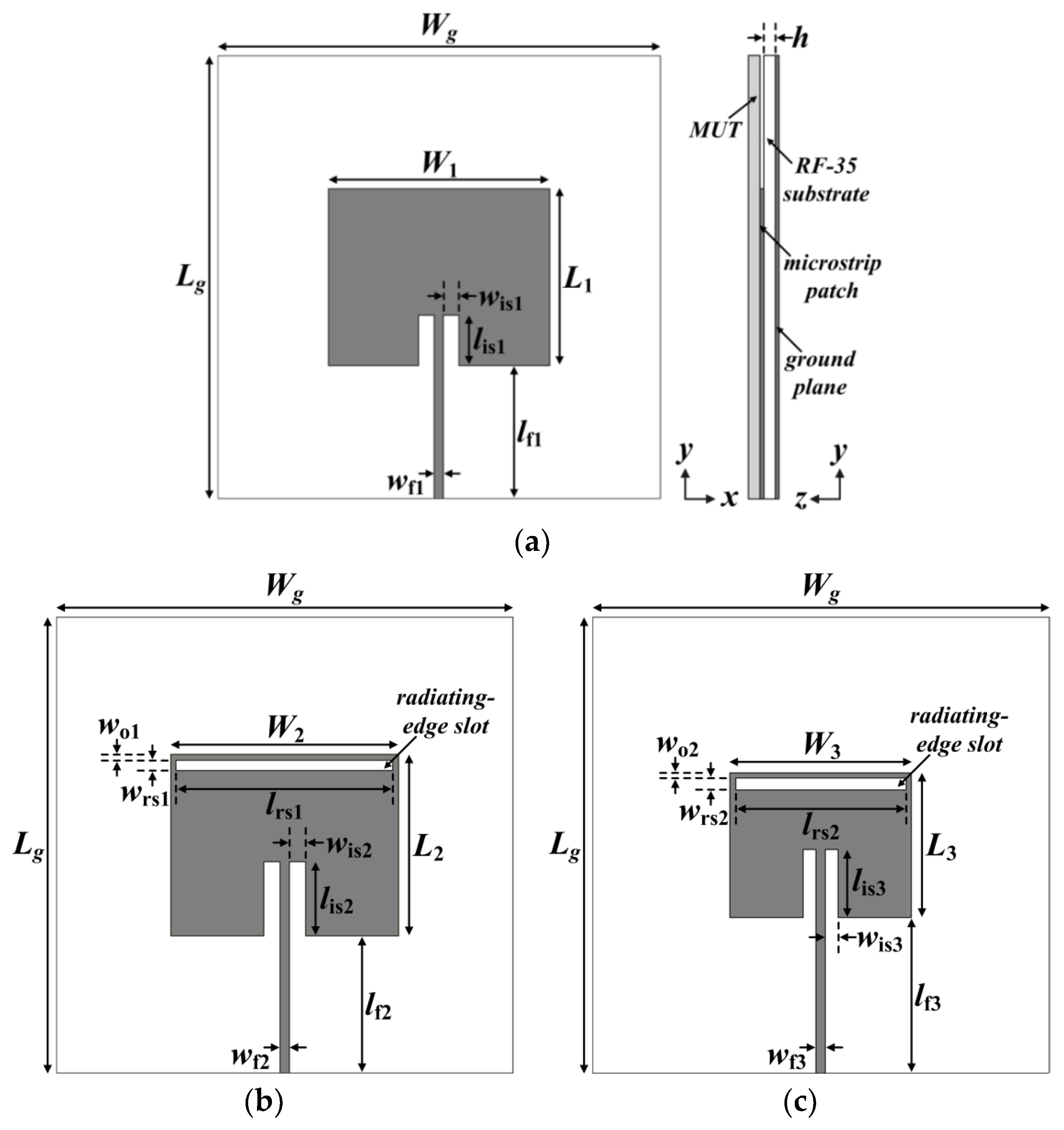
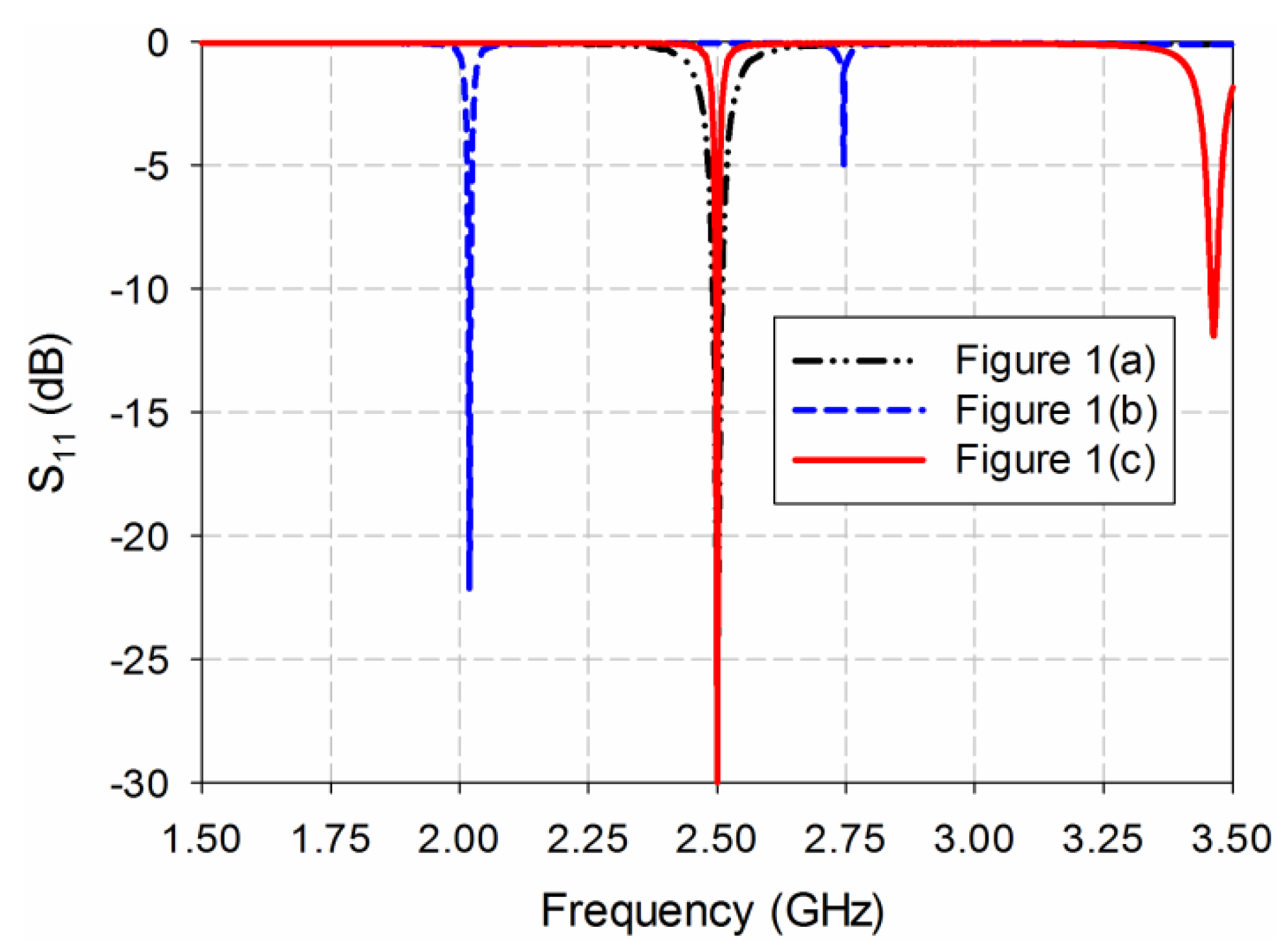
Figure 1 shows the geometries of a conventional inset-fed rectangular microstrip patch antenna, a slot-loaded rectangular microstrip patch antenna, and a scaled slot-loaded rectangular microstrip patch antenna. The corresponding input reflection coefficient characteristics (S
11) of the three antennas are shown in
Figure 2.
The conventional inset-fed rectangular microstrip patch antenna consisted of a rectangular patch with a 50-ohm microstrip feed line recessed inside the patch, and was printed on an RF-35 substrate (
εr = 3.5, tan
δ = 0.0018,
h = 0.76 mm), as shown in
Figure 1a. The width and length of the 50-ohm microstrip feed line were
wf1 = 1.66 mm and
lf1 = 24.5 mm, respectively. The width and length of the rectangular patch were
W1 = 40 mm and
L1 = 31.9 mm, respectively, to resonate at 2.5 GHz, as shown in
Figure 2. The width and length of the inset were
wis1 = 2.8 mm and
lis1 = 9 mm, respectively. The width and length of the ground plane were
W =
L = 80 mm. The MUT was placed above the patch as a superstrate for loaded conditions, as shown in
Figure 2a. The width and length of the rectangular patch were calculated by using the following related equations [
35]:
where
W and
L are the width and length of the rectangular patch,
εr is the relative permittivity of the substrate,
fr is the resonant frequency,
c is the speed of light in free space,
εreff is the effective relative permittivity,
h is the thickness of the substrate, and Δ
L is the extension of the patch length due to the fringing effects.
Next, a thin rectangular slot was etched along the radiating edge on the opposite side of the microstrip feed line in
Figure 1a, as shown in
Figure 1b. The widths and lengths of the patch, microstrip feed line, and ground plane were the same as those in
Figure 1a:
W2 =
W1,
L2 =
L1,
wf2 =
wf1, and
lf2 =
lf1. The width and length of the thin rectangular slot were
wrs1 = 1 mm and
lrs1 = 38 mm, respectively. The distance between the radiating edge and the thin rectangular slot was
wo1 = 1 mm. The width and length of the inset were
wis2 = 2.8 mm and
lis2 = 13 mm, respectively. It is well-known that dual resonant frequencies with similar radiating properties can be created when two narrow slots are inserted close to the radiating edges of the probe-fed patch [
36]. In addition, since the electric field distributions of the microstrip patch antenna are maximal at the radiating edges, the permittivity sensitivity of the patch antenna might be improved by adding slots along the radiating edges. When a thin rectangular slot was inserted along a radiating edge, two resonant frequencies were generated at
fr1 = 2.019 GHz and
fr2 = 2.746 GHz with a frequency ratio of
fr2/
fr1 = 1.36, which is similar to the results in [
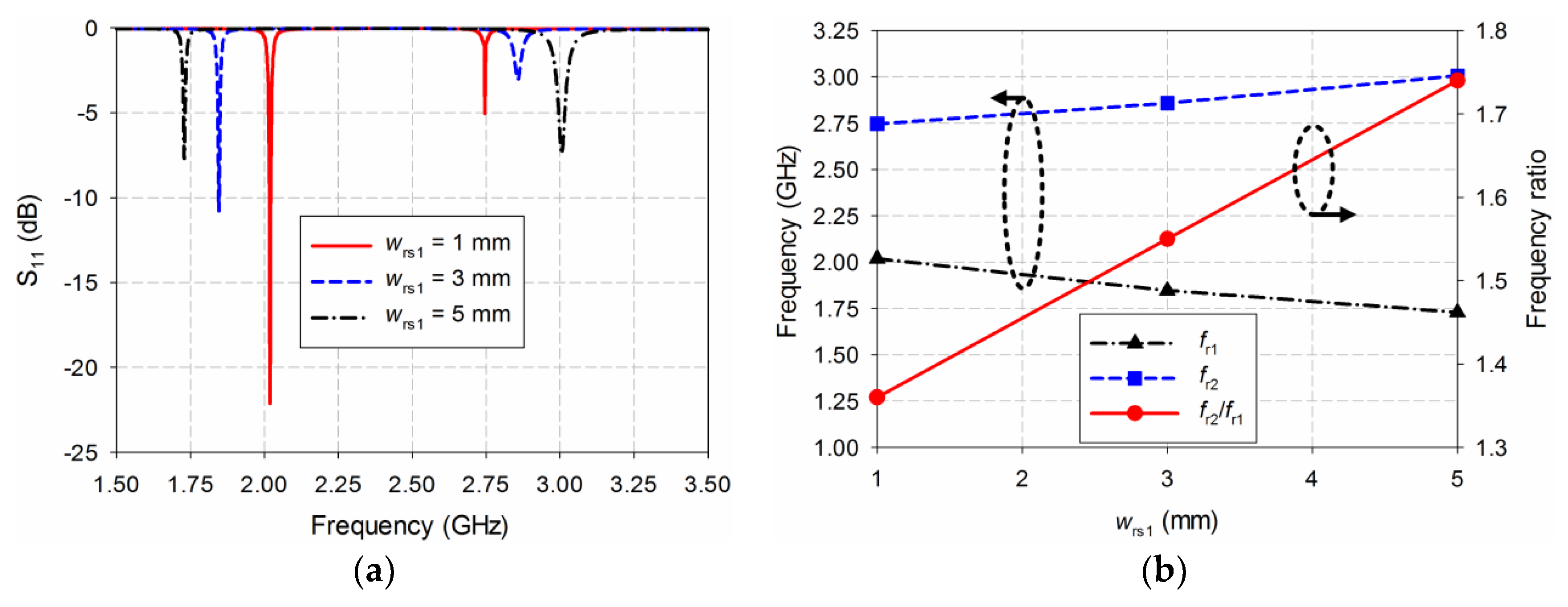
36]. The variations in the two resonant frequencies for different slot widths
wrs1 ranging from 1 mm to 5 mm are investigated in
Figure 3. When
wrs1 was increased to 3 mm, the first resonant frequency shifted to a lower frequency at
fr1 = 1.846 GHz, whereas the second resonant frequency moved to a higher frequency at
fr2 = 2.858 GHz. Therefore, the frequency ratio increased to
fr2/
fr1 = 1.55. As
wrs1 was further increased to 5 mm, the first resonant frequency moved further toward a lower frequency at
fr1 = 1.729 GHz, whereas the second resonant frequency shifted further toward a higher frequency at
fr2 = 3.006 GHz. The frequency ratio in this case becomes
fr2/
fr1 = 1.74. Hence, the first resonant frequency moved toward a lower frequency, and the frequency ratio between the first and second resonant frequencies increased as slot width
wrs1 increased.
Finally, the patch dimensions and slot length were scaled with a fixed slot width and distance of
wrs2 =
wo2 = 1 mm to have the first resonant frequency at 2.5 GHz to get the dielectric property at a common frequency compared to the conventional patch antenna in
Figure 1a, because the permittivity of a material is dispersive as a function of frequency. The width of the microstrip feed line, and the widths and lengths of the ground plane were the same as those in
Figure 1a (
wf3 =
wf1). The width and length of the scaled slot-loaded patch were
W3 = 31.8 mm and
L3 = 25.4 mm, respectively, to resonate at 2.5 GHz, as shown in
Figure 2. The patch dimensions were reduced about 20.4%, compared to those of the conventional patch antenna in
Figure 1a. The slot length was decreased to
lrs2 = 29.8 mm, whereas the length of the microstrip feed line was increased to
lf3 = 27.3 mm. The width and length of the inset were
wis3 = 2.3 mm and
lis3 = 12 mm, respectively. The first resonant frequency was
fr1 = 2.5 GHz, and the second was
fr2 = 3.465 GHz, as shown in
Figure 2. The frequency ratio in this case becomes
fr2/
fr1= 1.39, which was similar to that when the slot width was 1 mm. The frequency bandwidth of the first resonant frequency for a voltage standing wave ratio (VSWR) < 2 was 2.496–2.503 GHz, and its fractional bandwidth was 0.28%, which were quite reduced compared to the conventional patch antenna without slot loading (2.490–2.510 GHz, 0.8%) because of the size reduction of the slot-loaded patch. However, the quality factor at the first resonant frequency is increased to 357, compared to the conventional patch antenna (at 125).
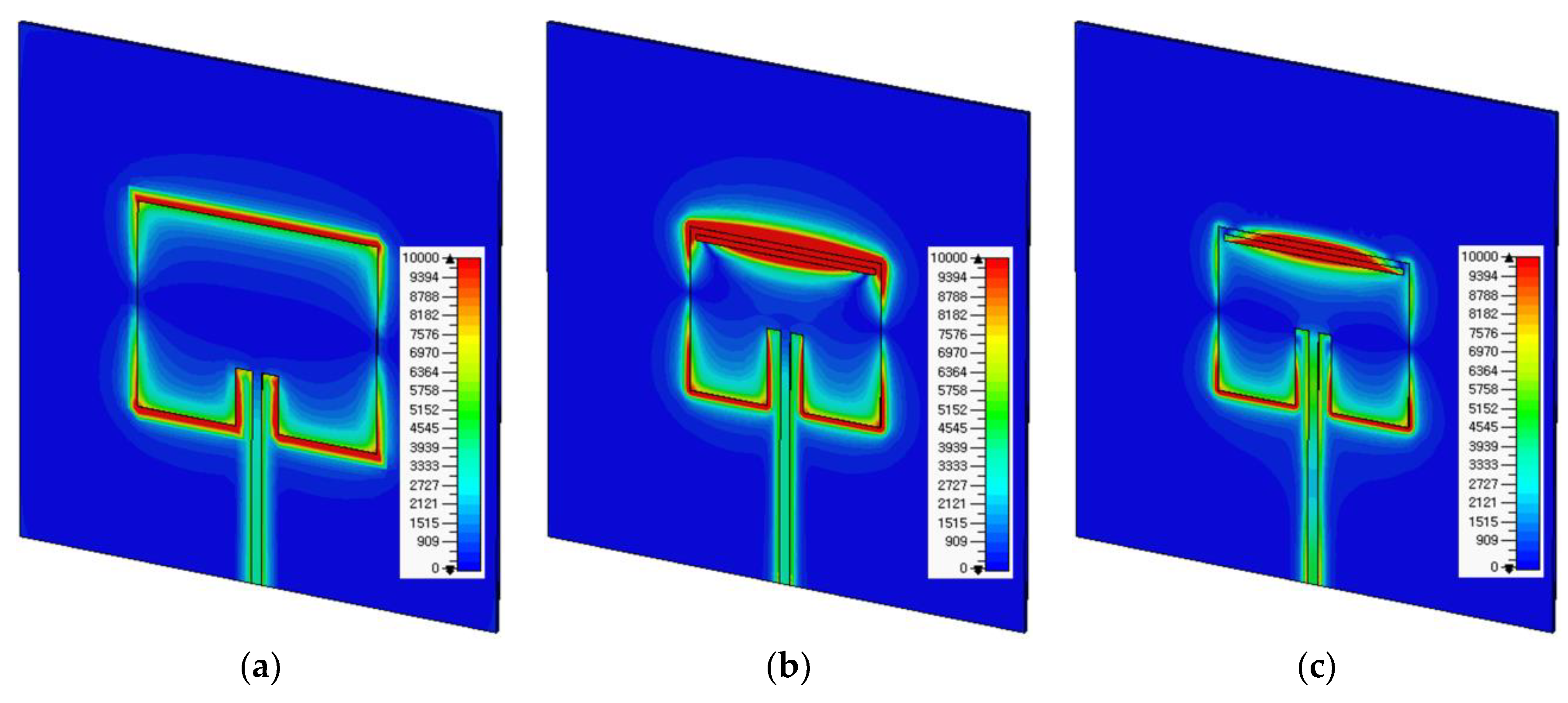
Figure 4 shows the electric field distributions of the conventional patch antenna and the proposed slot-loaded patch antenna. In the first resonant frequency of the proposed slot-loaded patch antenna, the electric-field distributions were more concentrated on the slot along the radiating edge, and this concentration area was more distributed compared to the first resonant frequency of the conventional patch antenna and the second resonant frequency of the slot-loaded patch antenna.
3. Sensitivity Comparison
In this section, the sensitivity of the scaled slot-loaded microstrip patch antenna in
Figure 1c is compared with the conventional patch antenna in
Figure 1a by measuring the shift in the resonant frequency of the input reflection coefficient.
Figure 5 shows the S
11 characteristics of the conventional patch antenna and the proposed slot-loaded patch antenna. The MUT was placed above the patch as a superstrate, and its relative permittivity (
εr) was varied from 1 to 10 in steps of 1. In this case, the loss tangent of the MUT was set to 0 as in the lossless case. The width and length of the MUT were the same as those of the ground plane, and its thickness was chosen to be 1.6 mm because the thickest of the substrates available from Taconic Inc., which were used as the MUTs, is around 1.6 mm. For the conventional patch antenna, the first resonant frequency (
fr1) for S
11 moved from 2.5 GHz to 2.312 GHz when
εr increased from 1 to 10, whereas it shifted from 2.5 GHz to 1.854 GHz for the proposed patch antenna. In addition, the second resonant frequency (
fr2) of the proposed patch antenna moved from 3.466 GHz to 2.991 GHz when
εr increased from 1 to 10.
Table 1 summarizes the resonant frequencies of the S
11 responses with a different relative permittivity of the MUT for the conventional and proposed patch antennas.
In order to compare the sensitivity performance of the proposed patch antenna with that of the conventional patch antenna, the shift in the resonant frequency (Δ
fr), percent relative frequency shift (PRFS), enhancement in percent relative frequency shift (PRFSE), sensitivity (S), and sensitivity enhancement (SE) of S
11 responses are defined as follows [
3,
12,
13,
37]:
where Δ
fr is the shift in the resonant frequency of the conventional and proposed patch antennas,
fru is the resonant frequency of the conventional and proposed patch antennas for unloaded conditions,
frl is the resonant frequency of the conventional and proposed patch antennas for loaded conditions, PRFS is the percent relative frequency shift of the resonant frequencies of the conventional and proposed patch antennas, PRFSE is the enhancement in the percent relative frequency shift of the first and second resonant frequencies of the proposed patch antenna compared to the conventional patch antenna, S is the sensitivity of the resonant frequencies of the conventional and proposed patch antennas with respect to the relative permittivity of the MUT,
εru is the relative permittivity of the MUT for unloaded conditions,
εrl is the relative permittivity of the MUT for loaded conditions, and SE is the sensitivity enhancement of the first resonant frequency of the proposed patch antenna compared to the conventional patch antenna.
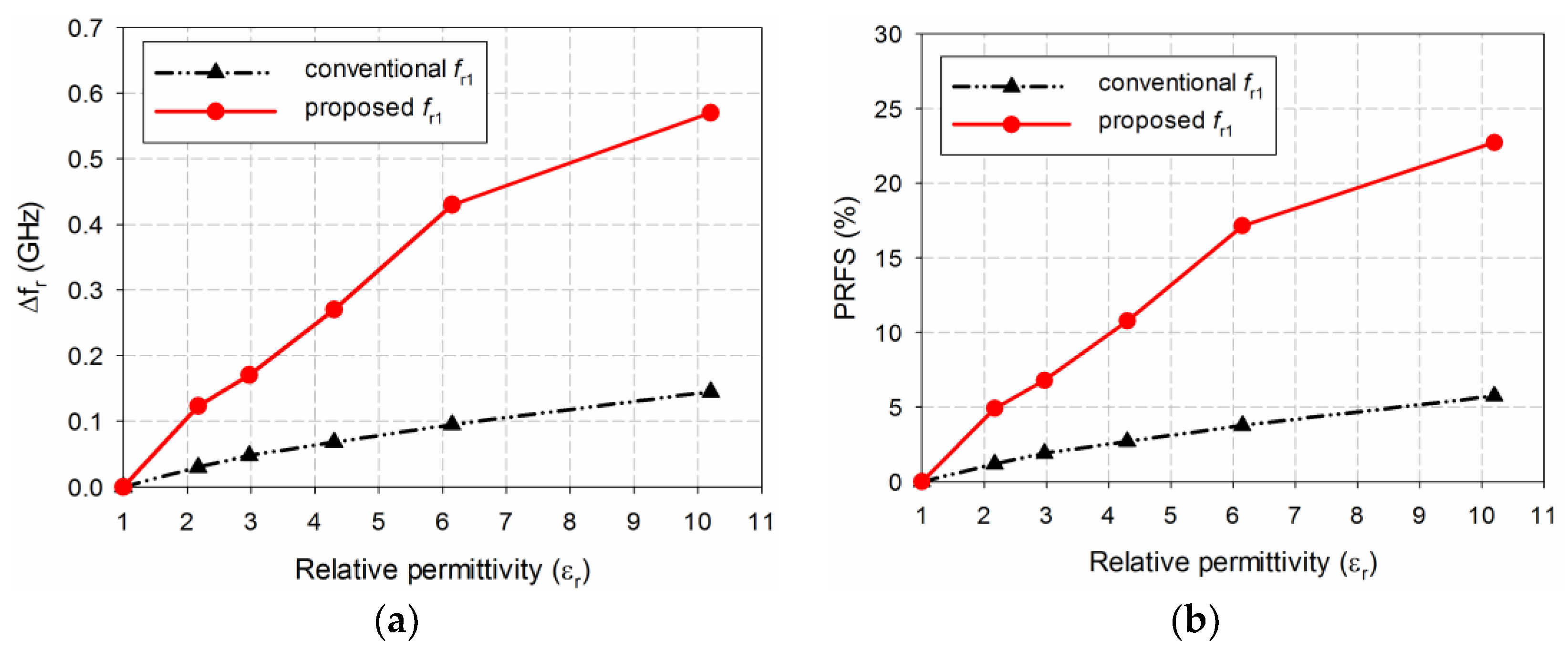
According to Equations (5)–(9), the sensitivity performance of the conventional and proposed patch antennas was analyzed from the results shown in
Figure 5 and
Table 1, and Δ
fr of S
11 for the conventional and proposed patch antennas is plotted in
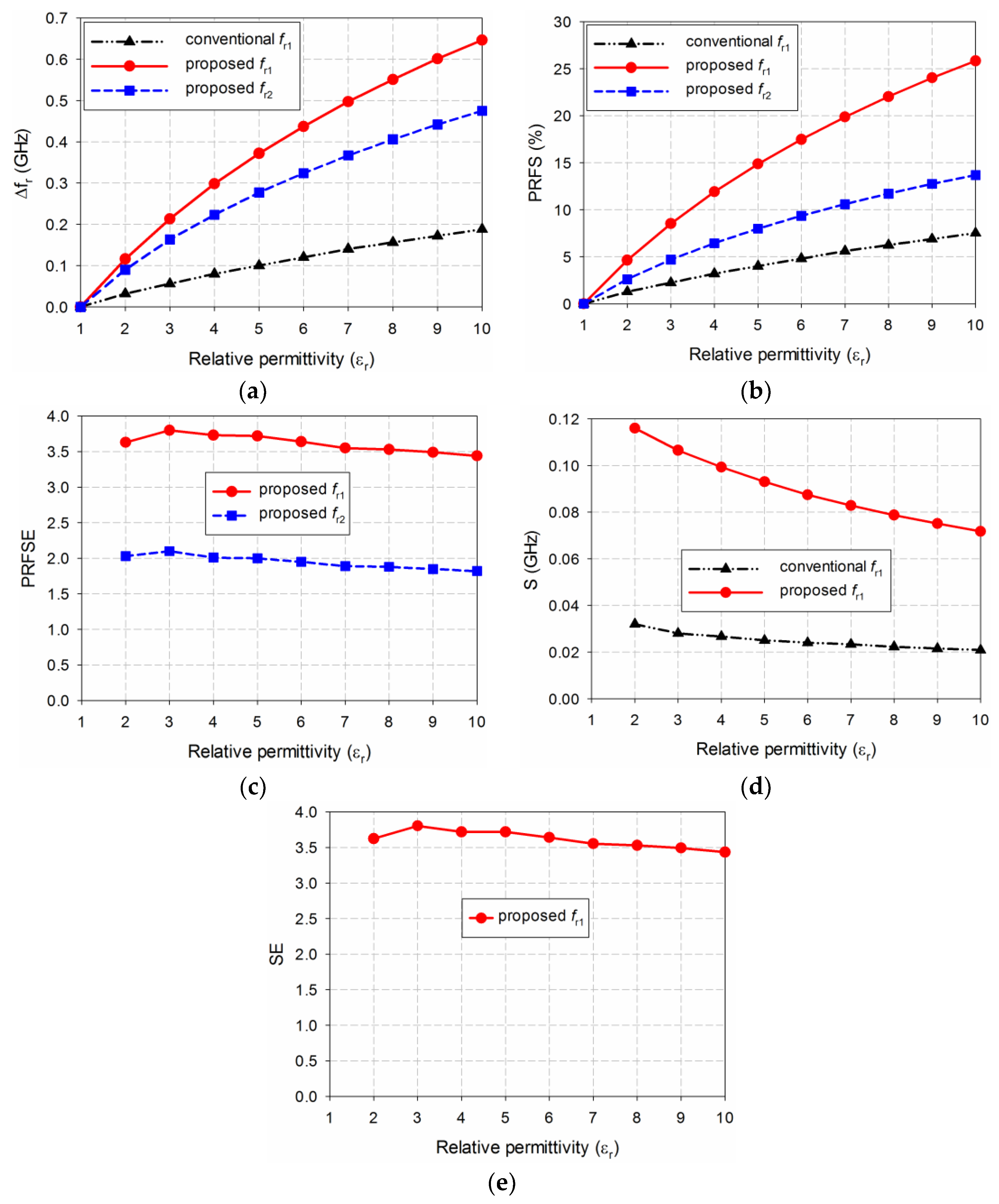
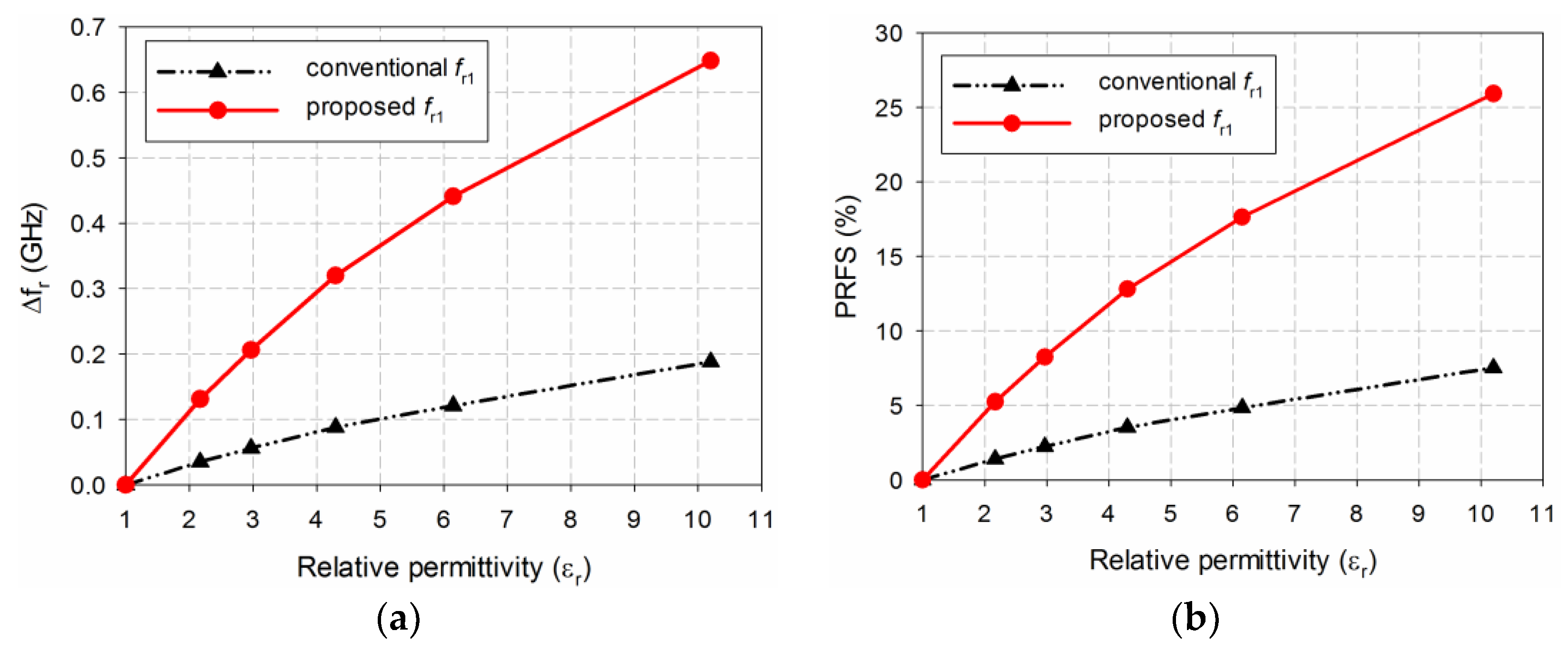
Figure 6a.
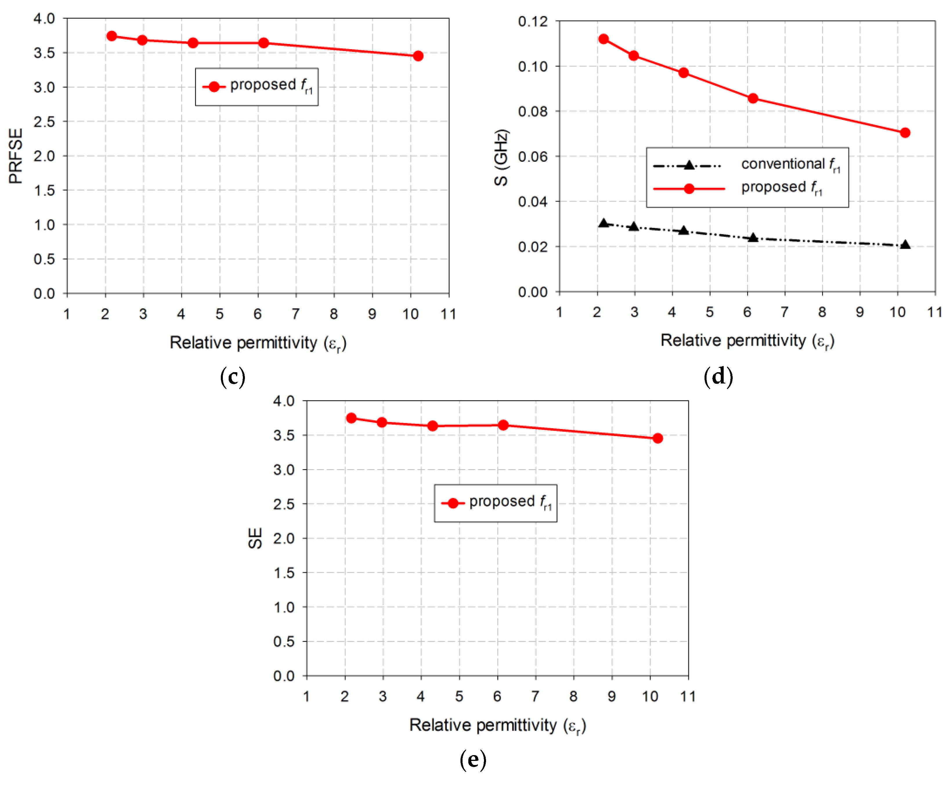
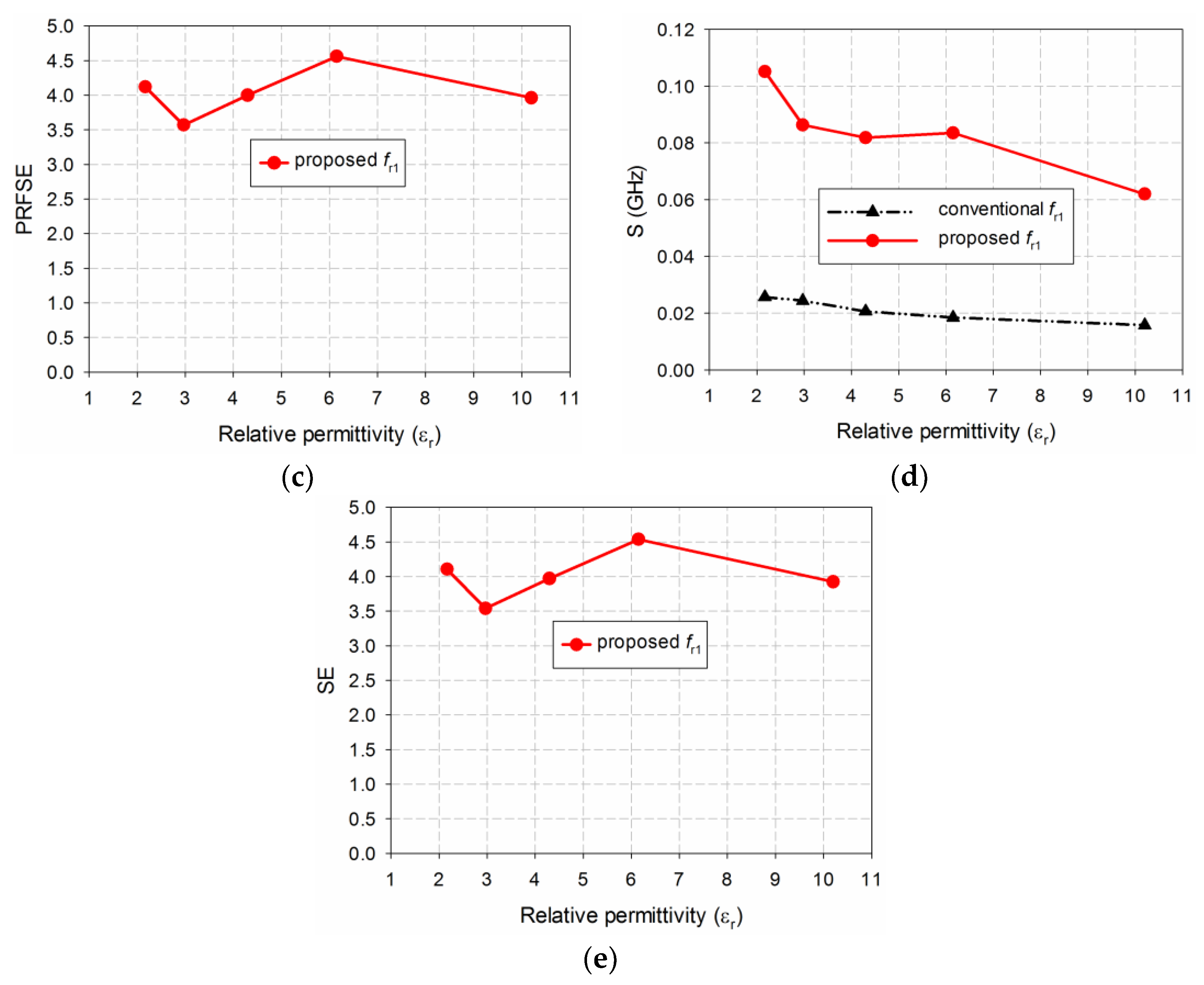
Figure 6b shows the PRFS of the conventional and proposed patch antennas. The PRFSE for the first and second resonant frequencies of the proposed patch antenna, compared to that of the first resonant frequency of the conventional patch antenna, is presented in
Figure 6c. Next, the S of the resonant frequencies of the conventional and proposed patch antennas is plotted in
Figure 6d.
Figure 6e presents the SE of the first resonant frequency of the proposed patch antenna compared to that of the conventional patch antenna. Note that the S and SE of the second resonant frequency of the proposed patch antenna are not plotted and compared in
Figure 6c,d because the second resonant frequency of the proposed patch antenna was different from the first resonant frequency of the conventional patch antenna, and their S and SE cannot be directly compared.
When the MUT was loaded above the patch, it affected the total capacitance and effective relative permittivity related to the microstrip patch resonator, and the S
11 resonant frequency was a nonlinear function of the resonator related to the effective relative permittivity [
23,
24]. We observe from
Figure 6d that sensitivity S was not constant as a function of relative permittivity, and it was higher for a smaller value of relative permittivity. For example, when the permittivity of the MUT was
εr = 2, frequency shift Δ
fr in the first resonant frequency of the conventional patch antenna was 0.032 GHz, whereas the first and second resonant frequencies of the proposed patch antenna were 0.116 GHz and 0.09 GHz. The PRFS in the first resonant frequency of the conventional patch antenna was 1.28%, whereas the first and second resonant frequencies of the proposed patch antenna were 4.64% and 2.6%. Therefore, the PRFSE for the first and second resonant frequencies of the proposed patch antenna were 3.63 and 2.03. In this case, S was the same as Δ
fr because the difference in the relative permittivity (Δ
εr) was 1. SE of the first resonant frequency of the proposed patch antenna was 3.63. It is worthwhile to note that the PRFSE was the same as SE. Hence, SE for the second resonant frequency of the proposed patch antenna could be compared by using PRFSE.
When the permittivity of the MUT was increased to εr = 10, frequency shift Δfr in the first resonant frequency of the conventional patch antenna was 0.188 GHz, whereas the first and second resonant frequencies of the proposed patch antenna were 0.646 GHz and 0.475 GHz. PRFS in the first resonant frequency of the conventional patch antenna was 7.52%, whereas the first and second resonant frequencies of the proposed patch antenna were 25.84% and 13.7%. PRFSE for the first and second resonant frequencies of the proposed patch antenna were 3.44 and 1.82. The S of the first resonant frequency of the conventional and proposed patch antenna were 0.021 GHz and 0.072 GHz, respectively. SE of the first resonant frequency of the proposed patch antenna was 3.44. Hence, we can conclude that the sensitivity of the proposed patch antenna at the first resonant frequency was 3.44 to 3.63 times higher than the conventional patch antenna for relative permittivity ranging from 2 to 10.
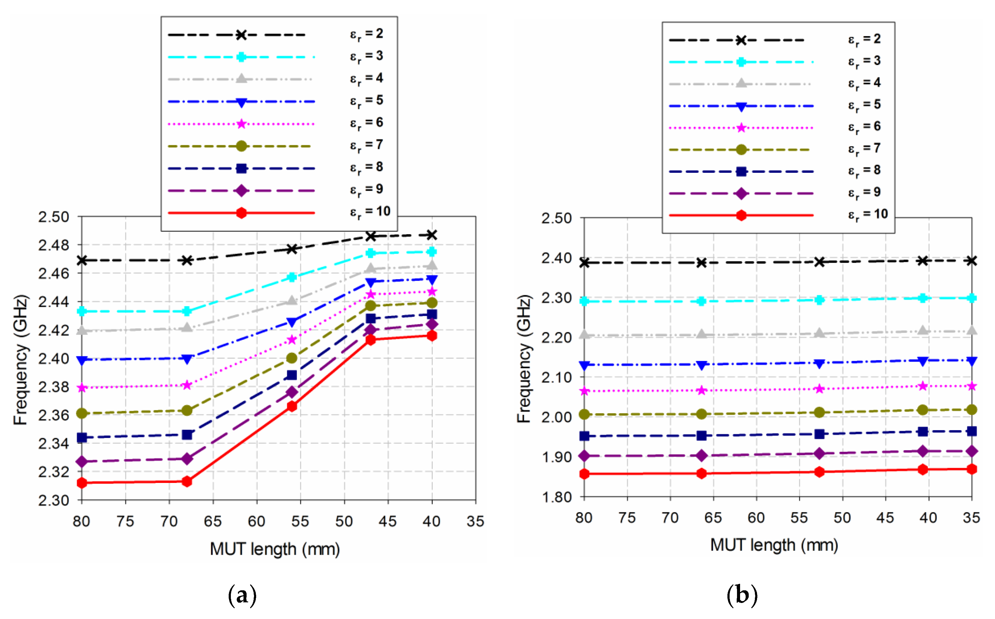
Next, in order to investigate the effect of covering the feed line of the microstrip patch antenna with the MUT on the resonant frequency of the antenna, the S
11 characteristics of the conventional and proposed patch antennas were compared when the length of the MUT was decreased from the input port of the antenna. For the conventional patch antenna, five different cases of the MUT length were simulated; 80 mm (=
Lg, the MUT completely covered the feed line), 68 mm (the MUT covered half the feed line), 56 mm (the MUT covered the patch with the inset feed part), 47 mm (the MUT covered the patch without the inset feed part), 40 mm (the MUT covered half of the patch). The variations on the resonant frequency of the conventional patch antenna for five cases of varying the MUT length are plotted in
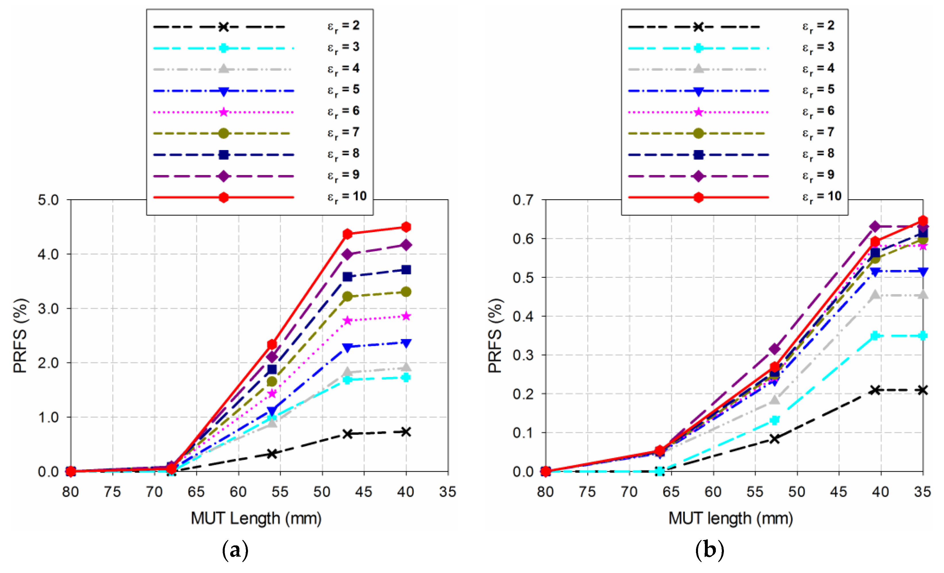
Figure 7a. The PRFS of the resonant frequency of the conventional patch antenna is shown in
Figure 8a. When the MUT length decreased from 80 mm to 68 mm, the shift in the resonant frequency was negligible, whereas the resonant frequency moved toward the high frequency linearly with an effect of sensitivity decrease when it further decreased to 56 mm and 47 mm. Note that the amount of the frequency shift increased as the relative permittivity of the MUT increased. For instance, when the permittivity of the MUT was
εr = 2, the PRFS in the first resonant frequency of the conventional patch antenna was 0.32% and 0.69% for the MUT length of 56 mm and 47 mm. When the permittivity of the MUT was increased to ε
r = 10, the PRFS in the first resonant frequency of the proposed patch antenna was 2.34% and 4.37% for the MUT length of 56 mm and 47 mm.
For the proposed patch antenna, five different cases of the MUT length were also simulated; 80 mm (=
Lg, the MUT covered completely the feed line), 66.4 mm (the MUT covered half the feed line), 52.7 mm (the MUT covered the patch with the inset feed part), 40.7 mm (the MUT covered the patch without the inset feed part), 35 mm (the MUT covered 30.3% of the patch). The variations on the resonant frequency of the proposed patch antenna for five cases of varying the MUT length are plotted in
Figure 7b and the PRFS of the resonant frequency of the proposed patch antenna is shown in
Figure 8a. When the MUT length decreased from 80 mm to 66.4 mm, the shift in the resonant frequency was negligible, whereas the resonant frequency moved toward the high frequency linearly when it further decreased to 52.7 mm and 40.7 mm. Note that the trend of the resonant frequency shift was similar to the conventional patch antenna, but the amount was relatively small. For example, when the permittivity of the MUT was
εr = 2, the PRFS in the first resonant frequency of the conventional patch antenna was 0.08% and 0.21% for the MUT length of 52.7 mm and 40.7 mm. When the permittivity of the MUT was increased to
εr = 10, the PRFS in the first resonant frequency of the proposed patch antenna was 0.27% and 0.59% for the MUT length of 52.7 mm and 40.7 mm.
The reason for this can be explained by the electric field distributions of the conventional and proposed patch antennas. For the conventional patch antenna, the electric fields were maxima at two radiating edges and, therefore, the covering region around both the two edges affected the resonant frequency of the antenna. However, for the proposed slot-loaded patch antenna, the electric fields were maxima nearby the loaded slot and the covering region nearby the slot would be enough. Hence, we can conclude that the proposed slot-loaded patch antenna had an advantage of relatively less effect on the MUT size for the resonant frequency shift and of using small size of the MUT compared to the conventional patch antenna.
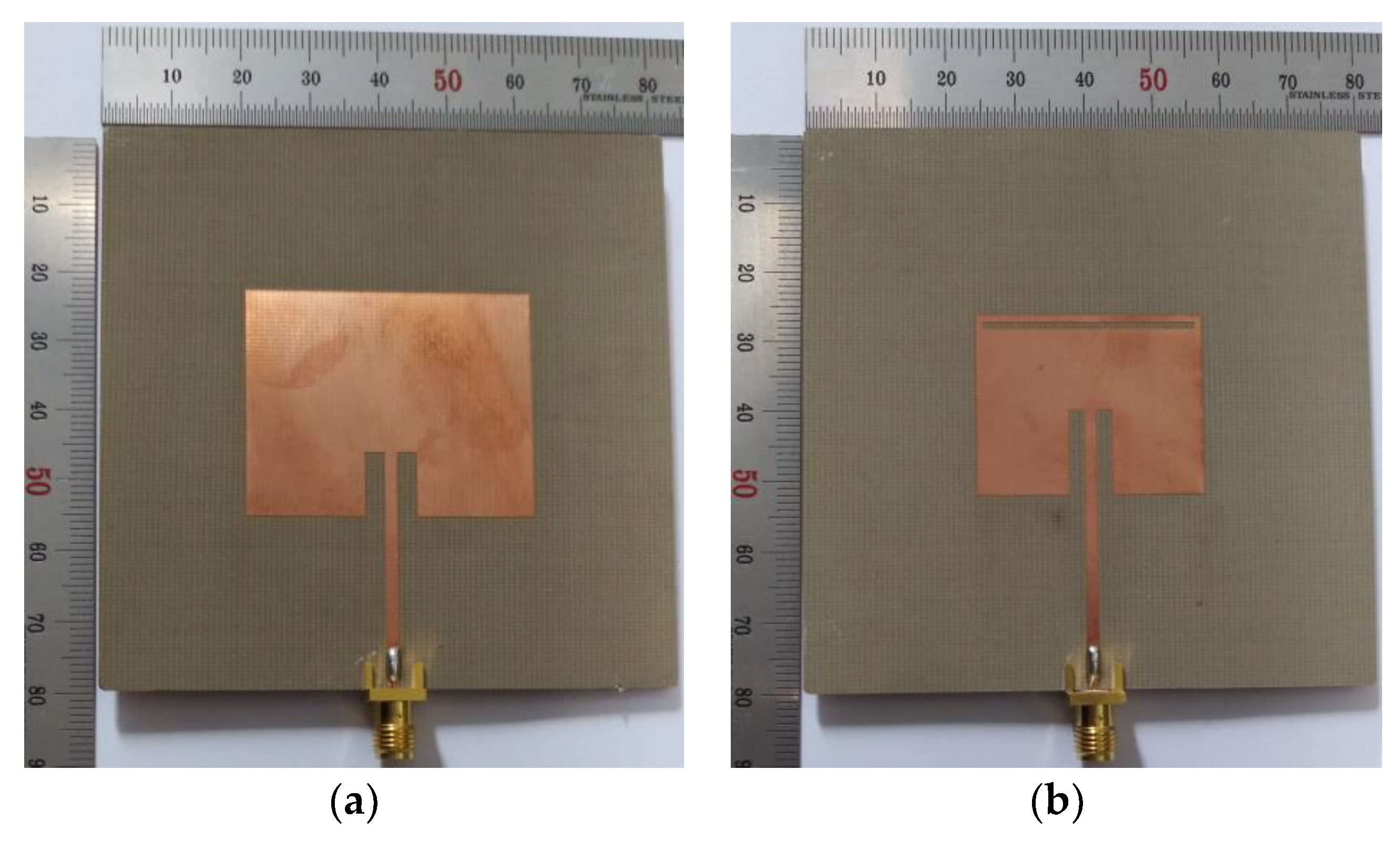
4. Experiment Results and Discussion
Prototypes of the conventional and proposed patch antennas described in the previous section were fabricated on an RF-35 substrate (
εr = 3.5, tan
δ = 0.0018,
h = 0.76 mm), as shown in
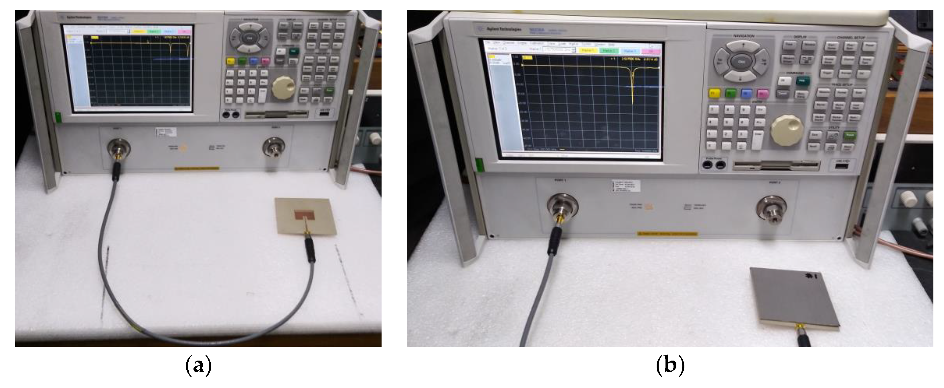
Figure 9. The S
11 characteristics of the fabricated antenna were measured using an Agilent N5230A network analyzer, and photographs of the experiment setup are shown in
Figure 10. Five different standard dielectric MUTs from Taconic Inc. (Petersburgh, NY, USA). were tested for the sensitivity comparison. The MUTs had relative permittivity ranging from 2.17 to 10.2, and their relative permittivity, loss tangent, and thickness from the data sheet in [
38] are summarized in
Table 2.
The S
11 characteristics of the conventional and proposed patch antennas were first simulated with the five MUTs in
Table 2 placed above the patch, as shown in
Figure 11. The length of the MUTs was slightly reduced to 75 mm because there is a protruding part in the subminiature version A (SMA) connector for soldering the input port of the fabricated antenna, as shown in
Figure 10b. For the conventional patch antenna, the first resonant frequency for S
11 moved from 2.465 GHz for the TLY-5A MUT (
εr = 2.17) to 2.312 GHz for the RF-10 MUT (
εr = 10.2). In the proposed patch antenna, the first resonant frequency shifted from 2.369 GHz for the TLY-5A to 1.852 GHz for the RF-10.
Table 3 shows the first resonant frequencies of the simulated S
11 responses for the conventional and proposed patch antennas.
Figure 12 compares the simulated sensitivity for the first resonant frequencies of the conventional and proposed patch antennas when the five MUTs are loaded. When TLY-5A (
εr = 2.17) was used as the MUT, the first resonant frequency shifts Δ
fr of the conventional and proposed patch antennas were 0.035 GHz and 0.131 GHz, and the PRFS were 1.4% and 5.24%. The PRFSE for the first resonant frequency of the proposed patch antenna is 3.74. The S of the conventional and proposed patch antennas were 0.030 GHz and 0.112 GHz. The SE of the proposed patch antenna was 3.75. When RF-10 (
εr = 10.2) was used as the MUT, the first resonant frequency shifts Δ
fr of the conventional and proposed patch antennas were 0.188 GHz and 0.648 GHz, respectively, and the PRFS were 7.52% and 25.92%. The PRFSE for the first resonant frequency of the proposed patch antenna was 3.45. The S in the conventional and proposed patch antennas were 0.020 GHz and 0.070 GHz, respectively. The SE of the proposed patch antenna was 3.45. Therefore, the trends in Δ
fr, PRFS, PRFSE, S, and SE for the five MUTs were similar to those of the lossless case in
Figure 6, and the only difference was the loss tangent. Since the loss tangent of the MUT influences the bandwidth or the quality factor of the S
11 characteristics of the patch antennas [
23,
24], and the loss tangent of the MUTs is moderately low, ranging from 0.009 to 0.035, the effect of the low tangent on the S
11 resonant frequencies would not be significant.
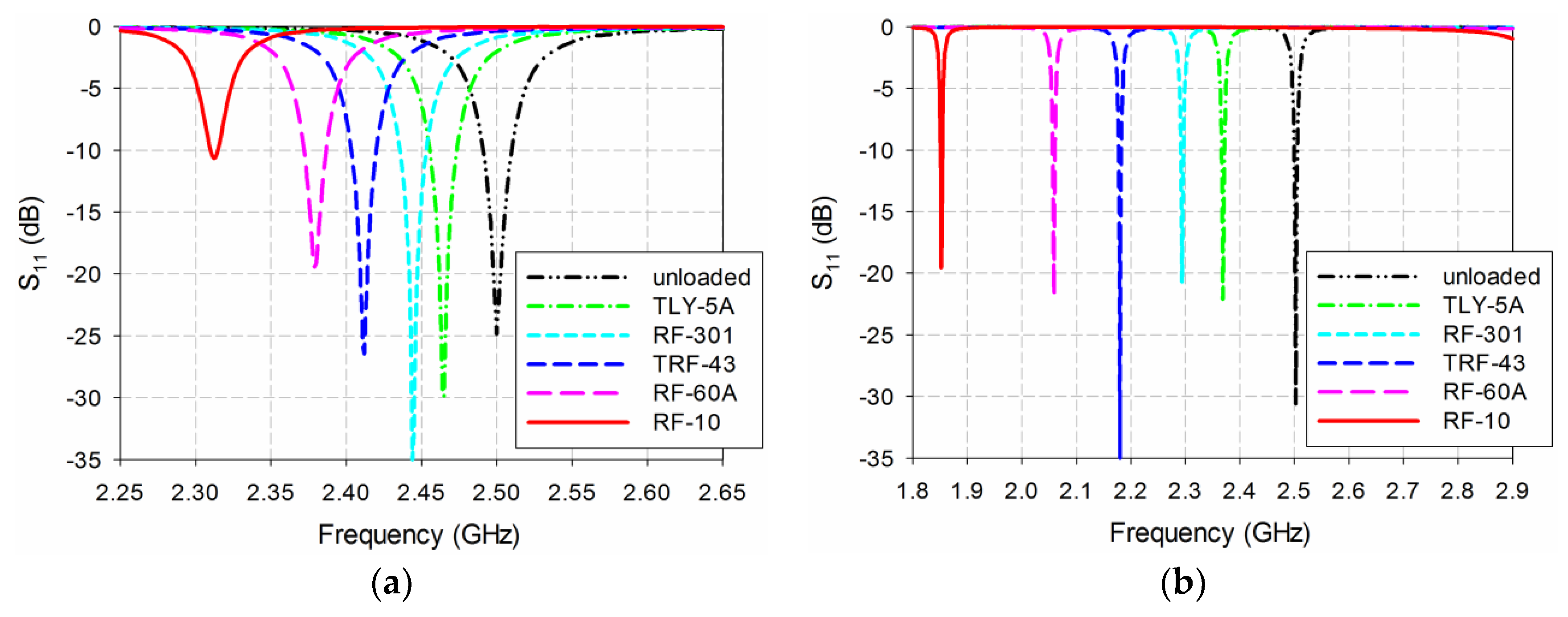
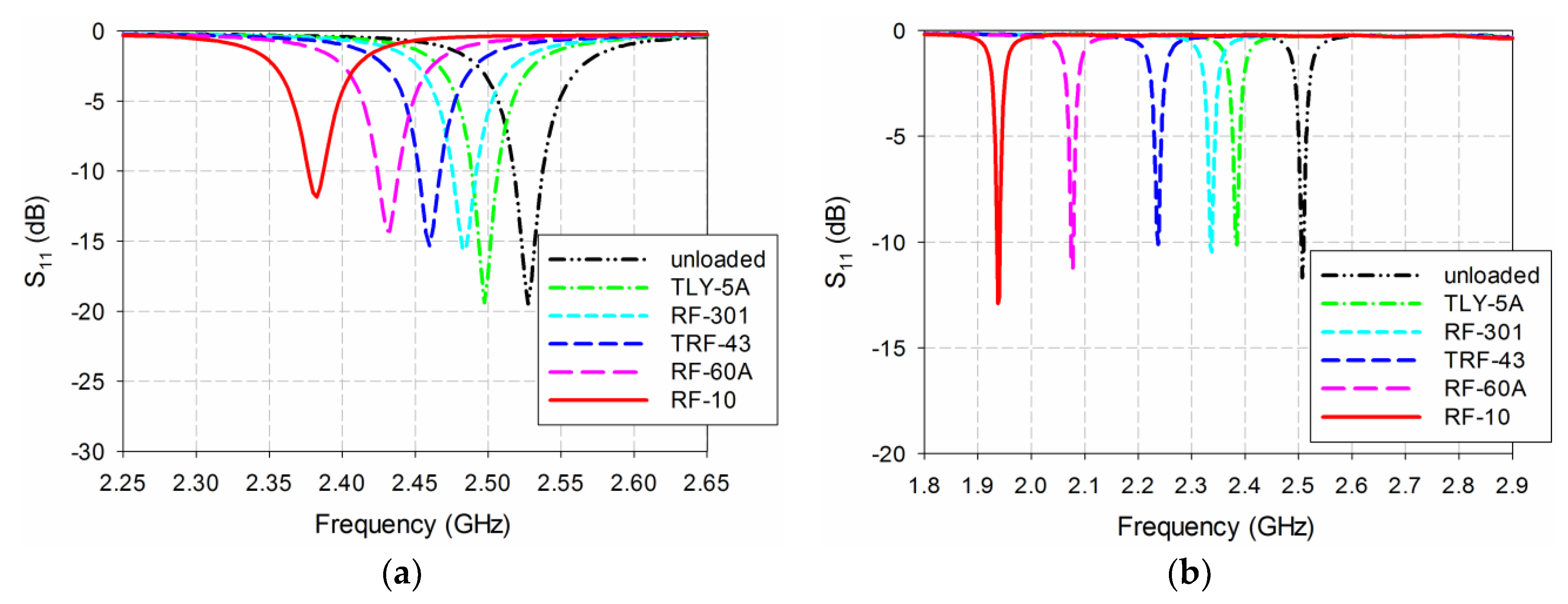
Next, the simulated sensitivity of the conventional and proposed patch antennas was validated by measuring their S
11 characteristics when the five MUTs in
Table 2 were placed above the patch, as shown in
Figure 13. The length of the MUTs was slightly reduced to 75 mm. When unloaded, the first S
11 resonant frequencies of the conventional and proposed patch antennas were 2.528 GHz and 2.508 GHz, respectively, which were close to the simulated resonant frequency of 2.5 GHz. The respective errors compared to the simulated first resonant frequency when unloaded were 1.12% and 0.32%, which might have been caused by errors in fabrication and measurement. For the conventional patch antenna, the first resonant frequency of S
11 moved from 2.498 GHz for the TLY-5A to 2.383 GHz for the RF-10, while it moved from 2.385 GHz for the TLY-5A to 1.938 GHz for the RF-10 in the proposed patch antenna.
Table 4 summarizes these results.
The measured sensitivities for the first resonant frequencies of the conventional and proposed patch antennas are compared in
Figure 14. When TLY-5A (
εr = 2.17), RF-301 (
εr = 2.97), TRF-43 (
εr = 4.3), RF-60A (
εr = 6.15), and RF-10 (
εr = 10.2) were used as the MUT, in turn, the first resonant frequency shifts, Δ
fr, of the conventional patch antennas were 0.030 GHz, 0.048 GHz, 0.068 GHz, 0.095 GHz, and 0.145 GHz, respectively, whereas those of the proposed patch antenna were 0.123 GHz, 0.170 GHz, 0.270 GHz, 0.430 GHz, and 0.570 GHz, respectively. The PRFS for the conventional patch antennas were 1.19%, 1.90%, 2.69%, 3.76%, and 5.74%, respectively, whereas the proposed patch antenna showed 4.90%, 6.78%, 10.77%, 17.15% and 22.73%, respectively. The PRFSE values for the first resonant frequency of the proposed patch antenna were 4.12, 3.57, 4.00, 4.56 and 3.96, respectively. The S values in the conventional patch antennas were 0.026 GHz, 0.024 GHz, 0.021 GHz, 0.018 GHz, and 0.016 GHz, respectively, whereas those in the proposed patch antenna were 0.105 GHz, 0.086 GHz, 0.082 GHz, 0.083 GHz, and 0.062 GHz, respectively. The SE values in the proposed patch antenna were 4.11, 3.54, 3.97, 4.53 and 3.92, respectively. Hence, the measured sensitivity of the proposed patch antenna was 3.54–4.53 times higher than the conventional patch antenna for the five MUTs, with relative permittivity ranging from 2.17 to 10.2, which was a slight increase, compared to the simulated results, due to fabrication and measurement errors.
The differences in measured and simulated PRFS for the low permittivity MUT of the TLY-5A MUT were low at 0.21% to 0.34%, but the differences increased to 1.78% to 3.19% for the RF-10, which had high permittivity. In order to study the reasons for the differences in measured and simulated PRFS and the increasing error in the PRFS for the high permittivity MUT (RF-10), the simulated S
11 characteristics of the conventional and proposed patch antennas were compared when the air gap between the MUT and the patch increased from 0 to 2 mm. For simulation, 18 different cases of the air gap were considered; 0, 0.005, 0.01, 0.02, 0.05, 0.1, 0.15, 0.2, 0.3, 0.4, 0.5, 0.6, 0.7, 0.8, 0.9, 1.0, 1.5, 2.0 (units in millimeter). First, the variations on the resonant frequency of the conventional patch antenna for 18 cases of varying the air gap are plotted in
Figure 15a. The PRFS of the resonant frequency of the conventional patch antenna is shown in
Figure 16a. When the air gap increased from 0 mm to 2 mm, the shift in the resonant frequency moved toward the high frequency with a nonlinear behavior. Note that the slope of the resonant frequency shift was higher for small air gap less than 0.2 mm and the amount of the frequency shift increased as the relative permittivity of the MUT increased. For instance, when TLY-5A was used as the MUT, PRFS of the conventional patch antenna was 0.30% for the air gap of 0.1 mm, whereas it was increased to 2.81% when RF-10 MUT was used.
For the proposed patch antenna, the variations on the resonant frequency for 18 cases of varying the air gap are plotted in
Figure 15b and the PRFS of the resonant frequency is shown in
Figure 16b. We observe that the trend of the resonant frequency shift was similar to the conventional patch antenna, but the amount was relatively large, which means more sensitive to the air gap. For example, when TLY-5A was used as the MUT, the PRFS of the proposed patch antenna was 2.03% for the air gap of 0.1 mm, whereas it was increased to 17.17% when RF-10 MUT was used. Therefore, the increasing error in the PRFS for the high permittivity MUT was observed by the simulation of the air gap between the MUT and the patch. In addition, the proposed patch antenna sensor was more sensitive to the air gap variation compared to the conventional patch antenna. In fact, plastic clips were used to fasten the MUT to the patch antenna, but it seems like that the pressure between the MUT and the antenna was not enough to guarantee perfect contact between the MUT and the antenna. Hence, imperfect contact or a small air gap between the MUT and the antenna sensor made the error between the simulated and measured results. We will try to develop an accurate air gap control fixture or system for future work. The proposed slot-loaded patch antenna sensor can also be used for proximity detection applications by using the air gap variation.


