Abstract
Multidirected acyclic graph (DAG) workflow scheduling is a key problem in the heterogeneous distributed environment in the distributed computing field. A hierarchical heterogeneous multi-DAG workflow problem (HHMDP) was proposed based on the different signal processing workflows produced by different grouping and scanning modes and their hierarchical processing in specific functional signal processing modules in a multigroup scan ultrasonic phased array (UPA) system. A heterogeneous predecessor earliest finish time (HPEFT) algorithm with predecessor pointer adjustment was proposed based on the improved heterogeneous earliest finish time (HEFT) algorithm. The experimental results denote that HPEFT reduces the makespan, ratio of the idle time slot (RITS), and missed deadline rate (MDR) by 3.87–57.68%, 0–6.53%, and 13–58%, respectively, and increases relative relaxation with respect to the deadline (RLD) by 2.27–8.58%, improving the frame rate and resource utilization and reducing the probability of exceeding the real-time period. The multigroup UPA instrument architecture in multi-DAG signal processing flow was also provided. By simulating and verifying the scheduling algorithm, the architecture and the HPEFT algorithm is proved to coordinate the order of each group of signal processing tasks for improving the instrument performance.
1. Introduction
Ultrasonic phased array (UPA) systems with a large number of elements can achieve multigroup scanning, increase the scanning flexibility, and enhance the resolution and contrast of the resulting images. Hierarchical signal processing flow that accounts for the constraints of a directed acyclic graph (DAG) can be realized by adding a bus and an arbitrator to the hardware architecture. In a distributed software environment, multigroup UPA scans can use different scanning modes in different groupings; thus, several different signal processing methods can be implemented. These processes must also be hierarchically processed using the heterogenous shared resources according to the priority constraints. The priority constraints between the tasks in each group are represented using the DAG diagrams, and each shared resource can only perform the specified signal processing tasks because of functional constraints. Further, the priority constraints related to the multigroup tasks combine with the functional constraints on shared resources to form a hierarchical heterogeneous multi-DAG workflow problem (HHMDP). To address this problem, a scheduling algorithm is required to coordinate task processing with the heterogeneous shared resources so that the various signal processing steps involved in the distributed UPA instruments can be executed in an orderly manner.
With the rapid development of information technology and the increasing complexity of the associated problems, distributed computing resources with high performance are required to complete the computing tasks subject to the deadline constraints. Further, distributed resource scheduling for DAG tasks has been the subject of several previous researches and has developed into a mature method. More than 100 scheduling algorithms have been developed based on the homogeneous or heterogeneous distributed environments, the structural differences of the scheduling tasks, and the different optimization objectives [1]. Among these algorithms, the DAG scheduling model and the heterogeneous earliest finish time (HEFT) algorithm proposed by Topcuoglu [2] in 2002 have been extensively adopted. These are the models and methods that have been recently employed in distributed systems for performing tasks such as grid and cloud computing.
An existing study has denoted that the DAG scheduling problem is a nondeterministic polynomial complete problem [3]. Further, popular task scheduling algorithms used to obtain the makespan can be classified into the following two categories: static scheduling and dynamic scheduling algorithms [4]. Among the static scheduling algorithms, the list scheduling algorithms that employ heuristic techniques have been proved to produce the most efficient scheduling, and their complexities, associated with the number of involved tasks involved, are generally quadratic [5]. In addition, the list scheduling algorithm is fast, easy to implement, and has wider applicability than that of other scheduling algorithms. Some of the most famous list scheduling algorithms are HEFT [2], predicted earliest finish time (PEFT) [3], heterogeneous critical parent tree (HCPT) [6], high-performance task scheduling (HPS) [7], and performance effective task scheduling (PETS) [8]. HEFT is known to produce a scheduling length that can be compared with that produced by other scheduling algorithms exhibiting a lower time complexity. Further, the HEFT algorithm can be enhanced by either introducing a new mechanism for calculating the task priority or adding a new mechanism (such as prior attributes) to improve the processor selection [9].
The idle time slot of a single DAG task is large, and its resource utilization is low owing to the data transmission delay between the tasks and the imbalanced DAG structure. To effectively improve these shortcomings, Honig [10] and H. Zhao [11] initially proposed a scheduling algorithm in 2006 for multi-DAGs sharing a set of distributed resources. A DAG task can use idle slots generated by other DAG tasks scheduled on the same distributed resource group. Further, strategies to minimize makespan and scheduling fairness were also proposed. Although Yu et al. [12] made some improvements in this regard, the multi-DAG scheduling algorithm proposed in their study did not consider the deadline constraints. By considering the earliest deadline first (EDF) [13] algorithm—an application of the sequential scheduling algorithm based on the deadline—Stavrinides [14] proposed the usage of the deadline of each DAG for determining the priority of the multi-DAG task scheduling and the usage of the time slots for accurate calculation of the DAG tasks. This approach is suitable for DAGs with similar DAG structures and sizes. However, the deadline is insufficient to respond to the emergency of DAG because the number of DAG tasks is different. Furthermore, the relative strictness of Multi-DAGs with deadlines (MDRS) [15] scheduling strategy improves the fairness of scheduling according to the relative strictness of each DAG. However, before the scheduling tasks are selected, the HEFT algorithm is used to preschedule the remaining tasks for each DAG after which the relative duration of each DAG is calculated, and the most urgent task in the DAG is scheduled for execution. Therefore, each DAG can decentralize hybrid scheduling before the deadline, thereby improving resource utilization. However, some DAGs would be discarded when resource shortage is observed. Tian et al. [16] improved the existing fair scheduling algorithm by solving the fairness problem that is encountered while scheduling multiple DAG workflows that have the same priority but are submitted at different times. In addition, Xu et al. [17] proposed a cooperative scheduling algorithm to further improve the utilization of the computing resources for the workflow in a distributed heterogeneous environment exhibiting better performance in terms of throughput, time slot wastage, fairness, and time complexity when compared with those exhibited by MDRS, EDF, and fairness algorithms.
For ultrasonic phased array and DAG workflow scheduling, Tang et al. [17] studied ultrasonic bus transmission scheduling using the MFBSS algorithm to schedule between FIFOs, so that the utilization rate of transmission channels was not less than 92%. Li et al. [18], based on time division multiplexing, proposed an IBF algorithm for focus and delay module scheduling, which increased the maximum completion time by 8.76 to 21.48%, reduced resource consumption by 30 to 40%. Li et al. [19] also proposed SSPA algorithm for heterogeneous signal processing. Compared with the FCFS algorithm and SPT algorithm, the SSPA algorithm improves bandwidth utilization by 9.72% and reduces maximum completion time by 11%. Anwar and Deng [20] proposed a novel Hybrid Bio-inspired Metaheuristic for Multiobjective Optimization (HBMMO) algorithm based on a nondominant sorting strategy for the workflow scheduling problem, which decrease makespan, execution cost, and inefficient utilization of the virtual machines (VMs). Miao et al. [21] investigates H∞ consensus problem of heterogeneous multiagent systems under Markov switching topologies; consensus algorithms with communication time delay via output were also proposed. By applying stochastic stability analysis, model transformation techniques and graph theory, sufficient conditions of mean square consensus and H∞ consensus are obtained, respectively. Drozdov [22] address image processing workflow scheduling problems on a multicore digital signal processor cluster. They proposed Pessimistic Heterogeneous Earliest Finish Time scheduling algorithm for Ligo and Montage applications and presented its better performance than others. Feng et al. [23] studied gene function prediction, which includes the hierarchical multilabel classification (HMC) task, and proposed an algorithm for solving this problem based on the Gene Ontology (GO), the hierarchy of which is a directed acyclic graph (DAG). The algorithm has better performance compared with true path rule and CLUS-HMC algorithm on eight yeast data sets annotated by the GO.
However, these scheduling algorithms do not consider the challenge in performing heterogeneous resource processing tasks at different layers using different resources, i.e., some processors can only handle specific tasks, and these tasks or transactions can be sequentially executed if a single DAG can be approximated as a distributed permutation flow shop scheduling problem in a distributed environment and if the processor selection phase can be considered to be hierarchical. Thus, in general, there exists little research and few achievements related to the multi-DAG hierarchical scheduling problem and its application in the signal processing scheduling of ultrasonic systems even though many related problems require urgent attention. This study uses the critical path method by considering the hierarchical and specified function constraints of the shared resources to propose an improved method for HEFT that incorporates predecessor pointer adjustment (PPA), which can be referred to as the heterogeneous predecessor earliest finish time (HPEFT). This method can coordinate the different signal processing steps to satisfy the priority constraints represented by the multi-DAG model under the multigroup scanning architecture of a UPA system with multiple layers and shared resources for performing the specified functions. This coordination reduces the maximum completion time (makespan) and improves the utilization rate of the shared resources, improving the real-time frame rate and reducing the energy consumption.
The remainder of the manuscript is organized as follows. Section 2 discusses the hierarchical heterogeneous multi-DAG workflow scheduling problem and presents both the previous and proposed algorithms along with some basic examples; Section 3 discusses the experimental settings, problem generators, parameters, the experiments performed herein, and the results; Section 4 presents the signal processing scheduling optimization strategies for a multigroup scan UPA system; and Section 5 summarizes this study and discusses future work.
2. A Hierarchical Heterogeneous Multi-DAG Workflow Problem (HHMDP) and HPEFT Algorithm
2.1. Problem Description
Suppose there are multiple workflows that can be modeled as DAG {Gk, k ∈ 1, 2…K}. Each DAG node, ki, represents a task, Tki, and each edge represents the sequential relation between two different nodes. Thus, it can be said that ki exhibits a hierarchical structure. The nodes belonging to the first layer have no predecessor nodes, and they have start time STki. The tasks in the first layer must wait until the specified STki before they can be executed by the processor. Further, the tasks in the final layer have no successor nodes. All the nodes must be dispatched to a collection of heterogeneous shared resources M = {{Mjl, j = 1, 2…Ql}, l = 1, 2, 3…L}; the set of shared resources for each layer of Mjl contains several shared resources that can execute the corresponding layer nodes. The shared resources in a layer can only perform tasks corresponding to the nodes in the same layer, and the nodes in the same layer to be executed by the shared resource must belong to the same layer. Further, the nodes in the same DAG have a sequential relation. With the exception of the first and the final layer nodes, the remaining nodes in a DAG must have predecessor and successor nodes and cannot be isolated from other nodes. A node can have multiple predecessor and successor nodes, and its predecessor nodes can only be in the upper layer, whereas its successor nodes can only be in the subsequent layer. However, a node cannot be both the predecessor and successor node of another node simultaneously. All the tasks must be sequentially processed according to the DAG graph, and the computing tasks of the upper node must be processed before the current node can be processed. For any given node, the processing time Pki for the computing tasks is determined by the data length Dki in the node, as follows
Pki = Dki/SDj + Cj.
The difference in Dki and the shared resource speed, SDj, can change the execution time of a given node Pki,j. Cj is the delay that is required for the current processor to run. The delay is considered to be generally small. The system used in the present research was interconnected by buses with the following conditions. The tasks of the same node cannot be executed twice on the same shared resource, and the predecessor or successor nodes of any given node cannot be executed on the same shared resource because the hierarchical structure is in different sets of shared resources. Therefore, in the problem that is considered herein, the delay is not equivalent to the communication time, as observed in the case of a classical HEFT algorithm. Hence, we propose a strategy, which ensures that each node produces Cj in any processor, with the communication time for shared resource switching observed to be zero.
Each shared resource in the system can be simultaneously executed and communicated. The scheduling problem is to minimize the makespan. Furthermore, the DAG actual finish time (DAFT) after the scheduling of the algorithm represents the makespan after all the nodes in a DAG are executed.
makespan = max{DAFT(ki), where ki is the latest execution node in DAG}
The maximum number of layers of tasks (node) from the top to the bottom of the DAG and the number of layers of shared resources is equal to L. Further, the longest path from the top to the bottom denotes the critical path of the DAG. ki at the earliest start time (EST) of the shared resource Mj is given as follows
Tavailable (Mj) is the time when the shared resource Mj is ready for performing new tasks. For the top (first) level nodes, all the processors have not yet performed node tasks, and there are no previous nodes; however, the processors have the EST, STki, for node tasks. In such a situation, EST becomes equal to STki. The earliest finish time (EFT) is the earliest time when task ki can be processed using an assigned shared resource.
EFT(Tki,Mj) = EST(Tki,Mj) + Pki,j
The actual start time (AST) refers to the real time when a given node task begins executing after a DAG task is scheduled. In this algorithm, AST is considered to be equal to EST. The actual finish time (AFT) refers to the actual completion time of a node after task scheduling. Table 1 presents the symbols used in this study.

Table 1.
Table of symbols.
2.2. HPEFT Algorithm
A previous study [2] demonstrated that HEFT can be used to obtain the critical path of scheduling and generate upward rank (Ranku) with respect to the critical path. However, the problems presented in this study are different from the ones available in the literature on HEFT using PEFT, given as follows [4]; (1) multi-DAG scheduling; (2) each DAG has a different start time STki; (3) the communication consumption between the shared resources Mj is 0; however, considering the different latency of each processor, the shared resources can be classified as Pki; and (4) the shared resources and DAG are hierarchical.
When compared with the HEFT algorithm, the proposed algorithm can satisfy the requirements of hierarchical scheduling. In addition, hierarchical scheduling, where any two layers are connected by edges, contains a prioritized set of nodes. The current node is scheduled to execute after the execution of all the predecessor nodes, thereby making the scheduling compact. As depicted in Figure 1, the tasks in any two DAGs are assumed to be tasks A1 and A2; here, they are the tasks of DAG A, and the tasks of B1 and B2 are the tasks of DAG B. If A1 and B1 belong to the same layer and are scheduled on the same processor, B1 and B2 are the tasks of DAG B. A2 and B2 belong to the same layer and are scheduled on the same processor. A1 is scheduled on the shared resource M1 before B1. In the shared resource M2, the task A2 is scheduled first and is followed by B2. The completion time is observed to be short. The higher the ratio of processors to tasks in a given layer, the shorter will be the maximum completion time in the layer. The highest execution efficiency can be achieved when the number of processors and tasks in a given layer is the same.
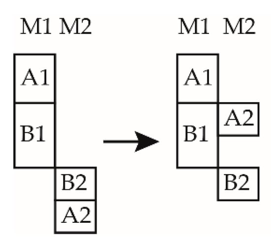
Figure 1.
Demonstration of compact scheduling.
The proposed algorithm can be given as follows:
In stage 1, the upward weights are calculated as
Communication delay, i.e., the average of the execution time of in all the machines at the same layer of ki, has been incorporated into Pki,j. ks denotes the direct successor of ki. Pki,j denotes the processing time of ki in the shared resource Mj; Rankp denotes the upward rank. If the node is at the final level, , NumMac (ki) denotes the shared resource in the same layer as node ki. The average execution time of all the previous tasks is related to the shared resource NumMac (ki) at that layer.
Stage 2 involves the selection of tasks with the highest Rankp in the list. According to the maximum completion time of all the scheduled predecessor tasks, the available slots are searched, and the location of the shared resource Mj with the earliest time slots is allocated to the available (Mj) task nodes.
In stage 3, after completing all the scheduled tasks in stage 1 and 2, the time slots among the scheduled resources are researched according to each shared resource, as denoted in Equation (6).
Mj_PPA ∈ {Mj, AFT(ks) − AST(kf) > sum(Pki, j)}, ks,kf,ki ∈ shed(Mj)
If a shared resource Mj_PPA has a time slot in the scheduled task, we can find the maximum actual completion time of their predecessor tasks (PAFT) for tasks arranged by the previous DAG, as denoted in Equation (7); next, we calculate the PPA table and reschedule Mj_PPA accordingly.
PAFT(ki) = max[AFT(ks)], ks ∈ Pred(ki)
2.3. Example Demonstration
The three DAGs and their node constraints are depicted in Figure 2; the dashed arrow denotes the start time of the tasks. A1–A6 belong to G1 (DAG A), B1–B6 belong to G2 (DAG B), C1–C6 belong to G3 (DAG C), and M1–M5 denote a set of shared resources. The hierarchy of the shared resources and task nodes can also be observed. The priority constraints between the tasks in each DAG are represented by the solid arrowhead lines. For example, the successor tasks of A1 are A4, and the successor tasks of C3 are C4. The specific functional constraints (layering) and the task layering of all the shared resources are also depicted in Figure 2, i.e., A1, A2, B1, B2, and C1. C1 can be executed by the shared resources M1, M2, and M3, which belong to Layer 1, or by other layers.

Figure 2.
Hierarchical diagram of the multi-DAG task nodes and shared resources.
Table 2 is a hierarchical table of shared resources presenting the serial number of shared resources and their corresponding layers. Table 3 presents the data length of each task node, which can be calculated using Equation (1) to obtain the execution time Pki,j. Table 4 presents SDj and Cj of the shared resources. Table 5 denotes the STki values. For a start node kistart = {ki, Pred(ki) = ∅} without predecessor tasks, there exists a corresponding start time. Table 6, Table 7 and Table 8 denote that after calculating the processing time (Pki,j), all the corresponding “-” lines indicate that node ki cannot be executed on the shared resource Mj. Therefore, the specific functional constraints (hierarchical relations) can also be observed from these tables.

Table 2.
Shared resources of each layer.

Table 3.
Data length (Dki) of DAGs.

Table 4.
Speed (SDj) and delay (Cj) of the shared resources.

Table 5.
Start time (STki) for each DAG.

Table 6.
Processing time with priority relation (PR) in DAG A.

Table 7.
Processing time with priority relation (PR) in DAG B.

Table 8.
Processing time with priority relation (PR) in DAG C.
Figure 3a–c denotes the schematics of three scheduling algorithms: shortest processing time (SPT), round-robin (R-R), and HEFT. No constraint connection is depicted on the graph for clarity. The constraint relation between the tasks is shown on the edges of Figure 2.
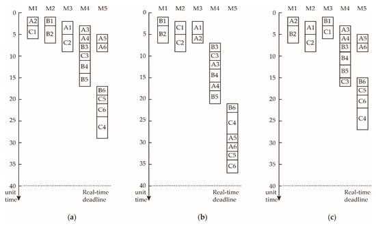
Figure 3.
Scheduling examples of three different scheduling algorithms: (a) SPT; (b) round-robin; and (c) heterogeneous earliest finish time (HEFT).
The SPT algorithm sorts all the DAG tasks on the layer from small to large according to the processing time; further, the algorithm schedules the tasks according to the earliest time slot of the shared resources that they possess until all the task nodes in all the layers complete task scheduling.
The R-R algorithm can be used to schedule the tasks in the DAG according to the serial number of the DAG and to allocate tasks to the earliest time slot of shared resources in the corresponding layer.
The associated communication time Cks,ki = 0. In addition, for the end node, Rankp can be calculated using Equation (8), whereas, for other nodes, Rankp can be calculated using Equation (5).
Here, NumMac (Mj) denotes the number of matching shared resources, i.e., Layer (j) = Layer (ki).
Table 9 presents the PPA table, and Figure 4 depicts the adjustment method using a PPA table diagram. The graph shown herein reveals that the HPEFT algorithm is arranged according to Rankp (ki); B5 is scheduled next to B6, subsequently followed by C5, C6, and C4. However, this approach is not optimal. According to the algorithm proposed in the previous section, C5, C6, and C4 are not directly connected with C3 scheduling. Hence, there is a time slot between A6 and B6. Therefore, according to Equation (6), all node tasks in the shared resource M5 can evaluate their PPA table according to the tasks that were scheduled in M5 in the previous stage with respect to the PPA table presented in Table 9.

Table 9.
The predecessor pointer adjustment (PPA) table.
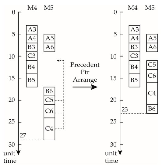
Figure 4.
Predecessor pointer adjustment (PPA).
As depicted in Figure 4, the first step is to arrange A5 and A6 at time 5 and 7; schedule C5, C6, and C4 at time 11; and finally schedule B6 to C4, which can reduce the makespan from 27 to 23.
2.4. Description of the HPEFT Algorithm
| Algorithm 1 HPEFT |
| Input: DAG group , resource group , processing time matrix of tasks in a shared resource set , DAG deadline, constraint matrix , and start time matrix Output: Scheduling List HPEFT () 1. Unscheduled DAG list unscheTasks←Tki (k = 1,2…K, i = 1, 2…Nk) 2. Calculate Rankp of each Tki in unscheTasks, and arrange them in the ascending order 3. Using Equation (1), the data length Di, shared resource speed SDj, and delay Cj are substituted, and the processing time matrix P is obtained. 4. For l = 1, 2…L 5. Find whether all the tasks performed at this unscheLayerTasks←{Tki, Layer(ki) ∈ l} in unschTasks. 6. WHILE (unscheLayerTasks ≠ ∅) 7. Sort all the tasks Tki in unscheLayerTasks according to Rankp (Tki), and find the current minimum Tki as Tki_urgent. 8. Using Equation (3), find an EST (Tki,Mj) suitable for scheduling. 9. Assign Tki_urgent to the Scheduling List HPEFT (). 10. Delete the Tki_urgent Task from unscheLayerTasks. 11. END WHILE 12. END FOR 13. Find the idle time slot in the Mj Gantt chart using Equation (6). 14. If Mj has an idle time slot, all the tasks scheduled to Mj should be returned to rearrange(j)←{Tki, Tki ∈ Shed (Mj)}; then, clear the Mj scheduling table, i.e., the scheduling list. 15. According to their predecessor AFT, calculate the corresponding PAFT(ki) in the ascending order for the PPA table. 16. WHILE (rearrange(j) ≠ ∅) 17. Schedule the minimum PAFT(ki) of task, Tki_rearrange_urgent, in the PPA table to Mj ∈ Tavailable(Mj) in the scheduling list; if overlay exists, postpone the other tasks for Tki_rearrange_urgent. 18. Delete Tki_rearrange_urgent. 19. END WHILE 20. Makespan is calculated using Equation (2), RITS is calculated using Equation (9), and RLBD is calculated using Equation (10). 21. Return the scheduling list End Procedure |
The HPEFT flowchart is depicted in Figure 5.
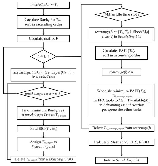
Figure 5.
Flowchart of HPEFT.
2.5. Time Complexity
Assuming that each DAG has N nodes and that the number of computing resources is Q, the worst-case time complexity of the HEFT algorithm is computed to be O(N2Q) [2]. If there are K such DAGs that need to be simultaneously scheduled, the time complexity of HPEFT becomes O(K2N2Q). HPEFT needs to adjust the order of scheduling in shared resource with time slots and obey the compact scheduling rule because it can find all the time slots and sort PPA table in stage 3. The order of time complexity increases the algorithm’s complexity; therefore, the complexity of the algorithm is O(K2N2Q2).
3. Experimental Result and Analysis
3.1. Parameter Setting and Test Data Generation
The main parameters of the test sample data are the total number of tasks Nk, the number of layers L, task range TR, the total number of shared resources Q, number of DAGs k, uniform deadline time and start time STki, shared resource speed SDj, and delay Cj.
The tasks and their hierarchical generation are as follows: select k-th DAG tasks and randomly distribute them in each layer. At least one task node is required in each layer, and the task number is distributed from the top to the bottom in an orderly manner. Further, the next DAG can be selected until all the DAGs have completed the tasks and the allocation of layers. The shared resource hierarchy is generated as follows; select all the shared resources Q; then, randomly allocate these shared resources to L layers, with each layer having at least one shared resource from top to bottom according to the serial number from small to large. Further, the start time STki and execution time Pki,j are generated as follows; first, according to the task serial number, K × Nk, TR is randomly generated from [1, TR]; furthermore, the nodes without previous tasks also generate STki equally and randomly using the same task number, with a length of [1, 1.2 × TR]; finally, SDj is randomly and evenly generated according to the length in the range [1, 0.2 × TR]. Cj of the shared resources is generated according to the scope [1,2]. Pki,j of each task is calculated using Equation (1). The priority relation matrix PR (ku, kv) can be generated as follows; find all the tasks in layer L and layer L + 1. The number of tasks in these layers is recorded as Nk, l and Nk, l + 1. According to Nk, l and Nk, l + 1, construct a diagonal unit matrix with Nk, l as the number of rows and Nk + l, 1 as the number of columns. If the columns are not sufficient, duplicate until the elements of the matrix are filled. If Nk, l ≥ Nk + l, 1, randomly scramble the rows; if Nk, l < Nk + l, 1, randomly scramble the columns, and increase the row (column) element 1 with a probability of 0.1 to the rows; assign the matrix to the corresponding position of the priority relation constraint matrix PR as depicted in Figure 6. The diagonal unit matrix can be used to ensure that the upper and lower tasks have nodes connected to their proper edges and to prevent the generation of the isolated nodes. The row (column) elements are increased with a probability of 0.1 to ensure full coverage of the test set as far as possible. The test case data can be obtained after generating the test case.
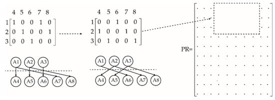
Figure 6.
Diagram of the test case generation process.
3.2. Definition of the Performance Evaluation Indices
3.2.1. Ratio of the Idle Time Slot (RITS)
RITS is obtained by dividing the total length of the scheduling node task in each shared resource according to the difference between the actual EST and the actual latest end time for all the tasks in the shared resource. After adding these times, the percentages of the ratios of the idle time slots, as shown in Equation (9), are subtracted from 1. Equation (9) denotes the mathematical definition of RITS.
with the presence of hierarchical limited resources, the rate of idle slots generated by the multi-DAG scheduling algorithm determines the percentage of time wasted by all the shared resources after applying scheduling. The larger this value, the more will be the wasted time because of the hierarchical arrangement of the shared resources.
3.2.2. Relative Laxity with Respect to the Deadline (RLD)
RLD denotes the sum of the differences between the maximum completion time and the deadlines for each shared resource, representing the overall scheduling performance while using all the shared resources. Equation (10) defines RLD, which indicates the number of time slot intervals between the maximum completion time and the specified deadline.
RLD = sum{Deadline − makespan (Mj)}, makespan(Mj) = max(AFT(ki))
subject to ki scheduling in Mj
subject to ki scheduling in Mj
3.3. Experimental Analysis
This section presents the performance of the algorithm using four experiments. The experimental settings are as follows. All the tasks ranged from 1 to 10 time units, with the deadline of time units being represented by (Number of tasks) × (Number of layers) × (Range of tasks). Other experimental parameters were set as presented in Table 10.

Table 10.
Test parameter setting.
Test 1 verifies the effect of the number of tasks on the algorithm. When the number of DAGs and the sharing of resources and layers are similar, heavier and increased number of tasks will result in better scheduling performance. As can be observed from Figure 7a, the makespan of each algorithm increases as the number of tasks increases. Among the algorithms considered herein, HPEFT exhibited the minimum makespan with increasing number of tasks; its advantage of the maximum completion time is considerably pronounced. Figure 7b depicts the RITS. HPEFT exhibited more compact scheduling compared with the other algorithms. SPT, HEFT, and HPEFT exhibited more idle slots with respect to the deadline. As can be observed from Figure 7c, the RLD of HPEFT increases as the number of tasks increased when compared with other algorithms, implying that the more the number of tasks, the better will be the scheduling performance for the same deadline. For the elapsed time of algorithm in test 1, although the HPEFT time increased when compared with that of other algorithms, the average increase in time is 1.9, 2.3, 1.1, and 1.4 times that of SPT, R-R, HEFT, and PEFT, respectively. For the maximum task condition in test 1, the number of tasks is 90 × 3 = 270, and the increase in time is 65 ms, as presented in Table 11.
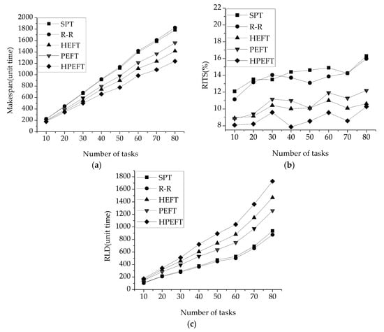
Figure 7.
Variable number of tasks: (a) makespan, (b) RITS, and (c) RLD.

Table 11.
Elapsed time of test 1.
Test 2 presents the effect of the number of shared resources on the algorithm. In the case of the same number of tasks and the same number of layers, the lower the number of shared resources, and the heavier the scheduling task will be. Figure 8a denotes the relation between the number of shared resources and makespan. It can be observed from the figure that the HPEFT algorithm exhibited smaller makespan than that exhibited by the other algorithms, and the lower the number of shared resources, the greater the advantage of HPEFT will be. Figure 8b shows that RLD increases with an increase in the number of shared resources, and HPEFT has a slight advantage over other algorithms. The greater the number of shared resources, the earlier the completion of each scheduled task; accordingly, more idle time slots with deadlines are observed. However, for RITS, the effect of HPEFT in test 2 is 0.14–1.22% more than that of HFET, and there is no obvious advantage.
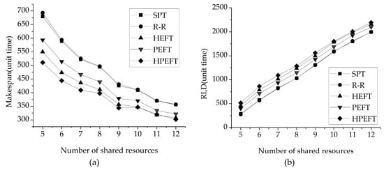
Figure 8.
Variable number of shared resources: (a) makespan and (b) RLD.
The number of DAGs is an important factor affecting the multi-DAG workflow scheduling. Figure 9a shows that HPEFT finishes execution in lesser time than that required by the other algorithms as the number of DAGs increases. As the number of tasks increases, this advantage will become obvious. Figure 9b shows that as the number of DAGs increases, the RITS of HPEFT has the minimum value, whereas the time slot utilization improves. Figure 9c shows that HPEFT has advantages with respect to RLD, and the greater the number of DAGs, the greater the advantage.
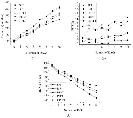
Figure 9.
Variable number of DAGs: (a) makespan, (b) RITS, and (c) RLD.
Test 3 also compared the algorithms in terms of the missed deadline rate (MDR). MDR is defined as the number of times that a deadline was missed when 100 randomly generated scheduling problems were solved. Table 12 presents the MDRs for the three most serious cases in test 3. The MDR was decreased by 13 to 30% using the HPEFT method, according to the data presented in the sixth column.

Table 12.
MDRs of test 3.
In test 4, the number of layers refers to the number of layers of the DAG and tasks. The higher is the number of layers, the longer the precedence relation. The interaction between multi-DAG and the layers increases the complexity of the problem and tests the scheduling performance of the algorithm.
Figure 10a denotes that HPEFT always has the smallest makespan. The higher the number of layers, the greater the advantages of HPEFT with respect to the makespan. Figure 10b shows that RLD has an advantage in HPEFT. The RITS of HPEFT is 0.327–1.722% larger than that of HEFT, and there is no obvious difference.
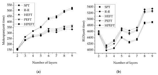
Figure 10.
Variable number of layers: (a) makespan and (b) RLD.
Test 5 was run to study the statistical characteristics of the HPEFT algorithm in terms of the makespan. Eighty tasks were scheduled in the test; the other parameters are the same as those in test 1, and 1000 calculations were run. Figure 11a is a boxplot of the makespan results. As can be observed from the figure, when compared with other algorithms, the upper and lower quartile of the results were lower than those of the other algorithms, and the interquartile range (IQR) was not considerably different. Figure 11b gives a 95% confidence interval (CI) plot. As depicted in the figure, the average result from the HPEFT is smaller than that obtained from other algorithms; however, the difference in the CI is also small.
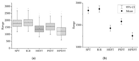
Figure 11.
Statistical plots: (a) box plot and (b) 95% CI plot.
Table 13 summarizes the indicators recorded from tests 1 to 4. The makespan decreases by 3.87 to 57.68%; RITS decreases by 0 to 6.53%; RLD increases by at least 2.27 to 8.58% because of the different deadlines; and the elapsed time increases by 42.14 to 63.62%. Although the elapsed time increases, we can observe from Table 11 that the difference in computing time is acceptable.

Table 13.
Percentage differences between various indicators and their worst values.
4. Optimization of the Signal Processing Scheduling Process for a Multigroup Scan UPA System Based on HPEFT
Figure 12 depicts the architecture of a multigroup scan UPA system using the TFM method [24]. After the acquisition, multigroup scan ultrasound signals are sent to the on-chip memories (OCMs) of the FPGA chip. The shared signal processing modules, such as Hilbert transform and FIR noise reduction, are connected to the Avalon-MM bus of the system. The scheduling control module reads the signals by writing the OCMs in the control and status register and interrupt request (IRQ) control chips, and the signals are sent to the corresponding signal processing module with respect to the DAG tasks. After completing DAG processing, the signal is sent to the DDR3 buffer controlled by the DDR controller from which signals are sent directly to a PCI-E bus controller using the Scatter–Gather DMA through the Avalon-ST bus. The PCI-E controller receives the signal of the Scatter–Gather DMA. After all DAG tasks are processed, all signals are sent to the PC through the PCI-E PHY physical terminal.
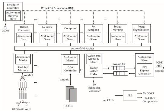
Figure 12.
Architecture of the multigroup-scan ultrasound TFM system.
A virtual example of multiple DAG scheduling for a multigroup-scan UPA system is depicted in Figure 13.
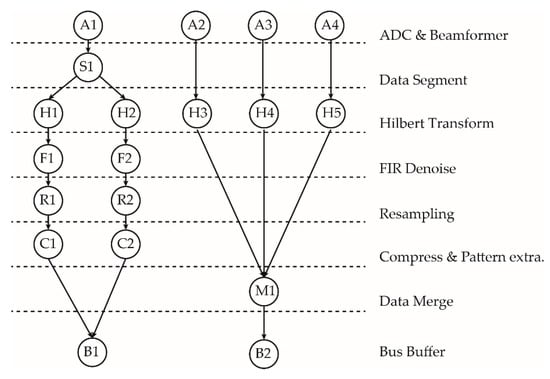
Figure 13.
An example of two DAG scans.
The first DAG is the graph formed after a set of piezoelectric chips acquires the segment data and then applies the focusing delays, the Hilbert transform, FIR denoising, resampling, compression & pattern extraction and data merge. Further, the data is sent to the bus buffer. The second DAG expresses the functions obtained when the signals collected by the three sets of piezoelectric wafers are subjected to focusing delays; only then is the Hilbert transform performed along with data merging, and the data are finally sent to the bus buffer.
To simplify the experiment, the process modules in a single layer (performing the same special function) are considered to be homogeneous, and the ADC and beam-forming steps are considered to be the start time of DAG. Table 14 denotes the processing time of the signal processing modules, Table 15 presents the number of signal processing modules used to facilitate the calculation in the FPGA by considering k = 1024. The time unit is a single clock cycle in the FPGA and is 10 ns (100 MHz) in these experiments.

Table 14.
Processing time required for performing tasks.

Table 15.
Number of signal processing modules.
Figure 14 provides a Gantt chart of the whole system as scheduled by HPEFT. In this figure, we can observe the effect of hierarchical scheduling to address the functional constraints.
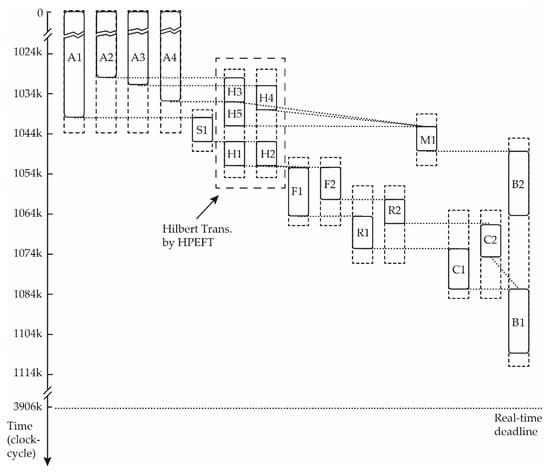
Figure 14.
Gantt chart after scheduling multiple groups of scanning tasks by HPEFT.
To clearly denote the effect of scheduling, we selected the Hilbert transform as part of the overall system scheduling to verify the results of the algorithm after the simulation of the FPGA scheduler. We used Hilbert transform tasks H1–H5 to illustrate the scheduling situation and generate the simulation results from Modelsim 10.2 SE (Mentor Co., Ltd., Wilsonville, OR, USA). In this case, two DAGs arrive at the Hilbert transform tasks H1–H5 after handling tasks A1, A2, A3, A4, and S1. Tasks H1–H5 are ranked as in Table 16 by the HEFT algorithm; therefore, the scheduling order of the HEFT algorithm is H1, H2, H3, H4, H5, and the simulation results are presented in Figure 15a. The PPA table obtained by the HPEFT algorithm is depicted in Table 17. The scheduling orders are H3, H5, H1 in Hilbert Transform module 1 and H4, H2 in Hilbert Transform module 2. The simulation results are denoted in Figure 15b.

Table 16.
Task Rankp of tasks in Hilbert transforms.
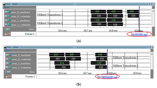
Figure 15.
Hilbert transform scheduling simulation in ModelSim: (a) HEFT and (b) HPEFT.

Table 17.
PPA table for tasks in Hilbert transforms.
The experimental parameters are set as follows: the processing times of all the tasks (H1-H5) Pki,j are 6k clock cycles, and the Hilbert transform shared resources number is two. There are four scanning groups; each group has 32 elements with 16k sample depth; therefore, all the ADC & beam-forming times are 1024k clock cycles [25]. As depicted in Figure 15a,b, the completion time of all the schedules using HPEFT is approximately 10.78 ms, whereas that of the schedules employing HEFT is 10.90 ms. If 1 ms is given to the remaining signal processing modules, the frame periods, as shown in Figure 15a,b, will be 11.90 ms and 11.78 ms, respectively. Therefore, using the HPEFT algorithm, the frame period was increased by 1% in this experiment. If ADC and beam-forming require less time, the increase in frame period will be made obvious by scheduling.
In our experiment verification environment, Figure 16 shows the experiment circuit board and Signaltap II (Intel Corporation, Santa Clara, CA., USA) diagram with the small-scale local experiment.
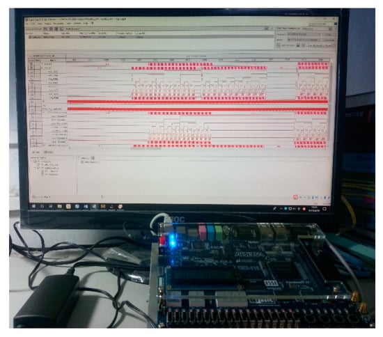
Figure 16.
Experiment circuit board and Signaltap II diagram.
5. Conclusions
Based on the existing multi-DAG resource scheduling algorithms, this study proposes a deadline, constraint, multi-DAG, sharing-limited HHDMP scheduling problem and proposes an HPEFT algorithm for solving it. This algorithm inherits the advantages of both the HEFT algorithms for calculating the upward rank for critical paths, and it is improved for performing hierarchical tasks and for obtaining shared resources. Based on the characteristics of the hierarchical resources, wherein the DAG predecessors and successors must be compact, a stage 3 PPA algorithm was proposed. After stage 1 and 2 scheduling, PPA can find a large time slot to make the same DAG task of the same shared resource schedule compact, shortening the time of the multi-layer resource scheduling problem. This study also adopted two indicators with respect to the hierarchical scheduling problem: RITS and RLD. When compared with several classical algorithms, such as SPT, R-R, HEFT, and PEFT, the experimental results denote that the makespan of the proposed algorithm was reduced by 5 to 16%, RITS was reduced by 0 to 6.53%, RLD was increased by 2.27 to 8.58%, and MDR was decreased by 13 to 58%. Even so, the algorithm still exhibits some limitations. First, when the number of shared resources and layers increases, the RITS index of the HPEFT algorithm shows no clear advantage over that of HEFT. Second, the time complexity is increased, and the computing time increases by approximately 50%. Third, in the experiments that were not presented above, the PPA method can significantly increase the scheduling imbalance between DAGs. An example of a multigroup scanning UPA system based on the Altera Qsys architecture was also presented, and the HPEFT algorithm scheduling was verified in this architecture by scheduling the Hilbert transform tasks in two DAGs.
In future works, we intend to focus on selecting the initial resources for the algorithm with respect to different types of ultrasound scanning; the relation between the shared resources in each layer and the successors, predecessors, and number of tasks in the layer, and studying the layer delay of shared resources. More complex and numerous signal processing modules based on FPGA will have to be tested in the future to verify the effectiveness of the scheduling algorithms discussed in this study.
Author Contributions
Y.L., W.T., and G.L. conceived the concept of the study; Y.L. performed the experiments; Y.L. and W.T. designed the system model; and Y.L. wrote the study.
Funding
This work was financially supported by the National Key Foundation for Exploring Scientific Instrument (2013YQ230575) and Guangzhou Science and Technology Plan Project (201509010008).
Acknowledgments
We thank Guangzhou Doppler Electronic Technology Co., Ltd. (www.cndoppler.cn) for technical support.
Conflicts of Interest
The authors declare no conflicts of interest.
References
- Byun, E.J.; Choi, S.J.; Baik, M.S.; Gil, J.; Park, C.; Hwang, C. MJSA: Markov job scheduler based on availability in desktop grid computing environment. Future Gener. Comput. Syst. 2007, 23, 616–622. [Google Scholar] [CrossRef]
- Topcuouglu, H.; Hariri, S.; Wu, M.Y. Performance-effective and low-complexity task scheduling for heterogeneous computing. IEEE Trans. Parallel Distrib. Syst. 2002, 13, 260–274. [Google Scholar] [CrossRef]
- Ullman, J.D. NP-complete scheduling problems. J. Comput. Syst. Sci. 1975, 10, 384–393. [Google Scholar] [CrossRef]
- Arabnejad, H. List Based Task Scheduling Algorithms on Heterogeneous Systems—An Overview. Available online: https://paginas.fe.up.pt/~prodei/dsie12/papers/paper_30.pdf (accessed on 5 June 2013).
- Sakellariou, R.; Zhao, H. A hybrid heuristic for DAG scheduling on heterogeneous systems. In Proceedings of the 18th International Parallel and Distributed Processing Symposium, Santa Fe, NM, USA, 26–30 April 2004; p. 111. [Google Scholar]
- Hagras, T.; Janecek, J. A simple scheduling heuristic for heterogeneous computing environments. In Proceedings of the Second International Conference on Parallel and Distributed Computing, Ljubljana, Slovenia, 13–14 October 2003; IEEE Computer Society: Washington, DC, USA, 2003; pp. 104–110. [Google Scholar]
- Ilavarasan, E.; Thambidurai, P.; Mahilmannan, R. High performance task scheduling algorithm for heterogeneous computing system. In International Conference on Algorithms and Architectures for Parallel Processing; Springer: Berlin/Heidelberg, Germany, 2005; pp. 193–203. [Google Scholar]
- Ilavarasan, E.; Thambidurai, P.; Mahilmannan, R. Performance effective task scheduling algorithm for heterogeneous computing system. J. Comput. Sci. 2007, 3, 28–38. [Google Scholar]
- Bittencourt, L.F.; Sakellariou, R.; Madeira, E.R.M. DAG scheduling using a lookahead variant of the heterogeneous earliest finish time algorithm. In Proceedings of the 18th Euromicro International Conference on Parallel, Distributed and Network-Based Processing, Pisa, Italy, 17–19 February 2010; IEEE: Piscataway, NJ, USA, 2010; pp. 27–34. [Google Scholar]
- Honig, U.; Schiffmann, W. A meta-algorithm for scheduling multiple DAGs in homogeneous system environments. In Proceedings of the eighteenth IASTED International Conference on Parallel and Distributed Computing and Systems, Dallas, TX, USA, 16–18 November 2006. [Google Scholar]
- Zhao, H.; Sakellariou, R. Scheduling multiple DAGs onto heterogeneous systems. In Proceedings of the 20th IEEE International Parallel & Distributed Processing Symposium, Rhodes Island, Greece, 25–29 April 2006; p. 14. [Google Scholar]
- Yu, Z.; Shi, W. A planner-guided scheduling strategy for multiple workflow applications. In Proceedings of the 2008 International Conference on Parallel Processing, Portland, OR, USA, 8–12 September 2018; pp. 1–8. [Google Scholar]
- Baker, T.P. An analysis of EDF schedulability on a multiprocessor. IEEE Trans. Parallel Distrib. Syst. 2005, 16, 760–768. [Google Scholar] [CrossRef]
- Stavrinides, G.L.; Karatza, H.D. Scheduling multiple task graphs with end-to-end deadlines in distributed real-time systems utilizing imprecise computations. J. Syst. Softw. 2010, 83, 1004–1014. [Google Scholar] [CrossRef]
- Tian, G.; Xiao, C.; Xie, J. Scheduling and fair cost-optimizing methods for concurrent multiple DAGs with deadline sharing resources. Chin. J. Comput. 2014, 37, 1607–1619. [Google Scholar]
- Tian, G. Research several problems of scheduling multiple DAGs sharing resources. Ph.D. Thesis, Beijing University of Technology, Beijing, China, 2014. [Google Scholar]
- Xu, X.; Xiao, C.; Tian, G.; Sun, T. Expansion slot backfill scheduling for concurrent workflows with deadline on heterogeneous resources. Clust. Comput. 2017, 20, 471–483. [Google Scholar] [CrossRef]
- Tang, W.; Liu, G.; Li, Y.; Tan, D. An Improved Scheduling Algorithm for Data Transmission in Ultrasonic Phased Arrays with Multigroup Ultrasonic Sensors. Sensors 2017, 17, 2355. [Google Scholar] [CrossRef] [PubMed]
- Li, Y.; Tang, W.; Liu, G. Improved scheduling algorithmfor signal processing in asynchronous distributed ultrasonic total-focusing method system. PLoS ONE 2019, 14, 906. [Google Scholar]
- Anwar, N.; Deng, H. A Hybrid Metaheuristic for Multi-Objective Scientific Workflow Scheduling in a Cloud Environment. Appl. Sci. 2018, 8, 538. [Google Scholar] [CrossRef]
- Miao, G.; Li, G.; Li, T.; Liu, Y. H∞ Consensus Control for Heterogeneous Multi-Agent via Output under Markov Switching Topologies. Electronics 2018, 7, 453. [Google Scholar] [CrossRef]
- Drozdov, A.Y.; Tchernykh, A.; Novikov, S.V.; Vladislavlev, V.E.; Rivera-Rodriguez, R. PHEFT: Pessimistic Image Processing Workflow Scheduling for DSP Clusters. Algorithms 2018, 11, 76. [Google Scholar] [CrossRef]
- Feng, S.; Fu, P.; Zheng, W. A Hierarchical Multi-Label Classification Algorithm for Gene Function Prediction. Algorithms 2017, 10, 138. [Google Scholar] [CrossRef]
- Holmes, C.; Drinkwater, B.W.; Wilcox, P.D. Post-processing of the full matrix of ultrasonic transmit-receive array data for non-destructive evaluation. NDT E Int. 2005, 38, 701–711. [Google Scholar] [CrossRef]
- Li, Y.; Tang, W.; Liu, G. Improved bound fit algorithm for fine delay scheduling in a multigroup scan of ultrasonic phased arrays. Sensors 2019, 19, 906. [Google Scholar] [CrossRef] [PubMed]
© 2019 by the authors. Licensee MDPI, Basel, Switzerland. This article is an open access article distributed under the terms and conditions of the Creative Commons Attribution (CC BY) license (http://creativecommons.org/licenses/by/4.0/).