Abstract
In this paper, we proposed a novel D-shaped microstructure fiber sensor based on lossy mode resonance (LMR). TiO2/HfO2 bilayer film is coated on the exposed-core portion of photonic crystal fiber (PCF) as a sensing channel. The asymmetrical LMR region generates strong birefringence, which leads to the separation of X polarization and Y polarization. This structure excites a stronger evanescent field than the conventional D-shaped fiber, thereby greatly improving the sensor sensitivity. Additionally, the metallic oxide bilayer can further enhance the sensor’s performance. We numerically investigated the influence of the number of air holes removed in PCF on the sensor performance and the proportion of TiO2 to HfO2 in theory for the first time. The results show that an ultra-high sensitivity of 140,000 nm/RIU is obtained, which is an order of magnitude higher than that of surface plasmon resonance sensors with a similar waveguide structure and LMR sensor coated film. This achievement means that LMR-based sensing systems are more sensitive than many sensors in real-time and distributed measurements, which will play an extremely important guiding role in the structural design of microstructure fiber sensors in the future.
1. Introduction
The optical waveguides based on nanofilm coatings have been widely investigated over the past decades [1]. The latest achievement of nanoscale new materials and coating methods has brought new vitality to the field [2]. The combination of thin film coating and fiber optic devices enhances sensing characteristics and adds novel functions [3]. Depending on the properties of the coating layer, it is mainly divided into the following three cases [4]. The first case is called surface plasmon resonance (SPR), which is generated by some metals with negative permittivity [5]. The resonance will occur at the maximum coupling between waveguide modes and surface plasmons polariton modes (SPP modes). The second phenomenon is known as lossy mode resonance (LMR), which is generated by lossy dielectrics with positive permittivity and a higher refractive index than both waveguides and surrounding medias. The third is called long-range surface exciton polariton (LRSEP), which is generated by the dielectrics, whose permittivity is with near-zero real part and large imaginary part [6]. This case is beyond the category of this research and will not be mentioned further. Therefore, this research will pay attention to the SPR and LMR.
LMR-based optical fiber sensors have become a research hotspot in the past few years [5,6]. As a novel sensor, LMR-based sensors have been researched in the sensing field of physics, chemistry, and biology from 2010, which opened a new direction for the sensors based on electromagnetic resonance phenomenon. Compared to SPR sensors, LMR sensors have many excellent performance features. One of the advantages of the LMR sensor is that it can be excited by both transverse electric (TE) and transverse magnetic (TM) polarization modes [7], while SPR occurs only by TM polarized light, which limits the type of light source. The flexibility of the utilization of film materials and numerous fabrication techniques, unlike SPR based devices, is another important advantage of the fabrication of LMR optical fiber sensors. LMR effects can be produced by semiconductor and polymer films such as tin oxide (ITO), titanium dioxide (TiO2), zinc oxide (ZnO), and poly (allylamine hydrochloride) (PAH)/poly (styrene sulfonate) (PSS). In addition, methods of manufacturing techniques include magnetron sputtering and layer-by-layer. Furthermore, the sensitivity of the LMR sensor is significantly higher than that of the SPR sensor in the optical waveguide of the similar structure. One proposed SPR-based refractive index (RI) sensor based on a tapered fiber [8] has a sensitivity of 2278.4 nm/RIU. In similar waveguide conditions, the sensitivity of the LMR-based sensor can reach 6008 nm/RIU [9].
In comparison to traditional fiber structures, the photonic crystal fiber (PCF) has various geometric structures that can be flexibly designed for greater sensing performance [10,11,12]. Sensing film and analyte can be inserted into air holes to enable the preparation of an SPR sensor or an LSPR sensor. However, too-small air holes make it difficult for analytes to fill evenly and quickly, which is hard to apply in RI sensing fields. In recent years, a lot of literature has put forward many different microstructure optical fibers [13], which provide a larger percentage of the evanescent field relative to conventional fibers and can be used for the interaction with analytes. Recently, Luan et al. have simulated an SPR sensor based on D-shaped all-solid hollow core photonic crystal fiber whose sensitivity can reach 2900 nm/RIU. However, the air holes in all-solid PCF are small and are easily damaged during processing [14].
In this paper, we propose a novel D-shaped microstructure fiber sensor based on LMR. This structure excites a strong evanescent field, thereby greatly improving the sensitivity of the sensor. In addition, we investigated the influence of the number of pores removed in PCF on the sensor performance and the proportion of TiO2 to HfO2 in theory. A wide range of analyte RI from 1.330 to 1.395 is numerically calculated to detect the sensing performance. This paper plays a significant role in the structural design of microstructure fiber sensors.
2. Sensor Structure and Theoretical Modelling
To solve the difficulty of coating a film on the air hole wall in PCF, a novel D-shaped microstructure fiber sensor is proposed. The schematic diagram of the proposed fiber sensor based on LMR is shown in Figure 1. The fiber core diameter is d = 15 μm. The air hole diameter and the thickness of the outer wall of air holes are 50 μm and 10 μm, respectively. The distance of adjacent air holes is c = 2 μm. The outer wall of air holes could be removed through chemical etching with hydrofluoric acid (HF) [15]. Additionally, we can use micromachining techniques to get a smooth exposed-core region of PCF [16]. Coating of the metal layers can be performed with a chemical vapor deposition technique [17] or a wet chemistry deposition technique [18]. The expose-core fiber sensors can significantly improve measurement response time. Moreover, the polished side is smoother than PCF exposing one or two air holes, so it is easy to plate TiO2/HfO2 film. Plating TiO2/HfO2 film can be prepared by both magnetron sputtering deposition and chemical vapor deposition, which is much easier to implement than coating a film on the air hole wall of PCF.
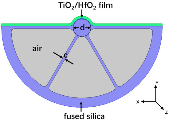
Figure 1.
Schematic of a novel microstructure fiber sensor based on lossy mode resonance.
We utilized Finite Element Method (FEM) by COMSOL Multiphysics for the investigation of electromagnetic field distribution in designed sensor. The number of triangle mesh elements are 24,390 and the number of boundary elements are 2189. The boundary condition is set to the perfectly matched layer (PML). The material of the D-shaped microstructure fiber is fused silica and its dispersion characteristic is determined by the Sellmeier equation [19]
where a1 = 0.696166300, a2 = 0.407942600, a3 = 0.897479400, b1 = 4.67914826 × 10⁻³ μm2, b2 = 1.35120631 × 10⁻² μm2, and b3 = 97.9340025 μm2.
The TiO2 permittivity is determined by Lorentz model [4]
where is the high frequency dielectric constant, Ak is the amplitude, Bk is the center energy, and E is the photon energy. A single oscillator model was used for the simplicity and the best fit parameters for the theoretical simulations were: = 1, Bk = 1.2 eV, Ak = 101 eV2 and Ek = 6.2 eV.
Dispersion characteristic of HfO2 permittivity is described by the Lorentz oscillator model, which can be expressed as [20]
For simplicity, where j = 1, A = 1.956, B = 6.73 × 10⁻¹⁰ cm2, vp1 = 247 cm−1, v1 = 187 cm−1, = 216 cm−1, v = 1/.
For reference, the confinement loss of optical fiber sensor is defined as [21]
where k0 = 2π/λ is the wavenumber and Im (neff) is the imaginary part of the mode effective index.
The wavelength sensitivity is defined as
where is the peak wavelength and is the variation of analyte RI.
3. Results and Discussion
In Figure 2, the variation of the real part and imaginary part of effective mode refractive index is shown when analytes RI = 1.33. It is obvious that the core modes exhibit strong birefringence because of the asymmetrical LMR region. One of the modes is polarized substantially parallel to the axis of symmetry, while the other mode is orthogonal thereto. They are defined as y-polarization mode and x-polarization mode, respectively. It is notable that the real part of the core mode closer to the phase matching undergoes a rapid change. Figure 3 shows that the energy in the core mode is transferred to lossy mode in TiO2/HfO2 film when the phase matching is satisfied at a certain wavelength, so that resonant peaks are observed at this wavelength. In addition, each polarized mode excites multiple LMRs. Since the first LMR peak is considered to be the most sensitive, the sensitivity of the presented sensor is determined by considering only the first LMR peak (Figure 4) [20].
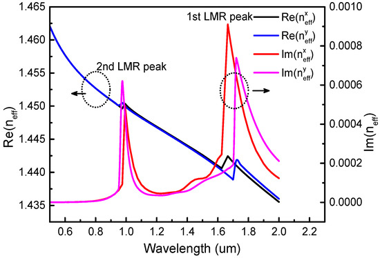
Figure 2.
Dispersion relations of effective index of core mode at analyte refractive index (RI) na = 1.33.
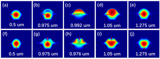
Figure 3.
Electric field distributions of core modes of (a–e) X-polarization at analyte RI na = 1.33 (f–j) Y-polarization at analyte RI na = 1.33.
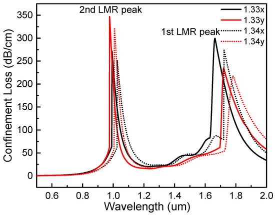
Figure 4.
Loss spectra of x-polarized and y-polarized peaks at analyte RI na from 1.33 to 1.34.
The variation of analyte RI will lead to changes of the phase matching condition between the core mode and the lossy mode, producing different loss spectra. Therefore, the variation of analyte RI can be detected efficiently by measuring the shift of the lossy peak wavelength.
As shown in Figure 2 and Figure 4, it is obvious that the full width at half maximum of x-polarization and y- polarization are almost equal, but the y-polarized resonance peak shifts greater than the x-polarized resonance peak. Therefore, only the y-polarized peak is considered because it is more suitable for analyte detection.
The exposed-core area in microstructure fiber, film thickness, and the proportion of TiO2 to HfO2 have a great influence on the performance of the sensor. From the reference, the sensor sensitivity increases with the increase of film thickness [22]. As the thickness of the TiO2 film increases, not only the intensity of resonances peak increase, but the position of the LMR peak shifts to longer wavelengths because the phase matching condition shifts to longer wavelengths. As a result of the mode coupling between lossy mode of the TiO2 film and core mode, we can obtain the maximum attenuation of light propagating through the optical waveguide. Therefore, this section will mainly discuss the influence of the number of air holes removed in PCF and the proportion of TiO2 to HfO2 thickness on sensor performance.
As shown in Figure 5, keeping the thickness of TiO2 film and analyte RI constant, when the number of removed air holes changes, that is, when the area of the exposed core changes, the depth and position of the absorption peak in the loss spectrum will change. Moreover, the number of air holes removed will affect the sensitivity of the sensor. Since the first LMR peak is the most sensitive to the variation of analyte RI, the sensitivity of the first resonant peak of the proposed sensor is considered. The sensitivity of x-polarized and y-polarized peak of PCF sensors with one air hole removed are 5100 nm/RIU and 5600 nm/RIU, respectively. The sensitivity of x-polarized and y-polarized peak of the sensors with two air holes removed are 4800 nm/RIU and 4900 nm/RIU, respectively. The sensitivity of x-polarized and y-polarized of D-shape microstructure (three air holes removed) fiber sensor are 5800 nm/RIU and 6400 nm/RIU at na RI from 1.33 to 1.34, respectively. These results show that the D-shaped microstructure fiber we proposed can excite a stronger evanescent field interacting with surrounding materials than conventional D-shape fiber.
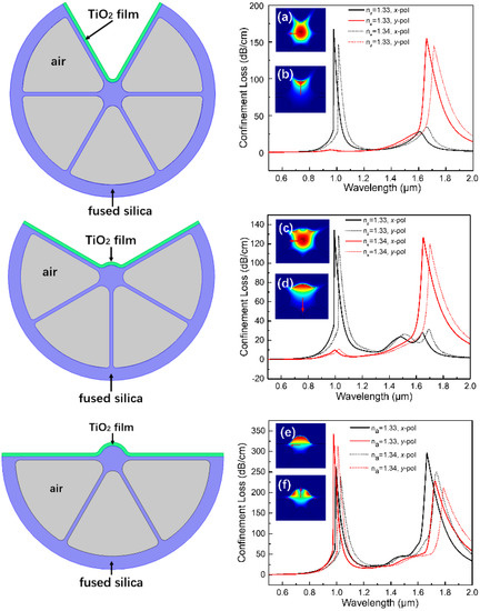
Figure 5.
Loss spectra of the photonic crystal fiber (PCF) with one, two, and three air holes removed at analyte RI na = 1.33, 1.34, respectively. (a–f) are the electric field distribution of the corresponding optical waveguide structures, respectively.
The sensor performance is affected by the proportion of TiO2 film to HfO2 film. As shown in Table 1, we compared the sensor coated by single TiO2 film with the sensor coated by TiO2/HfO2 bilayer film. An additional HfO2 layer covered on TiO2 has a higher dielectric constant, which can be regarded as a suitable material to enhance the proposed sensor’s sensitivity [20]. The simulated result shows that when the proportion of TiO2 to HfO2 is 80 nm/20 nm, the sensor has a better performance. This can be explained by the theory that despite HfO2 having a higher real part of permittivity, the imaginary part of its permittivity is zero. Therefore, the LMR effect cannot be excited alone by single HfO2. Therefore, when the proportion of HfO2 is high, the thickness of TiO2 becomes thin, so the sensitivity of the sensor is gradually reduced.

Table 1.
Sensitivity comparison of the proposed sensor coated by metallic oxide bilayer with sensor coated by single TiO2 layer.
In order to investigate the sensor performance, the range of analyte RI between 1.33 and 1.395 is numerically calculated. Figure 6 shows a comparison of the sensitivity of the sensor designed in this paper and two common microstructure fiber SPR and LMR sensors. The red line, the blue line, and the black line, respectively, shows the sensitivity of the sensor designed in this paper, the D-shaped LMR sensor, and SPR sensor based on microstructure fiber, which remove two air holes in the grapefruit PCF. The SPR sensor’s sensitivity in this literature can reach 13,500 nm/RIU [23]. In contrast, the wavelength sensitivities of the proposed sensor vary from 6700 nm/RIU to 62,500 nm/RIU when na increases from 1.33 to 1.39. The sensitivity of the designed sensor can reach maximum, 140,000 nm/RIU, at analyte RI na = 1.395, which is an order of magnitude higher than that of the SPR sensors and LMR sensors of the D-shaped fiber [24]. Theoretically, when the propagation constant of core mode and that of lossy mode are equal, phase matching condition is satisfied. In other words, the closer the effective RI of the two modes are, the higher the sensitivity of the sensor is.
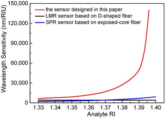
Figure 6.
A wavelength sensitivity contrast of the sensor designed in this paper, common D-shaped fiber lossy mode resonance (LMR)-based sensor [24] and exposed-core PCF surface plasmon resonance (SPR)-based sensor [23].
4. Conclusions
We propose a novel microstructure fiber sensor based on LMR. TiO2 film is coated onto exposed-core portion of PCF as a sensing channel. In addition, the effect of the exposed-core area (the number of air holes removed) of the PCF on the sensor performance is numerically investigated in theory, which plays an important guiding role in the micromachining of photonic crystal fibers in the future. The D-shape structure not only solves the difficulty in uniformly coating the film on the fiber, but also excites a stronger evanescent field than conventional D-shaped fiber, thereby greatly improving the sensor sensitivity. We also discuss the influence of TiO2 film thickness on proposed sensor performance. Since the sensitivity of the LMR sensor is related to the refractive index and thickness of the film, this paper compared the common D-shaped fiber sensor and the proposed novel D-shaped fiber sensor based on LMR coated with the same material (TiO2). The results show that an ultra-high sensitivity, 140,000 nm/RIU, is obtained at analyte RI na = 1.395 in the sensing range of 1.33–1.395, which is one order of magnitude higher than that of SPR sensors and LMR sensors of the similar waveguide structure.
Thus, the sensor sensitivity of D-shaped microstructure based on LMR is much higher than the conventional fiber sensor, since it can excite a stronger evanescent field. In addition, the sensitivity of the LMR sensor is far superior to that of the SPR sensor of the same waveguide structure. The sensor proposed in this paper is more sensitive in high refractive index solutions than in low refractive index solutions, which means it is more suitable for measuring liquids with high RI such as biochemical liquid analytes.
Author Contributions
Methodology, formal analysis, investigation, and writing—original draft preparation, X.-Z.W.; writing—review and editing and supervision, Q.W.
Funding
This research was funded by the National Training Program of Innovation and Entrepreneurship for Undergraduates, grant number 180147, and the Fundamental Research Funds for the Central Universities, grant number N180402023.
Acknowledgments
The author thanks Wan-Ming Zhao and M.Eng. Bo-Tao Wang for valuable comments on this paper.
Conflicts of Interest
The authors declare no conflict of interest. The funders had no role in the design of the study; in the collection, analyses, or interpretation of data; in the writing of the manuscript; or in the decision to publish the results.
References
- Wang, Q.; Zhao, W.-M. Optical methods of antibiotic residues detections: A comprehensive review. Sens. Actuators B Chem. 2018, 269, 238–256. [Google Scholar] [CrossRef]
- Wang, Q.; Zhao, W.-M. A comprehensive review of lossy mode resonance-based fiber optic sensors. Opt. Lasers Eng. 2018, 100, 47–60. [Google Scholar] [CrossRef]
- Lee, B. Review of the present status of optical fiber sensors. Opt. Fiber Technol. 2003, 9, 57–79. [Google Scholar] [CrossRef]
- Paliwal, N.; John, J. Lossy Mode Resonance (LMR) Based Fiber Optic Sensors: A Review. IEEE Sens. J. 2015, 15, 5361–5371. [Google Scholar] [CrossRef]
- Wang, Q.; Jing, J.-Y.; Wang, B.-T. Highly Sensitive SPR Biosensor Based on Graphene Oxide and Staphylococcal Protein A Co-Modified TFBG for Human IgG Detection. IEEE Trans. Instrum. Meas. 2018, 1–8. [Google Scholar] [CrossRef]
- Jing, J.-Y.; Wang, Q.; Zhao, W.-M.; Wang, B.-T. Long-range surface plasmon resonance and its sensing applications: A review. Opt. Lasers Eng. 2019, 112, 103–118. [Google Scholar] [CrossRef]
- Corres, J.M.; Del Villar, I.; Arregui, F.J.; Matias, I.R. Analysis of lossy mode resonances on thin-film coated cladding removed plastic fiber. Opt. Lett. 2015, 40, 4867–4870. [Google Scholar] [CrossRef] [PubMed]
- Ding, Z.-W.; Lang, T.-T.; Wang, Y.; Zhao, C.-L. Surface Plasmon Resonance Refractive Index Sensor Based on Tapered Coreless Optical Fiber Structure. J. Lightwave Technol. 2017, 35, 4734–4739. [Google Scholar] [CrossRef]
- Zhu, S.; Pang, F.; Huang, S.; Zou, F.; Dong, Y.; Wang, Y. High sensitivity refractive index sensor based on adiabatic tapered optical fiber deposited with nanofilm by ALD. Opt. Express 2015, 23, 13880–13888. [Google Scholar] [CrossRef] [PubMed]
- Yang, X.; Lu, Y.; Liu, B.; Yao, J. High Sensitivity Hollow Fiber Temperature Sensor Based on Surface Plasmon Resonance and Liquid Filling. IEEE Photonics J. 2018, 10, 1–9. [Google Scholar] [CrossRef]
- Luan, N.; Ding, C.; Yao, J. A Refractive Index and Temperature Sensor Based on Surface Plasmon Resonance in an Exposed-Core Microstructured Optical Fiber. IEEE Photonics J. 2016, 8, 1–8. [Google Scholar] [CrossRef]
- Dash, J.N.; Das, R.; Jha, R. AZO Coated Microchannel Incorporated PCF-Based SPR Sensor: A Numerical Analysis. IEEE Photonics Technol. Lett. 2018, 30, 1032–1035. [Google Scholar] [CrossRef]
- Zheng, L.; Zhang, X.; Ren, X.; Gao, J.; Shi, L.; Liu, X.; Wang, Q.; Huang, Y.; Liu, X.; Wang, Q.; Huang, Y. Surface plasmon resonance sensors based on Ag-metalized nanolayer in microstructured optical fibers. Opt. Laser Technol. 2011, 43, 960–964. [Google Scholar] [CrossRef]
- Luan, N.; Wang, R.; Lv, W.; Yao, J. Surface plasmon resonance sensor based on D-shaped microstructured optical fiber with hollow core. Opt. Express 2015, 23, 8576–8582. [Google Scholar] [CrossRef] [PubMed]
- Warren-Smith, S.C.; Ebendorff-Heidepriem, H.; Foo, T.C.; Moore, R.; Davis, C.; Monro, T.M. Exposed-core microstructured optical fibers for real-time fluorescence sensing. Opt. Express 2009, 17, 18533–18542. [Google Scholar] [CrossRef] [PubMed]
- Zhao, Y.; Wu, Q.-l.; Zhang, Y.-n. Theoretical analysis of high-sensitive seawater temperature and salinity measurement based on C-type micro-structured fiber. Sens. Actuators B Chem. 2018, 258, 822–828. [Google Scholar] [CrossRef]
- Sazio, P.J.; Amezcua-Correa, A.; Finlayson, C.E.; Hayes, J.R.; Scheidemantel, T.J.; Baril, N.F.; Jackson, B.R.; Won, D.J.; Zhang, F.; Margine, E.R.; et al. Microstructured optical fibers as high-pressure microfluidic reactors. Science 2006, 311, 1583–1586. [Google Scholar] [CrossRef] [PubMed]
- Harrington, J.A. A Review of IR Transmitting, Hollow Waveguides. Fiber Integr. Opt. 2000, 19, 211–227. [Google Scholar] [CrossRef]
- EAkowuah, K.; Gorman, T.; Ademgil, H.; Haxha, S.; Robinson, G.K.; Oliver, J.V. Numerical Analysis of a Photonic Crystal Fiber for Biosensing Applications. IEEE J. Quantum Electron. 2012, 48, 1403–1410. [Google Scholar] [CrossRef]
- Paliwal, N.; John, J. Design and Modeling of Highly Sensitive Lossy Mode Resonance-Based Fiber-Optic Pressure Sensor. IEEE Sens. J. 2018, 18, 209–215. [Google Scholar] [CrossRef]
- Du, C.; Wang, Q.; Hu, H.; Zhao, Y. Highly Sensitive Refractive Index Sensor Based on Four-Hole Grapefruit Microstructured Fiber with Surface Plasmon Resonance. Plasmonics 2016, 12, 1961–1965. [Google Scholar] [CrossRef]
- Del Villar, I.; Arregui, F.J.; Zamarreño, C.R.; Corres, J.M.; Bariain, C.; Goicoechea, J.; Elosua, C.; Hernaez, M.; Rivero, P.J.; Socorro, A.B.; et al. Optical sensors based on lossy-mode resonances. Sens. Actuators B Chem. 2017, 240, 174–185. [Google Scholar] [CrossRef]
- Yang, X.; Lu, Y.; Wang, M.; Yao, J. An Exposed-Core Grapefruit Fibers Based Surface Plasmon Resonance Sensor. Sensors (Basel) 2015, 15, 17106–17114. [Google Scholar] [CrossRef]
- Tien, C.-L.; Lin, H.-Y.; Su, S.-H. High Sensitivity Refractive Index Sensor by D-Shaped Fibers and Titanium Dioxide Nanofilm. Adv. Condens. Matter Phys. 2018, 2018, 1–6. [Google Scholar] [CrossRef]
© 2019 by the authors. Licensee MDPI, Basel, Switzerland. This article is an open access article distributed under the terms and conditions of the Creative Commons Attribution (CC BY) license (http://creativecommons.org/licenses/by/4.0/).