Article

Dual Band-Notched Rectangular Dielectric Resonator Antenna with Tunable Characteristic

1
School of Electronics and Information Engineering, Harbin Institute of Technology, Harbin 150001, China
2
Department of Image Recognition, Harbin Kejia General Mechanical and Electrical Company, Harbin 150060, China
*
Author to whom correspondence should be addressed.
Electronics 2019, 8(5), 472; https://doi.org/10.3390/electronics8050472
Submission received: 1 April 2019 / Revised: 25 April 2019 / Accepted: 26 April 2019 / Published: 28 April 2019
(This article belongs to the Special Issue Intelligent Antennas)

Abstract

:
A dual band-notched reconfigurable dielectric resonator antenna (DRA) is proposed in this paper. A rectangular dielectric resonator excited by stepped offset microstrip feedline generates multiple resonant modes for wideband performance. Moreover, the typical stepped impedance feedline and partial ground plane with one rectangular notch are adopted for contributing for better impedance matching. On this basis, a five-line coupler resonator (FLCR) composed by inverted U-shaped and 山-shaped structures is introduced as a bandstop filter in the microstrip feedline, and dual rejected bands are created. Tunable notched frequencies are achieved by the varactor between these two structures. The proposed antenna size is 24 × 28 × 5.637 mm3. For the presented work, both simulated and measured results for the proposed tunable antenna ranging from 5.3 to 5.84 GHz and from 8.74 to 8.98 GHz within the wide bandwidth of 6.06 GHz are presented, demonstrating the accuracy of this design. There capabilities make the proposed antenna applicable for wideband systems with the requirement of avoiding interferences.

1. Introduction

Dielectric resonator antenna (DRA) has been an active research area for the last three decades due to its excellent characteristics such as compact size, light weigh, low dissipation loss, high degree of design flexibility, and ease of excitation, since it was originally proposed in 1983 [1]. Moreover, DRA, which possesses multi-mode characteristic, has emerged as an ideal candidate for high efficiency, cost-effective, and wideband applications [2,3]. On the other hand, ultrawideband (UWB) systems are of great interest due to their remarkable advantages, such as simple hardware configuration, high-speed data rate, low power consumption, and high-precision ranging. However, there are some challenges including high radiation efficiency to design UWB antennas. DRA provides a promising solution for UWB antenna [4,5,6].
In reality, many relatively narrowband services occupy frequencies in the UWB range, so it is necessary to develop techniques to introduce notched bands for rejecting the interferences [7,8]. Various band-notched UWB antennas using different techniques, such as cutting slots of various shapes in radiating patch, ground plane and feedline, have been published recently. Moreover, for the conventional antenna, two or multiple band- and tunable band-notched characteristics have been already achieved for improving the performance of UWB systems [9,10,11,12]. However, a reconfigurable mechanism for DRA is a difficult point for its non-metal radiation body. The traditional methods of changing metal radiation body, such as the reference review pointed, are not applicable to DRA. Therefore, attempts to achieve reconfigurable DRA are of great significance. Today, there are only a few research achievements on fixed band-notched DRA [13,14,15,16,17]. A hybrid method combined DR with monopole is published to obtain rejection band in [13]. Another combination mechanism for notched DRA is introduced in [14]. A further approach proposed in [15] obtained dual rejection band by embedding a stub located to the feedline center and an inverted T-shaped parasitic strip surrounded by two inserted DRs at the back. One slot in the conformal patch connected with probe feed is used for one rejected band in [16]. Two slots in the bevel-shaped patch connected the coplanar waveguide feed line are used for generating two rejected bands in [17]. Tunable band-notched DRA is developed by the equivalent of multiple dual band-notched DRA with the same radiator, which is used for avoiding different interferences within a wideband range and improving system performance. Unfortunately, there are only a few dual tunable band-notched DRA at present.
In this article, a dual band-notched rectangular DRA with tunable characteristic is presented. The letter is organized as follows: In Section 2, the antenna structure and design procedure are presented. Following this, the simulated and measured input reflection coefficients, far-field radiation patterns, and gains to verify the performance of the proposed tunable antenna in Section 3. Finally, the letter concludes with a discussion of future work in Section 4.

2. Antenna Design

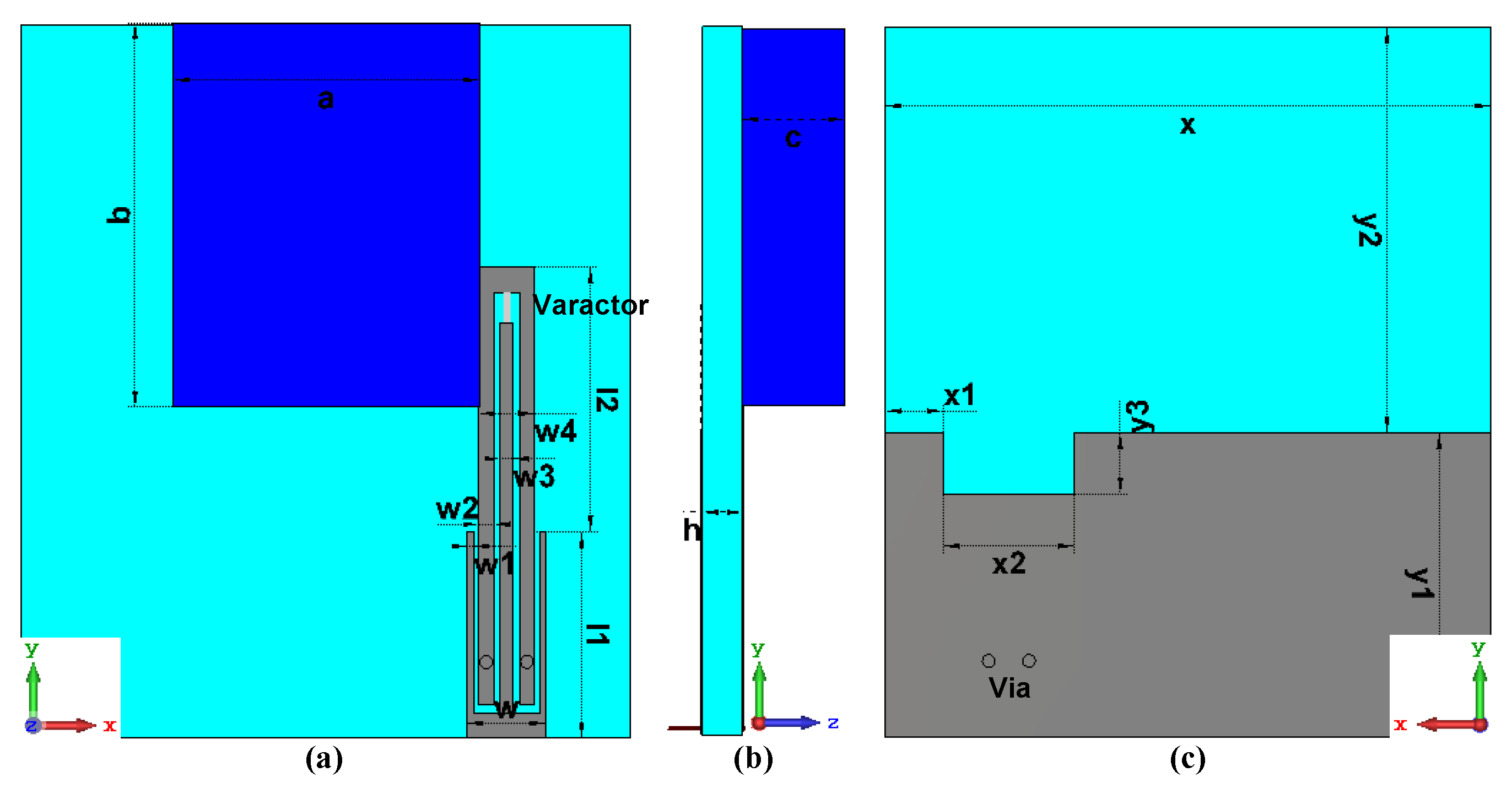
2.1. Antenna Structure

Figure 1 depicts the geometry of the reconfigurable DRA with tunable dual band-notched. It contains a rectangular dielectric resonator (DR) with dielectric constant of 9.9, an offset microstrip feedline integrated with a bandstop filter based on a five-line coupler resonator (FLCR), a varactor diode, and a defected ground plate with a rectangular notch centered around the feed and a FR-4 epoxy substrate with permittivity of 4.4 and loss tangent of 0.025. Rectangular DR excited by asymmetrical feed is easier to excite more resonant modes, which can be used to expand the bandwidth for DRA. Stepped impedance microstrip and defected structure ground plane were introduced for better impedance matching. Dual rejected bands were generated by the FLCR with inverted U- and 山-shaped structures integrated into the microstrip feedline for filtering out the corresponding bands. The continuously tunable characteristic was achieved by the varactor diode with variable capacitor between the two resonant structures.

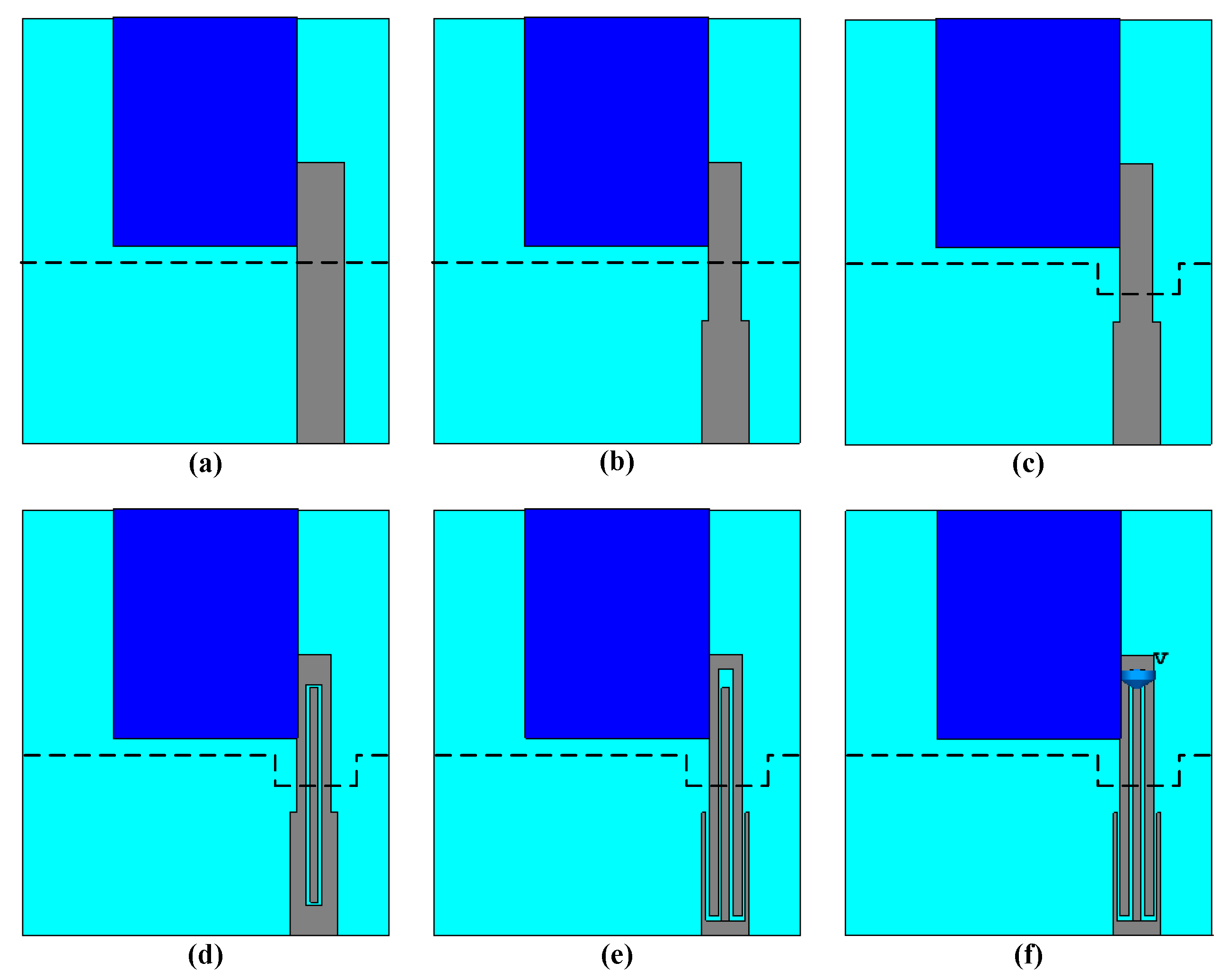
2.2. Design Procedure

For illustrating the evolution process of the proposed DRA, six antenna prototypes were designed (Figure 2). Antenna I, a rectangular DRA excited by offset uniform impedance microstrip, can generate multiple modes with insufficient resonant intensity. Antenna II introduces stepped impedance resonator for microstrip feedline. For Antenna III, a rectangular notch was placed on the partial ground plane for better impedance matching. A square ring slot etching in the feedline was used for producing a slim stopband in Antenna IV. Antenna V introduces a FLCR with inverted U-shaped and 山-shaped structures for forming band-stop filter, with the capability of creating two notched bands. In Antenna VI, a varactor diode, was loaded between these resonator structures to change the capacitance of band-stop filter, eventually making the dual rejected bands adjustable.
For this design, a series of parametric studies were carried out to understand and optimize how the dimensions affect the performance of the dual band-notched DRA by commercial electromagnetic simulation software named Computer Simulation Technology (CST). Simulated input reflection coefficients for the first three antennas are demonstrated in Figure 3. It can be illustrated that the combined technique of stepped impedance resonator and defected ground structure give a wider impedance matching bandwidth step by step with optimized dimensions. Antenna I only operated at dominant mode with a narrow impedance bandwidth around 4 GHz. Antenna II made the dominant mode and higher modes effective together for broadening the bandwidth. Antenna III further achieved a UWB operation bandwidth with the impedance bandwidth 9.86 GHz (3.71–13.57 GHz). To further clarify the multiple modes excited simultaneously of rectangular DRA, simulated E-fields ranging from 0 to 2000 V/m at resonant frequencies of the reference Antenna III are demonstrated in Figure 4, which works in TE11δ mode (at 4.04 GHz), TE21δ mode (at 8.49 GHz), and TE22δ mode (11.69 GHz), respectively. The mode subscribes represent field variations in the directions of x-axis, y-axis, and z-axis in rectangular coordinates, respectively. It can be confirmed that the impedance bandwidth for the proposed DRA is relatively wide owing to the fusion of multi-resonant, offset stepped microstrip feedline and defected ground plane.
Figure 5 demonstrates the reflection coefficients for the last three antennas. Antenna IV operates at notched frequency of 6.06 GHz for the introduction of square ring. The FLCR based on the stepped impedance transformed feedline created two highly selective notched bands within the compact dimension in Antenna V. Antenna III with a varactor diode at the capacitance of 0.63 pF, operated at two rejecting frequency of 5.67 GHz and 9.29 GHz with −10 dB impedance bandwidth of more than 8 GHz. The simulated surface current distributions ranging from 0 to 57.5 A/m of the proposed tunable band-notched antenna at 5.67 GHz and 9.29 GHz with the junction capacitance of 0.63 pF are depicted in Figure 6. The surface current flows around the 山-shaped structure at the rejected frequency of 5.67 GHz and short elements at the rejected frequency of 9.29 GHz, corresponding to their respective quarter-guided-wavelength resonator. For these cases, the surface currents in the DRA caused destructive interference, which resulted in irresponsive antenna. In addition, the gain and radiation efficiency of the proposed antenna with junction capacitance of 0.63 pF are plotted in Figure 7, which also confirms band rejection characteristic at two frequency bands.
A varactor diode was inserted into the FLCR structure of feed network for the proposed DRA. The Skyworks SMV 1405-079LF varactor was selected for this purpose. According to the published datasheet, it can be modeled as the equivalent circuit for the simulation illustrated in Figure 8. The equivalent circuit model was composed of a series resistance (Rs), a resistance inductance (Ls), a parasitic capacitance (Cp), and the junction capacitance (Cj). The values of Rs, Ls, and Cp were, respectively, 0.8 Ω, 0.7 nH and 0.05 pF. The tuning reverse bias voltage of the varactor diode varied Vr from 0 to 30 V, which changed Cj in the range from 2.67 to 0.63 pF, and some typical values are listed in Table 1.

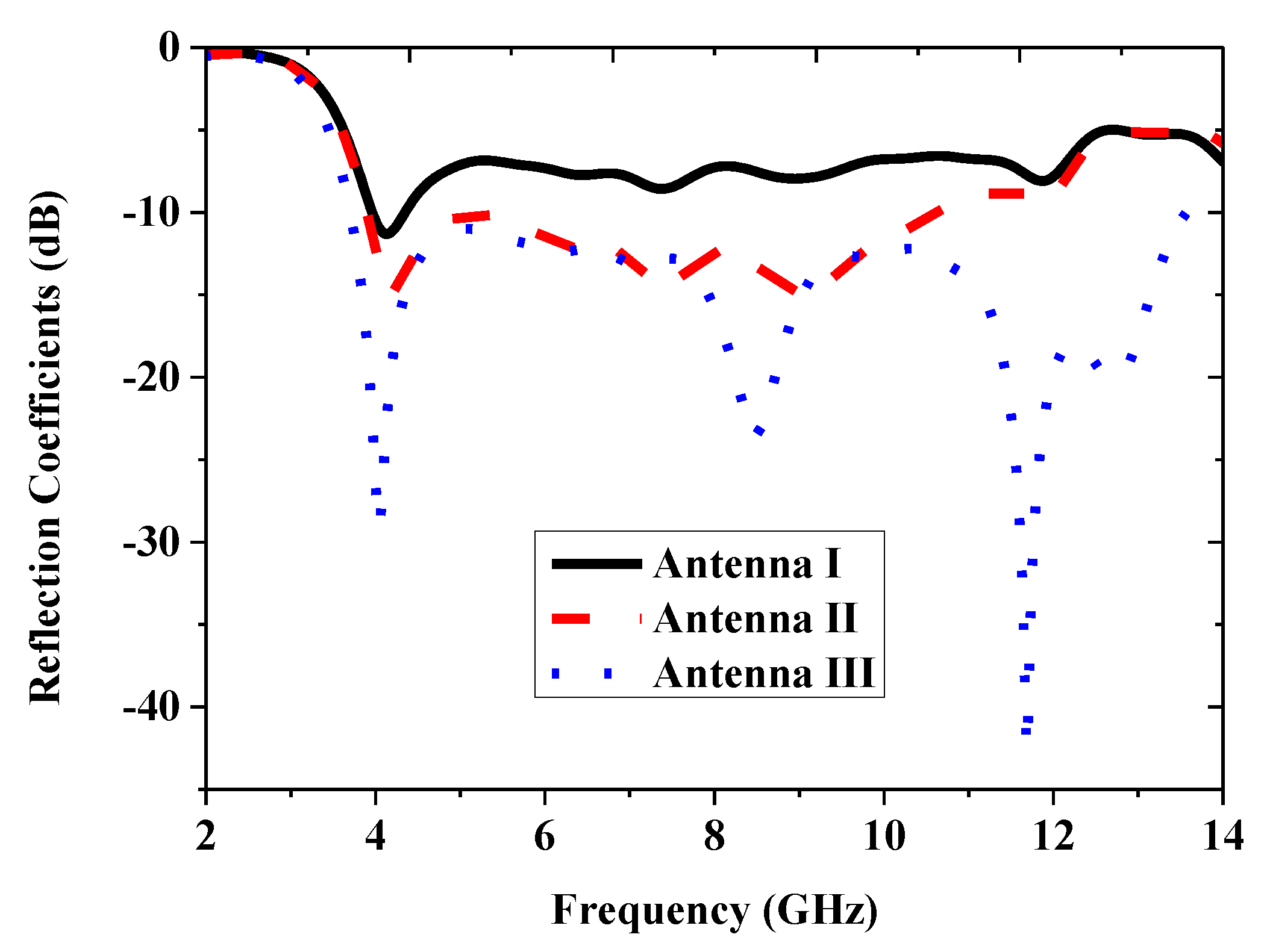
3. Results and Discussion

To demonstrate this type of reconfigurable DRA experimentally, Figure 9 displays a fabricated antenna based on the design with the final dimensions indicated in Table 2. The rectangular DR is made of one type aluminous ceramic. Two wires connected the central feed of 山-shaped structure and the ground plane with metallic via to the upper inverted U-shaped structure separately were used for biasing the varactor diode. In addition, a dc-block SMA connector was used for test between the proposed antenna and the coaxial measurement cable of Agilent-N5227 microwave network analyzer.
The simulated and measured input reflection coefficients for the tunable DRA are shown in Figure 10a,b, respectively, and dual tunable band-notched characteristics are both demonstrated. Moreover, it can be seen that the measured notched bands were continuously tuned from 5.3 (8.74) to 5.84 (8.98) GHz by varying the reversed bias voltage from 0 to 30 V, while the simulated tuning frequency shifted to the up slightly and wider notched band for high frequency range. The small discrepancies can be attributed to the variation in the parameters from the values in the varactor diode data sheet and inaccuracies in the fabrication, assembly, and measurement processes.
The far-field radiation characteristics under four continuously changing reverse bias voltages are demonstrated in Figure 11. The radiation patterns in xoz-plane and yoz-plane have good symmetry, and in xoy-plane change for the offset feed network. All the patterns were quite similar at different principle planes when the antenna is in its tunable band-notched state. The realized gain values of the proposed antenna at one given dual rejected-band state with voltage of 0 V were also obtained: 2.06 dBi (3.9 GHz), 2.23 dBi (4 GHz), 3.2 dBi (8 GHz), and 4.14 dBi (10.6 GHz). The measured results validate the simulated performance characteristics of the dual band-notched rectangular DRA.
Performance comparisons between the proposed dual band-notched DRA and previously relevant literatures for DRAs are listed in Table 3. It can be found that a DRA with wideband of 8.7 GHz and a stopband response of 5.15–5.828 GHz was proposed first, which is based on a DR excited with a monopole antenna and a ring resonator in [13]. In [14], the DRA consists of an L-shaped parasitic strip, and a thin monopole antenna is proposed to achieve a bandwidth of 9.05 GHz along with a notched band of 5.71–6.32 GHz. Moreover, a dual band-notched DRA with U-shaped feedline is realized by embedding a stub and a inverted T-shaped parasitic strip. Slots in the patch connected the feed for DRA, and are used for generating corresponding rejected band in [16] and [17]. However, these designs cannot adjust corresponding notched frequency continuously. The proposed DRA in this paper exhibits not only the characteristic with dual notched bands, but also with tunableness.

4. Conclusions

A reconfigurable dual band-notched DRA is designed and implemented by integrating SMV1405. The wideband characteristic for the proposed DRA is put down to rectangular DR, offset stepped impedance microstrip, and defected ground plane. The inverted U-and 山-shaped resonators are etched in the feedline for generating two notched bands, and the varactor diode between them is used for adjusting the notched bands. The simulated and measured results show that it is a cost-effective solution for DRA to achieve dual-notched-band and tunable characteristic. Currently, the proposed antenna is capable of adjusting the rejected band among 5.3–5.84 GHz and 8.74–8.98 GHz. Additional future work will focus on developing the notch band range for meeting specific application scenario by changing resonator dimensions in the feedline and exploring more wide tunable range by high performance resonators and varactors. It is worth mentioning that the notched bands are arbitrary designated, and the proposed tunable design can be rescaled with the dimension of resonator and applied straightforwardly to other rejected bands of interest.

Author Contributions

Conceptualization, B.L.; Data curation, G.L.; Funding acquisition, J.Q.; Investigation, L.C.

Funding

This research was funded by the National Natural Science Foundation of China, grant number U1633202. and 61731007.

Conflicts of Interest

The authors declare no conflict of interest.

References

  1. Long, S.A.; McAllister, M.W.; Shen, L.C. The resonant cylindrical dielectric cavity antenna. IEEE Trans. Antennas Propag. 1983, 31, 406–421. [Google Scholar] [CrossRef]
  2. Luk, K.M.; Leung, K.W. Dielectric Resonator Antennas; Studies Press Ltd.: Herfordshire, UK, 2003. [Google Scholar]
  3. Petosa, A. Dielectric Resonator Antenna Handbook; Artech House: Norwood, MA, USA, 2007. [Google Scholar]
  4. Petosa, A.; Ittipiboon, A. Dielectric resonator antennas: a historical review and the current state of the art. IEEE Antennas Propag. Mag. 2010, 52, 91–116. [Google Scholar] [CrossRef]
  5. Ryu, K.S.; Kishk, A.A. UWB dielectric resonator antenna having consistent Omnidirectional Pattern and low cross-polarization characteristics. IEEE Trans. Antennas Propag. 2011, 59, 1403–1408. [Google Scholar] [CrossRef]
  6. Ge, Y.; Esselle, K.P.; Bird, T.S. Compact dielectric resonator antennas with ultrawide 60%–110% bandwidth. IEEE Trans. Antennas Propag. 2011, 59, 3445–3448. [Google Scholar] [CrossRef]
  7. Bialkoski, M.E.; Abbosh, A.M. Design of UWB planar antenna with improved cut-off at the out-of-band frequencies. IEEE Antennas Wirel. Propag. Lett. 2008, 16, 408–410. [Google Scholar] [CrossRef]
  8. Deng, J.Y.; Hou, S.; Guo, L.X. Wideband-to narrowband tunable monopole antenna with integrated bandpass filters for UWB/WLAN applicaions. IEEE Antennas Wirel. Propag. Lett. 2017, 16, 2734–2737. [Google Scholar] [CrossRef]
  9. Zaker, R.; Ghobadi, C.; Nourinia, J. Bandwidth enhancement of novel compact single and dual band-notched printed monopole antenna with a pair of L-shaped slots. IEEE Trans. Antennas Propag. 2009, 57, 3978–3983. [Google Scholar] [CrossRef]
  10. Chen, B.; Leung, W.; Wang, A.G.; Zhao, G.H. Compact ultra-wideband antenna with reconfigurable notched bands. Electron. Lett. 2012, 48, 1175–1179. [Google Scholar] [CrossRef]
  11. Horestani, A.K.; Shaterian, Z.; Naqui, J.; Martin, F.; Fumeaux, C. Reconfigurable and tunable S-shaped split-ring resonators and application in band-notched UWB antennas. IEEE Trans. Antennas Propag. 2016, 64, 3766–3779. [Google Scholar] [CrossRef]
  12. Vendik, I.B.; Rusakov, A.; Kanjanasit, K.; Hong, J.; Filonov, D. Ultrawideband (UWB) planar antenna with single-, dual-, and triple-band notched characteristic based on electric ring resonator. IEEE Antennas Wirel. Propag. Lett. 2017, 16, 1597–1600. [Google Scholar] [CrossRef]
  13. Niroo-Jazi, M.; Denidni, T.A. Experimental investiagtions of a novel ultrawideband dielectric resonator antenna with rejection band using hybrid techniques. IEEE Antennas Wirel. Propag. Lett. 2012, 11, 492–495. [Google Scholar] [CrossRef]
  14. Abedian, M.; Rahim, S.K.A.; Danesh, S.; Khalily, M.; Noghabaei, S.M. Ultrawideband dielectric resonator antenna with WLAN band rejection at 5.8 GHz. IEEE Antennas Wirel. Propag. Lett. 2013, 12, 1523–1526. [Google Scholar] [CrossRef]
  15. Abedian, M.; Rahim, S.K.A.; Danesh, S.; Hakimi, S.; Cheong, L.Y.; Jamaluddin, M.H. Novel design of compact UWB dielectric resonator antenna with dual-band-rejection characteristics for WiMAX/WLAN bands. IEEE Antennas Wirel. Propag. Lett. 2015, 14, 245–248. [Google Scholar] [CrossRef]
  16. Wang, Y.F.; Denidni, T.A.; Zeng, Q.S.; Wei, G. Band-notched UWB rectangular dielectric resonator antenna. Electon. Lett. 2014, 50, 483–484. [Google Scholar] [CrossRef]
  17. Denidni, T.A.; Weng, Z. Hybrid ultrawideband dielectric resonator antenna and band-notched designs. IET Microwaves Antennas Propag. 2011, 5, 450–458. [Google Scholar] [CrossRef]
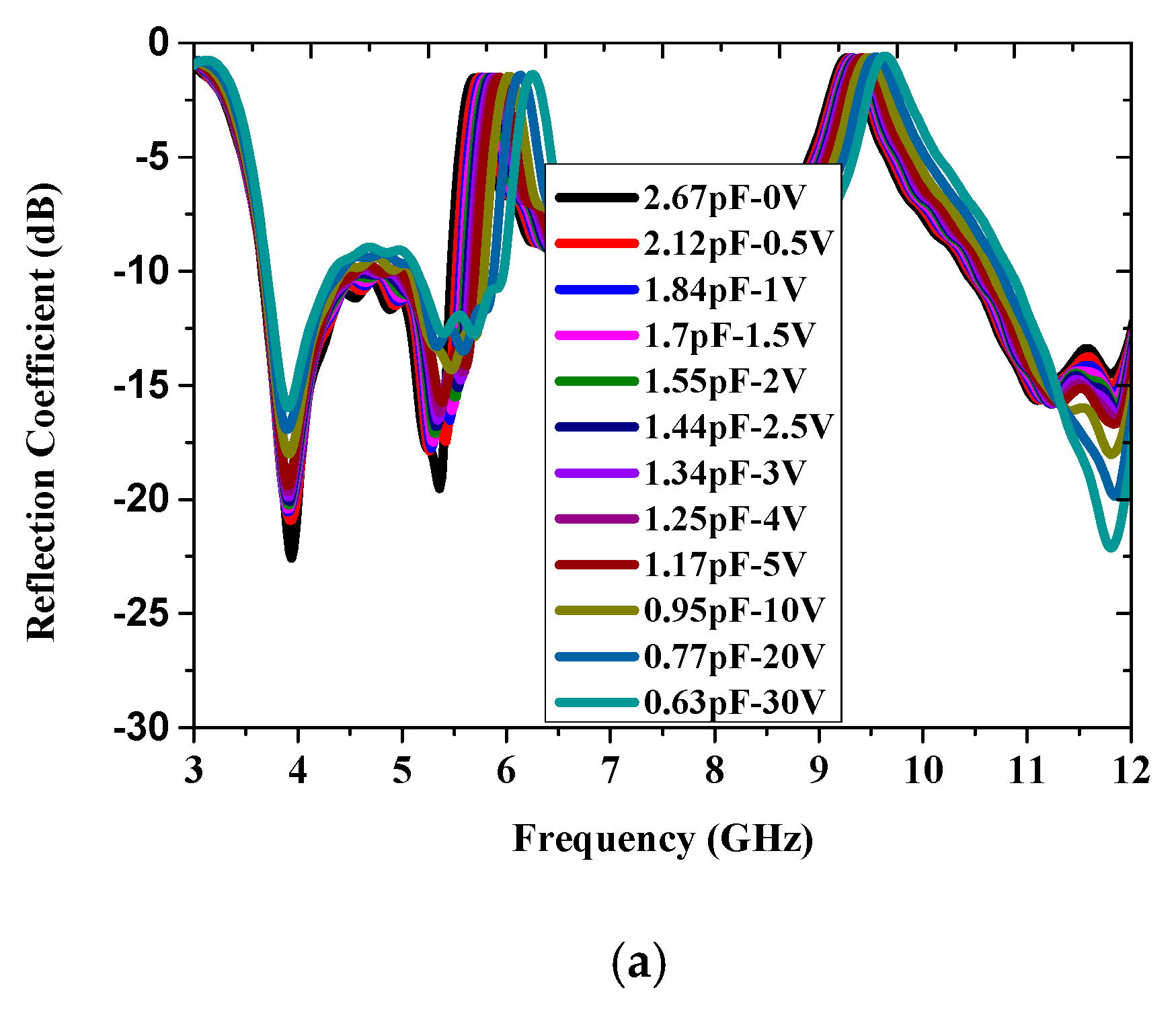
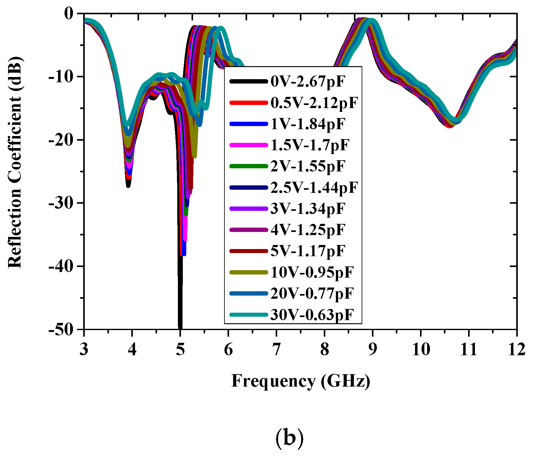
Figure 1. Configuration of the proposed tunable band-notched reconfigurable DRA: (a) top view; (b) side view; and (c) bottom view.
Electronics 08 00472 g001
Figure 2. Evolution process of the proposed antenna: (a) Antenna I; (b) Antenna II; (c) Antenna III; (d) Antenna IV; (e) Antenna V; and (f) Antenna VI.
Electronics 08 00472 g002
Figure 3. Simulated reflection coefficients of the first three reference antennas.
Electronics 08 00472 g003
Figure 4. Simulated E-fields of reference Antenna III: (a) TE11δ mode at 4.04 GHz; (b) TE21δ mode at 8.49 GHz; and (c) TE22δ mode at 11.69 GHz.
Electronics 08 00472 g004
Figure 5. Simulated reflection coefficients of the last three reference antennas.
Electronics 08 00472 g005
Figure 6. Surface current distribution of the proposed antenna with junction capacitance of 0.63 pF: (a) 5.67 GHz and (b) 9.29 GHz.
Electronics 08 00472 g006
Figure 7. Gain and radiation efficiency of the proposed antenna with junction capacitance of 0.63 pF.
Electronics 08 00472 g007
Figure 8. Simplified equivalent varactor Circuit.
Electronics 08 00472 g008
Figure 9. Prototype of the proposed DRA: (a) top view and (b) bottom view.
Electronics 08 00472 g009
Figure 10. Reflection coefficient of the proposed tunable DRA: (a) simulation and (b) measurement.
Electronics 08 00472 g010aElectronics 08 00472 g010b
Figure 11. Normalized radiation pattern of the proposed DRA at 4 GHz: (a) 0V; (b) 1.5V; (c) 5.0V; and (d) 30.0V.
Electronics 08 00472 g011aElectronics 08 00472 g011b
Table 1. Capacitance vs reverse voltage of SMV 1405-079LF.
Vr (V)00.51.01.52.02.5
Cj (pF)2.672.121.841.701.551.44
Vr (V)3.04.05.010.020.030.0
Cj (pF)1.341.251.170.950.770.63
Table 2. Final dimensions of the proposed antenna.
Parametersabchl1l2
Value (mm)121541.68.110.4
Parametersw1w2w3w4wx
Value (mm)0.30.60.52.23.124
Parametersx1x2y1y2y3εr
Value (mm)2.35.212162.49.9
Table 3. Performance comparison with other band-notched DRAs.
Ref.Feed TechniqueWideband Range (GHz)Notched-Band Range (GHz)Notched-Band No.Tunable Characteristic
[13]Probe2–10.75.15–5.8281No
[14]Microstrip3.05–12.15.71–6.321No
[15]Microstrip3.03–12.523.22–4.06
4.84–5.96
2No
[16]Probe + Patch3.6–125.1–61No
[17]Coplanar Waveguide3.1–10.63.35–3.8
5.1–6.1
2No
Our workMicrostrip3.71–11.275.3–5.84
8.74–8.98
2Yes

