Abstract
In this paper, in order to handle the high nonlinearity and the sophisticated disturbance in marine engines, a variable sampling rate based active disturbance rejection controller is developed for engine speed control. In the proposed method, the Active Disturbance Rejection Control (ADRC) is designed with the consideration of the practical application in engine speed control that is known as the Crank-angle (CA) based or event-based sampling and control, which means the sampling interval varies with the engine speed. Such a problem has not been discussed in any previous study regarding the application of ADRC in engine control. To this end, this paper discusses the convergence of the variable sampling rate based Extended State Observer (ESO), as well as its parameters that guarantee stability. To verify the proposed control scheme more properly, a cycle-detailed hybrid nonlinear engine model is employed. Finally, simulations are carried out on the Hardware-in-the-loop (HIL) system to assess the superiority of the proposed strategy. The comparative results with a Fuzzy-Proportional-Integral-Derivative (PID) controller demonstrate that the proposed control scheme has better adaptation to engine speed, load disturbances, and stronger robustness towards model uncertainties, which indicates a promising reduction of time and burden for calibrating the controller. It also proved that the proposed CA based ADRC by variable sampling rate method outperforms the general fixed sampling rate ADRC, which is widely used in previous works. Moreover, the successful application of the proposed algorithm via CA based strategy in a real Engine Control Unit (ECU) indicates its huge potential in practical engine control.
1. Introduction
Marine diesel engines are widely used in the domain of ship propulsion [1,2,3]. For marine main engines, the most crucial task is to retain engine speed steady under desired engine speed in the presence of the inherent instabilities and disturbances coupled with the unpredictable external environment [4]. On the one hand, the diesel engine is highly nonlinear and engine speed is related to various aspects, such as the operating condition, coolant and intake air temperature. On the other hand, as the vessels cruise on the sea, the maritime condition seriously affects the engine speed [2,5]. In moderate sea conditions, the ocean current introduces wave disturbance to the propeller, causing the engine with undesired speed fluctuation. While in rough or extreme condition, partial or whole the propeller disk would periodically emerge and submerge from the sea surface, leading to large variations in the engine speed [6]. Hence, without an accurate and robust speed governor, the variation of engine speed would lead to abnormal operating conditions [1], which decreases the service life of engines and even results in premature failure of the transmission system in case of severe speed fluctuation [7]. Moreover, sustained over-speed will cause irreversible damage in the engine system [4], while sharply decreasing in engine speed may make the engine stall, resulting in serious safe problem. From other aspects, for example, the performance of engine speed control has a significant influence on the fuel economy and exhaust emission [5,8]. The design of speed controller for marine engines should under the limitation of the increasingly strict emission regulations (see in [9]), which poses a more tough task for the engine speed control. High performance speed controller can help to reduce the fuel consumption and emission in a certain degree.
As can be found in the literature, vast control techniques have been investigated for marine engine speed control. Some of them range from the model-independent methods, such as classical Proportional-Integral-Derivative (PID) control [10], Sliding Model Control (SMC) [2,5], to the model-based approaches, e.g., control [11] and Model Predictive Control (MPC) [12,13]. Some others are designed by synthesizing classical PID approach with intelligent algorithms, such as fuzzy technique [14,15]. Substantial achievement has been obtained, yet there are still some drawbacks among these approaches. For instance, the classical PID controllers need to be readjusted when external conditions deviate far away from their calibrated situations; the chattering phenomenon and parameters tuning in SMC need to be dealt with well; the implementation of MPC is complex and its cost should be considered; the experience and knowledge base are hard to be effectively gained for fuzzy control system. As mentioned above, the engine speed steady is affected strongly by the internal uncertainties and external load disturbances; therefore, additional attempts have been drawn to the Active Disturbance Rejection Control (ADRC), which has proven to be with strong robustness towards uncertainty and disturbance.
ADRC was first proposed by Han [16] to overcome the drawbacks of the conventional PID. In the ADRC theory, both the internal uncertainty and external disturbance are lumped as the “total disturbance”, which is treated as a new state of the system then estimated and compensated by the Extended State Observer (ESO) [17]. Its considerable performance has been verified by extensive industrial applications, e.g., [18,19,20], and a summary introduction can be found in [21]. Recently, for marine engine speed control, some ADRC or ESO based controllers are developed in simulation environments. In [22], a continuous-time ADRC controller was proposed for a MAN B and W low-speed diesel engine and its control effect was assessed on a simplified transfer function engine model. In [23], a combined discrete-time controller based on Cerebellar Model Articulation controller (CMAC) and ADRC was verified on a simplified engine model where the model of propeller and hull dynamics were considered. In the authors’ previous work [24], a controller was obtained by integrating nonlinear and linear ADRC and its control effect was tested on a Crank-angle (CA) based Mean Value Engine Model (MVEM) rather than a simple engine model. Although these ADRC related controllers showed good performance, the ADRC methods investigated therein ignore the crucial characteristics in engine speed control (e.g., the event-based fuel injection control), which are discussed as follow.
First, Internal Combustion (IC) engines are typical event-based system, due to the fact that the in-cylinder process is consisted of four distinct stages, i.e., intake, compression, expand, and exhaust, which are CA dependent [25,26]. Such characteristics make it more reasonable for the practical speed controller to be CA based rather than time based. By doing such, the control actions can be synchronized with the CA [27]. Numerous researchers have studied the benefits of the CA based control. In [25], for a Spark Ignition (SI) engine, linear quadratic regulator (LQR), fuzzy control, and SMC were designed and compared in the CA domain. More recently, in [27], a gain-schedule speed controller was designed in the CA domain for an ethanol engine.
In order to demonstrate more clearly the speed control issue for IC engines, its basic scheme diagram is illustrated in Figure 1. Generally, for IC engine speed control, the crankshaft and camshaft angular position sensors are necessary for providing the exact fuel injection timing. This can be realized by mounting two specific toothed wheels on the crankshaft and camshaft. As shown in Figure 1, for instance, the toothed wheel for crankshaft should be with at least one missing tooth for providing an absolute angular position reference, and for the camshaft, at least one tooth for detecting the Top-dead-center (TDC) of a certain cylinder should be provided. More details can be found in [28]. The fuel injection can only be executed at a fixed CA, which means the control input (fuel injection mass) can only be updated once for the individual cylinder within a working cycle ( rad CA for a 4-stroke engine). Such traits mean that if a controller is structured based on a fixed sampling interval, the calculation of control input cannot be synchronized with the in-cylinder powering process unless it is computed at the correct CA position. It is known as the event-based control scheme for engine speed control, which can be treated as a variable sampling interval control issue as the sampling time is related to engine speed, that is
where represents the stroke of the engine (for 2-stroke engine, = 1, for 4-stroke engine, = 2), is the number of cylinders, is engine speed in rpm.
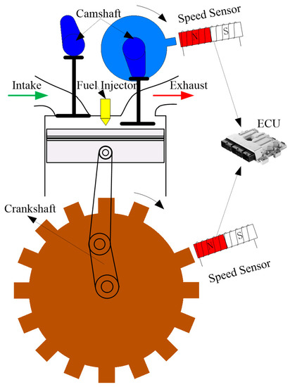
Figure 1.
The schematic diagram for practical engine speed control system.
As stated above, there comes a problem when, in general, according to [29,30,31], the sampling interval is designed to be constant in discrete-time ADRC and it must be small enough to keep accuracy. However, the sampling period for engine speed control varies with the engine speed as shown in Equation (1). Unfortunately, as the best as the authors know, including the IC engines control domain, there is no literature reported concerning digital implementation of ADRC with variable sampling rate. Most of the reported papers focus on the discrete-time ADRC with a fixed sampling rate. Although in [32] the event-triggered ESO is discussed, the sampling interval is still fixed. We should point out that the variable sampling rate-based control (also known as event-based control, or magnitude-driven sampling-based control, etc.) has drawn considerable attention in past years, especially in the domain of wireless sensor network [33]. In such a control method, the sampling is based on event, which makes it hard to obtain effective information from sensors or processes by using fixed sampling time [34]. A more detailed introduction and advantage of such control scheme can be found in [33,34,35] and the references therein. Hence, it is of importance to study the variable sampling rate ADRC to improve the control performance for engine speed control. In addition to the IC engine domain, this kind of method also can be considered in speed control for DC motors where the rotation speed is measured via photoelectric encoder or limited speed sensors as the sampling rate also related to the rotation speed, e.g., [36].
Second, when ADRC is implemented via digital controllers where the system outputs are sampled, a discretization approach needs to be considered due to its significant influence on the control effect and stability of the control system [29,37], especially when the sampling time is large [30]. In previous works that have focused on the application of ADRC in engine speed control, scant attention has been drawn to this issue. In the authors’ previous work [24] and another’s work [8,23], the Euler approximation method was directly adopted to design ADRC based engine speed controller with a constant sampling interval. Such an issue has not been studied because the aforementioned previous work designed the controller by using a short sampling interval without considering the practical control process in IC engines, i.e., the CA based control scheme. For the CA based control, we found that when engine speed was low the discretization method was not stable due to the large sampling period in the low speed region. Hence, a more accurate discretization method borrowed from [38] is employed in this study.
To test the variable sampling rate of ADRC before applying to a real engine, a CA based cylinder-by-cylinder mean value engine model (MVEM) was used. Such a model can simulate the discrete torque generation and cylinder-by-cylinder variation in IC engines, which makes the design of controller more practical. In [24], it has been proven that the inherent speed fluctuation caused by the aforementioned traits has a significant influence on the performance of ESO. Thus, it is necessary to verify the control effect of ADRC by such a model. The advantages of designing a controller by using CA based engine models can be found in some other recent works [12,24,27,39]. In this study, the engine model not only has the traits in [27,39], but also considers the discrete torque generation and cylinder-by-cylinder variation. Hence, it is more practical and reasonable for the algorithm verification.
Besides, it should be pointed out that, in practical, the engine speed could only be measured when the teeth rim goes through the installed sensors. Moreover, the mean engine speed calculated by tooth-to-tooth engine speed within a specified segment of CA ( rad CA for a 4-stroke 6-cylinder engine) is employed as the input for controller, which contributes extra delay in the close-loop control system [40]. This issue has not been considered in previous works concerning the applications of ADRC in diesel engines. Hence, a Hardware-in-the-loop (HIL) system where the engine signals as in a real engine (such as crankshaft and camshaft signals) can be provided and is used to verify the proposed scheme. The Engine Control Unit (ECU) is developed by automatic code generation tool on an NXP Freescale microprocessor MPC5644 from the company of NXP Semiconductors.
As stated above, addressed in this paper is the variable sampling rate ADRC for marine engine speed control with the consideration of practical control process, including the CA based fuel injection and the delay in measuring engine speed. The main contribution of this study is listed as follows:
- The variable sampling rate based ADRC is designed for marine engine speed control.
- The stability of the variable sampling rate ESO is analyzed and the parameters tuning is discussed for the variable sampling rate ADRC based engine speed controller.
- To demonstrate the control effects of the proposed method, abundant simulations are carried out on the CA based engine model by using the HIL system where a real ECU is used.
The rest paper is structured as follows. In the Section 2, a modified MVEM is introduced. In the Section 3, the variable sampling rate ADRC is designed for marine engine speed control, and the stability of variable sampling rate ESO is analyzed. In the Section 4, the simulations for verifying the proposed algorithm is carried out on the HIL system by comparing with a Fuzzy-PID controller. In Section 5, the analysis of the results and future work are discussed. The conclusion is given in Section 6.
2. Engine Model Description
The target engine is a four-stroke six-cylinder diesel engine equipped with turbocharger. Figure 2 demonstrates the thermodynamic volumes for the engine system. The engine model is comprised of five parts: intake manifold, exhaust manifold, cylinders, intercooler, and turbocharger. The control input is the fuel injection mass per cylinder per cycle (mg/c.c.), denoted as , which is controlled by ECU. We assume that the fuel injection mass is the only controlled variable and otherwise controlled variables such as injection advance angle are optimal.
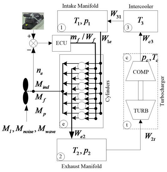
Figure 2.
The block diagram of the marine engine model.
2.1. The General MVEM
Note that the MVEM used in this study was originally used in [41,42] and has been validated well therein. Moreover, this MVEM can be accessed online, based on which plenty of research has been published [43]. In the authors’ previous study [2], marine load torque and wave disturbance are added to study the engine speed control of marine diesel engine for propulsion. More recently, the authors modified it with the consideration of the discrete indicated torque generation process and the unbalanced power ability among cylinders [12,24]. Hence, only the main equations are given. More details can refer to the references mentioned above. The intake and exhaust dynamics can be described as follows,
where
with , . is the temperature, denotes pressure, means the volume, is the mass flow rate, the subscript “1” and “2” denote the intake and exhaust manifold, the subscript “3” means the intercooler, the subscript “e” means the cylinders, and the subscript “c” denotes the turbocharger, the subscript “ij” means the mass flow rate from volume “i” to “j”. and are the ideal-gas constants for intake gas and exhaust gas, respectively, is the volumetric efficiency, which relates to intake manifold pressure , engine speed , the coefficients , , and . is the mass fuel rate injected to cylinders, which can be calculated by using the control input, i.e., . is the volume of the total cylinders.
Assuming the inter-cooler is ideal, i.e., there is no pressure loss, no mass accumulation, and the efficiency is perfect, resulting in the following equations.
The turbocharger dynamics can be given as
where denotes the power, subscript “t” means the turbine, is the turbine speed, is the efficiency of turbocharger, which needs to be calibrated by experimental data, is the inertia of the shaft, is the turbo-lag.
Finally, for a diesel engine used for propulsion, its rotational dynamics can be given as
with
where is the total rotary inertia (including the incidental water effect), is the total indicated torque generated by all the cylinders. represents all the resistance torque, including the friction torque (decided by the coefficients , , and engine speed ), the friction torque , the pumping torque , the total bounded noise disturbance which can be modeled by bounded Gaussian noise, the load torque , the additional torque from the ocean current . is the fuel low calorific value, is the indicated efficiency which can be given as a function of engine speed and Air-to-fuel Ratio (AFR) . is the load factor which is affected by various aspects, such as the ship size and the load on the ship.
2.2. The Modified MVEM by CA Resolved Method
To model the cycle details in reciprocating engines, some innovative methods have been proposed in [26,44] where hybrid models (including both discrete and continuous models) are structured to exhibit the discrete torque generation process. They focused more on the discrete behaviors in torque generation and only limited at idle mode. However, some other important characteristics (such as the working imbalance among cylinders and cycle delays) were neglected. Some other methodologies employ the CA based model to model the variations of transient speed, torque, and in-cylinder process during a cycle. The in-cylinder pressure map is required in some of them, e.g., [45], which makes it higher cost and more difficult to be implemented [46,47]. Other methods use the Warson or/and Wiebe combustion functions to describe the in-cylinder combustion process, e.g., [48], which not only need more detailed structural parameters of the engine but also demand more computation burden and time [49].
Considering the deficiencies listed above, we previously introduced the idea to modify the common MVEM [26,44,50], wherein we expected to keep the advantages in the MVEM. Meanwhile, to simulate the inherent speed fluctuation caused by discrete torque generation and cyclic deviations among cylinders without making the engine model more complex and harder to be executed in computation, the aforementioned model we carried out. Hence, a cycle-detailed hybrid nonlinear engine model is simply described in this section. For more details about such an engine model, please refer to the authors’ previous works [12,51].
To determine the timing sequence of the four strokes in each cylinder during its working cycle, the CA signal is introduced by
where operator ‘mod’ means modulus.
Compared with the MVEM above, the proposed model treats each cylinder individually. In the proposed engine model, for each cylinder, the indicted torque is replaced by the mean value during the power stage rather than the mean value during the whole in-cylinder cycle. Hence, for a certain cylinder i, the discrete torque generation process can be given as
with
where , is a block pulse function, which represents the discrete torque generation in IC engines. and denote the fuel mass flow rate and the indicated efficiency of the cylinder i. is the firing duration angle ( rad CA for the target engine), is is defined as the cylinder-by-cylinder variation of the cylinder i.
Then the total indicated torque generated by all the cylinders is
For other dynamic equations in the individual cylinder, there is no any difference with the MVEM, only the whole effects from the individual cylinders should be lumped together at the end. They can be given as follows:
2.3. The Comparisons Between the Proposed Engine Model and the MVEM
Under the same operating condition, the indicated torque and speed curves for the proposed engine model and MVEM are compared in Figure 3. The right side of Figure 3 denotes the enlarged figures within one engine working cycle. For the proposed engine model, the discrete torque generation process in individual cylinder is clearly illustrated in Figure 3a. Figure 3b shows that the mean effect of the total indicated torque in the proposed engine model is almost the same as that in MVEM. It can be observed from Figure 3c that the inherent speed fluctuation can be modeled in the proposed model, where the speed fluctuation is significantly larger than that in the MVEM.
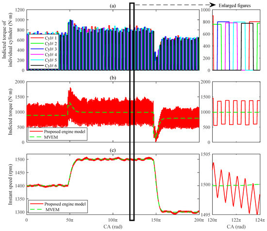
Figure 3.
The comparisons between two engine models: (a) Individual cylinder indicated torque in the proposed hybrid engine model; (b) Total indicated torque in both engine models; (c) The speed responses in both engine models. (The sub-plots in the right side are the enlarged figures during one working cycle). MVEM: Mean Value Engine Model; CA: Crank-angle.
Remark 1.
The MVEM has been verified in the works provided by Wahlstrom and Eriksson [41,42]. In this study, some modifications are made based on the original engine model, including the torque load, the crankshaft rotational dynamic, and the individual cylinder-based torque generation. The speed responses between the two models are almost the same (see Figure 3c), hence, it is reasonable to conclude that the proposed engine model is equivalent with the original MVEM and it can be used to verify the control algorithm.
3. Controller Design
3.1. The Variable Simpling Rate ADRC for Engine Speed Control
For the control design, the MVEM is enough, so that reconstructing the (5) gives
Assuming , is a constant and is an unknown value, then (10) can be written as follow:
where is regarded as the generalized disturbances.
Treating as an extended state, set , , , , meanwhile, consider the discrete-time CA based speed measurement and control, which means the measured output and the control input are held to be constant before the next sampling. Hence, the augmented state space model for (11) can be structured as
where , , , , , means the real time at the beginning of the sampling instance k, can be calculated by (1), which is a function of the engine speed . Note that is known, as for is calculable, i.e., .
In order to match with the practical control condition that the sampling and control of engine speed are CA based, a discrete-time observer is designed for the state space model (12) with the variable sampling interval at the sampling instance k. As stated in [52], the discretization method is of importance. In general, most previous works made use of the Euler approximation method [53], which has been proven with a serious problem of stability when the sampling period is large. Miklosovic and Gao compared a couple of typical discretization approaches in [52]. More recently, Herbst proposed a more accurate discretization method [38], which is borrowed in this study, due to that the sampling interval is big when engine speed is low. For simplicity, denoting , we can get the discrete-time observer as follow:
where , , , is the estimated state vector, , is the estimated output.
Note that the above ESO state equation is gained under the following assumptions.
Assumption 1.
The lumped disturbance functionis continuous and differentiable.
Assumption 2.
The lumped disturbance functionis bounded, i.e.,.
Assumption 3.
In engine speed control, for,, the following equations are satisfied
which means that, during the controllable engine speed range, the engine speedand the total disturbancewould not change very much between two sampling instances.
3.2. Stability Analysis of the Variable Sampling Rate based ESO
The sampling period used in Equation (13) varies with the engine speed, which is different with the previous works concerning the convergence analysis on the ESO [30]. Here, we need to discuss the stability of the variable sampling rate based ESO.
If the following Equation (15) is satisfied, we can conclude that the discrete-time ESO with variable sampling period is convergent [30].
According to [38], the error dynamics can be given as
where , is the output error.
Under assumption 3, (16) can be rewritten as
For Equation (17), if pair [] is observable, then there exist can stabilize .
As the observable matrix is
It is obvious that pair [] is observable if . It is always can be satisified as the engine speed cannot be infinite (assumption 3).
As a result, if spectral radius of satisfies , the error system in Equation (17) is asymptotically stable.
The characteristic polynomial of can be given as
Defining , according to the condition of , we can discuss the spectral radius of in the following three cases.
If , has multiple eigenvalue, that is . The . Then the asymptotically stable condition for the system (17) can be given as follow:
If , has two real eigenvalues, they are . Then, the . Hence, the asymptotically stable condition for the system (17) can be given as
If , has two imaginary eigenvalues, they are . The . The asymptotically stable condition for the system (17) can be got as
which can be further simplified to be
Remark 2.
From Equations (20)–(22), we get a set of constraints forto guarantee the stability of error system (17). But for designing theeasily, we need efficient approach, such as the bandwidth method proposed in [54]. It is interesting that, when we employ such method, it is a special condition of Equation (21).
3.3. Parameters Design
The control law can be given in the form of state feedback by using the estimated state variables, i.e.,
where is the reference speed at the sampling instance k, denotes control bandwidth.
Finally, the proposed control scheme can be shown in Figure 4. The calculation of ESO and control law is triggered by the CA signal from speed sensors which guarantee the synchronization between the control input and CA.
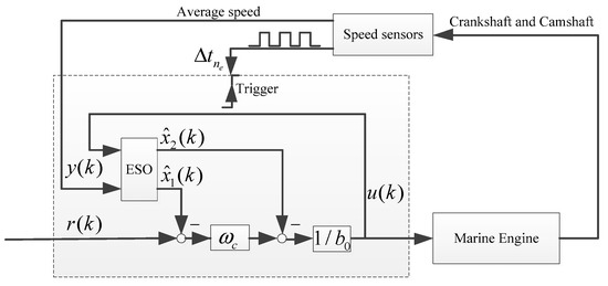
Figure 4.
The block diagram of the variable sampling rate Active Disturbance Rejection Control (ADRC) for marine engine speed control.
The bandwidth approach means is designed to be in one location, i.e. . According to [52], we can get
Under such parameters, when , (20) is always true, because .
Remark 3.
Observing Equation (24), we know that, actually,should be designed according to engine speed, as the settling timeis varying with engine speed. For instance, when engine speed is low, the response of engine speed is slow, so that it cannot reach a short settling time as when it runs at high speed. Hence, in this study, we modifyto be
with,,,, whereis a scale factor according to engine speed at instance k and the nominal speed, in general, the rating condition,andare the observer bandwidth and control bandwidth under the nominal speed, respectively,andmean the modifed observer and control bandwidth, respectively.
Remark 4.
The design of the modified parameters does not need extra calibration or tuning. Once the parameters under nominal condition is gained, the parameters in other speed conditions can be calculated directly by a scale parameteraccording to the engine speed at the sampling instance k.
4. Evaluation of the Variable Sampling Rate based ADRC Controller for Engine Speed Control by HIL System
In this section, the proposed control scheme is evaluated based on the proposed engine model by using HIL test platform. Note that the load torque is normalized with = 0.004, noise load is banded white noise and the cylinder-by-cylinder variation degree is designed to be .
The experimental setup is shown in Figure 5. The engine model that is structured in the Matlab/Simulink environment is downloaded into the NI PXI-8880RT which can simulate the engine in real time. The necessary signals for engine control, such as crankshaft, camshaft, are provided to the ECU by the NI PXI-8880RT hardware (including engine speed simulation module, digital, and analog modules). Note that such crankshaft and camshaft signals are modelled strictly as the signals from a real engine (as illustrated in Figure 1). The control input (fuel injected mass) is acquired from the real fuel injectors by the large current acquisition module in the form of injection timing and injection pulse width then transferred into the engine model. The configuration for input and output signals and the settings for simulations are manipulated by the experimental manager software, NI VeriStand. As a result, the control effect of the proposed method can be validated via the closed-loop simulation.
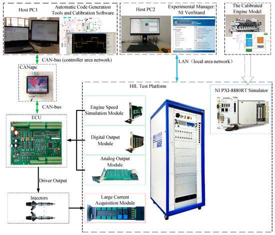
Figure 5.
The experimental setup by using the Hardware-in-the-loop (HIL) test platform.
Additionally, it should be noted that the ECU is established based on the NXP Freescale MPC5644 microcontroller and communicates with host PC by CAN (controller area network) bus using Vector’s CANape calibration system. The proposed algorithm and the basic code for engine control are programed in the Matlab/Simulink environment via the automatic code generation technology.
4.1. The Comparative Controllers
Generally, as commented in [55], it is unreasonable to evaluate a new designed control strategy by comparing it to a simple PID using rough tuned techniques (i.e., Ziegler-Nichols tuning). Hence, we designed a well-tuned Fuzzy-PID for comparative simulations. The fuzzy rules can refer to [14].
In the Fuzzy-PID, an incremental PID structure with anti-windup scheme is employed as follows.
where , and gain coefficients at the sampling instance k, which was gained by fuzzy technique according to , , and , which are the non-saturated and saturated control inputs, respectively; and are the lower and upper bounds of the control input, respectively.
Note that the mentioned fuzzy-PID is also based on variable sampling interval, its sampling and control is triggered by CA signal as the same as in the proposed controller. Hence, for simplicity, it is defined to be VSR-Fuzzy-PID.
4.2. The Design of Control Parameters for Controllers
The VSR-Fuzzy-PID controller is tuned via the trail-and-error approach. Finally, the initial coefficients are designed to be , the ranges of , , and are given as follows
with , .
As for the proposed method, according to Equation (25) and Remark 3, if the rated operation (engine runs at 1800 rpm with full load) as a nominal condition is chosen, the control parameters under such condition can be given as , , . Then, in other speed regions, the control parameters are We define this control scheme to be a variable sampling rate ADRC, i.e., VSR-ADRC.
In order to show the difference between the VSR-ADRC and the general fixed sampling rate ADRC (FSR-ADRC), a FSR-ADRC was also compared. Its control parameters were designed to be the same as in VSR-ADRC, but its sampling and control interval was fixed at 0.01 s.
4.3. The Control Performance
To assess the control effect of the proposed VSR-ADRC, the evaluation criterions in overshoot, settling time, integrated absolute error (IAE) of the output error, and the fuel consumption are used.
According to [56], the IAE of the output error can be calculated by
4.3.1. The Influence of Discretization Methods on the Control Effect
To show clearly the control effects obtained using the Euler approximation and the adopted method, the comparisons of them under different engine speed are plotted in Figure 6.
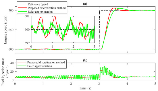
Figure 6.
The control performance comparison of different discretization methods for ADRC with variable sampling rate at low speed region: (a) The speed response; (b) The control input.
As shown in Figure 6, when engine speed is low (600 rpm), the engine speed cannot keep steady in the controller where the ESO is discretized using the Euler approximation. Its control input shakes vigorously and tends to diverge, which should be avoided for preventing the engine from damage. However, for the controller where the ESO is discretized by the employed approach, the engine speed can retain steady. Moreover, the dynamic performance of the Euler approximation-based controller is inferior to the employed approach, as its settling time is significantly longer.
Note that Figure 6 is got with the same control parameters in both controllers. But no matter how the parameters are tuned in the Euler approximation-based controller, it cannot stabilize the engine speed at low speed. The result indicates that the Euler approximation cannot be employed to design a variable sampling rate based ADRC engine speed controller, at least, during a low speed region. In previous papers that have examined the applications of ADRC for engine speed control, this issue has not been discussed due to the fact that, in such papers [8,23], fixed sampling is used and the sampling period is designed to be smaller. Hence, the discussion above can be treated as a reference for future research.
4.3.2. The Speed Tracking Ability
Under the nominal load, the speed tracking curves for the compared controllers are plotted in Figure 7. For the VSR-ADRC, both in the acceleration and deceleration processes, the settling time is less than that in the VSR-Fuzzy-PID and it can reach the desired speed almost without overshoot. Specifically, compared with the VSR-ADRC, during the deceleration process, the VSR-Fuzzy-PID needs one second more before it settles down the engine speed (see: zoom3). In addition, apparent oscillation can be observed (see: zoom3) in the VSR-Fuzzy-PID controller, which would trigger the turbocharger surge phenomenon that is harmful for the engine system [57]. Note that, as shown in Figure 7, for the VSR-Fuzzy-PID, although the tracking speed for ramp reference is faster than the proposed controller, the proposed controller needs less time to reach steady state and keeps less speed fluctuation. In terms of the settling time and overshoot, the control effects of VSR-ADRC and FSR-ADRC are similar. However, in a more detailed comparison, as shown in Table 1, the FSR-ADRC is significantly inferior to the VSR-ADRC, especially in indexes of steady-state speed fluctuation and IAE. It is interesting that the control performance difference between the FSR-ADRC and VSR-ADRC gets bigger as the reference speed deviates from 1800 rpm. One reason is that when reference speed is 1800 rpm, the fixed sampling interval in FSR-ADRC (0.01 s) is almost the same as the variable sampling rate in VSR-ADRC (). It reveals a fact as mentioned in the Introduction, that it is more reasonable to make control actions that can be synchronized with the CA.
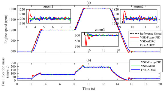
Figure 7.
The control performance comparison of different controllers during the speed tracking mode under standard engine model: (a) The speed response; (b) the control input.

Table 1.
The performance comparison of different criterions for the controllers during the speed tracking mode under standard engine model.
Besides, for the above processes, the intake pressure, exhaust pressure, and turbine rotational speed of the ADRC and Fuzzy-PID controllers are shown in Figure 8. It can be seen that these three variables are smaller in the ADRC during the acceleration processes, which would reduce the pumping power and less the damage of the engine system [2].
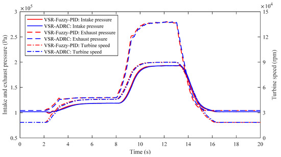
Figure 8.
The intake manifold pressure, exhaust manifold pressure, and turbine speed responses of the variable sampling rate VSR-Fuzzy-Proportional-Integral-Derivative (PID) and VSR-ADRC controllers during the speed tracking mode under standard engine model.
4.3.3. The Attenuating Disturbance Ability
To verify the attenuating disturbance ability of the proposed method, both mutation and wave load disturbances are applied. Figure 9a shows the curve of (all the resistance torque). The load torque is removed at the time of 2 s and added in again at the time of 3 s; then the wave load is introduced at the time of 5 s. Figure 9b shows that during the mutation load disturbances, both the variations of engine speed and settling time are significantly less in the proposed controller. Especially with regard to the settling time, it is around a half of that in the Fuzzy-PID controller. From the zoomed-in graph in Figure 9b, we know that during the wave disturbance, the speed deviation in the proposed controller is obviously smaller. Other performance indexes for the wave disturbance are given in Table 2, which indicates that the proposed controller can keep less fuel consumption and smaller speed fluctuation in the situation of wave disturbance. When the ship voyages in the sea, it encounters a wave or ocean current. Hence, although the fuel consumption in the proposed controller is only 0.52% less than that in the Fuzzy-PID controller and so we can conclude that the proposed method has considerable fuel economy.
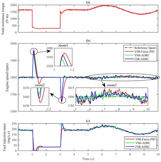
Figure 9.
The control performance comparison of different controllers during the load disturbance conditions under standard engine model: (a) The total resistance torque; (b) the speed responses; (c) the control input.

Table 2.
The performance comparison of different criterions for the controllers with wave load disturbances under standard engine model.
The estimate error of state and the estimate of state for the VSR-ADRC and FSR-ADRC controllers, we demonstrate our findings in Figure 10. From Figure 10a, we know that the state tracking of is more accurate in the VSR-ADRC. As shown in Figure 10b, the VSR-ADRC consumes less time to make the estimate of extended state converge to steady-state. As a result, the VSR-ADRC can estimate and compensate the external disturbance more quickly than the FSR-ADRC. Such characteristics are the reason why the VSR-ADRC outperforms the FSR-ADRC. It is easy to understand that, as the sampling and control in the VSR-ADRC are synchronized with the CA based fuel injection and in-cylinder powering process; hence, the VSR-ADRC can control the engine speed more efficiently and obtain better control performance.
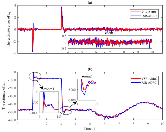
Figure 10.
The estimate performance comparison of Extended State Observers (ESOs) for VSR-ADRC and FSR-ADRC during the load disturbance conditions under standard engine model: (a) The estimate error of ; (b) The estimate of .
4.3.4. The Robustness towards Model Uncertainties
In this study, we primarily consider two kinds of uncertainties: the variations of and . is affected by the effect of incidental water, which results in dynamic changing in engine speed response. As shown in Equation (5), a smaller leads to a faster response of the engine speed, causing larger overshoot during speed tracking process and bigger speed variation under disturbance conditions. It should be noted that the over-speed is pretty harmful for the engine system which should be well considered in a speed controller.
Therefore, in order to test the robustness of the proposed controller towards the mentioned uncertainties, for the proposed controller and the VSR-Fuzzy-PID controller, the speed response curves of the engine system with a 20% decrease in and a 10% increase in under the load disturbance condition mentioned above are plotted in Figure 11. According to Table 2, the corresponding evaluation indexes of Figure 11 are refreshed in Table 3. As shown in Figure 11 and Table 3, the proposed controller still has superiorities in control performance. Especially, as shown in Figure 11a-zoom1, the engine speed in the proposed controller has a margin of 20 rpm before exceeding the maximum engine speed (2000 rpm). On the contrary, the speed in the VSR-Fuzzy-PID controller almost reaches to the maximum speed during the sudden unload process. Hence, we can conclude that the proposed method has better robustness and adaptation towards system uncertainties.
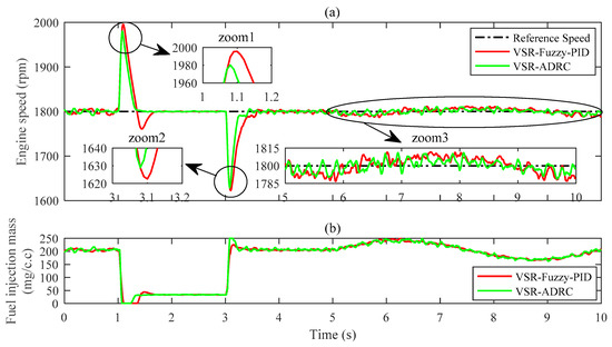
Figure 11.
The control performance comparison between the VSR-Fuzzy-PID and VSR-ADRC controllers during the load disturbance conditions under changed engine model: (a) The speed responses; (b) the control input.

Table 3.
The performance comparison of different criterions for the controllers with wave load disturbances under changed engine model.
5. Discussion
The obtained results demonstrate that, compared with the VSR-Fuzzy-PID, the VSR-ADRC gains better adaptation and robust in engine speed control. Such a concept considers the inherent characteristics in IC engines, i.e., the fuel injection and in-cylinder process are CA or event based. In previous studies, with regard to using ADRC in IC engines speed control, there is not much attention drawn to such traits. However, in the practical control of IC engine speed, it is necessary to design the control strategy in the CA domain and some algorithms can only be implemented in the CA domain, such as the torque balancing control [58,59], which needs to treat the individual cylinder independently in the CA domain. As the proposed ADRC method is CA based, therefore, it can be combined with the torque balancing control strategy to further enhance the speed control performance.
In addition, most the studies focus on investigating the ADRC via engine models under simulation condition [22,23]. Only [8] provides bench experiment, but the structure used therein is the fixed sample interval based ESO. Nevertheless, in this study, the controller is verified on the HIL system and the employed engine model is CA resolved which is different from the previous studies. Moreover, the control algorithm is implemented on a real ECU. Hence, the controller investigated in this study is of significant meanings which provides a bridge for making use of ADRC into practical engine speed control.
In this study, the control parameters for ADRC are designed via considering the variable sampling rate, so that it is more understandable. In Equation (1), the sampling interval is varying with the engine speed and the control bandwidth is also designed to vary with the engine speed, resulting in changing with engine speed as well. In the previous research [24], where a set of fixed parameters are designed for the marine engine speed controller, lead to a compromise control performance for considering the whole operation conditions. It should be noted that the parameters tuning for the proposed scheme is simple. Actually, only two parameters need to be tuned: and . Whereas in the Fuzzy-PID controller, three basic coefficients (), the ranges of , , , the fuzzy logic, the universe of discourses for and , need to be adjusted well, which is a heavy task.
There are still some issues to be considered to further improve the control performance of the VSR-ADRC in a marine engine speed control. As the experimental results show, the variations of rotational inertia and load factor would deteriorate the control effect of the VSR-ADRC; it would be effective to correct the parameter then cancel the influence of such variations. indicates that is associated with , , and . Besides, and contain the information of enigne load (related to ) in a certain degree. In [60], an adaptive ESO is employed to improve the performance for a PMSM motor by identifying the load inertia to modify the parameter in ESO online. Therefore, it is reasonable and practical to improve the control performance by modifying the parameter online. In the authors’ previous study [12], the steady-state gain between system output () and the control input () is identified online to improve the control performance. Such steady-state gain can reflect the engine load; hence, the future work can be focused on improving the control performance of the proposed ADRC with the modification of by identifying the steady-state gain online.
6. Conclusions
The engine speed control for marine engine is of great importance. The strong system uncertainties and sophisticated external disturbances make it a challenge to design a high-performance speed controller. In this paper, for a marine engine, a CA based ADRC controller is structured by using the variable sampling rate control. With the discretization method proposed in [38], the discrete-time ESO is obtained with variable sampling interval which depends on engine speed. The convergence of such discrete-time ESO is analyzed, and the parameters that can guarantee its stability is given. In order to verify the proposed control approach, a modified MVEM is employed in which the inherent speed fluctuation caused by discrete indicated torque generation and the cylinder-by-cylinder variations are considered. Finally, by using such an engine model, the proposed controller is tested on the HIL system. Substantial experimental results demonstrate that, compared with the fixed sampling rate ADRC and variable sampling rate Fuzzy-PID, the proposed VSR-ADRC has better adaptation and robustness towards load disturbances (mutation load and wave load) and system uncertainties (the variations of rotational inertia and load factor).
Author Contributions
Data curation, Y.Y.; Formal analysis, Y.L.; Investigation, Q.A. and C.F.; Methodology, R.W.; Project administration, X.M.; Resources, X.L. and Q.A.; Software, R.W. and Y.Y.; Supervision, X.L.; Validation, Y.L. and C.F.; Writing—original draft, R.W.; Writing—review and editing, X.L., Q.A. and X.M.
Funding
This research received no external funding.
Conflicts of Interest
The authors declare no conflict of interest.
References
- Guo, Y.B.; Li, W.Y.; Yu, S.W.; Han, X.; Yuan, Y.B.; Wang, Z.P.; Ma, X.Z. Diesel engine torsional vibration control coupling with speed control system. Mech. Syst. Signal Process. 2017, 94, 1–13. [Google Scholar] [CrossRef]
- Li, X.; Ahmed, Q.; Rizzoni, G. Nonlinear robust control of marine diesel engine. J. Mar. Eng. Technol. 2017, 16, 1–10. [Google Scholar] [CrossRef]
- Radan, D.; Sørensen, A.J.; Johansen, T.A. Inertial control of marine engines and propellers. IFAC Proc. Vol. 2007, 40, 323–328. [Google Scholar] [CrossRef]
- Lynch, C.; Hagras, H.; Callaghan, V. Using uncertainty bounds in the design of an embedded real-time type-2 neuro-fuzzy speed controller for marine diesel engines. In Proceedings of the IEEE International Conference on Fuzzy Systems, Vancouver, BC, Canada, 16–21 July 2006; pp. 1446–1453. [Google Scholar]
- Yuan, Y.; Zhang, M.; Chen, Y.; Mao, X. Multi-sliding surface control for the speed regulation system of ship diesel engines. Trans. Inst. Meas. Control 2018, 40, 22–34. [Google Scholar] [CrossRef]
- Bondarenko, O.; Kashiwagi, M. Statistical consideration of propeller load fluctuation at racing condition in irregular waves. J. Mar. Sci. Technol. 2011, 16, 402–410. [Google Scholar] [CrossRef]
- Wei, J.; Zhang, A.; Qin, D.; Lim, T.C.; Shu, R.; Lin, X.; Meng, F. A coupling dynamics analysis method for a multistage planetary gear system. Mech. Mach. Theory 2017, 110, 27–49. [Google Scholar] [CrossRef]
- Kang, E.; Hong, S.; Sunwoo, M. Idle speed controller based on active disturbance rejection control in diesel engines. Int. J. Automot. Technol. 2016, 17, 937–945. [Google Scholar] [CrossRef]
- Nielsen, K.V.; Blanke, M.; Eriksson, L.; Vejlgaard-Laursen, M. Marine diesel engine control to meet emission requirements and maintain maneuverability. Control Eng. Pract. 2018, 76, 12–21. [Google Scholar] [CrossRef]
- Xiros, N.I. PID marine engine speed regulation under full load conditions for sensitivity H∞-norm specifications against propeller disturbance. J. Mar. Eng. Technol. 2004, 3, 3–11. [Google Scholar] [CrossRef]
- Papalambrou, G.; Kyrtatos, N.P. robust control of marine diesel engine equipped with power-take-in system. IFAC Proc. Vol. 2006, 39, 591–596. [Google Scholar] [CrossRef]
- Wang, R.Z.; Li, X.M.; Liu, Y.F.; Fu, W.J.; Liu, S.; Ma, X.Z. Multiple model predictive functional control for marine diesel engine. Math. Probl. Eng. 2018. [Google Scholar] [CrossRef]
- Broomhead, T.; Manzie, C.; Hield, P.; Shekhar, R.; Brear, M. Economic model predictive control and applications for diesel generators. IEEE Trans. Control Syst. Technol. 2017, 25, 388–400. [Google Scholar] [CrossRef]
- Sun, Q.; Chen, J. Speed governor design based on fuzzy self-tuning PID method for marine diesel engine. In Proceedings of the 5th International Conference on Advanced Design and Manufacturing Engineering, Shenzhen, China, 19–20 September 2015; Volume 39, pp. 1397–1402. [Google Scholar]
- Farouk, N.; Sheng, L.; Said, L. Speed control system on marine diesel engine based on a self-tuning fuzzy PID controller. Res. J. Appl. Sci. Eng. Technol. 2012, 4, 686–690. [Google Scholar]
- Han, J. From PID to active disturbance rejection control. IEEE Trans. Ind. Electron. 2009, 56, 900–906. [Google Scholar] [CrossRef]
- Li, S.H.; Xia, C.J.; Zhou, X. Disturbance rejection control method for permanent magnet synchronous motor speed-regulation system. Mechatronics 2012, 22, 706–714. [Google Scholar] [CrossRef]
- Chang, X.; Li, Y.; Zhang, W.; Wang, N.; Xue, W. Active disturbance rejection control for a flywheel energy storage system. IEEE Trans. Ind. Electron. 2015, 62, 991–1001. [Google Scholar] [CrossRef]
- Cheng, Y.; Chen, Z.; Sun, M.; Sun, Q. Cascade active disturbance rejection control of a high-purity distillation column with measurement noise. Ind. Eng. Chem. Res. 2018, 57, 4623–4631. [Google Scholar] [CrossRef]
- Xue, W.C.; Bai, W.Y.; Yang, S.; Song, K.; Huang, Y.; Xie, H. ADRC with adaptive extended state observer and its application to air-fuel ratio control in gasoline engines. IEEE Trans. Ind. Electron. 2015, 62, 5847–5857. [Google Scholar] [CrossRef]
- Zheng, Q.; Gao, Z.Q. On practical applications of active disturbance rejection control. In Proceedings of the 29th Chinese Control Conference, Beijing, China, 29–31 July 2010; pp. 6095–6100. [Google Scholar]
- Weigang, P.; Hairong, X.; Yaozhen, H.; Changshun, W.; Guiyong, Y. Nonlinear active disturbance rejection controller research of main engine for ship. In Proceedings of the 2010 8th World Congress on Intelligent Control and Automation, Jinan, China, 7–9 July 2010; pp. 4978–4981. [Google Scholar]
- Hua, H.; Ma, N.; Ma, J.; Zhu, X. Robust intelligent control design for marine diesel engine. J. Shanghai Jiaotong Univ. (Sci.) 2013, 18, 660–666. [Google Scholar] [CrossRef]
- Wang, R.; Li, X.; Zhang, J.; Zhang, J.; Li, W.; Liu, Y.; Fu, W.; Ma, X. Speed control for a marine diesel engine based on the combined linear-nonlinear active disturbance rejection control. Math. Probl. Eng. 2018. [Google Scholar] [CrossRef]
- Yurkovich, S.; Simpson, M. Comparative analysis for idle speed control: A crank-angle domain viewpoint. In Proceedings of the 1997 American Control Conference (Cat. No.97CH36041), Albuquerque, NM, USA, 4–6 June 1997; Volume 271, pp. 278–283. [Google Scholar]
- De Santis, E.; Di Benedetto, M.D.; Pola, G. Digital idle speed control of automotive engines: A safety problem for hybrid systems. Nonlinear Anal. Theorymethods Appl. 2006, 65, 1705–1724. [Google Scholar] [CrossRef]
- Tibola, J.R.; Metzka Lanzanova, T.D.; Santos Martins, M.E.; Gruendling, H.A.; Pinheiro, H. Modeling and speed control design of an ethanol engine for variable speed gensets. Control Eng. Pract. 2015, 35, 54–66. [Google Scholar] [CrossRef]
- Osburn, A.W. Performance Enhancement of Internal Combustion Engines Using Crank Angle Domain Control. Ph.D. Thesis, Purdue University, West Lafayette, IN, USA, 2003. [Google Scholar]
- Miklosovic, R.; Radke, A.; Gao, Z. Discrete implementation and generalization of the extended state observer. In Proceedings of the American Control Conference 2006, Minneapolis, MN, USA, 14–16 June 2006; pp. 2209–2215. [Google Scholar]
- Li, J.; Xia, Y.Q.; Qi, X.H.; Wan, H. On convergence of the discrete-time nonlinear extended state observer. J. Frankl. Inst. Eng. Appl. Math. 2018, 355, 501–519. [Google Scholar] [CrossRef]
- Huang, Y.; Wang, J.; Shi, D.; Shi, L. Performance assessment of discrete-time extended state observers: Theoretical and experimental results. IEEE Trans. Circuits Syst. I Regul. Pap. 2018, 65, 2256–2268. [Google Scholar] [CrossRef]
- Huang, Y.; Wang, J.Z.; Shi, D.W.; Shi, L. Toward event-triggered extended state observer. IEEE Trans. Autom. Control 2018, 63, 1842–1849. [Google Scholar] [CrossRef]
- Miskowicz, M. Send-on-delta concept: An event-based data reporting strategy. Sensors 2006, 6, 49–63. [Google Scholar] [CrossRef]
- Pawlowski, A.; Guzman, J.L.; Rodriguez, F.; Berenguel, M.; Sanchez, J.; Dormido, S. The influence of event-based sampling techniques on data transmission and control performance. In Proceedings of the 14th IEEE International Conference on Emerging Technologies and Factory Automation (ETFA), Mallorca, Spain, 22–25 September 2009. [Google Scholar]
- Khashooei, B.A.; Antunes, D.J.; Heemels, W. Output-based event-triggered control with performance guarantees. IEEE Trans. Autom. Control 2017, 62, 3646–3652. [Google Scholar] [CrossRef]
- Hung, C.-W.; Lin, C.-T.; Liu, C.-W.; Yen, J.-Y. A variable-sampling controller for brushless DC motor dives with low-resolution position sensors. IEEE Trans. Ind. Electron. 2007, 54, 2846–2852. [Google Scholar] [CrossRef]
- Xue, W.C.; Huang, Y. Tuning of sampled-data ADRC for nonlinear uncertain systems. J. Syst. Sci. Complex. 2016, 29, 1187–1211. [Google Scholar] [CrossRef]
- Herbst, G. A simulative study on active disturbance rejection control (ADRC) as a control tool for practitioners. Electronics 2013, 2, 246–279. [Google Scholar] [CrossRef]
- Jimbo, T.; Hayakawa, Y. A physical model for engine control design via role state variables. Control Eng. Pract. 2011, 19, 276–286. [Google Scholar] [CrossRef]
- Jiang, D.; Huang, Y.; Li, G.; Hao, D.; Zuo, Z. Design of a speed tracking controller for heavy-duty vehicles with an all-speed governor based on a model predictive control strategy. Int. J. Engine Res. 2017, 18, 930–940. [Google Scholar] [CrossRef]
- Wahlstrom, J.; Eriksson, L. Modeling of a Diesel Engine with VGT and EGR Including Oxygen Mass Fraction; Linköping University Electronic Press: Linköping, Sweden, 2006. [Google Scholar]
- Wahlstrom, J.; Eriksson, L. Modelling diesel engines with a variable-geometry turbocharger and exhaust gas recirculation by optimization of model parameters for capturing non-linear system dynamics. Proc. Inst. Mech. Eng. Part D J. Automob. Eng. 2011, 225, 960–986. [Google Scholar] [CrossRef]
- Xie, H.; Song, K.; Yang, S.; Tatsumi, J.; Zheng, Q.L.; Zhang, H.; Gao, Z.Q. On decoupling control of the VGT-EGR system in diesel engines: A new framework. IEEE Trans. Control Syst. Technol. 2016, 24, 1788–1796. [Google Scholar] [CrossRef]
- Balluchi, A.; Benvenuti, L.; Benedetto, M.D.D.; Pinello, C.; Sangiovanni-Vincentelli, A.L. Automotive engine control and hybrid systems: Challenges and opportunities. Proc. IEEE 2000, 88, 888–912. [Google Scholar] [CrossRef]
- Schulze, T.; Wiedemeier, M.; Schuette, H. Crank Angle-Based Diesel Engine Modeling for Hardware-in-the-Loop Applications with In-Cylinder Pressure Sensors; SAE Technical Paper 2007-01-1303; SAE International: Warrendale, PA, USA, 2007. [Google Scholar] [CrossRef]
- Ali, S.A.; Saraswati, S. Cycle-by-cycle estimation of IMEP and peak pressure using crankshaft speed measurements. J. Intell. Fuzzy Syst. 2015, 28, 2761–2770. [Google Scholar] [CrossRef]
- Al-Durra, A. A model-dased methodology for real-time estimation of diesel engine cylinder pressure. J. Dyn. Syst. Meas. Control 2011, 133, 031005. [Google Scholar] [CrossRef]
- Casoli, P.; Gambarotta, A.; Pompini, N.; Caiazzo, U.; Lanfranco, E.; Palmisano, A. Development and validation of a “crank-angle” model of an automotive turbocharged engine for HiL aApplications. In Proceedings of the Ati 2013—68th Conference of the Italian Thermal Machines Engineering Association, Bologna, Italy, 11–13 September 2013; Morini, G.L., Bianchi, M., Saccani, C., Cocchi, A., Eds.; Volume 45, pp. 839–848. [Google Scholar]
- Li, R.; Huang, Y.; Li, G.; Song, H. Control-oriented modeling and analysis for turbocharged diesel engine system. In Proceedings of the International Conference on Measurement, Information and Control, Harbin, China, 16–18 August 2013; pp. 855–860. [Google Scholar]
- Wang, H.Y.; Wu, X.Y. Modified mean value model for a common rail marine diesel engine. In Proceedings of the IEEE 2008 International Workshop on Modelling, Simulation and Optimization (WMSO), Hong Kong, China, 27–28 December 2008; pp. 160–162. [Google Scholar]
- Wang, R.; Li, X.; Ahmed, Q.; Liu, Y.; Ma, X. Speed control of a marine engine using predictive functional control based PID controller. In Proceedings of the 2018 Annual American Control Conference (ACC), Milwaukee, WI, USA, 27–29 June 2018; pp. 3908–3914. [Google Scholar]
- Miklosovic, R.; Gao, Z.Q. A robust two-degree-of-freedom control design technique and its practical application. In Proceedings of the 2004 IEEE Industry Applications Conference 2004, Seattle, WA, USA, 3–7 October 2004; Volumes 1–4, pp. 1495–1502. [Google Scholar]
- Song, C.; Wei, C.; Yang, F.; Cui, N. High-order sliding mode-based fixed-time active disturbance rejection control for quadrotor attitude system. Electronics 2018, 7, 357. [Google Scholar] [CrossRef]
- Gao, Z. Scaling and bandwidth-parameterization based controller tuning. In Proceedings of the American Control Conference, Denver, CO, USA, 4–6 June 2003; pp. 4989–4996. [Google Scholar]
- Astrom, K.J.; Hagglund, T. The future of PID control. Control Eng. Pract. 2001, 9, 1163–1175. [Google Scholar] [CrossRef]
- Skogestad, S. Simple analytic rules for model reduction and PID controller tuning. J. Process Control 2003, 13, 291–309. [Google Scholar] [CrossRef]
- Wang, L.; Yang, Y.; Guo, C. CMAC-PID integrated controller used in marine propulsion plant. In Proceedings of the 2010 International Conference on Intelligent Control and Information Processing, Dalian, China, 13–15 August 2010; pp. 367–370. [Google Scholar]
- Li, P.; Shen, T.; Liu, D. Idle speed performance improvement via torque balancing control in ignition-event scale for SI engines with multi-cylinders. Int. J. Engine Res. 2012, 13, 65–76. [Google Scholar] [CrossRef]
- Ostman, F.; Toivonen, H.T. Adaptive cylinder balancing of internal combustion engines. IEEE Trans. Control Syst. Technol. 2011, 19, 782–791. [Google Scholar] [CrossRef]
- Li, S.H.; Liu, Z.G. Adaptive speed control for permanent-magnet synchronous motor system with variations of load inertia. IEEE Trans. Ind. Electron. 2009, 56, 3050–3059. [Google Scholar] [CrossRef]
© 2019 by the authors. Licensee MDPI, Basel, Switzerland. This article is an open access article distributed under the terms and conditions of the Creative Commons Attribution (CC BY) license (http://creativecommons.org/licenses/by/4.0/).